
Cipec Expansion Joints
20
CIPEC Expansion Joints
-
Upload
patrickjman -
Category
Documents
-
view
494 -
download
14
Transcript of Cipec Expansion Joints

CIPECExpansion Joints

expansion jointsCIPEC
CIPEC expansion joints are designed to enable continuoustraffic between two structures, accommodating structuralmovements due to creep, shrinkage effects, temperature
variations and deformations under live load.
They are suitable for all reinforced concrete, prestressedconcrete, composite and steel structures,
and particularly for bridge decks.
CIPEC expansion joints are also designed to allow sufficientvertical movement so that bearings can be replaced without
needing to disassemble the expansion joint.
They enable drainage of runoff water and theyare designed to minimize traffic noise.
Small movement expansion joints
Medium movement expansion joints
Large movement expansion joints
page 3: JEP joints
page 5: WR joints
page 7: WOSd joints
page 9: Wd joints
page 13: WP joints
CO N T E N TSCONTENTS
CIPEC Expansion Joints 1
C I P EC EXPANSION JOINTS
PRODUCT RANGE
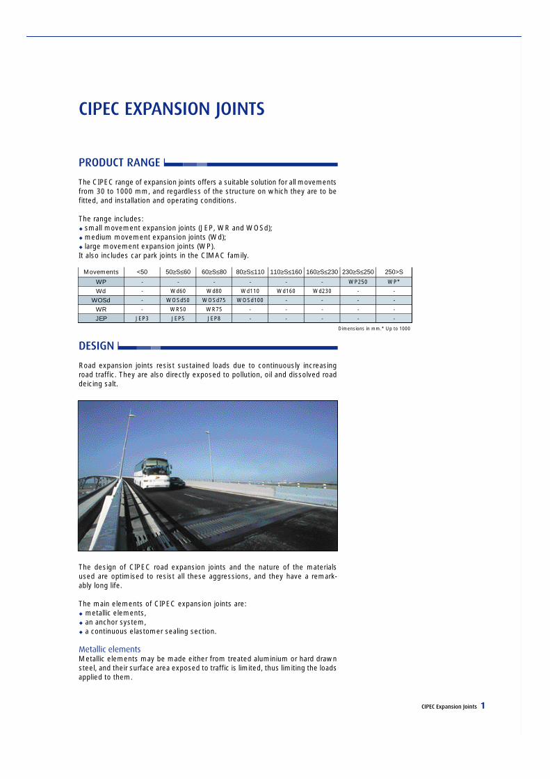
The CIPEC range of expansion joints offers a suitable solution for all movementsfrom 30 to 1000 mm, and regardless of the structure on which they are to befitted, and installation and operating conditions.
The range includes:u small movement expansion joints (JEP, WR and WOSd);u medium movement expansion joints (Wd);u large movement expansion joints (WP).It also includes car park joints in the CIMAC family.
DESIGN
Road expansion joints resist sustained loads due to continuously increasingroad traffic. They are also directly exposed to pollution, oil and dissolved roaddeicing salt.
The design of CIPEC road expansion joints and the nature of the materialsused are optimised to resist all these aggressions, and they have a remark-ably long life.
The main elements of CIPEC expansion joints are:u metallic elements, u an anchor system, u a continuous elastomer sealing section.
Metallic elementsMetallic elements may be made either from treated aluminium or hard drawnsteel, and their surface area exposed to traffic is limited, thus limiting the loadsapplied to them.
Dimensions in mm.* Up to 1000
WPWd
WOSdWRJEP
-
-
-
-
JEP3
Movements <50
-
Wd60
WOSd50
WR50
JEP5
50≥S≤60
-
Wd80
WOSd75
WR75
JEP8
60≥S≤80
-
Wd110
WOSd100
-
-
80≥S≤110
-
Wd160
-
-
-
110≥S≤160
-
Wd230
-
-
-
160≥S≤230
WP250
-
-
-
-
230≥S≤250
WP*
-
-
-
-
250>S

2 CIPEC Expansion Joints
Metallic elements of joints with medium and large movements have triangularor straight teeth that aid the user during installation and mitigate road noise,regardless of the joint opening distance.These teeth may also be installed on skew bridges without introducing anystress on the expansion joints.
Anchor systemsCIPEC road expansion joints use one of the following two systems to anchormetallic elements to the structures to be equipped, depending on the model:u either prestressed attachments, u or a resin mortar bonding to the support (for the JEP) joint.
The elastomer sectionA continuous elastomer section over the entire length of the road surfaceexpansion joint is inserted between metallic elements. It prevents the pene-tration of foreign bodies and provides waterproofing against runoff water.This section is installed underneath the surface layer and does not resist traf-fic loads.
Upstands of the elastomer section at the ends of the joint line also contributeto the leak tightness of the joint. A drain installed on the upstream side of thejoint line also helps by collecting any water that infiltrates through the road sur-face layer.
QUALITY OF CIPEC EXPANSION JOINTS
A badly designed expansion joint, or simply a wrong choice of an expansionjoint, can cause severe and irreversible disorders for itself and for the struc-tures on which it is installed.
CIPEC joints are designed for quality, and are very much appreciated for thebenefits that they provide as has been demonstrated on many structural pro-jects for more than 30 years:u excellent traffic comfort;u long life;u low noise;u high resistance to corrosion;u no horizontal reaction. Ve rtical movements of stru c t u res are possible (for jack-
ing, etc.) without the need to disassemble the joint;u protection of surfaces under the joint;u good resistance to heavy duty and frequent traffic loads;u adaptability to all surface structure types;u easy installation on new or old structures;u low servicing and maintenance.
CIPEC Expansion Joints / Small Movements 3
JEP EXPANSION JOINTS
DESIGN
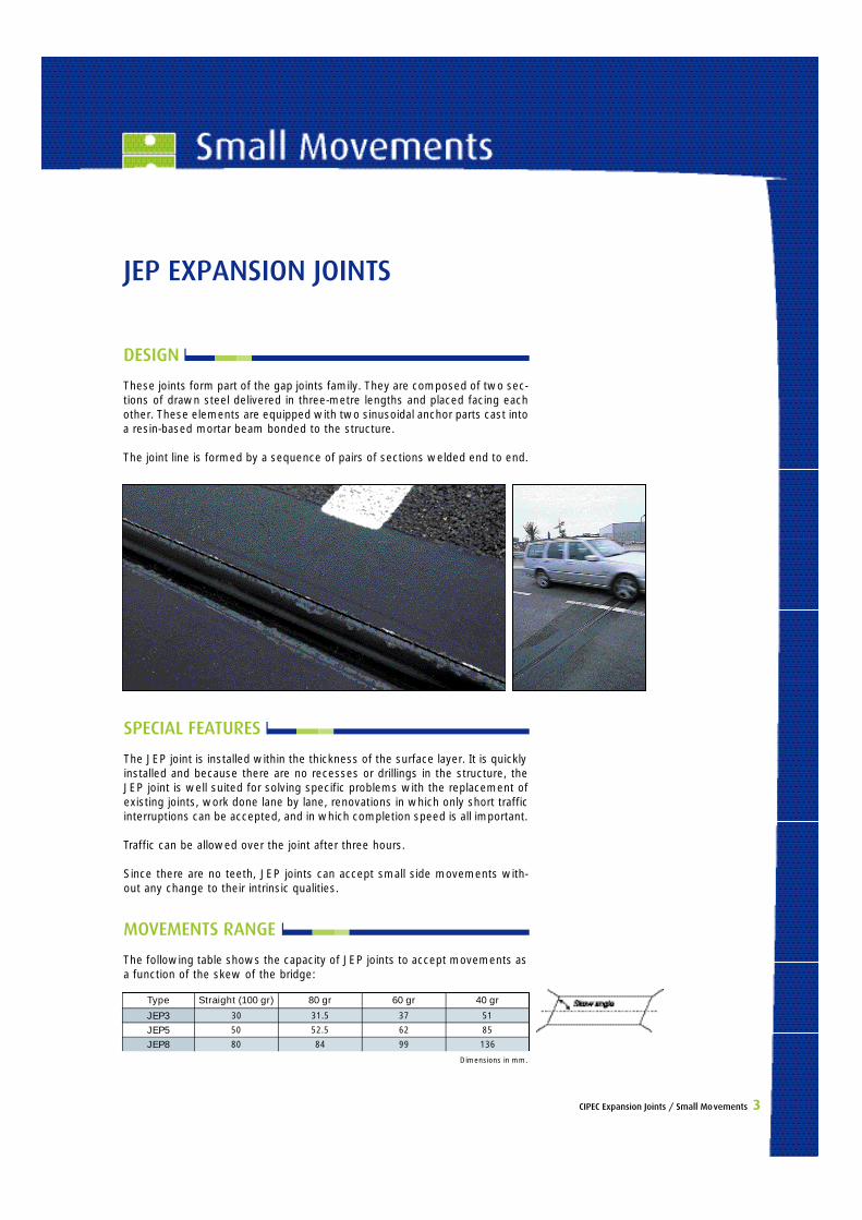
These joints form part of the gap joints family. They are composed of two sec-tions of drawn steel delivered in three-metre lengths and placed facing eachother. These elements are equipped with two sinusoidal anchor parts cast intoa resin-based mortar beam bonded to the structure.
The joint line is formed by a sequence of pairs of sections welded end to end.
SPECIAL FEATURES
The JEP joint is installed within the thickness of the surface layer. It is quicklyinstalled and because there are no recesses or drillings in the structure, theJEP joint is well suited for solving specific problems with the replacement ofexisting joints, work done lane by lane, renovations in which only short trafficinterruptions can be accepted, and in which completion speed is all important.
Traffic can be allowed over the joint after three hours.
Since there are no teeth, JEP joints can accept small side movements with-out any change to their intrinsic qualities.
Dimensions in mm.
JEP3JEP5JEP8
30
50
80
Type Straight (100 gr)
31.5
52.5
84
80 gr
37
62
99
60 gr
51
85
136
40 gr
MOVEMENTS RANGE
The following table shows the capacity of JEP joints to accept movements asa function of the skew of the bridge:
4 CIPEC Expansion Joints / Small Movements
ACCESSORIES
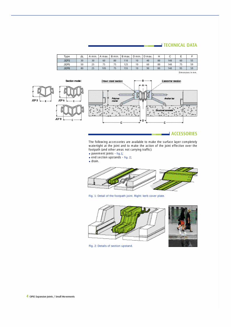
The following accessories are available to make the surface layer completelywatertight at the joint and to make the action of the joint effective over thefootpath (and other areas not carrying traffic): u pavement joints - fig.1;u end section upstands - fig. 2;u drain.
Fig. 1: Detail of the footpath joint. Right: kerb cover plate.
Fig. 2: Details of section upstand.
Dimensions in mm.
JEP3JEP5JEP8
30
50
80
Type ∆L
30
25
25
A min.
60
75
105
A max.
80
75
75
B min.
110
125
155
B max.
10
10
10
D min.
40
60
90
D max.
80
80
80
H
140
140
140
C
60
75
95
E
55
59
59
F
TECHNICAL DATA
CIPEC Expansion Joints / Small Movements 5
WR EXPANSION JOINTS
DESIGN
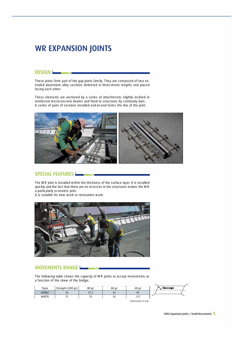
These joints form part of the gap joints family. They are composed of two ex-truded aluminium alloy sections delivered in three-metre lengths and placedfacing each other.
These elements are anchored by a series of attachments slightly inclined inreinforced microconcrete beams and fixed to structures by continuity bars.A series of pairs of sections installed end-to-end forms the line of the joint.
SPECIAL FEATURES
The WR joint is installed within the thickness of the surface layer. It is installedquickly and the fact that there are no recesses in the structures makes the WRa particularly economic joint.It is suitable for new work or renovation work.
Dimensions in mm.
WR50WR75
50
75
Type Straight (100 gr)
52.5
79
80 gr
62
92
60 gr
85
127
40 gr
MOVEMENTS RANGE
The following table shows the capacity of WR joints to accept movements asa function of the skew of the bridge:
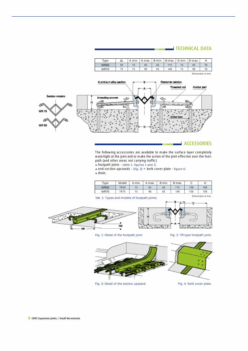
Tab. 1: Types and models of footpath joints.
6 CIPEC Expansion Joints / Small Movements
TECHNICAL DATA
ACCESSORIES
The following accessories are available to make the surface layer completelyw a t e rtight at the joint and to make the action of the joint effective over the foot-path (and other areas not carrying traffic):u footpath joints - table 1, figures 1 and 2;u end section upstands - (fig. 3) + kerb cover plate - figure 4;u drain.
Dimensions in mm.
WR50WR75
50
75
Type ∆L
15
15
A min.
65
90
A max.
65
65
B min.
115
140
B max.
15
15
D min.
65
90
D max.
70
70
H
Dimensions in mm.
WR50WR75
TR50
TR75
Type M o d e l
15
15
A min.
65
90
A max.
65
65
B min.
115
140
B max.
150
150
C
100
100
H
Fig. 1: Detail of the footpath joint. Fig. 2: TR type footpath joint.
Fig. 3: Detail of the section upstand. Fig. 4: Kerb cover plate.
CIPEC Expansion Joints / Small Movements 7
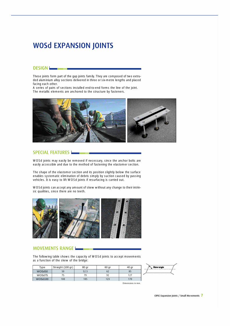
WOSd EXPANSION JOINTS
DESIGN
These joints form part of the gap joints family. They are composed of two extru -ded aluminium alloy sections delivered in three or six-metre lengths and placedfacing each other.A series of pairs of sections installed end-to-end forms the line of the joint.The metallic elements are anchored to the structure by fasteners.
SPECIAL FEATURES
WOSd joints may easily be removed if necessary, since the anchor bolts areeasily accessible and due to the method of fastening the elastomer section.
The shape of the elastomer section and its position slightly below the surfaceenables systematic elimination of debris simply by suction caused by passingvehicles. It is easy to lift WOSd joints if resurfacing is carried out.
WOSd joints can accept any amount of skew without any change to their intrin-s i c qualities, since there are no teeth.
Dimensions in mm.
WOSd50WOSd75
WOSd100
50
75
100
Type Straight (100 gr)
52.5
79
105
80 gr
62
92
123
60 gr
85
127
170
40 gr
MOVEMENTS RANGE
The following table shows the capacity of WOSd joints to accept movementsas a function of the skew of the bridge:
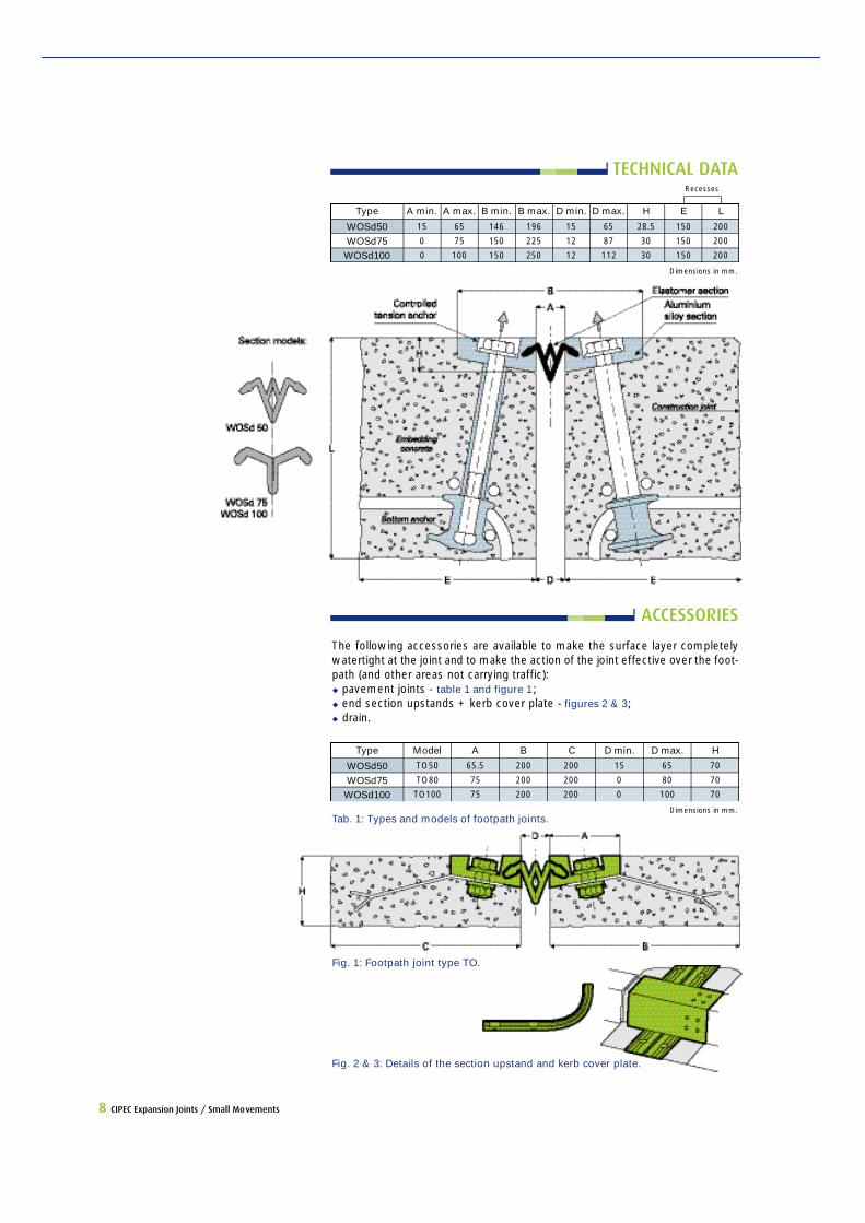
Tab. 1: Types and models of footpath joints.Dimensions in mm.
WOSd50WOSd75
WOSd100
TO50
TO80
TO100
Type M o d e l
65.5
75
75
A
200
200
200
B
200
200
200
C
15
0
0
D min.
65
80
100
D max.
70
70
70
H
ACCESSORIES
The following accessories are available to make the surface layer completelyw a t e rtight at the joint and to make the action of the joint effective over the foot-path (and other areas not carrying traffic): u pavement joints - table 1 and figure 1 ;u end section upstands + kerb cover plate - figures 2 & 3;u drain.
8 CIPEC Expansion Joints / Small Movements
Dimensions in mm.
WOSd50WOSd75
WOSd100
15
0
0
Type A min.
65
75
100
A max.
146
150
150
B min.
196
225
250
B max.
15
12
12
D min.
65
87
112
D max.
28.5
30
30
H
150
150
150
E
200
200
200
L
Recesses
TECHNICAL DATA
Fig. 1: Footpath joint type TO.
Fig. 2 & 3: Details of the section upstand and kerb cover plate.
CIPEC Expansion Joints / Medium Movements 9
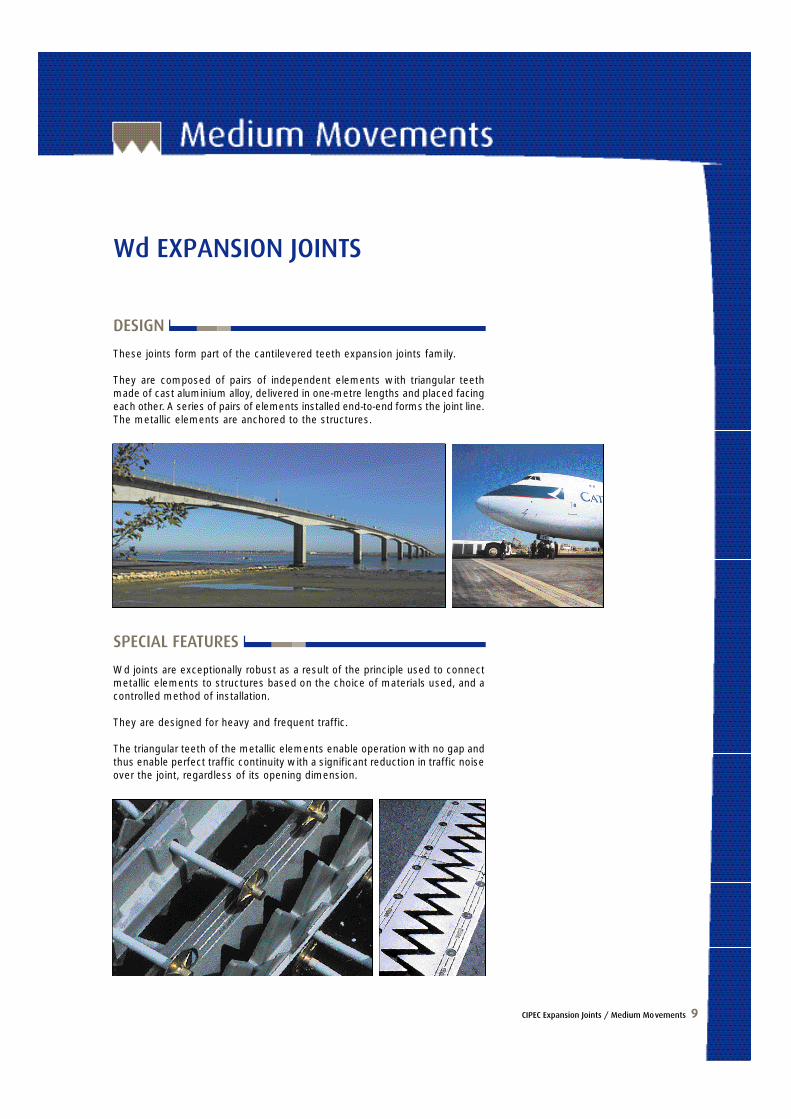
Wd EXPANSION JOINTS
DESIGN
These joints form part of the cantilevered teeth expansion joints family.
They are composed of pairs of independent elements with triangular teethmade of cast aluminium alloy, delivered in one-metre lengths and placed facingeach other. A series of pairs of elements installed end-to-end forms the joint line.The metallic elements are anchored to the structures.
SPECIAL FEATURES
Wd joints are exceptionally robust as a result of the principle used to connectmetallic elements to stru c t u res based on the choice of materials used, and acontrolled method of installation.
They are designed for heavy and frequent traffic.
The triangular teeth of the metallic elements enable operation with no gap andthus enable perfect traffic continuity with a significant reduction in traffic noiseover the joint, regardless of its opening dimension.
10 CIPEC Expansion Joints / Medium Movements
MOVEMENTS RANGE
The following table shows the capacity of Wd joints to accept movements asa function of the skew of the bridge:
Dimensions in mm.
Wd60Wd80Wd110Wd160Wd230
60
80
110
160
230
Type Straight (100 gr)
61
84
116
169
185
80 gr
71
92
104
158
127
60 gr
66
85
92
141
102
40 gr
67
86
90
139
97
30 gr
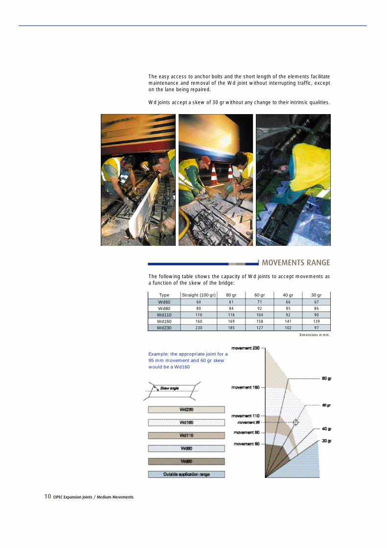
The easy access to anchor bolts and the short length of the elements facilitatemaintenance and removal of the Wd joint without interrupting traffic, excepton the lane being repaired.
Wd joints accept a skew of 30 gr without any change to their intrinsic qualities.
Example: the appropriate joint for a95 mm movement and 60 gr skewwould be a Wd160
CIPEC Expansion Joints / Medium Movements 11
Dimensions in mm.
Wd60Wd80Wd110Wd160Wd230
TO80
TO80
PL110
PL160
PL230
Type M o d e l
75
75
200
260
350
A
200
200
100
100
100
B
200
200
200
250
320
C
5
5
40
50
70
D min.
65
85
150
210
300
D max.
70
70
120
120
120
H
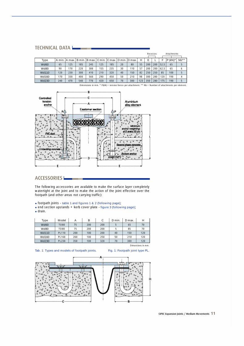
ACCESSORIES
The following accessories are available to make the surface layer completelywatertight at the joint and to make the action of the joint effective over thefootpath (and other areas not carrying traffic):
u footpath joints - table 1 and figures 1 & 2 (following page);u end section upstands + kerb cover plate - figure 3 (following page);u drain.
Recesses Attachments
Dimensions in mm. * P(kN) = tension forces per attachment. ** Nb = Number of attachments per element.
Wd60Wd80Wd110Wd160Wd230
65
90
120
170
240
Type A min.
125
170
230
330
470
A max.
185
220
300
400
540
B min.
245
300
410
560
770
B max.
125
155
210
290
420
C min.
185
235
320
450
650
C max.
20
30
40
50
70
80
110
150
210
300
D min. D max.
55
57
82
98
123
H
200
200
250
300
350
E
200
200
250
280
280
L
52.5
62.5
85
120
175
F
65
65
100
190
190
P (kN)*
5
6
5
4
5
Nb**
TECHNICAL DATA
Tab. 1: Types and models of footpath joints. Fig. 1: Footpath joint type PL.
12 CIPEC Expansion Joints / Medium Movements
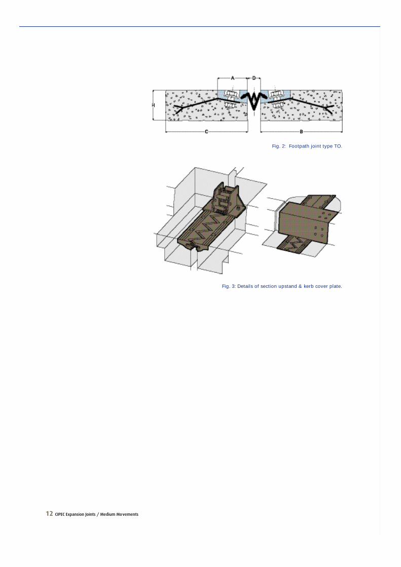
Fig. 3: Details of section upstand & kerb cover plate.
Fig. 2: Footpath joint type TO.
CIPEC Expansion Joints / Large Movements 13
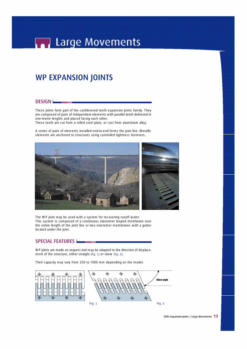
WP EXPANSION JOINTS
DESIGN
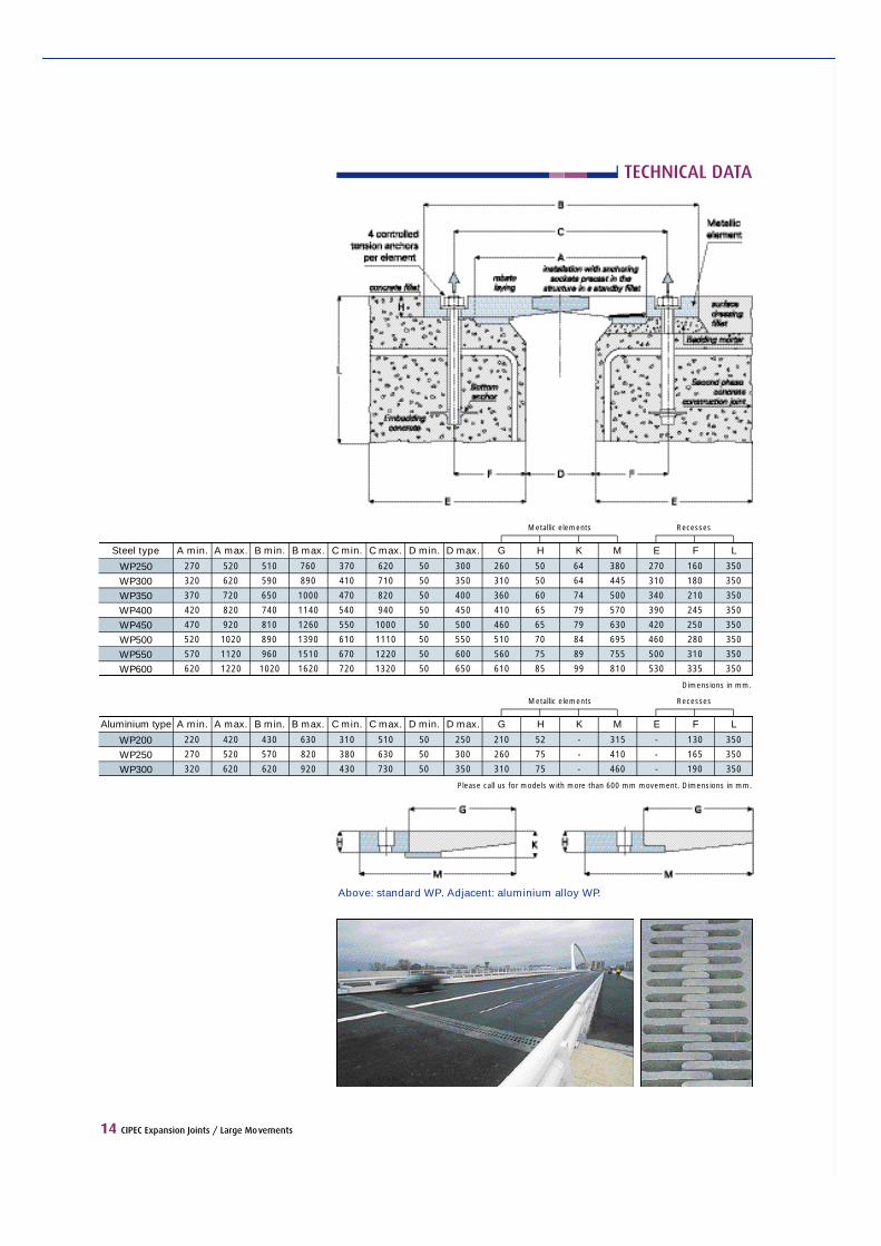
These joints form part of the cantilevered teeth expansion joints family. Theya re composed of pairs of independent elements with parallel teeth delivered inone-metre lengths and placed facing each other.These teeth are cut from a rolled steel plate, or cast from aluminium alloy.
A series of pairs of elements installed end-to-end forms the joint line. Metallicelements are anchored to structures using controlled tightness fasteners.
The WP joint may be used with a system for recovering runoff water.This system is composed of a continuous elastomer looped membrane overthe entire length of the joint line or two elastomer membranes with a gutterlocated under the joint.
SPECIAL FEATURES
WP joints are made on request and may be adapted to the direction of displace-ment of the stru c t u re, either straight (fig. 1) or skew (fig. 2).
Their capacity may vary from 250 to 1000 mm depending on the model.
Fig. 1 Fig. 2
14 CIPEC Expansion Joints / Large Movements
RecessesMetallic elements
Dimensions in mm.
WP250WP300WP350WP400WP450WP500WP550WP600
270
320
370
420
470
520
570
620
Steel type A min.
520
620
720
820
920
1020
1120
1220
A max.
510
590
650
740
810
890
960
1020
B min.
760
890
1000
1140
1260
1390
1510
1620
B max.
370
410
470
540
550
610
670
720
C min.
620
710
820
940
1000
1110
1220
1320
C max.
50
50
50
50
50
50
50
50
D min.
300
350
400
450
500
550
600
650
D max.
260
310
360
410
460
510
560
610
G
50
50
60
65
65
70
75
85
H
64
64
74
79
79
84
89
99
K
380
445
500
570
630
695
755
810
M
270
310
340
390
420
460
500
530
E
160
180
210
245
250
280
310
335
F
350
350
350
350
350
350
350
350
L
Please call us for models with more than 600 mm movement. Dimensions in mm.
RecessesMetallic elements
WP200WP250WP300
220
270
320
Aluminium type A min.
420
520
620
A max.
430
570
620
B min.
630
820
920
B max.
310
380
430
C min.
510
630
730
C max.
50
50
50
D min.
250
300
350
D max.
210
260
310
G
52
75
75
H
-
-
-
K
315
410
460
M
-
-
-
E
130
165
190
F
350
350
350
L
TECHNICAL DATA
Above: standard WP. Adjacent: aluminium alloy WP.
CIPEC Expansion Joints / Large Movements 15
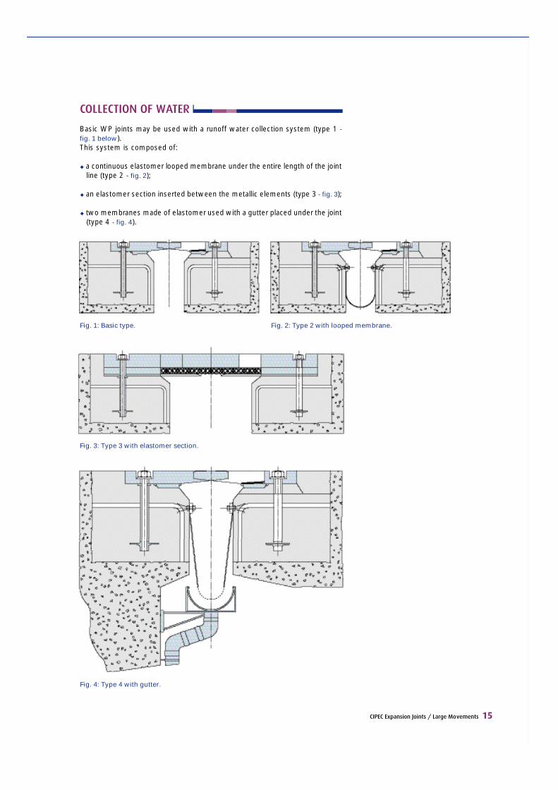
COLLECTION OF WATER
Basic WP joints may be used with a runoff water collection system (type 1 -fig. 1 below).This system is composed of:
u a continuous elastomer looped membrane under the entire length of the jointline (type 2 - fig. 2);
u an elastomer section inserted between the metallic elements (type 3 - fig. 3) ;
u two membranes made of elastomer used with a gutter placed under the joint(type 4 - fig. 4).
Fig. 1: Basic type. Fig. 2: Type 2 with looped membrane.
Fig. 3: Type 3 with elastomer section.
Fig. 4: Type 4 with gutter.
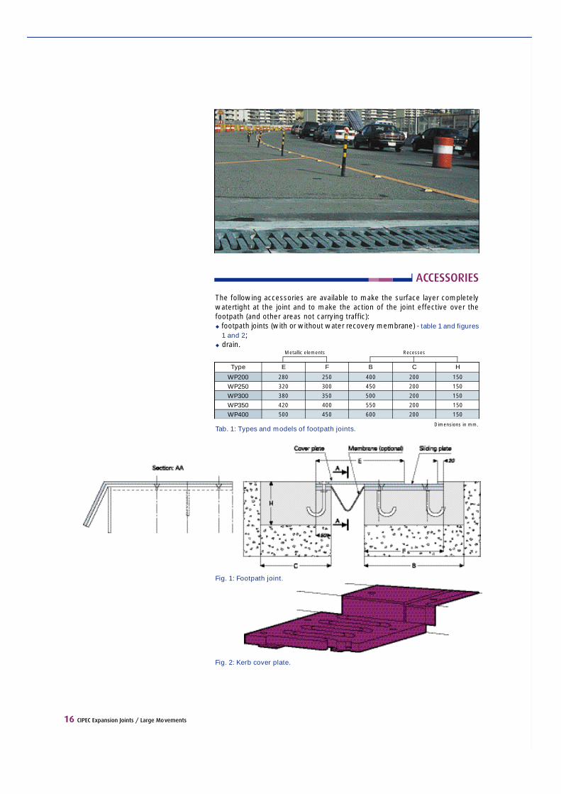
ACCESSORIES
The following accessories are available to make the surface layer completelywatertight at the joint and to make the action of the joint effective over thefootpath (and other areas not carrying traffic):u footpath joints (with or without water re c o v e ry membrane) - table 1 and figure s
1 and 2;u drain.
Recesses
16 CIPEC Expansion Joints / Large Movements
Tab. 1: Types and models of footpath joints.
Fig. 2: Kerb cover plate.
Fig. 1: Footpath joint.
Dimensions in mm.
WP200WP250WP300WP350WP400
280
320
380
420
500
Type E
250
300
350
400
450
F
400
450
500
550
600
B
200
200
200
200
200
C
150
150
150
150
150
H
Metallic elements


1 bis, rue du Petit-Clamar tB.P. 135 - 78148 Vélizy Cedex - France
Tel.: +33 (1) 46 01 84 84Fax: +33 (1) 46 01 85 85
www.freyssinet.com