Cine Film Frame Extractor (Version 5.7) - wkurz.comwkurz.com/download/CineToVid_en.pdf · Cine Film...
23
Cine Film Frame Extractor (Version 5.7) Content: Introduction Prerequisites Installation and Invocation of CineToVid General Remarks The Cine Film Frame Extractor Main Window Initial Setup Functions Generate a New Project Modify a Project The "Define Commands" Dialog Open an Exisiting Project Update the INI File of an Open Project Scan Movie Strips The Options Menu Invocation of ScanController to start a transportation device and a twain driver Extract Frames from Scanned Strips The "Describe Extraction Parameters" Dialog The "Adjust Extraction Parameters" Dialog Set Physical Film Measurements Generate Movie and Resize Images Generate Transitions The Special Transition "Reverse" Delete a Sequence of Strips or Frames Show Movie Integrated Tools The Image Extractor Tool Introduction: The Cine Film Frame Extractor (CineToVid) allows to extract the frames of a cine film movie in order to generate a video file ( ".MOV" or ".AVI". AVI is a Windows container for related audio and video streams), that can be shown on a Personal Computer with a MultiMedia Player. After the required post processing (conversion to the MPEG 2 or MPEG 4 (e.g. DivX format), the film can also be shown via a standard DVD player on a TV-set. To create the video file you can use the CineToVid native "Movie Generator" (it generates .MOV files in the QuickTime MotionJPEG-A format) but you can also use external programs (which normally generate .AVI files). To play the generated movie external programs (MultiMedia Players) are needed. To play MOV files you need Apple QuickTime (or media players that can handle the .MOV format via plugins -e.g. IrfanView), for AVI files the normal Media Players can be used. An extremely universal media player is the VLC Mediaplayer VideoLAN that can handle .MOV as well as .AVI files (see: http://www.videolan.org/ ). [English / international] ). CineToVid functions as a contol center to coordinate the exploitation of these external programs. The video file generation from cine films is a process, that needs a lot of disk space on the computer, therefore only JPEG compressed files are supported. The usage of Bitmap files would raise the amount of needed disk space at least by the factor of 10. This HELP file explains in detail the process to extract the frames and to generate the video file. Prerequisites CineToVid is a Java Application. To run the product you need a SUN Java Virtual Machine (also called a Java Runtime Environment - JRE Version 1.6 or better) and the SUN Java Media Framework JMF (Version 2.1.1e or better) installed on your computer. You can download the SUN JRE for free from "http://www.java.com/en/download/index.jsp" and the SUN JMF you find (also for free) under "http://java.sun.com/products/java - media/jmf/2.1.1/download.html" . You have to register with SUN in order to download the JMF. Do not use the Microsoft VM. It does not support the required functions. If you want during video file creation also generate transitions, I recommend to use "SSMM (Slide Show Movie Maker)" Version 3.7 or better from Joern Thiemann. This program can be downloaded from URL "http://www.joern - thiemann.de" . SSMM can generate a big variety of different transitions. The CineToVid native movie generator can only (if requested) generate slow motion effects to smooth a clip. Transitions are not supported. To Seite 1 von 23 Cine Film Frame Extractor 07.01.2011 file://C:\Program Files\CineToVid\Help\CineToVid_en.htm
Transcript of Cine Film Frame Extractor (Version 5.7) - wkurz.comwkurz.com/download/CineToVid_en.pdf · Cine Film...

Cine Film Frame Extractor (Version 5.7)
Content:
� Introduction � Prerequisites
� Installation and Invocation of CineToVid � General Remarks � The Cine Film Frame Extractor Main Window � Initial Setup � Functions
� Generate a New Project � Modify a Project � The "Define Commands" Dialog � Open an Exisiting Project � Update the INI File of an Open Project � Scan Movie Strips
� The Options Menu � Invocation of ScanController to start a transportation device and a twain driver
� Extract Frames from Scanned Strips � The "Describe Extraction Parameters" Dialog � The "Adjust Extraction Parameters" Dialog
� Set Physical Film Measurements � Generate Movie and Resize Images
� Generate Transitions � The Special Transition "Reverse"
� Delete a Sequence of Strips or Frames � Show Movie
� Integrated Tools � The Image Extractor Tool
Introduction:
The Cine Film Frame Extractor (CineToVid) allows to extract the frames of a cine film movie in order to generate a video file ( ".MOV" or ".AVI". AVI is a Windows container for related audio and video streams), that can be shown on a Personal Computer with a MultiMedia Player. After the required post processing (conversion to the MPEG 2 or MPEG 4 (e.g. DivX format), the film can also be shown via a standard DVD player on a TV-set. To create the video file you can use the CineToVid native "Movie Generator" (it generates .MOV files in the QuickTime MotionJPEG-A format) but you can also use external programs (which normally generate .AVI files). To play the generated movie external programs (MultiMedia Players) are needed. To play MOV files you need Apple QuickTime (or media players that can handle the .MOV format via plugins -e.g. IrfanView), for AVI files the normal Media Players can be used. An extremely universal media player is the VLC Mediaplayer VideoLAN that can handle .MOV as well as .AVI files (see: http://www.videolan.org/). [English / international] ). CineToVid functions as a contol center to coordinate the exploitation of these external programs.
The video file generation from cine films is a process, that needs a lot of disk space on the computer, therefore only JPEG compressed files are supported. The usage of Bitmap files would raise the amount of needed disk space at least by the factor of 10.
This HELP file explains in detail the process to extract the frames and to generate the video file.
Prerequisites
CineToVid is a Java Application. To run the product you need a SUN Java Virtual Machine (also called a Java Runtime Environment - JRE Version 1.6 or better) and the SUN Java Media Framework JMF (Version 2.1.1e or better) installed on your computer. You can download the SUN JRE for free from "http://www.java.com/en/download/index.jsp" and the SUN JMF you find (also for free) under "http://java.sun.com/products/java-media/jmf/2.1.1/download.html" . You have to register with SUN in order to download the JMF. Do not use the Microsoft VM. It does not support the required functions.
If you want during video file creation also generate transitions, I recommend to use "SSMM (Slide Show Movie Maker)" Version 3.7 or better from Joern Thiemann. This program can be downloaded from URL "http://www.joern -thiemann.de" . SSMM can generate a big variety of different transitions. The CineToVid native movie generator can only (if requested) generate slow motion effects to smooth a clip. Transitions are not supported. To
Seite 1 von 23Cine Film Frame Extractor
07.01.2011file://C:\Program Files\CineToVid\Help\CineToVid_en.htm

generate these transitions video editing programs like Adobe Premiere Elements, Pinnacle Studio, or Magix Movie Edit Pro (also known as Magix Video deLuxe) must be used. Other programs that can be used to generate the video file are "VirtualDub" (since Version 1.6.5 - Windows Plattform) and "AVIDemux" (2.0.36 or better - Windows and Linux Platform). Both programms require joint consecutive numbered images in the image folder (see "General Remarks" below). Also the program PhotoToFilm (since build 2.5.0.56 or better) from "KCSoftwares" can be used for video file generation. The most recent version of this program is (as of July 2009) 2.10.0.72.
To additionally compress very large films and to watch such movies I recommend to use (in the Windows environment) the "DivX Codec" (version 5.2.1.or better) and "DivX Player" (version 2.6 or better) . This program can be downloaded from URL "http://www.DivX.com." . Actual version as of September 2008 is 6.8. For films without additional compression (MPEG 2 films) as suitable media players you also can use "WinAmp", "RealPlayer", or the "MS Windows MediaPlayer". In the Linux environment "XViD as Codec" and "MPlayer as Multimedia Player " are recommended. Since December 2005 the DivX Codec (Version 6.1.1) is again available in the Linux environment "http://labs.divx.com/DivXLinuxCodec" .
To generate videos from your cine films you need besides the software that runs on your PC a specific flatbed scanner, that allows you to scan the film with a resolution of at least 3200 dpi (dots per inch) and which has a relatively wide TPU (Transparency Unit). The wider the TPU the better. Annotation: The width of the TPU is important, because the film has to be placed into the scanner along its small side. If the film would be placed into the scanner along it's long side, parts of the scanners calibration area would be covered. This would cause erronous exposion and false colors in the scanned strip. In addition you need to handcraft a film holder and a tool to advance the film in discrete portions. Only this allows convenient film scanning. Industrially manufactured film holders and film advance tools are not available. Manufacturing guides for film guides and transportation devices you can find in the "CineToVid Wiki"
To do the scanning I use an Epson Perfection 4990 PHOTO scanner. This scanner allows to scan the film as a sequence of strips each about 195 mm in length (that is about 42 frames). The desirable resolution is 3200 dpi (or even better 3600 dpi which allows 768x576 dpi frames, the frame size for the PAL video standard) . Although many scanners have an optical resolution of 4800 dpi and more, it is not recommended to go higher than 4000 dpi. A resolution of 4000 dpi or more you should only use if you want to generate 720P images for HDTV TV sets (see: Scan Movie Strips -> Options Menu. Higher resolutions than 3600 dpi do not neccessarily improve the video quality but consume a lot of additional resources (processing time and space on your disk).
Other suitable scanners are the Epson Perfection 4870 PHOTO (which I used until the Espon 4990 became available, and which is shown in the pictures of this document), the Epson V700 and the V750 PRO, and the Canon 9950F. The Canon 9950F I could not test on my own, but it at least from the offered resolution and the width of the transparency unit meets the requirements. In addition the FARE dust removal, Canon offers, seems to be much faster than ICE from Epson. ICE is not really usable, because it increases the scaning time too much and ICE is not recommended for Kodachrome films, and Super 8 films are to more than 90% Kodachrome films.
Setup to scan using manual film transport (with Epson 4870)
Device for manual film transport
Seite 2 von 23Cine Film Frame Extractor
07.01.2011file://C:\Program Files\CineToVid\Help\CineToVid_en.htm
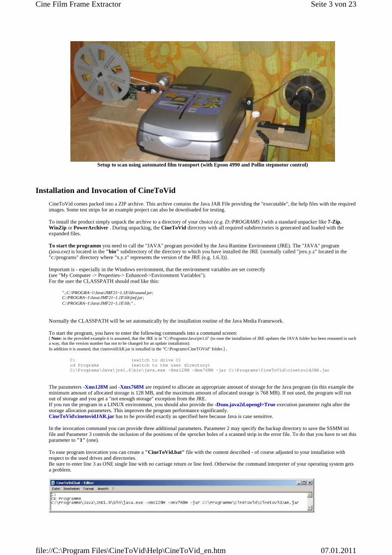
Setup to scan using automated film transport (with Epson 4990 and Pollin stepmotor control)
Installation and Invocation of CineToVid
CineToVid comes packed into a ZIP archive. This archive contains the Java JAR File providing the "executable", the help files with the required images. Some test strips for an example project can also be downloaded for testing.
To install the product simply unpack the archive to a directory of your choice (e.g. D:/PROGRAMS ) with a standard unpacker like 7-Zip, WinZip or PowerArchiver . During unpacking, the CineToVid directory with all required subdirectories is generated and loaded with the expanded files.
To start the programm you need to call the "JAVA" program provided by the Java Runtime Environment (JRE). The "JAVA" program (java.exe) is located in the "bin" subdirectory of the directory to which you have installed the JRE {normally called "jrex.y.z" located in the "c:/programs" directory where "x.y.z" represents the version of the JRE (e.g. 1.6.3)}.
Important is - especially in the Windows environment, that the environment variables are set correctly (see "My Computer -> Properties-> Enhanced->Environment Variables"). For the user the CLASSPATH should read like this:
".;C:\PROGRA~1\Java\JMF21~1.1E\lib\sound.jar; C:\PROGRA~1\Java\JMF21~1.1E\lib\jmf.jar; C:\PROGRA~1\Java\JMF21~1.1E\lib;" .
Normally the CLASSPATH will be set automatically by the installation routine of the Java Media Framework.
To start the program, you have to enter the following commands into a command screen: [ Note: in the provided example it is assumed, that the JRE is in "C:\Programs\Java\jre1.6" (to ease the installation of JRE updates the JAVA folder has been renamed in such a way, that the version number has not to be changed for an update installation). In addition it is asumed, that cinetovidJAR.jar is installed in the "C:\Programs\CineTOVid" folder.] .
C: (switch to drive C) cd Programs (switch to the user directory) C:\Programs\Java\jre1.6\bin\java.exe -Xms128M -Xmx768M -jar C:\Programs\CineToVid\cinetovidJAR.jar
The parameters -Xms128M and -Xmx768M are required to allocate an appropriate amount of storage for the Java program (in this example the minimum amount of allocated storage is 128 MB, and the maximum amount of allocated storage is 768 MB). If not used, the program will run out of storage and you get a "not enough storage" exception from the JRE. If you run the program in a LINUX environment, you should also provide the -Dsun.java2d.opengl=True execution parameter right after the storage allocation parameters. This improves the program performance significantly. CineToVid\cinetovidJAR.jar has to be provided exactly as specified here because Java is case sensitive.
In the invocation command you can provide three additional parameters. Parameter 2 may specify the backup directory to save the SSMM ini file and Parameter 3 controls the inclusion of the positions of the sprocket holes of a scanned strip in the error file. To do that you have to set this parameter to "1" (one).
To ease program invocation you can create a "CineToVid.bat" file with the content described - of course adjusted to your installation with respect to the used drives and directories. Be sure to enter line 3 as ONE single line with no carriage return or line feed. Otherwise the command interpreter of your operating system gets a problem.
Seite 3 von 23Cine Film Frame Extractor
07.01.2011file://C:\Program Files\CineToVid\Help\CineToVid_en.htm
Example of a .BAT file - taken from a German Windows installation
General Remarks:
To minimize disk storage requirements the strips must be stored in the strip directory as JPEG files. The extracted frames are also stored as JPG files.
File names for strips [XXXXGSSS.jpg] are composed from a 4 byte base (project) name [XXXX] ,a 1 digit strip group [G] and a 3 digit strip sequence number [SSS and the .jpg file extension. ( Example: DFLT1001.jpg )
File names for frames are composed from a 4 byte base (project) name , a 4 digit strip sequence number, a 2 digit frame sequence number, and the .jpg file extension. ( Example: DFLT100101.jpg )
If option "Use joint numbering scheme" is set via the "Options" menu, than the image sequence is numbered jointly (without gaps). The image sequence number is calculated from the strip number and the position of the frame within the strip. This allows the usage of programs like AVIDemux and VirtualDub to generate the video file. ( Example "disjoint numbering": XXXX100101.jpg, XXXX100102.jpg, ......XXXX100143.jpg, XXXX100201.jpg, XXXX100202.jpg........XXXX100243.jpg..... Example "joint numbering": XXXX100101.jpg, XXXX100102.jpg, ............ XXXX100199.jpg, XXXX100200.jpg, XXXX100201.jpg, ........ XXXX100299.jpg.)
Take care, when renaming "strips" and "frames" files. The first 4 characters of the file name must start with the base file name (that is the project name). If this is not the case, CineToVid generates an error message.
File names for movies (MOV or AVI file) are composed from the 4 byte project name appended by a file name suffix (any valid length) and the file extension ".avi". ( Example XXXX1A.mov )
The whole movie generation process is composed from the following steps:
1. Scan your movie with the flatbed scanner. The result are strips of a discrete length stored in the strip directory. Note and Warning: This is the really time consuming task and probably a very boring one. The remaining tasks are almost fully automated. To do the scanning you need a lot of patience. If you are very experienced and you have built yourself a real good movie transportation tool, you can do dependent on the used computer (relevant parameters are processor speed and disk speed) and the used scanner about 30 to 60 strips (990 to 2580 frames) per hour. For Super 8 with 18 frames per second that is a maximum of 143 seconds (about 2 1/2 minutes) presentation time if you use the full width of the transparency unit of an Epson 4990. A fast computer can contribute significantly to the speed of your scanning process. The time needed by the scanner hardware including the strip advance time is reasonably fix and is around 20 to 25 seconds if a good film transportation tool is used. A fast computer can dramatically reduce the time needed by the twain driver to read in the data and to process the image. Using an Epson 4990 you need with an AMD Athlon 1,2 GHz processor about 120 Sekunden and with an AMD Athlon 64 X2 4400+ processor and fast disk with large cache storage about 40 seconds (that is 1/3 of the first figure ) for image processing.
2. Extract the frames from the scanned strips (this is the main task of CineToVid). The result are frames of equal width and height stored in the subdirectories of the frames directory.
3. Generate the video file from the extracted frames. The result are video files stored in the video files directory.
4. If required: combine the video files to a single movie file and apply the sound to it. This has to be done with a video editor program. There are several programs available, e.g. Pinnacle Studio, Pinnacle Liquid Edition, NeroVision Express, or Magix Video Edit Pro (a.k.a. Magix Video deLuxe). If you just want to combine various video files without sound application, you can also use the Freeware program VirtualDub.
The Cine Film Frame Extractor Main Window
Seite 4 von 23Cine Film Frame Extractor
07.01.2011file://C:\Program Files\CineToVid\Help\CineToVid_en.htm
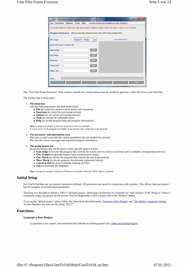
The "Cine Film Frame Extractor" main window controls the various actions that are needed to generate a video file from a cine film film.
The window has 3 major parts:
1. The menu bar with the following menus and their menu items:
� File (to contol the session actions and to select projects) � Functions (to contol the processing actions) � Options (to set various processing options) � Tools (to invoke the embedded tools) � Help (to invoke program help and program information)
Note: As long as no project is selected, some menu items are disabled. If a new version of the program is available on the internet, this is indicated in the menu bar.
2. The parameter and information area. This area is used to provide the control parameters that are needed for a project. The area also shows messages and important progress information.
3. The action button bar shows the buttons that can be used to select specific project actions.
� Scan strips (to invoke the program that controls the scanner device used to scan strips and if available a transportation device.) � Gen. Frames (to generate frames from scanned movie strips) � Gen. Movie (to invoke the program that controls the movie generation) � Show Movie (to invoke program that presents a generated movie) � Cancel Action (to stop a currently ongoing activity) � Exit (to terminate the program)
Note: as long as no project is selected, all buttons are disabled. Only the "EXIT" button is enabled.
Initial Setup
For CineToVid there are no common parameters defined. All parameters are stored in conjunction with a project. That allows, that each project has it's complete set of individual parameters.
Therefore it is desirable to define a "DFLT" (default) project, which than can function as a template for "real" projects. If the "Projects" folder is completely empty (no project ini file exists) CineToVid generates a DFLT project file in the "Projects" folder.
To set up the "default project" please follow the instructions described under "Generate a New Project" and "The Define Commands Dialog". As base filename you may use the string "DFLT".
Functions:
Generate a New Project
To generate a new project, you must have first selected an existing project (see: Open an Existing Project),
Seite 5 von 23Cine Film Frame Extractor
07.01.2011file://C:\Program Files\CineToVid\Help\CineToVid_en.htm
that will be used as template to copy the most important parameters. During the first usage of CineToVid after the installation a DFLT project with a minimum set of parameters is created. This DFLT project should be adjusted to your personal needs before creating your own projects. After that you have to klick in the File Menu onto the entry "Create New Project from Existing One". In the "Create New Project" window, that opens, the following entries have to be provided.
1. Enter a 4 character long project id into field "New Base Project Id". It is good practice to use a code that has some relation to the content of your project. That eases future project selections.
2. Enter an up to 24 character long project designation ("project description") , which shall further ease the identification of your project in the project selection dialog.
With button "Quit" the action can be cancelled, with button "Return" the new project will be opened. The parameters of the new project mays have to be adjusted in the main window.
Remarks:
A new Project INI File is created in the CineToVid/Projects folder. A Project INI File is a standard textfile that can be edited with a normal text editor (e.g. Windows Notepad).
If in the template ini file the names of the Strip-, Frame-, or Video-directories are already provided, the these entries are modified and the files are created if they do not already exist.
Modify a Project
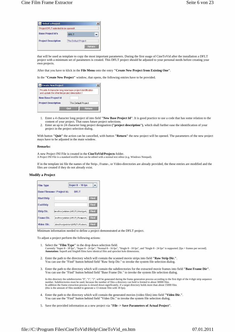
Minimum information needed to define a project demonstrated at the DFLT project.
To adjust a project perform the following actions:
1. Select the "Film Type" in the drop down selection field. Currently "Super 8 - 18 fps", "Super 8 - 24 fps", "Normal 8 - 16 fps", "Single 8 - 18 fps", and "Single 8 - 24 fps" is supported. [fps = frames per second]. Annotation: Super8 and Single8 films have identical film and sprocket hole dimensions.
2. Enter the path to the directory which will contain the scanned movie strips into field "Raw Strip Dir." . You can use the "Find" button behind field "Raw Strip Dir." to invoke the system file selection dialog.
3. Enter the path to the directory which will contain the subdirectories for the extracted movie frames into field "Base Frame Dir" . You can use the "Find" button behind field "Base Frame Dir." to invoke the system file selection dialog. In this directory the subdirectories "0", "1", "2", will be generated during the frame generation process according to the first digit of the 4 digit strip sequence number. Subdirectories must be used, because the number of files a directory can hold is limited to about 30000 files. In addition the frame extraction process is slowed down significantly, if a target directory holds more than about 15000 files (this is the amount of files needed to generate a 13 minute film with 18 fps).
4. Enter the path to the directory which will contain the generated movies (video files) into field "Video Dir." . You can use the "Find" button behind field "Video Dir." to invoke the system file selection dialog.
5. Save the provided information as a new project via "File -> Save Parameters of Actual Project".
Seite 6 von 23Cine Film Frame Extractor
07.01.2011file://C:\Program Files\CineToVid\Help\CineToVid_en.htm
Notes:
A "Open Project ...." menu item will be generated under the File menu and a project ini file will be generated in the CineToVid/Projects directory. A project ini file is a standard text file which can be edited with a standard text editor like MS Notepad if required.
If a specified strip-, frame-, or video-directory does not exist, it will be created.
If you first invoke an existing project via "File->Open Project xxxx" (xxxx e.g. DFLT), and then change the base filename (project name) you can use the values of this source project.
To define the programs, which have to be used to do the scanning, movie generation, and the movie presentation, you have to complete "The Define Commands Dialog".
The Define Commands Dialog
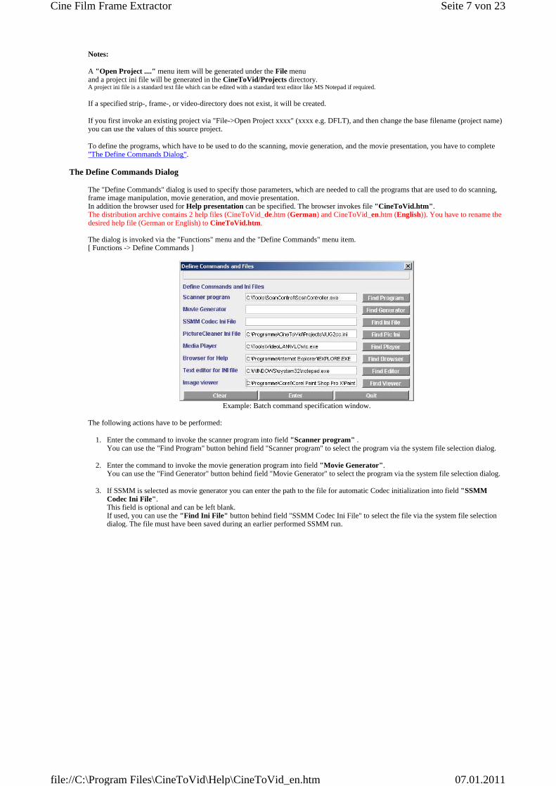
The "Define Commands" dialog is used to specify those parameters, which are needed to call the programs that are used to do scanning, frame image manipulation, movie generation, and movie presentation. In addition the browser used for Help presentation can be specified. The browser invokes file "CineToVid.htm" . The distribution archive contains 2 help files (CineToVid_de.htm (German) and CineToVid_en.htm (English)). You have to rename the desired help file (German or English) to CineToVid.htm . The dialog is invoked via the "Functions" menu and the "Define Commands" menu item. [ Functions -> Define Commands ]
Example: Batch command specification window.
The following actions have to be performed:
1. Enter the command to invoke the scanner program into field "Scanner program" . You can use the "Find Program" button behind field "Scanner program" to select the program via the system file selection dialog.
2. Enter the command to invoke the movie generation program into field "Movie Generator" . You can use the "Find Generator" button behind field "Movie Generator" to select the program via the system file selection dialog.
3. If SSMM is selected as movie generator you can enter the path to the file for automatic Codec initialization into field "SSMM Codec Ini File" . This field is optional and can be left blank. If used, you can use the "Find Ini File" button behind field "SSMM Codec Ini File" to select the file via the system file selection dialog. The file must have been saved during an earlier performed SSMM run.
Seite 7 von 23Cine Film Frame Extractor
07.01.2011file://C:\Program Files\CineToVid\Help\CineToVid_en.htm
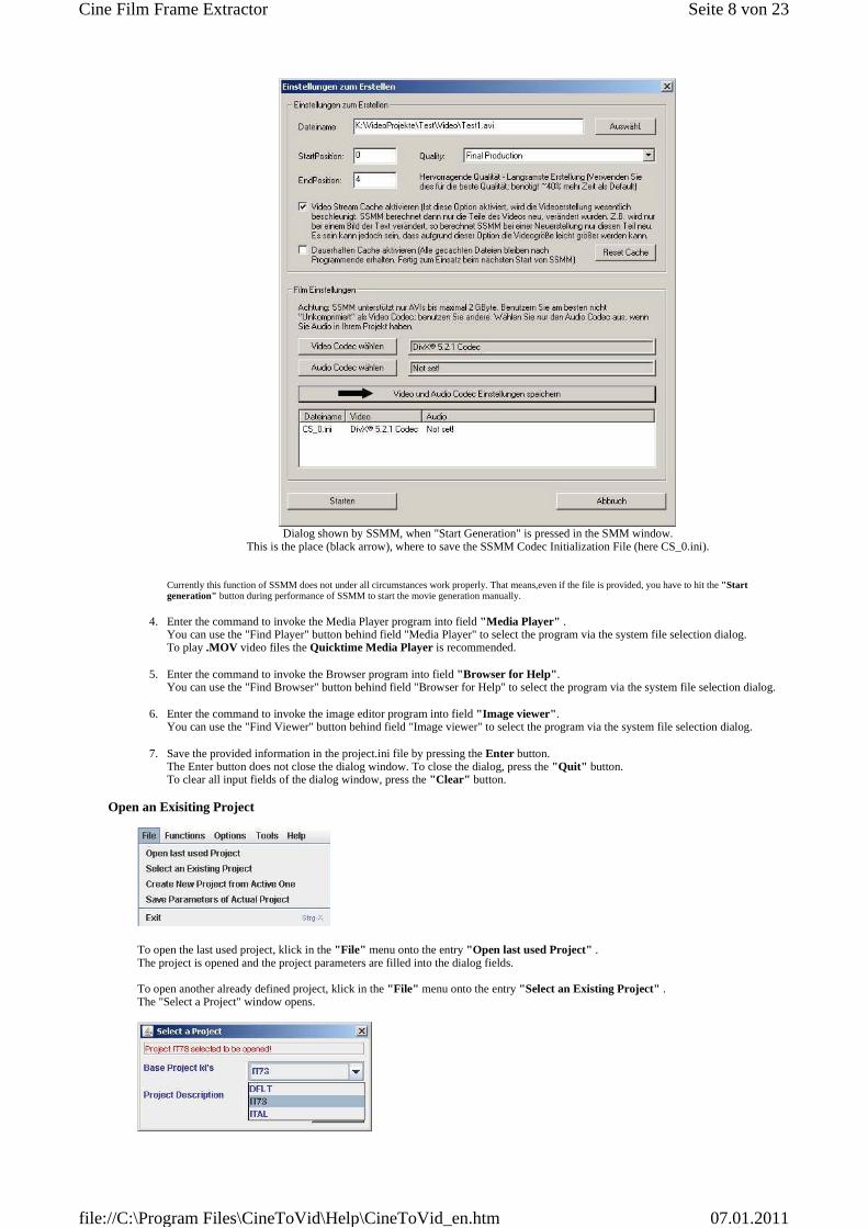
Dialog shown by SSMM, when "Start Generation" is pressed in the SMM window.
This is the place (black arrow), where to save the SSMM Codec Initialization File (here CS_0.ini).
Currently this function of SSMM does not under all circumstances work properly. That means,even if the file is provided, you have to hit the "Start generation" button during performance of SSMM to start the movie generation manually.
4. Enter the command to invoke the Media Player program into field "Media Player" . You can use the "Find Player" button behind field "Media Player" to select the program via the system file selection dialog. To play .MOV video files the Quicktime Media Player is recommended.
5. Enter the command to invoke the Browser program into field "Browser for Help" . You can use the "Find Browser" button behind field "Browser for Help" to select the program via the system file selection dialog.
6. Enter the command to invoke the image editor program into field "Image viewer" . You can use the "Find Viewer" button behind field "Image viewer" to select the program via the system file selection dialog.
7. Save the provided information in the project.ini file by pressing the Enter button. The Enter button does not close the dialog window. To close the dialog, press the "Quit" button. To clear all input fields of the dialog window, press the "Clear" button.
Open an Exisiting Project
To open the last used project, klick in the "File" menu onto the entry "Open last used Project" . The project is opened and the project parameters are filled into the dialog fields. To open another already defined project, klick in the "File" menu onto the entry "Select an Existing Project" . The "Select a Project" window opens.
Seite 8 von 23Cine Film Frame Extractor
07.01.2011file://C:\Program Files\CineToVid\Help\CineToVid_en.htm
By selecting an entry in the "Base Project Id's" pull down list field the project designation will be shown and the selected project will be openend. By klicking onto the "Return" button you go back to the main window.
Update the INI File of an Open Project
to update the values stored in the projects INI file klick in the "File" Menu onto entry "Save Parameters of Actual Project" . This forces an update of the INI file and by this guarantees, that all actually active values of the project are stored for future usage.
Scan Movie Strips
To scan film strips insert the film into the scanner so, that the sprocket holes either are at the bottom and the first frame is at the right border of the scanning area or the sprocket holes are at the top and the first frame is at the left border of the scanning area. When defining the extraction parameters you have to specify the direction in which the film is pulled through the scanner in row "Strip Transportation -> transportation direction to the ..." . You always have to scan the films horizontally (parallel to the short side of the scanners transparency unit). If you insert the film vertically (parallel to the long side of the scanners transparency unit) your film will cover parts of the calibration area at the top of the scan area, which will result in wrong colors and under- or overexposed scans.
Press the "Scan Strips" button or the "Functions -> Scan Strips" menu item to start the program, that controls the scanner. If no twain driver (e.g. EpsonScan) is specified, but the utility program "ScanController" to control both, a transportation device and a twain driver, than the ScanControl Parameter Modification Dialog opens to set the parameters for this program.
Important hint: If the scanner software allows the selection of an option named "progressive", please do not activate this option. Progressive means in this context, that the images are scanned in such a manner, that they can be used (displayed) even if not yet fully loaded. CineToVid can not evaluate the correct image size (image width and image height) because the relevant fields in the JPEG image header have not been filled (correctly) by the scanner program.
Scanning in principle is an offline process. The information about the target directory to receive the scanned strips, the naming conventions for the scanned strips (see: General Remarks ), as well as the scanning area must be provided to the scanner control program (e.g. EpsonScan) via the means offered by this program. It cannot be transferred automatically from the CineToVid project ini file to this program, because the scanner (twain) programs do not provide a standardized interface.
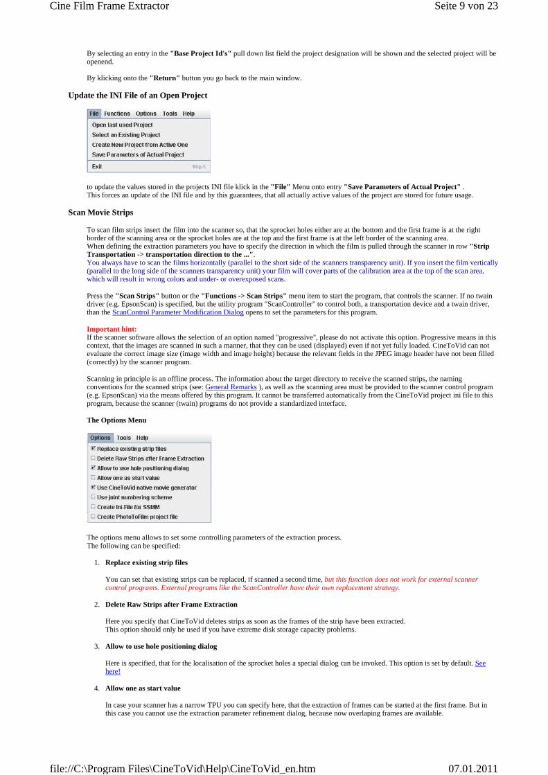
The Options Menu
The options menu allows to set some controlling parameters of the extraction process. The following can be specified:
1. Replace existing strip files
You can set that existing strips can be replaced, if scanned a second time, but this function does not work for external scanner control programs. External programs like the ScanController have their own replacement strategy.
2. Delete Raw Strips after Frame Extraction
Here you specify that CineToVid deletes strips as soon as the frames of the strip have been extracted. This option should only be used if you have extreme disk storage capacity problems.
3. Allow to use hole positioning dialog
Here is specified, that for the localisation of the sprocket holes a special dialog can be invoked. This option is set by default. See here!
4. Allow one as start value
In case your scanner has a narrow TPU you can specify here, that the extraction of frames can be started at the first frame. But in this case you cannot use the extraction parameter refinement dialog, because now overlaping frames are available.
Seite 9 von 23Cine Film Frame Extractor
07.01.2011file://C:\Program Files\CineToVid\Help\CineToVid_en.htm
(See: The "Adjust Extraction Parameters" dialog).
5. Use CineToVid native movie generator
This option is set by default. Diese Vorgabe ist standardmäßig angeschaltet. If you want to exploit a different program, you have to remove this checkmark.
6. Use joint numbering scheme
This option specifies, that the extracted frames are numbered joined consecutive, so that the frames can be used also for programs like AviDemux or VirtualDub .
7. Create Ini-File for SSMM
This option causes, that the Ini-File for SSMM is generated in the library specified via the second program invocation parameter.
8. Create PhotoToFilm project file
This option causes, that the project file for PhotoToFilm is generated.
Invocation of ScanController to start a transportation device and a twain driver.
The dialog to define the invocation parameters of the ScanController opens, if the scanner program in the "Define Commands" dialog is set to ScanController.exe.
Via this dialog the target library for the scanned film strips, the project name, and a start strip number is submitted to the ScanController. I addition the number of strips to be scanned and be set, and you can determine, whether ScanController should shut down your computer or not when scanning is completed. Caution: ScanController always overrides existing strips with identical strip id.
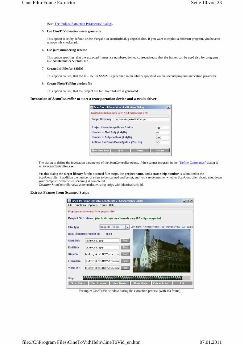
Extract Frames from Scanned Strips
Example: CineToVid window during the extraction process (with 4:3 frame).
Seite 10 von 23Cine Film Frame Extractor
07.01.2011file://C:\Program Files\CineToVid\Help\CineToVid_en.htm
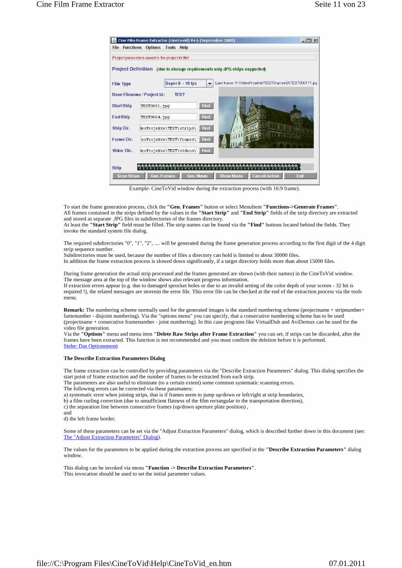
Example: CineToVid window during the extraction process (with 16:9 frame).
To start the frame generation process, click the "Gen. Frames" button or select MenuItem "Functions->Generate Frames". All frames contained in the strips defined by the values in the "Start Strip" and "End Strip" fields of the strip directory are extracted and stored as separate .JPG files in subdirectories of the frames directory. At least the "Start Strip" field must be filled. The strip names can be found via the "Find" buttons located behind the fields. They invoke the standard system file dialog.
The required subdirectories "0", "1", "2", .... will be generated during the frame generation process according to the first digit of the 4 digit strip sequence number. Subdirectories must be used, because the number of files a directory can hold is limited to about 30000 files. In addition the frame extraction process is slowed down significantly, if a target directory holds more than about 15000 files.
During frame generation the actual strip processed and the frames generated are shown (with their names) in the CineToVid window. The message area at the top of the window shows also relevant progress information. If extraction errors appear (e.g. due to damaged sprocket holes or due to an invalid setting of the color depth of your screen - 32 bit is required !), the related messages are storenin the error file. This error file can be checked at the end of the extraction process via the tools menu.
Remark: The numbering scheme normally used for the generated images is the standard numbering scheme (projectname + stripnumber+ famenumber - disjoint numbering). Via the "options menu" you can specify, that a consecutive numbering scheme has to be used (projectname + consecutive framenumber - joint numbering). In this case programs like VirtualDub and AviDemux can be used for the video file generation. Via the "Options" menu and menu item "Delete Raw Strips after Frame Extraction" you can set, if strips can be discarded, after the frames have been extracted. This function is not recommended and you must confirm the deletion before it is performed. Siehe: Das Optionsmenü
The Describe Extraction Parameters Dialog
The frame extraction can be controlled by providing parameters via the "Describe Extraction Parameters" dialog. This dialog specifies the start point of frame extraction and the number of frames to be extracted from each strip. The parameters are also useful to eliminate (to a certain extent) some common systematic scanning errors. The following errors can be corrected via these paramaters: a) systematic error when joining strips, that is if frames seem to jump up/down or left/right at strip boundaries, b) a film curling correction (due to unsufficient flatness of the film rectangular to the transportation direction), c) the separation line between consecutive frames (up/down aperture plate position) , and d) the left frame border.
Some of these parameters can be set via the "Adjust Extraction Parameters" dialog, which is described further down in this document (see: The "Adjust Extraction Parameters" Dialog).
The values for the parameters to be applied during the extraction process are specified in the "Describe Extraction Parameters" dialog window.
This dialog can be invoked via menu "Function -> Describe Extraction Parameters". This invocation should be used to set the initial parameter values.
Seite 11 von 23Cine Film Frame Extractor
07.01.2011file://C:\Program Files\CineToVid\Help\CineToVid_en.htm
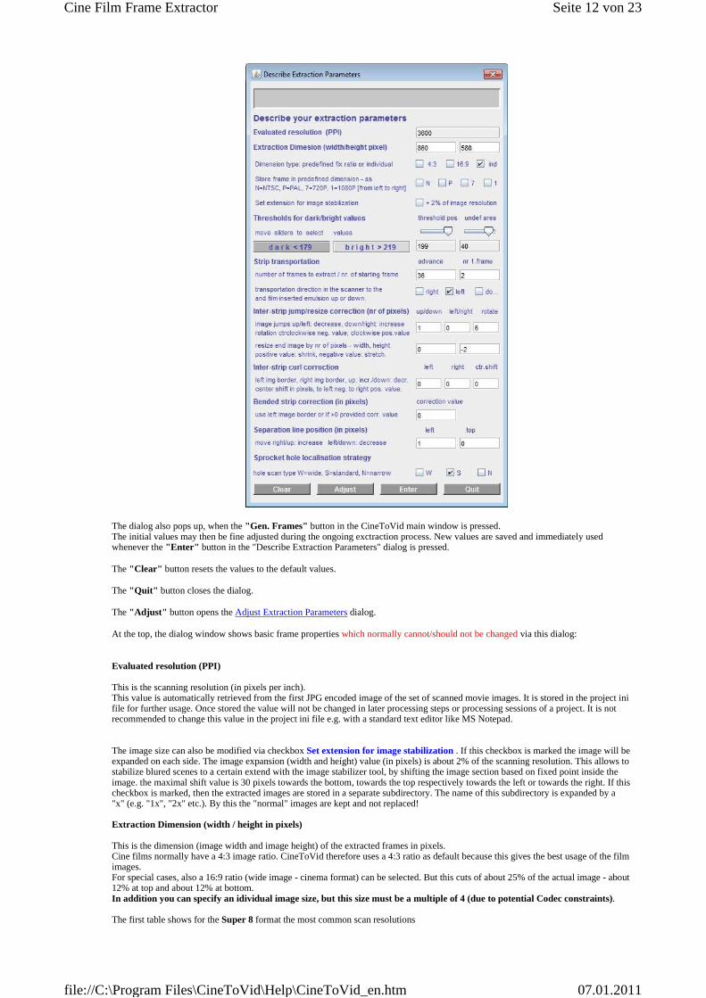
The dialog also pops up, when the "Gen. Frames" button in the CineToVid main window is pressed. The initial values may then be fine adjusted during the ongoing exctraction process. New values are saved and immediately used whenever the "Enter" button in the "Describe Extraction Parameters" dialog is pressed.
The "Clear" button resets the values to the default values.
The "Quit" button closes the dialog.
The "Adjust" button opens the Adjust Extraction Parameters dialog.
At the top, the dialog window shows basic frame properties which normally cannot/should not be changed via this dialog:
Evaluated resolution (PPI)
This is the scanning resolution (in pixels per inch). This value is automatically retrieved from the first JPG encoded image of the set of scanned movie images. It is stored in the project ini file for further usage. Once stored the value will not be changed in later processing steps or processing sessions of a project. It is not recommended to change this value in the project ini file e.g. with a standard text editor like MS Notepad. The image size can also be modified via checkbox Set extension for image stabilization . If this checkbox is marked the image will be expanded on each side. The image expansion (width and heíght) value (in pixels) is about 2% of the scanning resolution. This allows to stabilize blured scenes to a certain extend with the image stabilizer tool, by shifting the image section based on fixed point inside the image. the maximal shift value is 30 pixels towards the bottom, towards the top respectively towards the left or towards the right. If this checkbox is marked, then the extracted images are stored in a separate subdirectory. The name of this subdirectory is expanded by a "x" (e.g. "1x", "2x" etc.). By this the "normal" images are kept and not replaced! Extraction Dimension (width / height in pixels)
This is the dimension (image width and image height) of the extracted frames in pixels. Cine films normally have a 4:3 image ratio. CineToVid therefore uses a 4:3 ratio as default because this gives the best usage of the film images. For special cases, also a 16:9 ratio (wide image - cinema format) can be selected. But this cuts of about 25% of the actual image - about 12% at top and about 12% at bottom. In addition you can specify an idividual image size, but this size must be a multiple of 4 (due to potential Codec constraints). The first table shows for the Super 8 format the most common scan resolutions
Seite 12 von 23Cine Film Frame Extractor
07.01.2011file://C:\Program Files\CineToVid\Help\CineToVid_en.htm

and the assiciasted frame dimensions (all values in pixels) . Recommended values are shown in blue.
The second table shows for the Normal 8 format the most common scan resolutions and the assiciated frame dimensions (all values in pixels) . Recommended values are shown in blue.
For scan resolutions outside the specified ranges the image extraction dimensions are derived from the physical image measurements (see Set Physical Film Measurements).
The following extraction parameters can be set respectively changed:
Store frames in predefined dimension
It is possible to store the extracted frames in a predefined dimension. If no predefined dimension is checked, then the frames are stored in the extraction dimension. These predefined dimensions are: a) 640x480 Pixel (according to the NTSC televison standard - Checkbox N selectedt) b) 720x576 Pixel ((according to the DVD - PAL televison standard - Checkbox P selected) c) 1280x720 Pixel ((according to the 720p televison standard - Checkbox 7 selected) d) 1920x1080 Pixel ((according to the 1080p televison standard - Checkbox 1 selected) If in addition to the predefined sizes of 720p or 1080p a ratio of 4:3 is selected, the frames are expanded with a black bar to the left and right to keep the original ratio of the frames. See examples (left: adjusted image in the 16:9 format and right: full image in the 4:3 format with black borders):
Scan resolution frame width 4:3 frame height 4:3 frame width 16:9 frame height 16:9
3200 to 3399 680 510 688 387
3400 to 3499 720 540 720 405
3500 to 3599 736 552 736 414
3600 to 3699 720 576 720 442
3700 to 3799 768 576 768 442
3800 to 3899 800 600 800 450
3900 to 4099 848 636 848 477
4100 to 4399 880 660 880 495
4400 to 4799 960 720 960 540
4800 to 6399 1012 760 1016 572
6400 to 7199 1376 1032 1376 774
> 7199 1536 1152 1536 864
Scan resolution frame width 4:3 frame height 4:3 frame width 16:9 frame height 16:9
3200 to 3399 560 420 560 316
3400 to 3499 600 450 600 336
3500 to 3599 624 464 624 350
3600 to 3699 640 480 640 360
3700 to 3899 672 504 672 376
3900 to 4099 704 524 704 392
4100 to 4399 720 540 720 404
4400 to 4799 784 588 784 440
4800 to 4999 856 640 856 480
Seite 13 von 23Cine Film Frame Extractor
07.01.2011file://C:\Program Files\CineToVid\Help\CineToVid_en.htm

Annotation: During projection expanded frames will very likely show a moving left and right image border if the film scenes are smoothed with a video editor or a deshaker filter, because these filters normally move the frame content (depending on the preceeding and following frames) slightly up or down and left or right in order to achieve a more stabil scene impression. Threshold for dark/bright values
The values for dark/bright detection determine, from which color value a pixel is considered to be dark or bright. The RGB (red green blue) color components of a pixel must be below (dark) or above (bright) the specified value. All colors above the bright value are considered to be bright , all colors below the dark value are considered to be dark . Via the left slider the position between dark and bright can be specified. Via the right slider the width of the undefined area is set. The actual threshold value is calculated from the left slider position plus (bright) respectively minus (dark) half of the value specified for the width of the undefined area. The width of the undefined zone must be between 10 and 50. Hint: If during frame extraction the upper respectivly the lower image border is moving up or down, most likely the sprocket hole detection is not sufficiently exact. A modification of the dark/bright values normally helps. Strip transportation and film emulsion positioning
The strip tranportation specifies, how many useable frames are contained in one strip and which frame is the first frame to be extracted from the strip. Advance therefore specifies the useable length of a piece of the film (in pictures) which has been transported by a single pulling action with the transport mechanism of the film advancing tool during the scanning process. It differs from the physical lenght of the strip, which mainly depends on the width of the transparency unit of the exploited scanner. nr 1.frame determines, which (complete) frame (calculated from the beginning of the strip starting with 1) has to be extracted as the first frame. This number must normally be larger than 1, but in special cases you can allow the value 1 (non overlapping strips). For that the option "Allow one as start value" must have been selected in the Options Menu. If that is the case, you cannot use the dialog supporting the parameter value setting, because this dialog needs overlapping strips. Hint: If during frame extraction a message appears, that tells you, that an image is not completely inside the strip most likely the number of frames is wrong or the starting position is incorrect. The transport direction of the film through the scanner is specified via the check marks to left [sprocket holes at top] or to right [sprocket holes at bottom]. (Target reel left (sprocket holes at top) = left, target reel right (sprocket holes at bottom) = right). Here you can in addition specify, that the film has been inserted in such a way, that the emulsion is down towards the scanner glass. The scan result in this case will be a mirrored strip. That means, that the sprocket holes are at bottom if transport direction is to the left and at top, if transport direction is to the right. During frame extraction the strip is mirrored again, so that the frames appeare correctly. Interstrip jump/resize correction (nr of pixels)
These are correction values (number of pixels) which have to be applied during the frame extraction in order to eliminate a potential jump effect between the last extracted frame of strip n and the first extracted frame of strip n+1. Due to a slight parallaxe a scanner "sees" the frames and sprocket holes not in identical size over the full strip width and this causes the jumps. This systematical error does not bother when still images (slides) are scanned, but are recognized very well if a sequence of movie frames are projected. The first (left) value is used to correct the vertical positioning. The second (center) value is used to correct the horizontal positioning. The third (right) value is used to correct a image rotation. The fourth (lower right) value is used to correct image width. The fifth (lower left) value is used to correct a image height. If (at strip boundaries) the pictures seem to jump up or to the left, decrease the number, if the pictures seem to jump down or to the right increase the number. Positive and negative values are allowed. For the rotation correction a negative value means a counterclockwise rotation, a positive value causes a clockwise rotation of the frame. Advice: to find out the jump direction place the mouse pointer onto a significant detail of the picture shown in the extracted frame pane and try to estimate, how many pixels may be needed to make this detail to stay at the same position on frames extracted from consecutive strips. Inter-strip curl correction (in pixels)
Film material always curls rightangular to the transportation direction [film material on acetate basis (Kodak, Agfa, Perutz ...) less, film material on polyester basis (Fuji) significantly more]. This curling is the main reason for periodically jumping picture borders at positions, where 2 strips are joined, because the curling value at the begin and the end of a strip may be different. Even a very precisely crafted film holder cannot avoid this curling completely. Due to this reason CineToVid offers an inter strip curling correction, which can be applied at the beginning or at the end of scanned strip in order to compensate this curling effect at least to a certain percentage. Via the check marks "begin" , "end" or "both" is determined, at which strip end the correction shall be applied. Default value is "both" . The leftmost ans rightmost input fields allow to set the correction value at the left image border, and at the right image border. The 2 center input fields determines the number of frames that have to be corrected and the shift of the image center (to the right = positive
Seite 14 von 23Cine Film Frame Extractor
07.01.2011file://C:\Program Files\CineToVid\Help\CineToVid_en.htm

value, to the left = negative value) for the curl compensation calculation. If both ends are corrected at each side half of the value of the third input filed is used. The image will be corrected in X-direction (width) continuously. The correction value (y position) is a function of the x position of the pixel in the image. See The "Adjust Extraction Parameters" Dialog. Bended strip correction (in pixels)
It might happen, that the film holder is not 100 % straight. This results in a slightly bended strip and this causes a small rhytmic swinging of the image from left to right and from right to left (like a pendulum). To correct this swinging, the frames are extracted based on the inner border of the sproket hole (transportation hole). If the correction is set to a value other than 0 (zero) than not the inner border of the sprocket hole is used, but the value is treated as deviation from the straight line between the first and last sprocket hole of the strip in the middle of the strip. The positions of the left image borders of the individual frames are interpolated in a linear manner. This approach can be used, if the inner border of the sprocket hole is difficult to detect (because the window in the film camera used to expose the film is relatively wide - right example image below - and therefore there is no black line between image and sprocket hole - see left example in the picture below ). Positive and negative values are allowed. Positive means the center of the sprocket hole in the middle of the strip is (relative to the straight connection line) towards the frame, negative means it is towards the film border.
Example Images
Separation line position (in pixels)
The first value is used to move the separation line between sound track and image from left to right and vice versa. If the image border has to be moved to the right , increase the value, if it has to be moved to the left, decrease the value. Positive and negative values are allowed. The second value is used to move the separation line between frames from top to bottom and vice versa - aperture mask up/down positioning. If the image border has to be moved up, increase the value, if it has to be moved down, decrease the value. Positive and negative values are allowed. Sprocket hole localisation strategy
Strips cannot be scanned in their accurate width and it is also impossible to position the film accurately horizontal in the scanner. Therefore the positions of the frames in a strip must be evaluated by using the sprocket holes of the film. The position of the first full sprocket hole at the left strip border is evaluated by scanning the strip for the borders of dark and bright areas. The detection of the sprocket holes is supported by a dialog, which allows in the first strip to be scanned to mark the center of a sprocket hole with the mouse pointer. To bring up this dialog in the Options Menu the "Allow to use Positioning Dialog" entry must be activeted. For the detection strategy you can in addition specify the width of the band, that is used to find the sprocket hole edges. For "W" (wide) 40%, for "S" (standard) 30%, and for "N" (narrow)" 20% of the width of the sprocket hole is used. Scanning is done in the inner part, the part that is closer to the image. If the sprocket holes are partially covered by the film guide you should take care, that a minimum of 50% of the width of the sprocket hole is visible. The following pictures show a simple format holder made from card board with a glass pane (slightly structured towards the film to fight Newton-Rings) and an advanced film holder milled from alluminum that allows easy removal of the film. When inserting the film holder into the flatbed scanner you must take care, that the calibration area at the top of the scanner is not covered. If it is (even partially) covered, you get inaccurately scanned strips (false colors or too bright).
A simple format holder made from card board with a glass pane to keep the film flat.
Seite 15 von 23Cine Film Frame Extractor
07.01.2011file://C:\Program Files\CineToVid\Help\CineToVid_en.htm
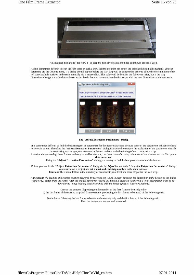
An advanced film guide ( top view ) - to keep the film strip plain a moulded alluminum profile is used.
As it is sometimes difficult to scan the film strips in such a way, that the program can detect the sprocket holes in all situations, you can determine via the Options menu, if a dialog should pop up before the start strip will be extracted in order to allow the determination of the left sprocket hole position in the strip manually via a mouse click. This value will be kept for the follow up strips, but if the strip dimensions change, the value has to be set again. To do that you have to name the first strips with the new dimensions as the start strip.
The "Adjust Extraction Parameters" Dialog
It is sometimes difficult to find the best fitting set of parameters for the frame extraction, because some of the parameters influence others to a certain extent. Therefore the "Adjust Extraction Parameters" dialog is provided to support the evaluation of the parameters visually
by comparing two images, one extracted at the end and one at the beginning of two consecutive strips. As strips always overlap, these frames in theory should be identical, but due to manufacturing tolerances of the scanner and the film guide,
they never are. Using the "Adjust Extraction Parameters" dialog you can try to find the best possible match of the frames.
Before you invoke the "Adjust Extraction Parameters" dialog via the Adjust button in the "Describe Extraction Parameters" dialog, you must select a project and set a start and end strip number in the main window.
Caution: There must follow in the directory of scanned strips at least one more strip after the start strip.
Annotation: The loading of the strips must be triggered by pressing the "Load Images" button in the button bar at the bottom of the dialog window (2. button from the right). After the images have been loaded this button is disabled. As there is a lot of preparation work to be
done during image loading, it takes a while until the image appears. Please be patiente.
CineToVid extracts (depending on the number of the first frame to be used) either a) the last frame of the starting strip and frame 0 (frame preceeding the first frame to be used) of the following strip
or b) the frame following the last frame to be use in the starting strip and the first frame of the following strip.
Then the images are merged and presented.
Seite 16 von 23Cine Film Frame Extractor
07.01.2011file://C:\Program Files\CineToVid\Help\CineToVid_en.htm

With the buttons provided in the dialog window you now can move the second frame (the frame extracted at the beginning of the strip following the selected strip) in such a manner, that it matches the first frame as accurate as possible. But you should be aware, that a
100% match is not possible (due to the above stated reasons).
The following movements are provided: 1. Set upper image boundary (aperture mask up/down adjustment)
With the spinner buttons designated with img. pos. up down you can set the upper image boundary. The actual shift value is shown in the spinner buttons value field and the frame position is shown as a white rectangle in the image.
2. Set left image boundary (aperture mask left/right adjustment)
With the spinner buttons designated with img. pos. left right you can set the left image boundary. The actual shift value is shown in the spinner buttons value field and the frame position is shown as a white rectangle in the image.
3. Move full image vertically
With the spinner buttons designated with join corr up down , it is possible to move the second image relative to the first image vertically pixel by pixel. The actual value is shown in the spinner buttons value field.
4. Move full image horizontally
With the spinner buttons designated with join corr left right , it is possible to move the second image relative to the first image horizontally pixel by pixel. The actual value is shown in the spinner buttons value field.
5. Rotate full image clockwise or counterclockwise
With the spinner buttons designated with img rotate cclock clock the socond image can be rotated clockwise or counterclockwise around the image center. A negative value means a counter clockwise rotation, a positive value means a
clockwise rotation. The rotation angle will be calculated from the provided pixel value. 6. Adjust image width
With the spinner buttons designated with resize end img width, it is possible to stretch or shrink the frame width by a certain number of pixels. Negative values mean stretching and positve values mean shrinking of the image. The actual value is shown
in the spinner buttons value field. 7. Adjust image height
With the spinner buttons designated with resize end img height, it is possible to stretch or shrink the frame height by a certain number of pixels. Negative values mean stretching and positve values mean shrinking of the image. The actual value
is shown in the spinner buttons value field. 8. Film curling correction
With the spinner 2 buttons at the left and the right image border at the top of the image, you can adjust the second image in vertical direction to match the first image as good as possible. The central spinner button determines, how many pixels the
center of the image should be moved to the left (negative value) or to the right (positive value) for the correction calculation. The actual correction value is shown in the spinner buttons value fields. Negative and positive values are allowed. The image
movement in y-direction is a function of the x - position of the actual image pixel column. As the film curls not necessarily symetrically, you can shift the center of the image to the left (negative value) or to the right (positive value) in order to achieve a better match of the images. A vertical white line shows the position of the image center.
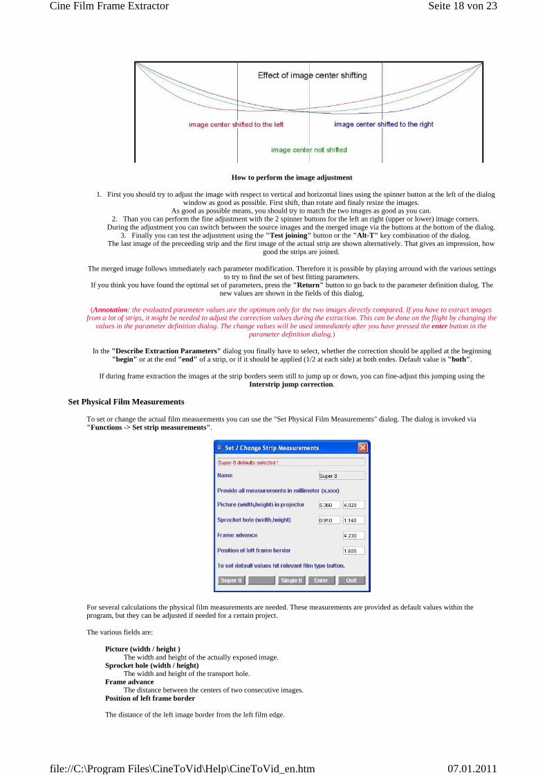
The effect of the line position you can see in the following image.
Seite 17 von 23Cine Film Frame Extractor
07.01.2011file://C:\Program Files\CineToVid\Help\CineToVid_en.htm
How to perform the image adjustment
1. First you should try to adjust the image with respect to vertical and horizontal lines using the spinner button at the left of the dialog window as good as possible. First shift, than rotate and finaly resize the images.
As good as possible means, you should try to match the two images as good as you can. 2. Than you can perform the fine adjustment with the 2 spinner buttons for the left an right (upper or lower) image corners.
During the adjustment you can switch between the source images and the merged image via the buttons at the bottom of the dialog. 3. Finally you can test the adjustment using the "Test joining" button or the "Alt-T" key combination of the dialog.
The last image of the preceeding strip and the first image of the actual strip are shown alternatively. That gives an impression, how good the strips are joined.
The merged image follows immediately each parameter modification. Therefore it is possible by playing arround with the various settings to try to find the set of best fitting parameters.
If you think you have found the optimal set of parameters, press the "Return" button to go back to the parameter definition dialog. The new values are shown in the fields of this dialog.
(Annotation: the evaluated parameter values are the optimum only for the two images directly compared. If you have to extract images
from a lot of strips, it might be needed to adjust the correction values during the extraction. This can be done on the flight by changing the values in the parameter definition dialog. The change values will be used immediately after you have pressed the enter button in the
parameter definition dialog.)
In the "Describe Extraction Parameters" dialog you finally have to select, whether the correction should be applied at the beginning "begin" or at the end "end" of a strip, or if it should be applied (1/2 at each side) at both endes. Default value is "both" .
If during frame extraction the images at the strip borders seem still to jump up or down, you can fine-adjust this jumping using the Interstrip jump correction .
Set Physical Film Measurements
To set or change the actual film measurements you can use the "Set Physical Film Measurements" dialog. The dialog is invoked via "Functions -> Set strip measurements".
For several calculations the physical film measurements are needed. These measurements are provided as default values within the program, but they can be adjusted if needed for a certain project.
The various fields are:
Picture (width / height ) The width and height of the actually exposed image.
Sprocket hole (width / height) The width and height of the transport hole.
Frame advance The distance between the centers of two consecutive images.
Position of left frame border
The distance of the left image border from the left film edge.
Seite 18 von 23Cine Film Frame Extractor
07.01.2011file://C:\Program Files\CineToVid\Help\CineToVid_en.htm
The default values are filled into the dialog input fields, when the relevant film type button (e.g. the "Super 8" button) is pressed.
Modified values are saved to the project ini file when the "Enter" button is pressed. Note: all values have to be provided as 4.3 values (4 digits with 3 decimals after the decimal point) and must represent measurements in millimeter.
The "Enter" button does not close the dialog window. To close the window, press the "Quit" button.
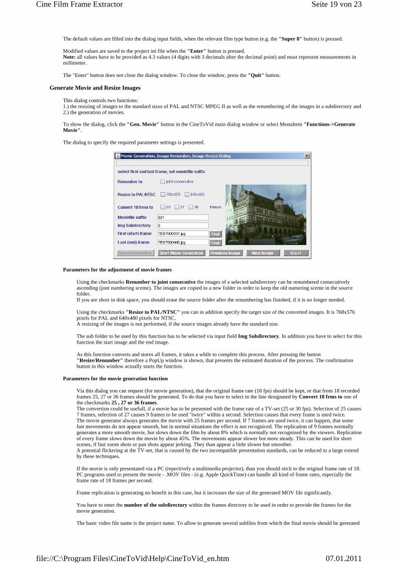
Generate Movie and Resize Images
This dialog controls two functions: 1.) the resizing of images to the standard sizes of PAL and NTSC MPEG II as well as the renumbering of the images in a subdirectory and 2.) the generation of movies. To show the dialog, click the "Gen. Movie" button in the CineToVid main dialog window or select MenuItem "Functions->Generate Movie" .
The dialog to specify the required parameter settings is presented.
Parameters for the adjustment of movie frames
Using the checkmarks Renumber to joint consecutive the images of a selected subdirectory can be renumbered consecutively ascending (jont numbering sceme). The images are copied to a new folder in order to keep the old numering sceme in the source folder. If you are short in disk space, you should erase the source folder after the renumbering has finished, if it is no longer needed.
Using the checkmarks "Resize to PAL/NTSC" you can in addition specify the target size of the converted images. It is 768x576 pixels for PAL and 640x480 pixels for NTSC. A resizing of the images is not performed, if the source images already have the standard size.
The sub folder to be used by this function has to be selected via input field Img Subdirectory. In addition you have to select for this function the start image and the end image.
As this function converts and stores all frames, it takes a while to complete this process. After pressing the button "Resize/Renumber" therefore a PopUp window is shown, that presents the estimated duration of the process. The confirmation button in this window actually starts the function.
Parameters for the movie generation function
Via this dialog you can request (for movie generation), that the original frame rate (18 fps) should be kept, or that from 18 recorded frames 25, 27 or 36 frames should be generated. To do that you have to select in the line designated by Convert 18 frms to one of the checkmarks 25 , 27 or 36 frames. The convertion could be usefull, if a movie has to be presented with the frame rate of a TV-set (25 or 30 fps). Selection of 25 causes 7 frames, selection of 27 causes 9 frames to be used "twice" within a second. Selection causes that every frame is used twice. The movie generator always generates the movie with 25 frames per second. If 7 frames are used twice, it can happen, that some fast movements do not appear smooth, but in normal situations the effect is not recogniced. The replication of 9 frames normally generates a more smooth movie, but slows down the film by about 8% which is normally not recognized by the viewers. Replication of every frame slows down the movie by about 45%. The movements appear slower bot more steady. This can be used for short scenes, if fast zoom shots or pan shots appear jerking. They than appear a little slower but smoother. A potential flickering at the TV-set, that is caused by the two incompatible presentation standards, can be reduced to a large extend by these techniques.
If the movie is only presentated via a PC (repectively a multimedia projector), than you should stick to the original frame rate of 18. PC programs used to present the movie - .MOV files - (e.g. Apple QuickTime) can handle all kind of frame rates, especially the frame rate of 18 frames per second.
Frame replication is generating no benefit in this case, but it increases the size of the generated MOV file significantly.
You have to enter the number of the subdirectory within the frames directory to be used in order to provide the frames for the movie generation.
The basic video file name is the project name. To allow to generate several subfiles from which the final movie should be gererated
Seite 19 von 23Cine Film Frame Extractor
07.01.2011file://C:\Program Files\CineToVid\Help\CineToVid_en.htm

enter a "suffix" (y) by which the video file name will be expanded. Normally you can use the subdirectory number, but any string value that generates valid file names is allowed. This allows (together with start frame and end frame selection) segmentation of the movie, if a part gets too long.
Enter the "file id" of the first frame and the last frame of the movie segment to be generated or the images that should be resized. You can use the "Find" buttons to select the frames. If entered manually, enter the full name (including the ".jpg" file extension). An image selected via the Find button is presented in the dialog window. Using the buttons Previous Image or Next Image the image selection can be fine adjusted.
If the file name suffix, the subdirectory, the start and the end image and a potentially desired frame replication rate has been selected, the film generation is started by the "Start Movie Generation" button. The generation is a rather lengthy process, so please stay patient until the movie is generated.
If you use the movie generator built into CineToVid the CineToVid generates a list of all images to be used to generate the movie. The allowed transitions are taken into account for this list generation - see Generate Transitions. Then the generation process is started. The generated Video File is an Apple Quicktime (Motion JPEG A, also known as Apple Photo JPEG or Still Image JPEG DIB) video file with file extension .MOV. Some computers have a problem with very large .MOV video files. If this is the case, the video files generated this way should not significantly exceed 110 to 120 MB. If they do, you should (based on the scene changes probably stored with the image cleaner) split up the file and generate several partial video files. The optimal file size for your system, you have to find out on your own.
If SSMM is selected as movie generator, CineToVid generates the SSMM initialization file, which is provided to SSMM during program invocation. Via the Options menu you can select, if CineToVid should also provide a predefined Codec Initialization file.
Note: it takes a very long time to initialize SSMM because SSMM does a lot of checking in the startup phase.
If you want to use SSMM to apply some special effects (title generation, transitions, omition of specific frames, etc.) you can force CineToVid to prepare the initialization file so that SSMM will generate this effects (see Generate Transitions).
If PhotoToFilm is used as movie generator, CineToVid generates a PhotoToFilm project file. Currently (February 2006) PhotoToFilm is not able to get the file via an invocation parameter. It has to be specified manually inside the PhotoToFilm program.
If you use a different program, you have to provide the control information required by this program on your own. The movie generator is used to generate the movie from the frames in the frames directory (subdirectoy). Follow the instructions of the exploited program. This program determines also the "CoDec" used for video compression. CineToVid always uses "Still Image JPEG DIB". That guarantees good quality but at the cost of a slightly bigger video file. Other programs may use other CoDecs (e.g. DivX Pro 6.1.1 (currently recommended), XviD MPEG-4 Codec, or others). Generated is a movie file with a name "xxxxy.avi" file (xxxx = project name, y = suffix). This file should be stored in the specified video directory.
Generate Transitions
Transitions are specifications how consecutive pictures merge. Standard transition for CineToVid is a hard transition, that is frame n+1 directly follows frame n (repetiton factor is 1) without merging. But you also can specify that a frame should fade in and fade out or dissolve to the next frame. But this is only possible, if a frame is repeated several times and by that of course increases the presentation time of a movie.
The CineToVid native movie generation (similar as PhotoToFilm) does not support smooth transitions and title generation. Supported is only frame repetition (slow motion), frame skipping and reverse projection. CineToVid assumes, that transitions and titles are generated with video editing programs. All of them can do that easily and conveniently.
(For details about the possible effects please refer to the SSMM documentation - but keep in mind, that CineToVid only implements a subset of the effects offered by SSMM. For experienced users: you can define your own subset of available transition types if you manually modify the value for "Transition =" in the project's ini file.)
Select menu item "Functions -> Generate Transitions" to invoke the "Set Transitions" dialog.
Seite 20 von 23Cine Film Frame Extractor
07.01.2011file://C:\Program Files\CineToVid\Help\CineToVid_en.htm

The "Set Transitions" dialog can be used to prepare some special effects SSMM can perform in the SSMM initialization file. Transitions are saved in the project ini file and are used always when the SSMM initialization file is generated during a "generate movie" action. Possible is:
1. to repeat a specific image multiple times 2. to exclude a specific image or a sequence of images 3. to set the transition type and length for repeated images
Examples:
To prepare a title perform the following:
1. Select an image, that should function as title background. 2. With an image editor (PhotoShop, PaintShop Pro, IrfanView) insert the title into the image. 3. Store the image in the frames directory. 4. In the "Set Transition" dialog set the "Base Frame Directory" and the "Subdirectory Number" . 5. Provide the image file name. 6. Set image repetition count (number of frames to display). This determines the time, how long the title will be displayed. 18
frames represent 1 seconde (for Super 8 18 fps). This count does not include the frames needed for the transition. 7. Set image transition count (nr of frames for transition ). This determines the time, how long the transition to the next frame
will last. 18 frames represent 1 seconde (for Super 8 18 fps). 8. Select the transition type (SSMM transition types ) 9. Press the "Add to list" button to insert the entry at the end of the list of generated transition specifications.
To handle a sequence of images perform the following:
1. In the "Set Transition" dialog set the "Base Frame Directory" and the "Subdirectory Number" . 2. Provide the starting image file name and the ending image file name separated by the string " - " (blank minus blank).
You can use the "Find" button two times. The separation string is inserted automatically, if you select the frames with the "Find" button. If you enter the frame identifications manually, you must enter the full file names (including the ".jpg" file extension).
3. Set image repetition count (number of frames to display) to zero or the desired number. 4. Set image transition count (nr of frames for transition )to zero or the desired number. 5. Select any transition type (SSMM transition types) 6. Press the "Add to list" button to insert the entry at the end of the list of generated transition specifications.
Hint: The generation of transitions via the dialog may become a little awkward if a lot of transitions are needed. A more efficient way to insert the required transition entries into the ini file is to use an editor (like MS notepad). You can generate some samples with the dialog, then use cut and paste to duplicate the entries and finally adjust these duplicated entries.
The Special Transition "Reverse"
CineToVid normally generates a input file for the "movie generator" in which the images are presented in the sequence as they appear in the frames library. In this file for each image only a single transition specification is allowed.
To allow also reverse projection for specific scenes the special transition "Reverse" has been introduced. With this transition the images of a scene (defined by the start frame and the end frame) will be presented in reverse sequence to the movie generator. Because there is only one transition for an image allowed, this makes it impossible to generate the scene with both projection types (foreward and backward) in a single generation process.
If - due to dramaturgic reasons - both directions should be used, it is necessary to perform 2 generation runs. In the first run the normal forward projection (of the whole movie) is generated and in the seceond run only the isolated scene is generated in backward projection. The "Reverse" transition must be disabled (commented out or removed) for the first run in the "ini file". For the second run, in which the relevant start and end image is specified and in which in addition a new Moviefile Suffix must be provided in the " Select Frame Area" dialog, the entry must be activated again.
Seite 21 von 23Cine Film Frame Extractor
07.01.2011file://C:\Program Files\CineToVid\Help\CineToVid_en.htm
The scene generated in this manner can then be inserted into the movie at the desired place later on by using the video editor (e.g. Magix Video Editor, Adobe Premiere Elements, Pinnacle Studio or even VirtualDub).
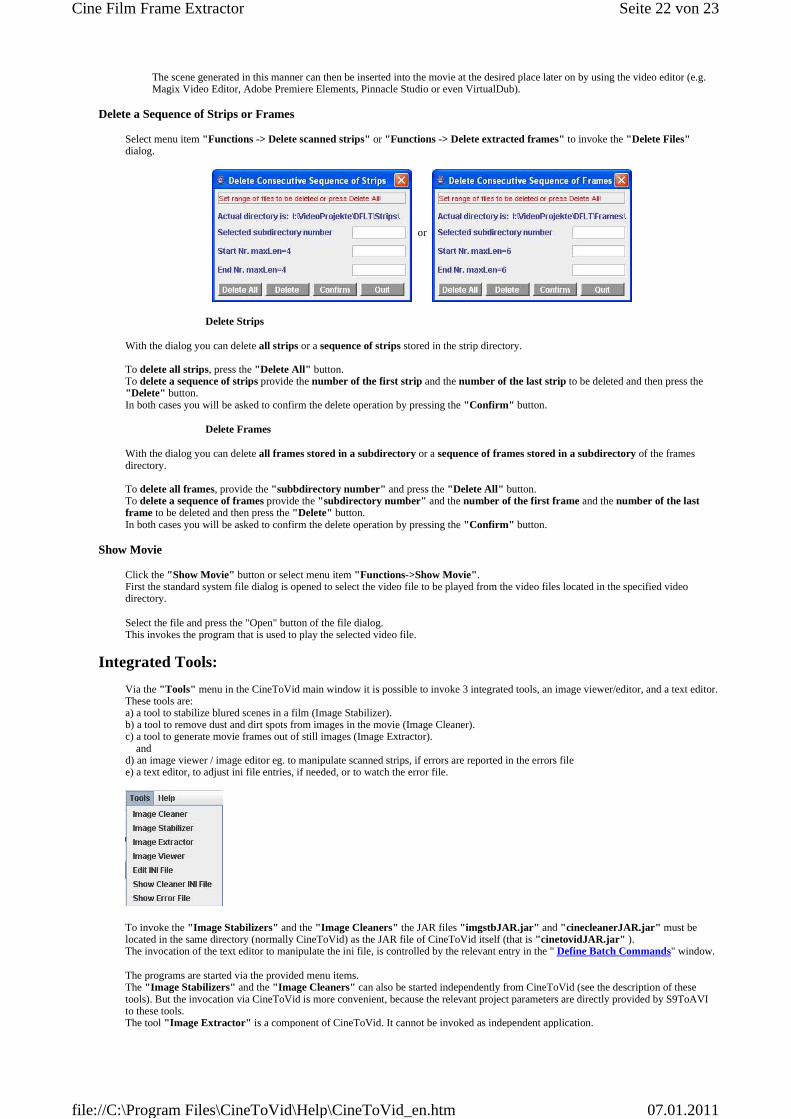
Delete a Sequence of Strips or Frames
Select menu item "Functions -> Delete scanned strips" or "Functions -> Delete extracted frames" to invoke the "Delete Files" dialog.
or
Delete Strips
With the dialog you can delete all strips or a sequence of strips stored in the strip directory. To delete all strips, press the "Delete All" button. To delete a sequence of strips provide the number of the first strip and the number of the last strip to be deleted and then press the "Delete" button. In both cases you will be asked to confirm the delete operation by pressing the "Confirm" button.
Delete Frames
With the dialog you can delete all frames stored in a subdirectory or a sequence of frames stored in a subdirectory of the frames directory. To delete all frames, provide the "subbdirectory number" and press the "Delete All" button. To delete a sequence of frames provide the "subdirectory number" and the number of the first frame and the number of the last frame to be deleted and then press the "Delete" button. In both cases you will be asked to confirm the delete operation by pressing the "Confirm" button.
Show Movie
Click the "Show Movie" button or select menu item "Functions->Show Movie". First the standard system file dialog is opened to select the video file to be played from the video files located in the specified video directory.
Select the file and press the "Open" button of the file dialog. This invokes the program that is used to play the selected video file.
Integrated Tools:
Via the "Tools" menu in the CineToVid main window it is possible to invoke 3 integrated tools, an image viewer/editor, and a text editor. These tools are: a) a tool to stabilize blured scenes in a film (Image Stabilizer). b) a tool to remove dust and dirt spots from images in the movie (Image Cleaner). c) a tool to generate movie frames out of still images (Image Extractor). and d) an image viewer / image editor eg. to manipulate scanned strips, if errors are reported in the errors file e) a text editor, to adjust ini file entries, if needed, or to watch the error file.
To invoke the "Image Stabilizers" and the "Image Cleaners" the JAR files "imgstbJAR.jar" and "cinecleanerJAR.jar" must be located in the same directory (normally CineToVid) as the JAR file of CineToVid itself (that is "cinetovidJAR.jar" ). The invocation of the text editor to manipulate the ini file, is controlled by the relevant entry in the " Define Batch Commands" window.
The programs are started via the provided menu items. The "Image Stabilizers" and the "Image Cleaners" can also be started independently from CineToVid (see the description of these tools). But the invocation via CineToVid is more convenient, because the relevant project parameters are directly provided by S9ToAVI to these tools. The tool "Image Extractor" is a component of CineToVid. It cannot be invoked as independent application.
Seite 22 von 23Cine Film Frame Extractor
07.01.2011file://C:\Program Files\CineToVid\Help\CineToVid_en.htm
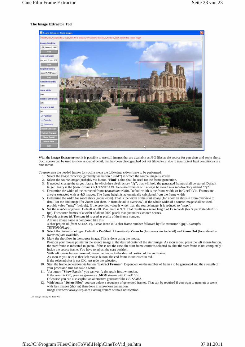
The Image Extractor Tool
With the Image Extractor tool it is possible to use still images that are available as JPG files as the source for pan shots and zoom shots. Such scenes can be used to show a special detail, that has been photographed bot not filmed (e.g. due to insufficient light conditions) in a cine movie.
To genereate the needed frames for such a scene the following actions have to be performed: 1. Select the image directory (probably via button "Find" ) in which the source image is stored. 2. Select the source image (probably via button "Find" ), that shall be used for the frame generation. 3. If needed, change the target library, in which the sub-directory "/g" , that will hold the generated frames shall be stored. Default
target library is the (Base Frame Dir) of S9ToAVI. Generated frames will always be stored in a sub-directory named "/g" . 4. Determine the width of the extracted frame (extraction width). Default width is the frame width set in CineToVid. Frames are
always extracted with as 4:3 images. The frame height is automatically calculated from the frame width. 5. Determine the width for zoom shots (zoom width). That is the width of the start image [for Zoom In shots -> from overview to
detail] or the end image [for Zoom Out shots -> from detail to overview]. If the whole width of a source image shall be used, provide valeu "max" (default). If the provided value is wider than the source image, it is reduced to "max" .
6. Set the number of frames. Default is 270. Maximum is 999. That results in a scene length of 15 seconds (for Super 8 standard 18 fps). For source frames of a widht of about 2000 pixels that guarantees smooth scenes.
7. Provide a Scene Id. The scne id is used as prefix of the frame numger. A frame image name is composed like this: 4 char project id (from S8ToAIV), 3 char scene id, 3 char frame number followed by file extension ".jpg". Example: TEST001001.jpg.
8. Select the desired shot type. Default is PanShot. Alternatively Zoom In (fom overview to detail) and Zoom Out (form detail to overview) are available.
9. Mark the shot flow in the source image. This is done using the mouse. Position your mouse pointer in the source image at the desired center of the start image. As soon as you press the left mouse button, the start frame is indicated in green. If this is not the case, the start frame center is selected so, that the start frame is not completely inside the source frame. You have to adjust the start position. With left mouse button presssed, move the mouse to the desired postion of the end frame. As soon as you release thee left mouse button, the end frame is indicated in red. If the selected shot is not OK, just redo the selection.
10. Start the frame generation via button "Extract Frames" . Dependent on the number of frames to be generated and the strength of your processor, this can take a while.
11. Via button "Show Result" you can verify the result in slow motion. If the result is OK, you can generate a .MOV stream with CineToVid. Of course you can also exploit an alternative generator like z.B. SSMM.
12. With button "Delete Files" you can delete a sequence of generated frames. That can be required if you want to generate a scene with less images (shorter) than done in a previous generation. Image Extractor always replaces existing frames without notification.
Last change: January 06. 2011 WK
Seite 23 von 23Cine Film Frame Extractor
07.01.2011file://C:\Program Files\CineToVid\Help\CineToVid_en.htm