CIE 13.3-1995 Method of Measuring and Specifying Colour ... · General Colour Rendering Index which...
21
CIE 13.3-1995 Method of Measuring and Specifying Colour Rendering Properties of Light Sources XIN Hongzheng
Transcript of CIE 13.3-1995 Method of Measuring and Specifying Colour ... · General Colour Rendering Index which...
CIE 13.3-1995Method of Measuring and Specifying Colour
Rendering Properties of Light Sources
XIN Hongzheng
It is recommended that the rating shall consist of a General Colour Rendering Index which may be supplemented by a set of Special Colour Rendering Indices.
The derivation of the Special Colour Rendering indices shall be based on a general comparison of the lengths of colour difference vectors in the 1964 Uniform Space.
5.7. General remarks
To apply the recommended Tesf-Colour Method the resultant colour shifts for suitably chosen testcolour samples must be calculated. For doing this, fisrstthe CIE 1931 tristimulus values of the various test-colours must be determined for both the illuminant to be tested and the reference illuminant. The next step is to transform these tristimulus values into co-ordinates of the 1960 UCS diagram.
The adaptive colour shift is accounted for by a VON KRIES transformation with the fundamental primaries given by JUOD . The difference between the chromaticities of the illuminant to be tested and the reference illuminant should be small enough to achieve a satisfactory approximation of the effect of chromatic adaptation.
Then the colour differences of the test-colour samples will be calculated in the 1964 Uniform Space.
5. RATING PROCEDURE
5.2. Reference Illuminant
The appraisal of colour rendering properties of a light source shall always be referred to a Reference lllurninanf, which may be defined mathematically. This reference illuminant shall be of the same or nearly the same chromaticity as the lamp to be tested.
Unless otherwise specified, the reference illuminant for light sources with correlate colour temperature below 5000 K shall be a Planckian radiator and from 5000 K one of a series of spectral power distributions of phases of daylight.
For special cases, CIE or other specific standard illurninants may serve as reference illuminant.
In all cases a full description in terms of spectral power distribution for wavelength intervals no greater than I0 nm over the visible spectrum shall be supplied for reference illurninants.
5.3. Tolerances for reference illuminant
The reference illuminant is intended to be of the same or nearly the same chromaticity as the lamp to be tested. It shall be selected so that the chromaticity difference DC is smaller than 5.4*10-3, if this is possible. This tolerance is suggested as a practical limit of difference.
The chromaticity difference DC between the lamp to be tested (uk, Vk) and the reference illuminant (Ur,Vr).
If the chromaticity difference between the lamp to be tested and the reference illuminant is greater than the tolerance of DC = 5.4*10-3 the resulting Colour Rendering Indices may be expected to become less accurate. In all cases the reference illuminant shall be indicated in brackets after the rating figure [e.g. Ra = 90(D65)].
5.4. Test-colour samples
A set of eight CIE-1974 test-colour samples (Ti, i= 1 ... 8y* is specified by the spectral radiance factors in Section 8, Table 1. These samples cover the hue circle, are moderate in saturation, and are approximately the same in lightness.
Data for further CIE-1974 test-colour samples (q,i= 9 ... 14)” representing a strong red, yellow, green and blue and representing complexion and foliage colours, are supplied. These samples vary widely in lightness and saturation.
For calculating Special Colour Rendering Indices recommended by this method data of any individual test-colour samples may be used (see section 6.2), whilst the calculation of the General Colour Rendehg Index is recommended to be based on data of the first eight CIE-1974 testcolour samples only (see section 6.3.).
In cases where spectral radiance factors are required af smaller steps than given in Section 8,Tables 1 and 2, linear inteqolation sbould be used.
5.5. Determination of CIE 7931 tnsfimulus values of the fest-colour samples
From a suitably accurate spectroradiometric measurement (see section 7.2 and 7.3) of the lamp to be tested combined with the spectral radiance factor data of the CIE - 1974 test-colour samples as given in Table 1 and 2, CIE 1931 tristimulus values X, Y, Z, CIE 1931 chromaticity co-ordinates x, y of test samples and the light sources resp. shall be determined. All chromaticitieswhether calculated or measured shall be given to four decimal places.
5.6. Transformation into 7960 UCS co-ordinates [I 7J
Colorimetric data must now be transformed from the CIE 1931 values ( X, V, Z, x ,y) to the (u,v) co-ordinate of the 1960 diagram.
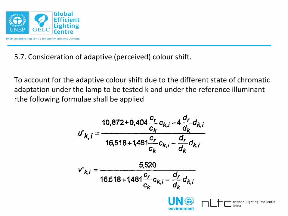
5.7. Consideration of adaptive (perceived) colour shift.
To account for the adaptive colour shift due to the different state of chromatic adaptation under the lamp to be tested k and under the reference illuminant rthe following formulae shall be applied
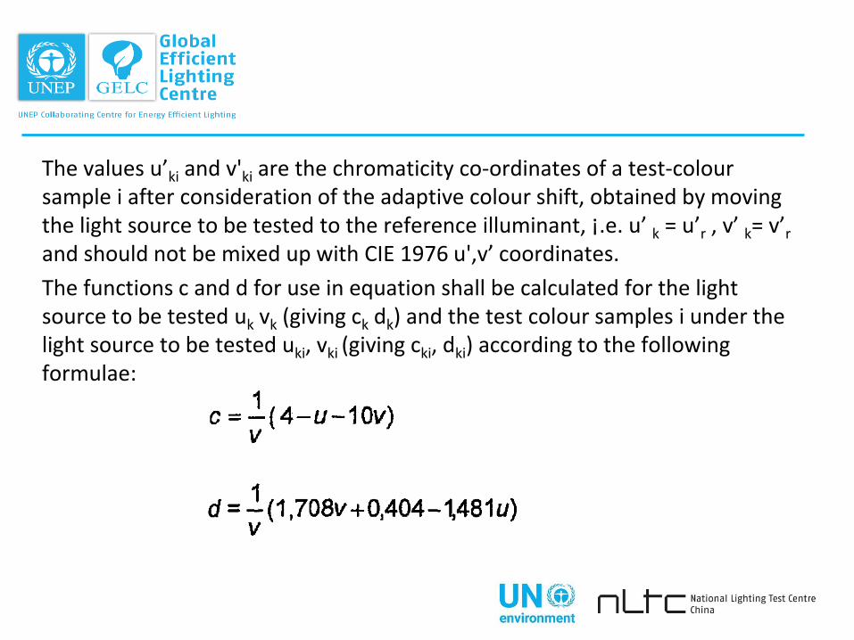
The values u’ki and v'ki are the chromaticity co-ordinates of a test-coloursample i after consideration of the adaptive colour shift, obtained by moving the light source to be tested to the reference illuminant, ¡.e. u’ k = u’r , v’ k= v’r
and should not be mixed up with CIE 1976 u',v’ coordinates.
The functions c and d for use in equation shall be calculated for the light source to be tested uk vk (giving ck dk) and the test colour samples i under the light source to be tested uki, vki (giving cki, dki) according to the following formulae:
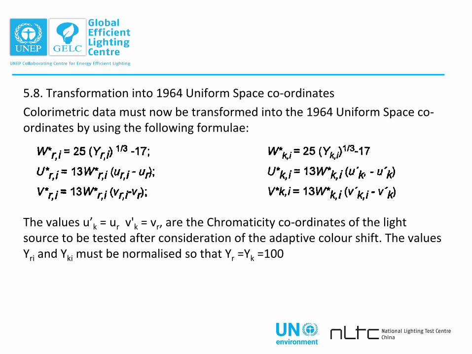
5.8. Transformation into 1964 Uniform Space co-ordinates
Colorimetric data must now be transformed into the 1964 Uniform Space co-ordinates by using the following formulae:
The values u’k = ur v'k = vr, are the Chromaticity co-ordinates of the light source to be tested after consideration of the adaptive colour shift. The values Yri and Yki must be normalised so that Yr =Yk =100
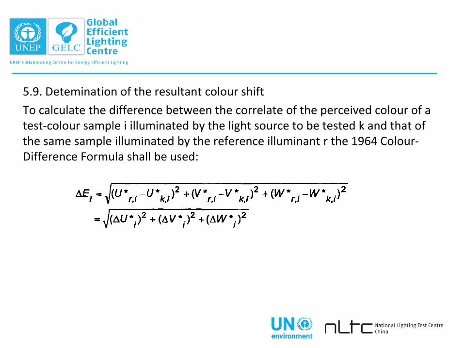
5.9. Detemination of the resultant colour shift
To calculate the difference between the correlate of the perceived colour of a test-colour sample i illuminated by the light source to be tested k and that of the same sample illuminated by the reference illuminant r the 1964 Colour-Difference Formula shall be used:
6. CALCULATION OF COLOUR RENDERING INDICES
6.1 Designation of CoIour Rendering Index
The Colour Rendering Index is designated by the letter R. The "Special Colourrendering Indices“ derived in accordance with clause 6.2 are designated by the symbol Ri (i = 1,2, 3 ... corresponding to the number of any individual test-colour sample that may be studied). The General Colour Rendering Index derived in accordance with 6.3 is designated by the symbol Ra.
6.2. Calculation of Special Colour Rendering Indices
The Special Colour Rendering Index Ri, based on DEi obtained for any individual test-colour sample, is to be derived by use of the following formula:
Ri= 100 – 4.6 DEi
rounding the result to the nearest whole number.
In case of figure 5 being in the first decimal place with subsequent zeros on the following places, the result should be rounded off or down to the next even number.
The index has been scaled so that I00 represents identity of colour co-ordinates of a test-colour sample under the source to be tested and its reference standard, and a General Colour Rendering Index of about 50 is assigned to a standard warn white fluorescent lamp used in earlier studies
tested against an incandescent lamp as reference. This scale adjustment is achieved by use of the factor 4.6 in the equation.
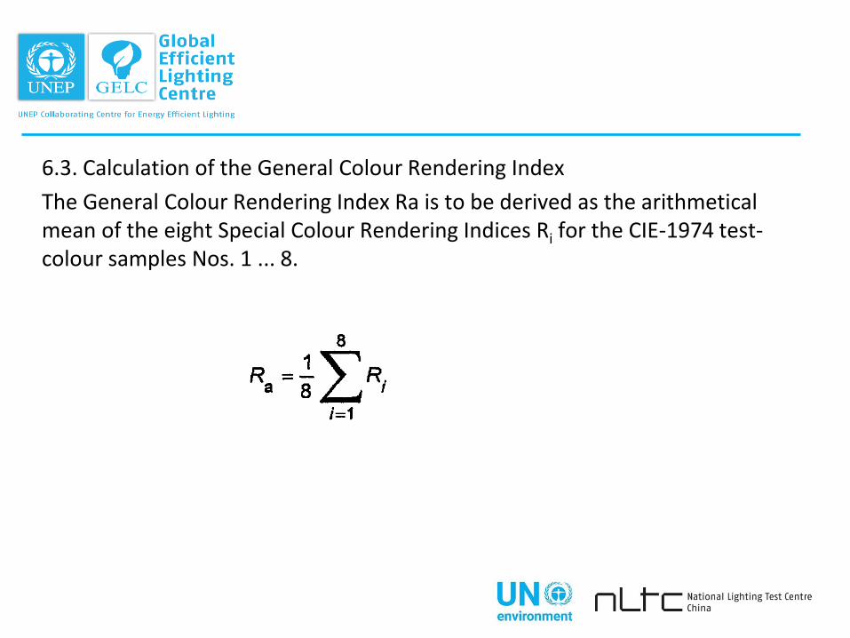
6.3. Calculation of the General Colour Rendering Index
The General Colour Rendering Index Ra is to be derived as the arithmetical mean of the eight Special Colour Rendering Indices Ri for the CIE-1974 test-colour samples Nos. 1 ... 8.
7. EXPLANATORY COMMENTS
7.1. Meaning of the Colour Rendering Indices
7.2 Uncertainties in the defemination of R
7.3. Influence of test conditions
7.4. Just perceptible differences in term of R
7.5. Interchangeability of lamps with regad to their colour rendering properties
8. TABLES
Table 1 : Spectral radiance factor of CIE-1974 test-colour samples Nos. 1 ... 8 to be used in calculating the General Colour Rendering Index.
Table 2: Spectral radiance factor of CIE -1974 test-colour samples Nos. 9...14


The Climate Technology Centre and Network (CTCN) fosters technology transfer and deployment at the request of developing countries through three core services: technical assistance, capacity building and scaling up international collaboration. The Centre is the operational arm of the UNFCCC Technology Mechanism, it is hosted and managed by the United Nations Environment and the United Nations Industrial Development Organization (UNIDO), and supported by more than 300 network partners around the world.
CTCN contact details:
Climate Technology Centre and NetworkUN City, Marmorvej 51DK-2100 Copenhagen, Denmark+45 4533 [email protected]
© 2017 GELC


![[XLS] · Web view6117 4 4.3 6120 4 4.3 6125 13 13.3 6130 13 13.3 6135 13 13.3 6140 13 13.3 6145 13 13.3 6150 13 13.3 6160 13 13.3 6210 4 4.3 6220 13 13.3 6230 4 4.3 6240 4 4.3 6250](https://static.fdocuments.us/doc/165x107/5b2a094f7f8b9a251e8b792d/xls-web-view6117-4-43-6120-4-43-6125-13-133-6130-13-133-6135-13-133-6140.jpg)