CIC Managed IP Phones Administrator's Guide · Complete the Provisioning Process (Multiple Managed...
124
! ! " # $ % ! " % & ’ ! " ! ( # # $ ( ) ’ " ( ! ! " ! * ! ! ( ! " " ( # $ + ! " ( ! " ! " ( & # ( ’ & , ( ’ - & ( " . ’ / / / - + ( / / / / + / 0 0 + 0
Transcript of CIC Managed IP Phones Administrator's Guide · Complete the Provisioning Process (Multiple Managed...

PureConnect®
2020 R1
Generated:
08-May-2020
Content last updated:
29-April-2020
See Change Log for summary ofchanges.
CIC Managed IP Phones
Administrator's Guide
Abstract
CIC systems can reduce initial IP phone configuration time and ongoingmaintenance with "managed IP phones". A provisioning subsystemmanages all IP phone configuration in Interaction Administrator, updatesmanufacturer-specific firmware, and manages resetting phones asneeded. This document describes all aspects of Polycom phone,Interaction SIP Station I & II, SIP Soft Phone, and AudioCodes phoneimplementation including configuring the network for managed IPphones, creating multiple managed IP phones and associated SIPstations, advanced configuration, boot and provision sequences, andtroubleshooting.
For the latest version of this document, see the PureConnectDocumentation Library at: http://help.genesys.com/cic.
For copyright and trademark information, seehttps://help.genesys.com/cic/desktop/copyright_and_trademark_information.htm.
1

2567777777889
11111111111212121313131415151517171818303139404444495353566066676767676775757575828283848484848585
Table of ContentsTable of ContentsCIC 2.4/3.0 to 2015 R1 or Later MigrationsCIC Provisioning SubsystemSupported Managed IP Phones
About Polycom PhonesSupported models and firmwareNew installations
About Interaction SIP Station I and II PhonesSupported models and firmwarePhysical descriptionNew installationsSIP compliancy statementsSIP Station I and II phone specifications
About SIP Soft PhonesNew installations
About AudioCodes and Genesys PhonesSupported AudioCodes and Genesys models and firmwareNew installations
Managed IP Phone Network ProvisioningStandard procedure: Automated provisioningManual provisioning (managed IP phones)
Managed IP Phone Creation MethodsCreate individual managed IP phonesUse Managed IP Phone Assistant to create multiple managed IP phones
Managed IP Phones and SIP SecurityBasic Managed IP Phones Configuration
IP Phone Network RequirementsIP Phone Network ArchitectureIP Phone Network Configuration Task ListConfigure the Network for Managed IP Phones
Use the SIP Soft Phone on the Voice VLANDNS ConfigurationEnable the TFTP Server on the CIC ServerCreate DHCP Provisioning RecordsConfigure the Time ServerImplement QoS in Your Environment
Individual Managed IP Phones for Test PurposesCreate Individual Managed IP Phones for Test PurposesRegistration Groups
Create Multiple Managed IP Phones Procedure SummaryCreate Managed IP Phone TemplatesCreate CSV Managed IP Phone ListsCreate Managed IP Phones with Managed IP Phone AssistantComplete the Provisioning Process (Multiple Managed IP Phones)
Polycom AdministrationCreate Managed IP Phones from Existing (Polycom) SIP Stations
Add the SIP Phone Information Update server parameterUpdate a common .cfg file to include sec.tagSerialNo="1" configuration parameterCreate managed IP phones from existing SIP stations using Managed IP Phone AssistantComplete the provisioning processManual provisioning
Polycom Firmware and PhonesPolycom Firmware for Supported and EOL PhonesPolycom Firmware Update RequiredSelectable Polycom FirmwareSpectraLink Wi-Fi Phone ConsiderationsSupport for End of Life DevicesPolycom Provisioning FTP Adapter
Managed IP Phone (Polycom) Configuration OptionsOptions tabAdvanced Options
Other Managed IP Phone (Polycom) Features2

8585878889898989909091919292939494949495959596969697979798999999
100100100101101101102102103103104105105107108108109110110110110110111111113113113113114114115115
Call parking / Zone pagingShared line appearancesCustom configuration files (Polycom)Supported languages for Polycom phonesExternal registrations (Polycom)Phone Simulator
Troubleshooting (Polycom)Polycom Phone is set to use TLS but can't receive callsPolycom phone cannot locate boot serverPolycom phone contacts boot server but cannot register
Boot and Provision Sequences (Polycom)Polycom boot sequenceProvision sequencePrecedence examplePhone simulator
Interaction SIP Station I and II AdministrationSet Up Interaction SIP Station I and II Phones
Unpack the package contentsFasten the phone to the desk (optional-Interaction SIP Station I only)Connect the network cable
Interaction SIP Station I and II Firmware for Supported PhonesFirmware for supported phones
Managed IP Phone (Interaction SIP Station I and II) Configuration OptionsOptions tab (SIP Station I and II)Advanced Options (Interaction SIP Station I and II)
Other Managed IP Phone (Interaction SIP Station I and II) FeaturesConfigurable speed dials (Interaction Station 1 only)LED status lightPhone Simulator
Troubleshooting (Interaction SIP Station I and II)Cannot hear audio through headsetInteraction SIP Station cannot start or connect to the network
Boot and Provision Sequences (Interaction SIP Station I and II)Firmware boot/provisioning sequencePhone simulator
SIP Soft Phone AdministrationSIP Soft Phone RequirementsSIP Soft Phone InstallationSIP Soft Phone Audio Device RequirementSIP Soft Phone Setup ProcessSIP Soft Phone Network Adapter Configuration and Auto-detection
Auto-detection of changes to the network adapterSIP Soft Phone Audio ConfigurationSet the User Interface Language for SIP Soft PhoneSIP Soft Phone Provisioning WizardSIP Soft Phone HelpManaged IP Phone (SIP Soft Phone) Configuration Options
Options tabSIP Soft Phone and Remote SurvivabilityTroubleshooting (SIP Soft Phone)
SIP Soft Phone cannot obtain configuration from provisioning serverSIP Soft Phone contacts provisioning server but cannot register
Startup and Provision Sequences (SIP Soft Phone)Startup sequence
Provision sequencePhone simulator
AudioCodes and Genesys Phone AdministrationAudioCodes and Genesys Firmware for Supported Phones
Firmware for supported phonesManaged IP Phone (AudioCodes and Genesys Phones) Configuration Options
Options tabAdvanced options
Other Managed IP Phone (AudioCodes and Genesys Phone) FeaturesDownload files
3

115115116116116117117117117118118118118119119119121
Boot and Provision Sequences (AudioCodes and Genesys Phones)Firmware boot/provisioning sequenceCustom configuration filesPhone simulator
AudioCodes DocumentationAppendixes
Appendix A: Non-standard Provisioning ScenariosRemote phonesConfigure a Polycom phone's boot server manuallyConfigure an Interaction SIP Station through the web interface
Appendix B: How Registrations Work (Proxy Settings)Registrations overviewRegistration typesSwitchover (failover)Remote survivability (fallback)External registrations (proxy settings)
Change Log
4

CIC 2.4/3.0 to 2015 R1 or Later MigrationsThe CIC 2.4/3.0 to CIC 2015 R1 or later migration package contains the tools and documentation to guide you through the processof migrating existing CIC 2.4/3.0 systems to CIC 2015 R1 or later. To download the latest versions of the migration tools anddocumentation, see the PureConnect Product Downloads page.
The CIC Migration Guide, included with the migration package, includes the procedures for migrating CIC 3.0 managed IP phonesfrom a CIC 3.0 system to a CIC 2015 R1 or later system. For more information, see the CIC Migration Guide.
5

CIC Provisioning SubsystemThe CIC provisioning subsystem on the CIC server manages the configuration of Polycom phones, Interaction SIP Station I and IIphones, SIP Soft Phones, AudioCodes phones, and Genesys phones for the purpose of reducing initial IP phone configuration timeand ongoing maintenance. The CIC provisioning subsystem manages the CIC features available on each phone, and also updatesthe firmware and manages resetting the phones as needed.
The Managed IP Phones container in Interaction Administrator contains all Polycom phones, Interaction SIP Station phones, SIPSoft Phones, AudioCodes phones, and Genesys phones that the CIC provisioning subsystem manages. The Managed IP Phonescontainer also contains templates to create managed IP phones and the SIP stations associated to each, and registration groupsfor organizing phones according to the sources of registration data.
The CIC provisioning subsystem allows administrators to complete the following tasks in Interaction Administrator:Set Polycom, Interaction SIP Station I and II, SIP Soft Phone, AudioCodes, and Genesys model templates with feature sets.Create individual managed Polycom phones, Interaction SIP Station I and II phone, SIP Soft phones, AudioCodes phones, andGenesys phones.Create multiple managed IP phones for Polycom phones; Interaction SIP Station I and II phones; SIP Soft Phones; AudioCodesphones; and Genesys phones from CSV files, and migrate existing Polycom phones to managed IP phones.Alter feature sets on Polycom, Interaction SIP Station I and II, SIP Soft Phones, AudioCodes phones, and Genesys phones. Onthe next reboot, the phones pull the updated configuration files automatically.Schedule an after hours reboot for one or multiple Polycom phones, Interaction SIP Station phones I and II, SIP Soft Phones,AudioCodes phones, and Genesys phones.Manage and distribute appropriate firmware versions to Polycom phones, Interaction SIP Station I and II Phones, AudioCodesphones, and Genesys phones.
6

Supported Managed IP Phones
About Polycom PhonesManaged IP phones support Polycom phones in new installations and migrations.
For the latest supported Polycom phone models and firmware, see Polycom Firmware for Supported and EOL Phones.
For the latest Polycom phone models and firmware that Genesys tested, see the Testlab site.
Genesys recommends that you create managed IP phones for Polycom phones using a CSV list as part of your new CIC installationto manage those phones more easily and efficiently. For more information, see Create Multiple Managed IP Phones ProcedureSummary.
Note:Non-managed Polycom phones are also supported in CIC 2015 R1 or later. However, you won't gain any of the advantages thatmanaged Polycom phones offer.
About Interaction SIP Station I and II PhonesManaged IP phones support Interactive SIP Station I and II phones in new installations. The Interaction SIP Station I and II are SIP-based devices designed for the contact center and enterprise environment that use power over Ethernet with physical controls forvolume, mute, on-hook/off-hook, and emergency/urgent speed autodial.
The Interaction SIP Station I and II offer a low-cost alternative to basic IP phones, soft phones with USB headsets, and high-pricedhigh-end multimedia phone devices.
For contact center and enterprise users, Interaction SIP Station I and II with Interaction Desktop and other CIC clients offer full-featured call control.
The major differences between Interaction SIP Station I and II are:Interaction SIP Station I, formerly "Interaction SIP Station", has Fast Ethernet ports, an emergency speed dial button, andrequires Power over Ethernet.Interaction SIP Station II, available in CIC 2015 R2 or later, has Gigabit Ethernet ports, a full dialpad, and the option of using apower adapter or Power over Ethernet.
Interaction SIP Station I and II work with the CIC provisioning subsystem and you configure them in Interaction Administrator in thesame way as Polycom phones, SIP Soft Phones, AudioCodes phones, and Genesys phones. You must implement each InteractionSIP Station I and II phone as a managed IP phone.
For the latest Interaction SIP Station I and II phone models and firmware that Genesys supports, see Interaction SIP Station I and IIFirmware for Supported Phones.
For the latest Interaction SIP Station I and II phone models and firmware that Genesys tested, see the Testlab site.
To manage incoming and outgoing calls, the Interaction SIP Station includes call control buttons and an LED status indicator.
Interaction SIP Station I
Supported models and firmware
New installations
Supported models and firmware
Physical description
7

4.5" (11.43 cm) x 4.5" (11.43cm) c 1.5" (3.81cm)
Interaction SIP Station II
4.5" (11.43 cm) x 4.7" (11.93cm) c 1.5" (3.81cm)
For more information, see:Interaction SIP Station and Interaction SIP Station II Product Information SheetInteraction SIP Station Quick ReferenceInteraction SIP Station II Quick Reference
Genesys recommends that you create managed IP phones for Interaction SIP Station I and II phones using a CSV list as part of yournew CIC installation to more easily and efficiently manage those phones. For more information, see Create Multiple Managed IPPhones Procedure Summary.
Interaction SIP Station I and II are fully compliant with the SIP communications standard and work in most global deployments,including EU countries.
The use of this equipment is subject to local rules and regulations. The following rules and regulations are relevant in some or allareas:
Federal Communications (FCC Statement)CE Notice (European Union)WEEE EU Directive
Federal Communications (FCC statement)
This device complies with FCC Rules Part 15. Operation is subject to the following two conditions: (1) this device cannot causeharmful interference and (2) this device must accept any interference received, including interference that can cause undesirableoperation.
This test equipment complies within the limit of a Class A digital device, pursuant to Part 15 of the FCC Rules. These limits providereasonable protection against harmful interference in a residential installation.
New installations
SIP compliancy statements
8

However, there is no guarantee that interference won't occur in a particular installation. If this equipment does cause harmfulinterference to radio or television reception, which you can determine by switching the equipment on and off, the user can try tocorrect the interference using one or more of the following measures:1. Reorient or relocate the interference receiving antenna.2. Increase the distance of separation between the equipment and interference receiver.3. Connect the equipment to a power outlet on a circuit different from that to which the interference receiver connects.4. Consult the dealer or an experienced radio/TV technician for assistance.5. Changes or modifications that the party responsible for compliance doesn't expressly approve can void the user's authority to
operate the equipment.
CE Notice (European Union)
The symbol indicates compliance of this equipment to the EMC Directive and the Low Voltage Directive of the European Union.These markings indicate that this system meets the following technical standards:1. EN 55022 - Limits and Methods of Measurement of Radio Interference Characteristics of Information Technology Equipment
Note:EN 55022 emissions requirements provide for two classifications:
Class A is for typical commercial areas.Class B is for typical domestic areas.
2. EN 55024 - Information technology equipment - Immunity characteristics - Limits and methods of measurement3. EN 61000-3-2 - Electromagnetic compatibility (EMC) - Part 3: Limits - Section 2: Limits for harmonic current emissions
(Equipment input current up to and including 16 A per phase)4. EN 61000-3-3 - Electromagnetic compatibility (EMC) - Part 3: Limits - Section 3: Limitation of voltage fluctuations and flicker in
low-voltage supply systems for equipment with rated current up to and including 16 A.5. EN 60950 - Safety of Information Technology Equipment.
To determine which classification applies to your device, examine the FCC registration label on the device. If the label indicatesa Class A rating, the following warning applies to your computer:This device is classified for use in a typical Class B domestic environment.
WEEE EU Directive
Pursuant to the WEEE EU Directive, don't dispose of electronic and electrical waste with unsorted waste. For disposal of thisproduct, contact your local recycling authority.
The following table summarizes Interaction SIP Station I and II phone specifications.
Feature Details
VoIP Signaling Protocols SIP: RFC 3261, RFC 2327 (SDP)
Data Protocols IPv4, TCP, UDP, ICMP, ARP, DNS
802.1p/Q for Traffic Priority and QoS
ToS (Type of Service) field, indicating desired QoS
DHCP Client
NTP Client
SIP Station I and II phone specifications
9

Media Processing Voice Coders: G.711, G.723.1, G.729A/B, G.722. Additionally, Interaction SIP Station II supportsOpus.
Acoustic Echo Cancelation: G.168-2004 compliant, 64-msec tail length
Adaptive Jitter Buffer 300 ms
Voice Activity Detection
Comfort Noise Generation
Packet Lost Concealment
RTP/RTCP Packetization (RFC 3550, RFC 3551)
DTMF Relay (RFC 2833)
Telephony Features Speed Dial (Interaction SIP Station I) Dialpad (Interaction SIP Station II), pickup, disconnect,switchover/failover support
Configuration/Management Automatic provisioning for firmware and configuration file upgrade
DHCP options for automatic provisioning
Port Usage Default port 4000 for RTP traffic, port 4001 for RTCP traffic. Depends on the value of Media PortStart Range in the Managed IP Phone Configuration Options in Interaction Administrator.
Power Class 1 PoE
Optional DC to USB power cord (Interaction SIP Station II only)
Hardware Connectors interfaces:
2 x RJ-45 ports (10/100BaseT Ethernet) for WAN and LAN (Gigabit support on Interaction SIP Station II)
PoE: IEEE802.3af
RJ-9 port (jack) for Handset
Mounting:
Wall mounting
Power:
Class 1 PoE
Keys:
Emergency Speed Dial (Interaction SIP Station I)
Dialpad (Interaction SIP Station II)
Pickup Disconnect
Mute
Volume Up
Volume Down
Multi-function status LED
Idle
Call alerting
On mute
Volume up/down
10

About SIP Soft PhonesPureConnect's SIP Soft Phone is a standalone application that places and controls calls, providing SIP endpoint functionality. TheSIP Soft Phone application requires a USB headset to deliver audio to the user. You can use the SIP Soft Phone with InteractionDesktop and other CIC clients.
The SIP Soft Phone application works with the CIC provisioning subsystem and you configure it in Interaction Administrator in thesame way as Polycom phones, Interaction SIP Station phones, AudioCodes phones, and Genesys phones. You must implementeach SIP Soft Phone as a managed IP phone.
Create a managed IP phone for each SIP Soft Phone as part of your new CIC installation using a comma-separated values (CSV)list. For more information, see Create Multiple Managed IP Phones Procedure Summary.
About AudioCodes and Genesys Phones
For the latest AudioCodes and Genesys phones models and firmware that Genesys supports, see AudioCodes and GenesysFirmware for Supported Phones.
For the latest AudioCodes and Genesys phone models and firmware that Genesys tested, see the Testlab site.
For more information about the AudioCodes and Genesys phones, see the AudioCodes website.
Genesys recommends that you create managed IP phones for AudioCodes and Genesys phones using a comma-separated values(CSV) list as part of your new CIC installation to manage those phones more easily and efficiently. For more information, seeCreate Multiple Managed IP Phones Procedure Summary.
New installations
Supported AudioCodes and Genesys models and firmware
New installations
11

Managed IP Phone Network Provisioning
Standard procedure: Automated provisioningCIC provisioning of managed IP phones connects the managed IP phones and downloads their configurations from the CIC server.The goal for CIC Managed IP Phone provisioning is to automate it as much as possible so that it doesn't need user participation.
The two factors necessary to the success of automated provisioning are:Use a DHCP server (and DNS server for a Switchover pair)The administrator sets the appropriate DHCP server records to configure the managed Polycom, Interaction SIP Station I and II,SIP Soft Phone, AudioCodes, and Genesys network. If the CIC system uses a Switchover pair, the administrator must also settwo types of DNS records so that the phones switch to the active CIC server automatically when a Switchover event occurs.For more information, see Create DNS Host (A) Records for Switchover.Provide the MAC Address (Polycom, Interaction SIP Station I and II, AudioCodes, and Genesys) or the Full Computer Name (SIPSoft Phone) for each managed IP phoneFor an initial, new managed IP phone deployment, the administrator provides the MAC Addresses for Polycom phones,Interaction SIP Station I and II phones, AudioCodes phones, and Genesys phones, and the Full Computer Names for SIP SoftPhones in a CSV list that imports to Interaction Administrator. (For more information, see Create Multiple Managed IP PhonesProcedure Summary.) When a managed IP phone contacts the provisioning subsystem to request configuration, theprovisioning subsystem matches the phone’s MAC address or computer name with an existing managed IP phoneconfiguration, and it serves the configuration to the device without any additional steps.
Manual provisioning (managed IP phones)Manual provisioning of some or all managed IP phones are necessary in certain circumstances, for example:
You didn't specify the MAC address or full computer name in Interaction Administrator configuration for some or all Polycom,Interaction SIP Station I and II, and/or SIP Soft Phones, AudioCodes phones, or Genesys phones.
Note:In an implementation of new Polycom, Interaction SIP Station I and II, SIP Soft Phones, AudioCodes phones, and/orGenesys phones, the MAC address or full computer name may not be known at the same time the comma-separated values(CSV) list is created.
The CIC system has no DHCP server or it cannot access the DHCP server.Some Polycom phones, Interaction SIP Station I and II phones, SIP Soft Phones, AudioCodes phones, and/or Genesys phonesare in remote locations.
Typically, an administrator with required permissions does the manual provisioning through the phone’s local user interface. Insome cases (for example, remote locations), users must do the manual provisioning. You do manual provisioning on each managedphone's configuration.
For more information, see Complete the Provisioning Process (Multiple Managed IP Phones).
12

Managed IP Phone Creation Methods
Create individual managed IP phonesGenesys recommends that you create one or more managed IP phones individually in the Interaction Administrator Managed IPPhones container under the following circumstances only:
For test purposesFor more information, see Create Individual Managed IP Phones for Test Purposes. Walk through the creation of an individualmanaged IP phone so that you can explore the Managed IP Phone container and learn about managed IP phone configurationbefore deploying multiple managed IP phones in new or upgrade installations.Post-implementationCreate managed IP phones individually after the initial managed IP phone implementation as you add more managed IP phonesto the network.
Use Managed IP Phone Assistant to create multiple managed IP phonesThe standard procedure for the initial managed IP phone implementation for a CIC installation is to create new managed IP phones(Polycom, Interaction SIP Station I and II, SIP Soft Phone, AudioCodes, and Genesys) using Managed IP Phone Assistant inInteraction Administrator. Managed IP Phone Assistant is a wizard that simplifies the creation of multiple managed IP phones andassociated SIP stations.
To use the Managed IP Phone Assistant Import option to create multiple managed IP phones and associated SIP stations1. Create one or more managed IP phone templates.2. Create a CSV Managed IP Phone List based on 1) Template, or 2) Type, Manufacturer, and Model.3. Run the Managed IP Phone Assistant, choosing the Import option to import the CSV Managed IP Phone List.
For more information, see Create Multiple Managed IP Phones Procedure Summary.
13

Managed IP Phones and SIP SecurityPolycom, SIP Soft Phone, Interaction SIP Station I and II, AudioCodes phones, and Genesys phones support SIP line security(TLS/SRTP) for SIP station-to-station calls and managed IP phone registration groups. TLS/STRP support for AudioCodes phones,and Genesys phones is available in CIC 2016 R4 and later. TLS/STRP support for Interaction SIP Station I and II phones is notavailable.For more information about SIP security features and configuration, see:
PureConnect Security Features Technical Reference (requires logon credentials)Interaction Administrator Help
14

Basic Managed IP Phones Configuration
IP Phone Network RequirementsCIC Managed IP Phones support the following network protocols:
Domain Name System (DNS) protocol to specify a DNS domain for the voice VLAN, and for Switchover server pairs to resolveDNS names for the two servers so that phones switch to the active CIC server automatically when a Switchover event occurs.Dynamic Host Configuration Protocol (DHCP) to reduce system administration workload, allowing the addition of voice VLANdevices to the network with little or no manual configuration.
IP Phone Network ArchitectureThe CIC network architecture is built around the concept of VLANs. A VLAN (Virtual-LAN) is a network within a network which youaccess by tagging network traffic for that VLAN. Any network can have many VLANs and can allow for routing traffic between theVLANs as needed. VLANs serve as a way to isolate certain devices from the general network (typically called the data VLAN). Theyalso serve to isolate the traffic from those devices from general view, whether by devices not on that specific VLAN or by maliciousparties attempting to penetrate the network.
It is important to isolate all the voice traffic in a CIC system onto a separate VLAN, typically called the voice VLAN. This meansthat all devices that generate/pass on voice traffic need to exist on the voice VLAN. The devices includes the CIC Servers, phones,Media Servers, Gateways, and Interaction SIP Proxies.
Accessing CIC Servers, Media Servers, and Proxies from the data VLAN allows for easy remote access. Giving servers access toboth VLANs complicates configuration, though, as they must have multiple NICs (Network Interface Controllers) and properDNS/DHCP configuration on both VLANs. The configuration can become more complicated when including remote sites.
The following diagrams show the ideal configuration for the network over multiple offices, but your actual configuration can differ.For instance, although the Managed Proxy and Media Server for a remote office are shown as two distinct servers, in some cases itis appropriate to have them share the same physical device.
The following diagram shows a wide view of a typical network configuration for managed IP phones.
15

Each site, including the home office, needs access to the voice VLAN over the WAN, and each site needs its own DHCP and DNSservers. An exception is very small offices that can use the DNS and DHCP servers of the home office over the WAN. However, itincreases WAN traffic so, if possible, you should avoid. Also, any sites that have Interaction SIP Station I and II deployed must havea DHCP server on both the voice VLAN and the data VLAN.
The following diagrams show basic home office and remote office network architecture.
16
DNS and DHCP servers are separate, non-CIC Servers in the CIC system network. It allows for DHCP and DNS maintenance withoutputting the CIC server at risk. Use a static IP address for each of the non-phone devices (CIC server, Media Server, Proxy, Gateway)so that the system can contact them in the event of a reboot without the querying device needing to refresh its data.
For phones, use dynamic IP addresses that the DHCP server assigns to them for maintenance and configuration considerations.
IP Phone Network Configuration Task ListDetermine the IP phone network settings you need for your implementation ahead of time so that managed IP phone process canrun as smoothly as possible.
Note:Interaction SIP Station is abbreviated as ISS.
Task Polycom ISS I and II,AudioCodes, and Genesys
SIP Soft Phone
Create a DNS domain for the voice VLAN X X
Create DNS Host (A) records for Switchover X X X
Create DNS SRV records for Switchover X X X
Configure the TFTP server X
Create DHCP provisioning records X X X
Configure time server X X X
Implement QoS in your environment X X X
Configure the Network for Managed IP Phones
17

It is possible to use the SIP Soft Phone on a different VLAN (your voice VLAN). The support for this method is not within theapplication layer, so the SIP Soft Phone itself cannot accomplish this without help at lower layers. Third-party drivers for manyNetwork Interface Cards (NICs) allow the support for multiple VLANs through a single NIC port by creating virtual adapters. Whenadding each VLAN to the configuration, it creates a new virtual NIC, which looks like a second physical NIC to the OperatingSystem. The SIP Soft Phone configuration allows you to select which NIC to use for SIP and RTP. Selecting the virtual NIC thatcommunicates on the voice VLAN binds that data to that NIC, which the NIC drivers then assign to the voice VLAN. For moreinformation about whether your workstation's NIC supports this feature, consult the manufacturer.
Create a Voice DNS Forward Lookup Zone
Genesys recommends that you create a "voice" DNS forward lookup zone to create a separate DNS domain for the voice VLAN(managed IP phones and SIP lines) for the following phones:
PolycomInteraction SIP Station I and IIAudioCodesGenesys
For example, you can create a DNS domain for voice, yourvoicelan.voip, in addition to the existing DNS domain for data,yourdatalan.local or yourdatalan.com, and set each NIC to register with the appropriate DNS server. (The examples usedhere are lab.voip and lab.local) This action ensures that when the DHCP scope provides the managed IP phones with theprimary DNS lookup zone, the phones register correctly with the DNS voice domain.
You must be familiar with DNS server configuration and have required domain administrator permissions to complete the networkconfiguration procedures.
To create a voice DNS forward lookup zone1. On the computer that functions as the DNS server, click Start->Programs->Administrative Tools->DNS.2. Right-click on Forward Lookup Zones and then click New Zone…
The New Zone Wizard launches.
Use the SIP Soft Phone on the Voice VLAN
DNS Configuration
18

3. On the Zone Type page, click Primary Zone (default).
Leave Store the zone in Active directory selected (default).4. On the Active Directory Zone Replication Scope page, click To all DNS servers in the Active Directory domain (default).
19

5. On the Zone Name page, type the name to use for the DNS voice domain (in this example, lab.voip).
6. On the Dynamic Update page, click Do not allow dynamic updates.
20

For a more secure environment, the server "voice" NIC IP addresses need to register in the voice DNS domain only. Genesysdoesn't allow the server to register them dynamically.
7. Once the New Zone wizard completes, click Finish.
The new lab.voip forward lookup zone for the DNS voice domain is now available in the Forward Lookup Zones container.
21

8. Complete the steps to Create DNS Host (A) Records for Servers in the DNS Voice Domain.
Create DNS Host (A) Records for Servers in the DNS Voice Domain
Create a DNS Host (A) record for each server in the DNS voice domain (for example, CIC server(s), media server, proxy server). Thisprocedure is necessary because Genesys is administering the DNS records manually instead of allowing dynamic registrations. Youmust be familiar with DNS server configuration and have required domain administrator permissions to complete the networkconfiguration procedures.
To create a DNS Host (A) record1. Right-click on the new DNS Forward Lookup zone for voice (in this example, lab.voip) and then click New Host (A or AAAA)
2. In New Host dialog box, complete the following information.
22
Name: Name of a server in the DNS voice domain (in this example, the CIC server vm40ic1).IP address: IP address of this server (in this example, 10.250.1.151). You can verify the IP address value for the selectedserver on the voice VLAN by typing ipconfig in the command-line on the server.Create associated pointer (PTR) record: If selected, the system creates an associated pointer record for the new host. Ensurethat you select this check box.
3. Click Add Host. A message appears, indicating that the host record (in this example, vm40ic1.lab.voip) createdsuccessfully.
4. Click OK.5. Repeat the previous steps to create records for the second CIC server, Proxy Server, Media Server and other servers to include
in the DNS voice domain. When finished, the records you created are available in the voice VLAN forward look up zone (in thisexample, lab.voip) container.
Create DNS Host (A) Records for Switchover
If your implementation includes a Switchover pair, complete this procedure for the following phones:PolycomInteraction SIP Station 1 and II
23

AudiocodesGenesys
This procedure creates the DNS Host (A) records required for provisioning for the two CIC servers so that the phones can find theactive server when booting up (provisioning) and completing SIP operations. You must be familiar with DNS server configurationand have required domain administrator permissions to complete the network configuration procedures.
Create two "provisioning" DNS Host (A) records for the Switchover pair with the same name, then use the different CIC server voiceVLAN IP addresses, as shown in the following table containing sample entries.
Host (A) record name Type Address
provision.lab.voip A 10.250.1.151
provision.lab.voip A 10.250.1.152
Note:Genesys recommends that you use "provision" in the Host (A) record name to identify clearly the purpose of these records.The Host (A) record name cannot match any existing record name.Do not use the name of either CIC server.
To create the DNS Host (A) records for the Switchover pair1. Right-click on the new DNS forward lookup zone for voice (in this example, lab.voip) and then click New Host (A or AAA)…2. In the New Host dialog box, complete the following information.
Name: Name of the provisioning Host (A) record for the Switchover pair (in this example, provision).IP address: IP address of the active CIC server (in this example, 10.250.1.151).Create associated pointer (PTR) record: If selected, the system doesn't create an associated pointer record for the new host.Ensure that you clear this check box.
3. Click OK. A message appears, indicating that the host record (in this example, provision.lab.voip) created successfully.4. Repeat the first two steps to create the second Host (A) record and then do the following:
a. In the Name box, type the exact same name that you used for the provisioning Host (A) (in this example, provision).b. In the IP address field, specify the IP address of the backup CIC server (in this example, 10.250.1.152).c. All other fields should be identical to the first Host (A) record created.
When finished, the records that you created in the voice VLAN forward look up zone (in this example, lab.voip) appear in thecontainer.
24
5. To verify the records that you created, run an nslookup on the command-line for this record, for example,provision.lab.voip. The server returns the IP addresses in a random order.
Create DNS Service Location (SRV) Records for Switchover
If your implementation includes a Switchover pair, complete the following procedures to create the DNS SRV records required forprovisioning for the two CIC servers so that the phones can find the active server when booting up (provisioning) and completingSIP operations.
You need to create a DNS SRV record for each of the supported SIP line transport protocols (UDP, TCP, and TLS over TCP (SIPSecure or _sips)) that you plan to use for the Switchover pair. For example, if you plan to use the TCP protocol, create two DNS SRVrecords for TCP, one for the active CIC server and one for the backup CIC server. You must be familiar with DNS serverconfiguration and have required domain administrator permissions to complete the network configuration procedures.
If you plan to use all three protocols, you need to create six DNS SRV records, as shown in the following table containing sampleentries:
25

Service Priority Weight Port Hostname
_sip._tcp 0 0 8060 vm40ic1.lab.voip
_sip._tcp 0 0 8060 vm40ic2.lab.voip
_sips._tcp 0 0 8061 vm40ic1.lab.voip
_sips._tcp 0 0 8061 vm40ic2.lab.voip
_sip._udp 0 0 8060 vm40ic1.lab.voip
_sip._udp 0 0 8060 vm40ic2.lab.voip
Note:Port configuration may vary. The ports specified in the table are the default port configurations in CIC that match thedefault registration group and SIP line configurations.Interaction SIP Station I supports DNS SRV in CIC 4.0 SU 4 to SU 6 and CIC 2015 R1 and later, which containsv.1.2.2._p10_build_17 or later firmware.Interaction SIP Station I and II support DNS SRV in CIC 2015 R2 and later which contains v.2.0.4.15.7 or later firmware.AudioCodes and Genesys phones support DNS SRV in CIC 4.0 SU 5 to SU 6 and CIC 2015 R1 and later, which containsv2.0.0.18 or later firmware.
To create the DNS SRV records1. Right-click on lab.voip to create two DNS domains for SRV (one for _tcp and one for _udp) and then click New Domain.
2. In the New DNS Domain dialog box, type _tcp.
3. Repeat steps 1 and 2 to create the _udp domain.4. Right-click on the new DNS forward lookup zone for voice (in this example, lab.voip) and then click Other New Records
26

5. In the Resource Record Type dialog box, click Service Location (SRV) and then click Create Record.
6. In the New Resource Record dialog box, complete the information for the first DNS SRV record for the active CIC server.
27

Service: Name of the service for this DNS SRV record (for example, _sip).Protocol: Protocol for this DNS SRV record (for example, _tcp). The container for the protocol will be created if it does notalready exist.Port number: Port number for this DNS SRV record (for example, 8060).Priority: Leave the default setting.Weight: Leave the default setting.Host offering this service: FQDN name of the active CIC server (for example, vm40ic1.lab.voip).
7. Repeat steps 4 through 6 to create the DNS SRV record for the same protocol for the backup CIC server. Ensure that all theboxes in the New Resource Record identical are identical to the first DNS SRV record except for Host offering this service. Usethe name of the backup server (in this example, vm40ic2.lab.voip).
8. Repeat steps 4 through 7 to create the rest of the DNS SRV records for the Switchover pair. Following is an example of the DNSSRV records created in the _tcp container for TCP and TLS over TCP.
9. To verify the records that you created in the _tcp container, run an nslookup on the command-line for this record, for example,_sip_tcp.lab.voip. The server returns the IP addresses in a random order.
28

Following is an example of the DNS SRV records created in the _udp container.
10. To verify the records that you created in the _udp container, do an nslookup on the command-line for this record, for example,_sip_udp.lab.voip. The server returns the IP addresses in a random order.
In Create Individual Managed IP Phones for Test Purposes, you configure the default Registration group to obtain registration29

settings from the DNS SRV records that you created.
Interaction SIP Station I and II, AudioCodes, and Genesys phones obtain firmware and configuration using HTTP instead of TFTP,allowing for a faster upgrade process. However, they still use the TFTP server when an error occurs during a firmware upgradeprocess (recovery mode). Therefore, all sites with Interaction SIP Station I and II, AudioCodes, and Genesys phones need to enablethe TFTP server on the CIC serverthe TFTP server.
You must enable the TFTP server on the IC Server to open up the TFTP server to accept TFTP requests, and then configure it to talkto the Provision server on the CIC server.
Note:If your implementation includes a Switchover pair, enable the TFTP server on only one of the servers in the Switchover pair. TheIP address of that server is the value used for DHCP Option 66.
To enable the TFTP server on the CIC server1. Click Start->Programs->PureConnect...IC Setup Assistant. The IC Setup Assistant page appears.
2. Click Options.3. On the Select IC Optional Components page, if not selected, select TFTP Server.
Enable the TFTP Server on the CIC Server
30

Note:If your implementation includes a Switchover pair, Switchover Service is selected also.
Create DHCP Provisioning Records
31

Managed IP Phones Administrator Guide
Required DHCP Option Provisioning Records
The following table describes the required DHCP server provisioning records configuration for each managed IP phone type. Fornotes about each managed IP phone type, see the following:
Polycom DHCP Record Notes Interaction SIP Station I and II, AudioCodes, and Genesys DHCP Record NotesSIP Soft Phone DHCP Record Notes
Note:ISS is the abbreviation for Interaction SIP Station.
Optionrecord
Purpose Example value Type Polycom ISS I and II,AudioCodes, andGenesys Phones
SIP SoftPhone
002 Time Offset FFFF.B9B0 (hexadecimal input value) -18000 (converted value)
Long X X
004 Time Server mytimeserver.lab.voip Array
X X
006 DNS Server 10.250.1.5
10.250.0.2
Array
X X X
015 DNS DomainName
lab.voip String
X X
042 NTP Server mytimeserver.lab.voip Array
X X
066 TFTP Server IPAddress
10.0.0.11 String
X
067 FirmwareFilename
sip100.img Interaction SIP Station Iand II
405.img AudioCodes 405, Genesys405
405hd.img AudioCodes 405HD,Genesys 405HD
420hd.img AudioCodes 420HD,Genesys 420HD
430hd.img AudioCodes 430HD,Genesys 430HD
440hd.img AudioCodes 440HD,Genesys 440HD
String
X
132 VLAN ID 100 String
X
160 Provisioning URL http://provision.lab.voip:8088 String
X X X
Copyright and trademark
32

Polycom DHCP Record Notes
Time server settings
Options 002, 004, and 042 configure the time server on the DHCP server. Alternatively, you can choose to configure the time serverin Interaction Administrator. For more information, see Configure the Time Server.
Option 002: The values for Option 002 require hexadecimal numbers. To convert values to hexadecimal numbers, see How toCalculate the Hexadecimal Value for DHCP Option 2 (time offset).Options 004 or 042: Set either option 004 or 042, not both. Genesys recommends setting multiple values in the Option 004 or042 record, particularly for CIC systems using TLS, to provide redundancy. If you do not specify values for one of these options,the provisioning server uses the default location and SNTP server settings provided in the phone configuration files, based onthe region of the phone.
Option 015
Use the DNS domain for the voice VLAN for the Option 015 record.
Option 160
Option 160 is the primary default record that Polycom phones use to find the provisioning server.Option 160 takes precedence over Option 066 (the secondary default record that Polycom phones use to find the provisioningserver). Genesys recommends that you do not use Option 066 for Polycom phones.Switchover environments: Ensure that you created the DNS Host (A) records as described in Create DNS Host (A) Records forSwitchover and DNS Service Location (SRV) records as described in Create DNS Service Location (SRV) Records forSwitchover. For DHCP Option 160, use the DNS Host (A) provisioning record in the URL.
33

Interaction SIP Station I and II, AudioCodes, and Genesys DHCP Record Notes
Time server settings
Options 002, 004, and 042 configure the time server on the DHCP server.Option 002: The values for Option 002 require hexadecimal numbers. To convert values to hexadecimal numbers, see How toCalculate the Hexadecimal Value for DHCP Option 2s(time offset).Options 004 or 042: Set either option 004 or 042, not both. If you do not specify values for one of these options, theprovisioning server uses the default location and SNTP server settings provided in the phone configuration files, based on theregion of the phone.
All DHCP Option records
Set all DHCP Options on the DHCP server in both the data and voice VLANs.
Option 066
Option 066 is the IP address of the TFTP server used in recovery mode.Ensure that you enabled and configured the TFTP server as described in Enable the TFTP Server on the CIC Server.Switchover environments: Ensure that you enabled and configured the TFTP server on the initial active server only, as describedin Enable the TFTP Server on the CIC Server. Set DHCP Option 066 on the initial active server only.
Option 067
Option 067 is for implementations using different managed IP phone types and models, requiring recovery mode. To handle theconflict, set up Option 067 according to Vendor Class. The value for Option 067 is one of the following:
sip100.img (Interaction SIP Station I firmware filename)sip200.img (Interaction SIP Station II firmware filename)405.img (AudioCodes 405 or Genesys 405 firmware filename)405hd.img (AudioCodes 405HD or Genesys 405HD firmware filename)420hd.img (AudioCodes 420HD or Genesys 420HD firmware filename).430hd.img (AudioCodes 430HD or Genesys 430HD firmware filename).440hd.img (AudioCodes 440HD or Genesys 440HD firmware filename).
See Configure DHCP Records for Multiple Phone Model Recovery.
Option 132
If your Interaction SIP Station I, Interaction SIP Station II, AudioCodes phones, or Genesys phones communicate on any VLANother than the native VLAN (use a voice VLAN), use Option 132. Interaction SIP Station I and II, AudioCodes, and Genesysphones have a special "recovery mode" that it falls back to under certain conditions, such as a firmware update failure. This fail-safe mode brings the device up in the native VLAN and ignores any CDP/LLDP VLAN assignment. Since CDP/LLDP is ignored,the only way to push the device to the voice VLAN is to set option 132 in the native VLAN DHCP scope. You do not need to setthis option in the voice VLAN DHCP scope. Failure to set this option causes any device that goes into "recovery mode" for anyreason to stay in that mode until it either finds provisioning information on native VLAN, or obtains an option 132 message inthe native VLAN DHCP assignment. Option 132 has no effect in normal (non-recovery) mode.
Note:2.0.4+ firmware caches the VLAN tag acquired from CDP/LLDP during normal operations. This caching negates the needfor Option 132 unless the phone factory reset or otherwise lost the cache. For this reason, configure Option 132 in thenative VLAN.
Option 160
Option 160 is the default record that Interaction SIP Station I and II, AudioCodes phones, and Genesys phones use to find theprovisioning server.Switchover environments: Ensure that you created the DNS Host (A) records as described in "Create DNS Host (A) records forSwitchover". For DHCP Option 160, use the DNS Host (A) provisioning record in the URL.
34
SIP Soft Phone DHCP Record Notes
Option 006
Option 006 is the default DHCP record used for DNS server discovery. Use the SIP Soft Phone with DNS to allow referencing the CICserver by name. You can also set up DNS discovery manually in the client workstation's network configuration.
Option 160
Option 160 is the default record that the SIP Soft Phone uses to find the provisioning server. It is the only DHCP record required forthe SIP Soft Phone.
Configure DHCP Option Records
Use this procedure to configure DHCP option records for each of the managed IP phone types. You must be familiar with DHCPserver configuration and have required domain administrator permissions to complete the network configuration procedures.
The following example creates DHCP Option 160.
To configure DHCP option records1. On the computer that functions as the DHCP server, click Start->Programs->Administrative Tools->DHCP, or use Server
Manager to open DHCP.2. Right-click the DHCP server (if using a Windows 2008 server, right-click IPv4) and then click Set Predefined Options
3. In the Predefined Options and Values dialog box, click Add.
35

4. In the Option Type dialog box, complete the information.
Name: Name for this record, related to IP phone provisioning.Data type: Data type (in this example, String).Code: Option record code (in this example, 160).Description: Description for this record, related to IP phone provisioning.
5. Click OK.6. In the Predefined Options and Values dialog box, in the String Value box, type the URL for the IP phones to use to contact the
provisioning server (for a Switchover pair, use the provisioning DNS Host (A) record).
7. Click OK.8. Right-click the Scope Options (or Server Options) container and then click Configure Options.
36

9. In the Scope Options dialog box, select the check box for the option record that you created (in this example, 160 IP PhoneProvisioning Server).
10. Repeat these steps to create the other DHCP option records required for the appropriate managed IP phone type.
Configure DHCP Records for Multiple Phone Model Recovery
Some environments use multiple models requiring recovery mode. For example, some environments use AudioCodes, Genesys,Interaction SIP Station I, and Interaction SIP Station II phones. Each requires a different Option 67 value. To handle the conflict,environments using multiple models need to set up Option 67 according to Vendor Class.
You must be familiar with DHCP server configuration and have required domain administrator permissions to complete the networkconfiguration procedures.
To configure DHCP records for multiple phone model recovery1. Right-click the IPv4 container on the DHCP server and then click Define Vendor Classes.
37

2. Click Add...3. Type a Display name.4. Click under ASCII.5. Type the Vendor Class (e.g. SIP100, SIP200, or 420HD).
6. Click OK.7. Click Close.8. Right-click the IPv4 container.9. Click Set Predefined Options...
10. Set the Option class to the Vendor Class that you previously created in this procedure.
11. Click Add...12. Type a descriptive name for Option 67.13. Set the Data type to String.
38

14. Type Code 067.
15. Click OK.16. Click the firmware file name.
When the phone boots up, it identifies its Vendor Class in DHCP Option 60 of the Discover. The DHCP server uses this value tomatch the appropriate Option 67.
In Polycom, Interaction SIP Station I and II, AudioCodes, and Genesys managed IP phone implementations, each managed IP phonerequests the time from the time server (SNTP provider) in the region where the phone is. You can configure the time server forthese three managed IP phone types either on the DHCP server or in Interaction Administrator.
Important!Whether configured on the DHCP server or in Interaction Administrator, the time server configuration is crucial in CIC systemsusing TLS. If a managed IP phone cannot connect to a time server to determine the time, it cannot do certificate expirationvalidation needed to authenticate a secure SIP connection. The phone cannot register with the CIC system. Further, if themanaged IP phone cannot connect to a time server when it boots up, the phone fails. It is important that the specified timeserver is available when the phones boot up.
Configure the time server on the DHCP server
The DHCP Option records for the time server are Options 002, 004, and 042. See Polycom DHCP Record Notes and Interaction SIPStation I and II, AudioCodes, and Genesys DHCP Record Notes.
Configure the Time Server
39

Configure the time server in Interaction Administrator
You can configure a Simple Network Time Protocol (SNTP) server in Interaction Administrator.
Note:When you run IC Setup Assistant in a new or upgrade installation, Setup Assistant sets the CIC server for use as the SNTPserver.Post-installation, either before or after you created managed IP phones in Interaction Administrator, you must configure theSNTP server in the Interaction Administrator Regionalization container so that it is available before rebooting the phones.The default is to use the CIC server as the SNTP server.If the DHCP server provides the time server settings, they override the location and SNTP server settings by default. Youcan change it so that the location and SNTP server settings provided in the provisioning server's phone configuration filesoverride the DHCP server settings. To do, change the following for each managed IP phone in the Interaction AdministratorManaged IP Phones container: Right-click on the phone, click Properties > Options > Advanced Options and then changeConfiguration Time Zone Overrides DHCP and Configuration NTP Server Overrides DHCP to Yes.
To configure the time server in Interaction Administrator
Complete this procedure for the Default Location and all other locations configured in the Regionalization container.1. In the Interaction Administrator Regionalization container, select Locations.2. Right-click <Default Location> and then click Properties.3. On the Configuration tab, in the SNTP Server box, do one of the following:
Keep the default selection Use CIC server. Interaction Administrator uses the Windows Time service on the CIC server tosynchronize the time on managed IP phones.Type the name or IP address of a valid time server in the other box, for example, 176.10.10.199. If you don't know thetime server's IP address, check with IT. Note that Interaction Administrator does not validate the time server that youspecify in this box.
4. Repeat steps 1 through 3 for the other locations configured in the Regionalization container.
Following are the PureConnect QoS driver, SIP Soft Phones and QoS considerations, and recommended QoS configuration settingsfor RTP and SIP for all managed IP phone types. For general information about implementing QoS on CIC systems, see thePureConnect Quality of Service Technical Reference.
PureConnect QoS driver
Implement QoS in Your Environment
40

In CIC, Genesys developed a new QoS driver to more closely integrate with Customer Interaction Center. It is the default QoS driverfor CIC. It operates independently of the Windows QoS Packet Scheduler, which was the recommended QoS driver for CIC 3.0.
Installs that use the QoS feature include the following:
Application name Install name OS
CIC Server ICServer.msi 64-bit
IC User Applications 32-bit ICUserApps_32bit.msi with one or both of these features selected:SIP Soft PhoneInteraction Screen Recorder Capture Client
32-bit
IC User Applications 64-bit ICUserApps_64bit.msi with one or both of these features selected:SIP Soft PhoneInteraction Screen Recorder Capture Client
64-bit
For a complete list of installs that use the QoS feature, see the PureConnect KB article.
The default behavior for most of these installs is to install the PureConnect QoS driver silently and add the certificate to the TrustedPublishers list. The IC User Applications installs are the exception. If you prefer to modify this default behavior, see thePureConnect KB article.
SIP Soft Phone and QoS considerations
Among managed IP phones, SIP Soft Phones have special considerations because audio originates on the computer instead of aPolycom phone or Interaction SIP Station I and II phones. The IC User Applications install (32-bit and 64-bit) with the SIP Soft Phonefeature selected is one of the installs that installs the PureConnect QoS driver.
If the IC User Applications install is run in "Full UI mode" (through Setup.exe or double-clicking the .msi), the QoSRequirement page appears, asking the user to choose the QoS driver installation and recommending installation of thePureConnect QoS driver.
PureConnect QoS driver: If selected, the install adds the PureConnect certificate to the Trusted Publishers list, and then installsthe driver.Other: If selected, the install doesn't add the PureConnect certificate to the Trusted Publishers list and doesn't install the driver.Genesys recommends that you don't select this option unless your administrator instructs you to. Selecting this option impliesuse of another form of QoS.For more information, see the PureConnect KB article.
If you run the IC User Applications install using Group Policy; startup or logon script; or command-line, the default is to installthe PureConnect QoS driver silently and add the certificate to the Trusted Publishers list silently. To modify the defaultPureConnect QoS driver installation, use one of these methods to modify the QoS feature properties and run the install, asdescribed in the PureConnect KB article.
41
Configure QoS Settings for RTP and SIP
The QoS value passes to manage IP phones during provisioning using the phone configuration file. The value stores as a Byte valuein Interaction Administrator, and then converts to a DSCP decimal value. The value can range from 0 to 63 (decimal).
Genesys recommends that you modify the QoS values for all managed IP phone types to make client workstations compatible withother devices and systems on the network.
Configure the QoS setting for RTP (SIP station)
To configure the QoS setting for RTP packets for managed IP phones and associated SIP station audio, create one or moreindividual managed IP phones first.
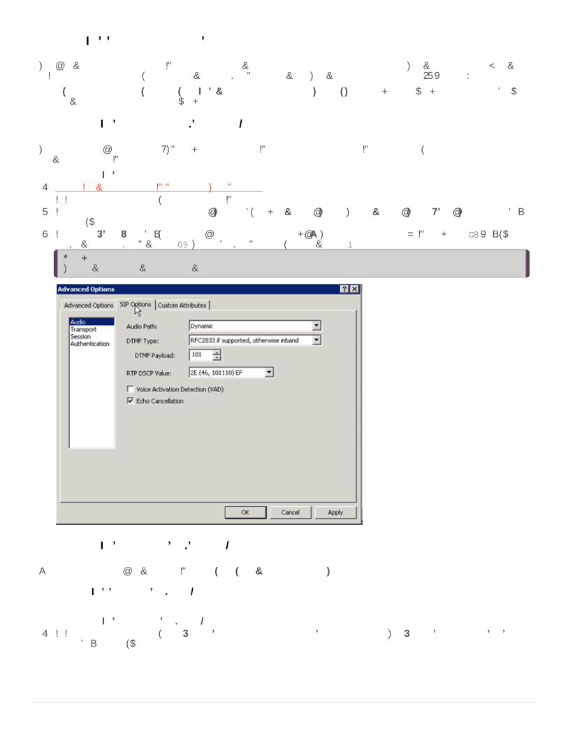
To configure the QoS setting for RTP1. Create Individual Managed IP Phones for Test Purposes.2. In Interaction Administrator, open a managed IP phone in the IP Managed Phones container.3. In the Managed IP Phone Configuration - Options tab, click Advanced Options. The Advanced Options - SIP Options dialog box
appears, with the Audio page selected.4. In the RTP DSCP Value box, specify the QoS setting and then click OK. The optimal setting for VoIP packets is B8 (hex), which
is equivalent to a DSCP value of 46. To disable DSCP tagging, set the value to 0.
Note:The provisioning server reads this value and includes it in the phone configuration file.
Configure the QoS setting for SIP (SIP lines)
You can configure the QoS value for SIP globally or by individual managed IP phone.
Configure the QoS Setting for SIP (global)
To configure the QoS setting for SIP (global)1. In Interaction Administrator, open Default Station Configuration in the Stations container. The Default Station Global SIP Station
dialog box appears, with the Audio page selected.
42
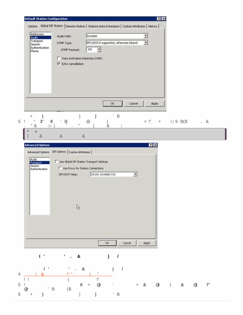
2. Click Transport in the left column. The Transport dialog box appears.3. In the SIP DSCP Value box, specify the QoS setting. The optimal setting for VoIP packets is 60 (hex), which is equivalent to a
DSCP value of 24. To disable DSCP tagging, set the value to 0.
Note:The provisioning server reads this value and includes it in the phone configuration file.
Configure the QoS setting for SIP (individual managed IP phone)
To configure the QoS setting for SIP (individual managed IP phone)1. Create Individual Managed IP Phones for Test Purposes.2. In Interaction Administrator, open a managed IP phone in the IP Managed Phones container.3. In Managed IP Phone Configuration, click the Options tab and then click Advanced Options. The Advanced Options - SIP
Options dialog box appears, with the Audio page selected.4. Click Transport in the left column. The Transport dialog box appears.
43

5. Clear the Use Global SIP Station Transport Settings check box. The SIP DSCP Value box is available.
6. In the SIP QOS Byte box, specify the QoS setting. The optimal setting for VoIP packets is 60 (hex), which is equivalent to aDSCP value of 24. To disable DSCP tagging, set the value to 0.
Note:The provisioning server reads this value and includes it in the phone configuration file.
Individual Managed IP Phones for Test Purposes
Genesys recommends creating individual managed IP phones for the appropriate managed IP phone types in your CIC system fortest purposes, before proceeding with a full managed IP phone implementation. Create at least one individual managed IP phone foreach of the managed IP phone types that you plan to implement and configure for your test purposes.
To create individual managed IP phones1. Open Interaction Administrator, right-click in the Managed IP Phones container, and then click New
Create Individual Managed IP Phones for Test Purposes
44
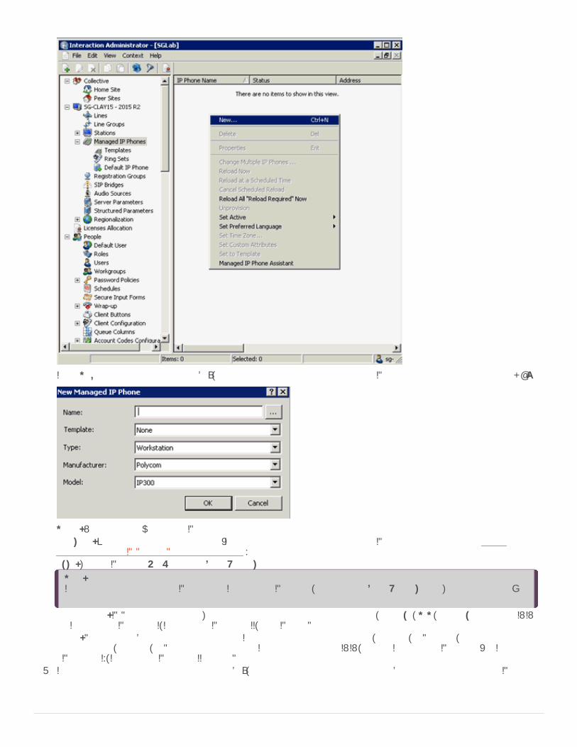
2. In the New Managed IP Phone dialog box, type the information for the first managed IP phone type to create and then click OK.
Name: Name of the new managed IP phone.Template: Keep the default setting of none. (It is not necessary to create a managed IP phone template until you CreateMultiple Managed IP Phones Procedure Summary.)Type: Type of IP phone: Workstation or Stand-alone phone.
Note:If you are creating a managed IP phone for Interaction SIP Station, do not select Stand-alone phone. The system doesn'tsupport it.
Manufacturer: IP Phone manufacturer. The supported manufacturers are AudioCodes, Genesys, ININ, and Polycom. Select ININfor Interaction SIP Station I, Interaction SIP Station II, and SIP Soft Phone.Model: Phone model based on the manufacturer. If the manufacturer is AudioCodes, Genesys, or Polycom, choose from a listof AudioCodes, Genesys, or Polycom phone models. If the manufacturer is ININ, choose Interaction SIP Station (for InteractionSIP Station I), Interaction SIP Station II or Soft Phone.
3. In the Managed IP Phone Configuration dialog box, type the information on the General tab to define for this managed IP phonetype for test purposes.
45

Name: Unique name of this IP phone.Active: Keep the default setting of Active for this managed IP phone.MAC Address (Polycom, Interaction SIP Station I and II, AudioCodes, Genesys): MAC Address in the following format:xx:xx:xx:xx:xx:xx. Polycom addresses start with 00:04:f2. Interaction SIP Station MAC addresses start with 00:26:fd.AudioCodes and Genesys addresses start with 00:90:8f.
Full Computer Name: (SIP Soft Phone) Type the full computer name of the managed IP phone. The correct full computer name ison the SIP Soft Phone user's computer. To see the full computer name, click My Computer -> Properties -> Computer Name. Forexample: PattyJ.acme.com or PattyJ.
Registration: Select Registration Group. Depending on your implementation and what you plan to test, it may be necessary tomodify the default registration group. For more information, see Registration Groups.
Location: Keep the default location unless you plan to test multiple locations. Besides reading SNTP settings from the phone,the CIC server uses the location settings to determine the codecs to use for the phone’s audio during the call.
Firmware Version: Firmware version for this managed IP phone. By default, the recommended option of <Latest> is selected.Older firmware versions installed previously on this system can also appear in the list box. In certain scenarios, you can selectolder approved firmware for this phone model. For example, to control the rollout of new firmware to a managed IP phone orgroup of managed IP phones during a release update.
Note:If the selected managed IP phone model does not support the selectable firmware feature, this option isn't available.
Audio Protocol (Polycom, SIP Soft Phone, Interaction SIP Station I and II, AudioCodes, Genesys): The system can unencrypt theaudio stream on this IP phone using RTP (Real Time Protocol) or encrypt it using Secure RTP (SRTP). If you plan to useTLS/STRP, select STRP. Otherwise, leave the default setting of RTP. (Certain Polycom IP phone models do not support thisaudio protocol option; therefore, this option doesn't appear.)
Time Zone (Polycom, Interaction SIP Station I and II, AudioCodes, Genesys): The time zone that set here passes to the phoneduring configuration. This option overrides the setting that is in the phone’s configuration.
46

Note:You can also configure the time zone for these three managed IP phone types with Options 002, 004, and 042 on the DHCPserver.
Station Appearances: As part of creating managed IP phones, you create associated SIP station appearances on those IPphones. Proceed to step 4 to configure the station appearance for this managed IP phone.
4. Under Station Appearances on the Managed IP Phones Configuration General tab, click Edit to open the Station Configurationfor the selected managed IP phone.
5. On the Station Configuration-Configuration tab, type the information to define for the station appearance for test purposes.
Extension: Extension number for this station appearance.Changes to other Configuration tab settings are optional. For more information, see the Interaction Administrator Help.
6. Click the Station Configuration-Licensing tab.
47

The system assigns a Basic Station License by default to the SIP station appearance associated to the managed IP phone.Assign other licenses, such as Client Access and ACD Access, as needed for test purposes.
7. Click OK to return to the Managed IP Phone Configuration dialog box.8. To configure additional options for the managed IP phone for test purposes, see the Managed IP Phone Configuration-Options
tab. The available options vary, depending on the managed IP phone type.
48

For more information about these Polycom configuration options, see the Interaction Administrator Help.
Note:If you have not configured QoS for RTP and SIP as described in Implement QoS in Your Environment, do so now.
9. Repeat the previous steps to create a managed IP phone for the other managed IP phone types you plan to implement.
Every managed IP phone requires a registration group. The registration group controls who the phone registers and communicateswith. Each registration group consists of an ordered list of registrations. Each registration either points to a line, is specifiedmanually, or is obtained from a SIP proxy or DNS SRV. A managed IP phone attempts to use the first registration. If it fails, it usesthe second one. If it fails again, it attempts to use the subsequent registrations.
Depending on your implementation and what you plan to test, you might have to modify the registration group configuration for theindividual managed IP phones that you create for test purposes.
View Default Registration Group SettingsRegistration Group Configuration for TLS/STRP and/or Switchover
View Default Registration Group Settings
As part of the CIC installation, IC Setup Assistant created two permanent default registration groups:<Default Registration Group> for the default <Stations-UDP> line<Default Secure Registration Group> for the default <Stations-TLS> line
To view the <Default Registration Group> settings1. In the Interaction Administrator Managed IP Phones container, click Registration Groups.2. Right-click <Default Registration Group> and then click Properties.3. In the Registration Group Configuration dialog box, note that only one registration appears under Registrations. You can add
more registrations for redundancy.
Note:A registration group cannot have more than one SIP Line registration. If a registration group does have a SIP Lineregistration, it must be the first entry in the list.A registration group cannot have more than one DNS SRV registration. If a registration group does have a DNS SRVregistration, it must be the first entry in the list.
4. Click the listed registration and then click Edit to view the registration settings.
Registration Groups
49
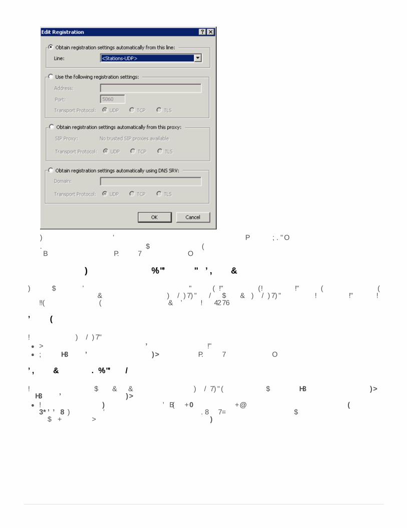
This registration is set to obtain registrations automatically from the default <Stations-UDP> line.Depending on your implementation and what you plan to test, you may need to create additional registrations or modify theexisting registration for the <Default Registration Group>.
Registration Group Configuration for TLS/STRP and/or Switchover
The following describes registration group configuration for Polycom, SIP Soft phones, Interaction SIP Station, AudioCodes phones,and Genesys phones in environments implementing TLS/STRTP and/or Switchover. TLS/STRTP support for Interaction SIP Station Iand II, AudioCodes phones, and Genesys phones is available in CIC 2016 R4 and later.
Security settings
If you plan to use TLS/STRP:Ensure that the Audio Protocol is set to SRTP for the managed IP phone.Use the <Default Secure Registration Group> instead of the <Default Registration Group>.
Switchover settings (TLS/SRTP)
If you are configuring a Switchover environment and are using TLS/SRTP, modify the following for the <Default Registration Group>or <Default Secure Registration Group>:
In the Registration Group Configuration dialog box, click Edit and then click Obtain registration settings automatically usingDNS SRV. This option obtains registration settings from the DNS SRV records that you created when you configured thenetwork the phone. Ensure that you select the appropriate Transport Protocol for this registration group.
50

If your Switchover environment requires remote survivability (for example, a remote office using a SIP Proxy), click Add… in theRegistration Group Configuration dialog box to add another registration to the <Default Registration Group>. In the AddRegistration dialog box, click Obtain registrations settings automatically from this proxy. Ensure that you select the appropriateTransport Protocol for this registration group.
Interaction SIP Station I and II, AudioCodes, and Genesys phone support for DNS SRV
Interaction SIP Station I supports DNS SRV in CIC 4.0 SU 4 to SU 6 and CIC 2015 R1 and later, which containsv.1.2.2._p10_build_17 or later firmware.Interaction SIP Station I and II support DNS SRV in CIC 2015 R2 and later which contains v.2.0.4.15.7 or later firmware.AudioCodes and Genesys phones support DNS SRV in CIC 4.0 SU 6 and CIC 2015 R1 and later, which contains v2.2.277.2.3 orlater firmware.
Note:Interaction SIP Station I and II, AudioCodes, and Genesys phones support only a single registration entry: either DNS SRV or astations line.
Limitations
Interaction SIP Station I and II, AudioCodes, and Genesys phones have the following registration group configuration limitations:Interaction SIP Station I and II, AudioCodes, and Genesys phones do not support multiple entries (registrations) in a registrationgroup.
Note:Starting with CIC 2016 R1, firmware updates with a version of 2.2.2.77 or higher for Interaction SIP Station I and II remove theconstraint of registering the phone with a single server.
Switchover settings (SIP Station I and II, AudioCodes, or Genesys phones)
Switchover environments that use only Interaction SIP Station I and II, AudioCodes, or Genesys phones do not need to modify the<Default Registration Group>.
However, if the Switchover environment includes Interaction SIP Station I and II, AudioCodes, Genesys, Polycom, or SIP Soft
51
phones, follow this example to create separate registration groups specifically for the Interaction SIP Station I and II, AudioCodes,and/or Genesys phones.
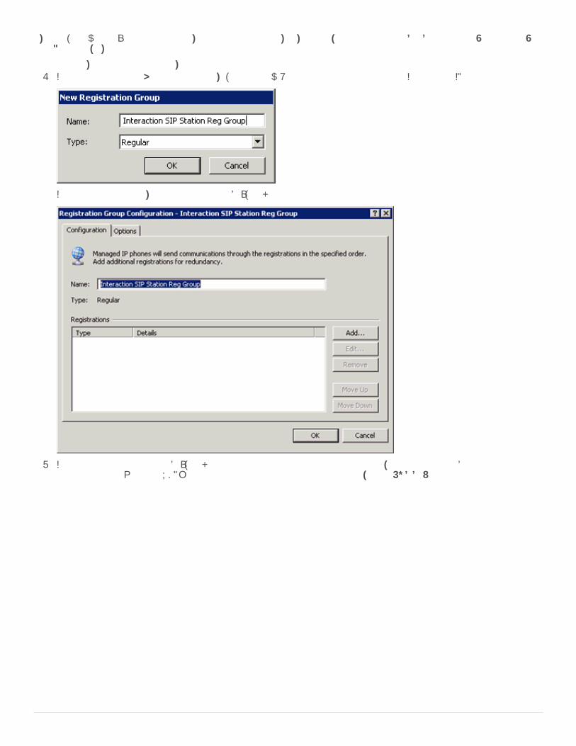
To create separate registration groups1. In Managed IP Phones > Registration Groups, create a new Regular registration group for the Interaction SIP Stations.
2. In the Registration Group Configuration dialog box, click Add
3. In the Add Registration dialog box, click either obtain registration settings automatically from this line to obtain registrationsettings from the <Stations-UDP> line or obtain registration settings automatically using DNS SRV.
52

Create Multiple Managed IP Phones Procedure SummaryAfter you configure the network for managed IP phones, create individual managed IP phones for test purposes, and are satisfiedwith your testing, you can proceed with the full managed IP phone implementation. The implementation includes creating multiplemanaged IP phones for all IP phone types (Polycom, Interaction SIP Station I and II, SIP Soft Phone, AudioCodes, and Genesysphones) at your site.
Note:You can migrate or recreate existing unmanaged Polycom phones and SIP Soft Phones as managed IP phones.
The recommended procedure for creating new managed IP phones is to use the Managed IP Phone Assistant in InteractionAdministrator to create multiple managed IP phones and associated SIP stations. The procedure consists of the following steps:1. Create one or more managed IP phone templates based on managed IP phone type, manufacturer, model, location, language,
audio protocol, station appearance, and more. For more information, see Create Managed IP Phone Templates.2. Create one or more CSV Managed IP Phone Lists based on 1) Template containing name, template, proxy group, extension,
identification address, label, and address information for the appropriate IP phones in your CIC system, and/or 2) Type,Manufacturer, and Model containing name, type, model, manufacturer, proxy group, extension, identification address, label, andaddress information for the appropriate IP phones in your CIC system. For more information, see Create CSV Managed IPPhone Lists.
3. Run the Managed IP Phone Assistant in Interaction Administrator to create new managed IP phones and associated SIPstations by importing the CSV Managed IP Phone list(s). For more information, see Create Managed IP Phones with ManagedIP Phone Assistant.
Genesys recommends that you plan the IP phone configuration that you want for your CIC system.
If it is appropriate for your site, create one or more managed IP phone templates based on your planning decisions. For example,you might want to create separate templates for the following situations:
The CIC system has Polycom phones (perhaps a variety of Polycom models), SIP Soft Phones, Interaction SIP Station I and IIphones, AudioCodes, and Genesys phones.The CIC system has IP phones in a variety of locations.The audio stream on certain IP phones unencrypts using RTP, and others encrypt using SRTP.Certain IP phones have regular station appearances, and others have shared station appearances.
Create Managed IP Phone Templates
53

Note:Templates are most useful for significant quantities of the phones of the same type, manufacturer, model, and more. Forexample, if your site has 30 Polycom IP335 phones; one IP7000 conference phone (for a conference room); one IP670 phone(for the CEO); and one IP650 for the receptionist, Genesys recommends using a template for the IP335's but not for the otherthree phones.
To create managed IP phone templates1. In the Interaction Administrator Managed IP Phones container, click Templates, right-click in the right pane, and then click New.
The New Managed IP Phone Template dialog box appears.
Name: Name of the new managed IP phone template.Type: Type of IP phone for this template Workstation or Stand-alone Phone. The default is Workstation.
Note:For Interaction SIP Station phones I and II, select Workstation. (These phones don't support the Stand-alone Phone option).
Manufacturer: IP Phone manufacturer. The supported manufacturers are AudioCodes, Genesys, ININ, and Polycom. Click ININfor Interaction SIP Station I and II and SIP Soft Phone.Model: Phone model based on the manufacturer. If the manufacturer is AudioCodes, Genesys, or Polycom, choose from a listof AudioCodes, Genesys, or Polycom phone models. If the manufacturer is ININ, choose Interaction SIP Station (for InteractionSIP Station I), Interaction SIP Station II, or Soft Phone.
2. Complete the information for the first managed IP phone template to create and then click OK. The Managed IP PhoneTemplate Configuration dialog box appears.
54
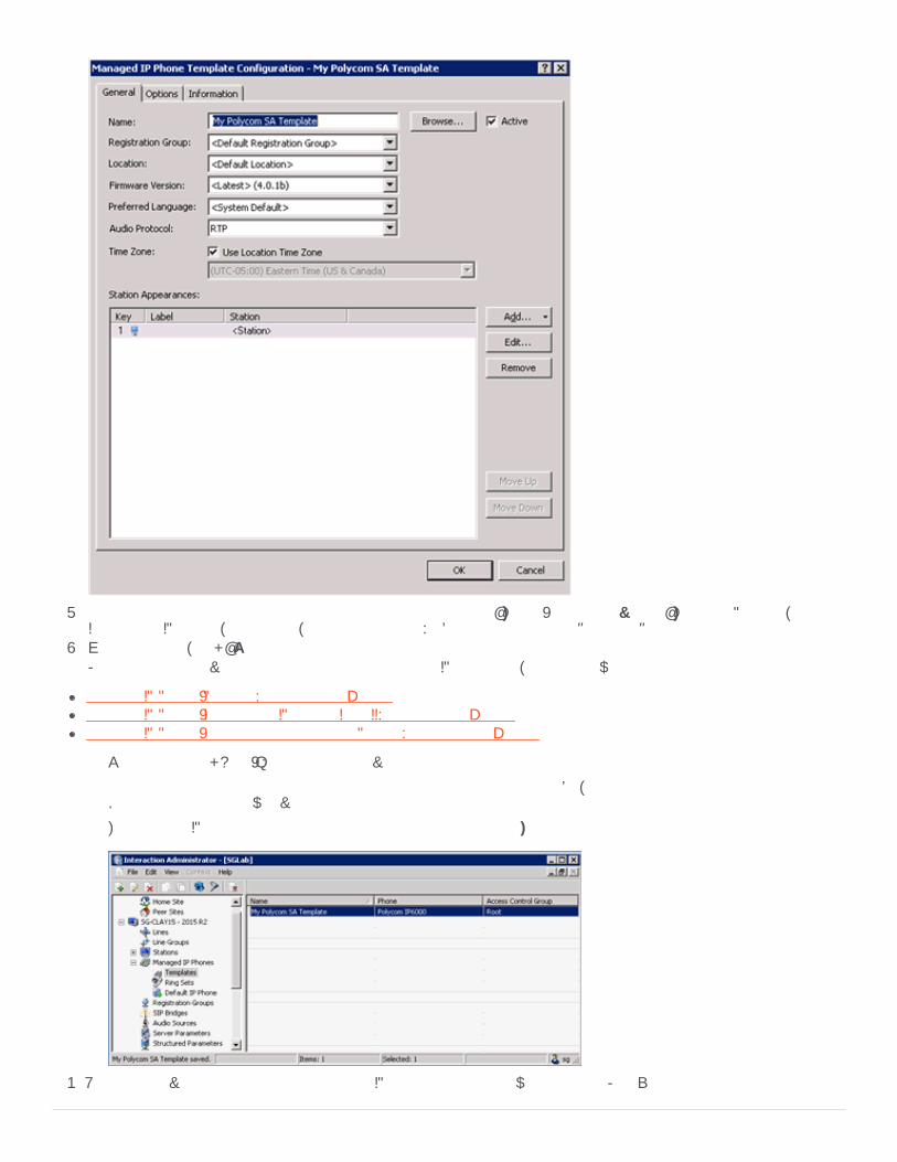
3. Select or add the appropriate configuration items on the General and Options (including Advanced Options for Polycom,Interaction SIP Station, AudioCodes,and Genesys phones) tabs for this managed IP phone template.
4. When completed, click OK.For a summary of advanced configuration features for each IP phone type, see the following:
Managed IP Phone (Polycom) Configuration OptionsManaged IP Phone (Interaction SIP Station I and II) Configuration OptionsManaged IP Phone (AudioCodes and Genesys Phones) Configuration Options
You can also click Help (?) for details on individual configuration items.
Genesys recommends that you specify as many configuration items as possible, instead of using the default settings.Defining the template now saves you time later.
The managed IP phone template appears in Managed IP Phones...Templates.
5. Repeat the previous steps for the other managed IP phone templates you want to create. For example:
55

Once you create a managed IP phone template, create one or more CSV Managed IP Phone lists based on one or both of thefollowing:
Template: Containing name, template, proxy group, extension, identification address, label, and address information for theappropriate IP phones in your CIC system. Each IP phone must reference one of the managed IP phone templates you createdby name. For more information, see Create a CSV Managed IP Phone Template List.Type, Manufacturer, and Model containing name, type, manufacturer, model, proxy group, extension, identification address,label, and address information for the appropriate IP phones in your CIC system. For more information, see Create a CSVManaged IP Phone TMM List.
Two sample CSV Managed IP Phone lists corresponding to the two types of CSV lists are available to download from the Utilitiesand Downloads page:
CSV Managed IP Phone List-Template.csv and CSV Managed IP Phone List-Template.xlsxCSV Managed IP Phone List-TMM.csv and CSV Managed IP Phone List-TMM.xlsx
When you run Managed IP Phone Assistant, you import a completed CSV Managed IP Phone list.
Create a CSV Managed IP Phone Template List
Follow this procedure to create a CSV managed IP phone list based on a template.
To create a CSV Managed IP Phone-Template list1. Download the most recent sample CSV Managed IP Phone Lists from the Utilities and Downloads page to the CIC server or
location accessible by the CIC server.2. Open a copy of CSV Managed IP Phone List-Template.xlsx and specify the attributes in the appropriate columns for
each managed IP phone and associated SIP station to create.
The following table provides descriptions of each attribute.
Create CSV Managed IP Phone Lists
56

Attribute Description
Name (Required) Name of the IP phone.
Template (Required) Managed IP phone template for this IP phone. Ensure that the template name is identical to one ofthe templates that you created.
Proxy Group Registration (Proxy) Group to use with the managed IP phone template for this IP phone.If this value is blank, Managed IP Phone Assistant fills in the Registration Group defined in the template.
Extension Primary appearance extension number for this IP phone.If this value is blank, it remains blank in Managed IP Phone Assistant.
IdentificationAddress
SIP connection address in the form of sip: xxx@ IPaddress: portnumber . For example,sip:[email protected]:5060.If you do not know the IP address, leave this value blank. It populates when the phone registers with the CICserver following provisioning.
Label (Polycom only) Label to use for the primary appearance of this IP phone and the associated SIP station.Typical values for "label" are the station extension or the user's extension (in the case where one user almostalways uses the station).If this value is left blank, Managed IP Phone Assistant fills in the Name attribute (IP phone name).
Address If you know the address for this IP phone ahead of time, specify one of the following:For Polycom phones: MAC address of the IP phone. Polycom addresses start with 00:04:f2.For SIP Soft Phones: Full computer name for the IP phone. To ensure that you get the full computer name,click My Computer>Properties>Computer Name. For example: PattyJ.acme.com.For Interaction SIP Station I & II phones: MAC address of the IP phone. Interaction SIP Station MACaddresses start with 00.26.fd.For AudioCodes and Genesys phones: MAC address of the IP phone. AudioCodes and Genesys phoneaddresses start with 00:90:8f.
If you do not know the address ahead of time:For Polycom phones: Provision the phones manually using the provisioning IVR.For SIP Soft Phones: Provision the phones manually using the SIP Soft Phone Provisioning wizard.For Interaction SIP Station I phones: You cannot provision the Interaction SIP Station I through theprovisioning IVR. If you didn't know the MAC address when you created the CSV list, specify the MACaddress manually for each Interaction SIP Station I in the Interaction Administrator Managed IP Phonecontainer before setting up and booting the corresponding phone.For Interaction SIP Station II phones: Provision the phones manually using the provisioning IVR.For AudioCodes and Genesys phones: Provision the phones manually using the provisioning IVR.
3. After specifying the IP phone information, save the file, selecting .CSV as the file type. The following message can appear whensaving the CSV Managed IP Phone list:
Ignore this message and click Yes. The message explains that some of the macros in the Excel file cannot be preserved in theresulting CSV file. You don't need those macros when Managed IP Phone Assistant imports the file.Following is an example of the resulting CSV Managed IP Phone List.csv file as it appears in Excel:
When opening the CSV file in a text editor, the IP phone information is separated by commas, with one IP phone listed per line.
57

4. If you have not already done so, download your CSV Managed IP Phone list-Template.csv file to a secure location onthe CIC server.
Create a CSV Managed IP Phone TMM List
Complete this procedure to create a CSV managed IP phone list based on type, manufacturer, and model.
To create a CSV Managed IP Phone-TMM list1. Download the most recent sample CSV Managed IP Phone Lists from the Utilities and Downloads page to the CIC server or
location accessible by the CIC server.2. Open a copy of CSV Managed IP Phone List-TMM.xlsx and specify the attributes in the appropriate columns for each
managed IP phone and associated SIP station to create.
The following table provides descriptions of each attribute.
58

Attribute Description
Name (Required) Name of the IP phone.
Type (Required) Type of IP phone - Workstation or Stand-alone Phone.For Interaction SIP Station I and II phones, specify Workstation as these types don't support stand-alonephones.
Manufacturer (Required) IP phone manufacturer.The supported manufacturers are AudioCodes, Genesys, ININ, and Polycom.
Model (Required) Phone model based on the manufacturer.If the manufacturer is Polycom, specify Polycom phone model.If the manufacturer is ININ, specify Soft Phone or Interaction SIP Station (for Interaction SIP Station 1),Interaction SIP Station II.If the manufacturer is AudioCodes, specify the AudioCodes phone model.If the manufacturer is Genesys, specify the Genesys phone model.
Proxy Group Registration (Proxy) Group to use with the managed IP phone template for this IP phone.If this value is blank, Managed IP Phone Assistant fills in the default Registration Group.
Extension Primary appearance extension number for this IP phone.If this value is blank, it remains blank in Managed IP Phone Assistant.
IdentificationAddress
SIP connection address in the form of sip:xxx@IPaddress:portnumber. For example,sip:[email protected]:5060.If you do not know the IP address for this phone, leave this value blank. It populates when the phone registerswith the CIC server following provisioning.
Label (Polycom only) Label to use for the primary appearance of this IP phone and the associated SIP station.Typical values for Label are the station extension or the user's extension (in the case where one user almostalways uses the station).If this value is blank, Managed IP Phone Assistant fills in the Name attribute (IP phone name).
Address If you know the address for this IP phone ahead of time, specify one of the following:For Polycom phones: MAC address of the IP phone. Polycom addresses start with 00:04:f2.For SIP Soft Phones: Full computer name for the IP phone. To ensure that you get the full computer name,click My Computer>Properties>Computer Name. For example: PattyJ.acme.com.For Interaction SIP Station I and II phones: MAC address of the IP phone. Interaction SIP Station MACaddresses start with 00.26.fd.For AudioCodes or Genesys phones: MAC address of the IP phone. AudioCodes and Genesys phoneaddresses start with 00:90:8f.
If you do not know the address ahead of time:For Polycom phones: Provision the phones manually using the provisioning IVR.For SIP Soft Phones: Provision the phones manually using the SIP Soft Phone Provisioning wizard.For Interaction SIP Station I phones: You cannot provision the Interaction SIP Station I through theprovisioning IVR. If you didn't know the MAC address when you created the CSV list, specify the MACaddress manually for each Interaction SIP Station I in the Interaction Administrator Managed IP Phonecontainer before setting up and booting the corresponding phone.For Interaction SIP Station II phones: Provision the phones manually using the provisioning IVR.For AudioCodes and Genesys phones: Provision the phones manually using the provisioning IVR.
3. After you complete the IP phone information, save the file, selecting .CSV as the file type. The following message can appearwhen saving the CSV Managed IP Phone list:
Ignore this message and click Yes. The message explains that some of the macros in the Excel file cannot be preserved in theresulting CSV file. You don't need those macros when Managed IP Phone Assistant imports the file.Following is an example of the resulting CSV Managed IP Phone List.csv file as it appears in Excel:
59

When opening the CSV file in a text editor, the IP phone information is separated by commas, with one IP phone listed per line.
4. If you have not already done so, download your CSV Managed IP Phone list-TMM.csv file to a secure location on theCIC server.
The Managed IP Phone Assistant guides you through the process of creating multiple managed IP phones and associated SIPstations from an imported CSV Managed IP Phone list. For more information, see the Interaction Administrator Help.
Note:Genesys recommends that you run the Managed IP Phone Assistant outside of your core business hours because theprocedure requires significant server resources.
To create managed IP phones with Managed IP Phone Assistant1. In the Managed IP Phones container in Interaction Administrator, right-click in the right pane and then click Managed IP Phone
Assistant.
The Managed IP Phone Assistant Welcome page appears.
Create Managed IP Phones with Managed IP Phone Assistant
60

If you are running Managed IP Phone Assistant after business hours, a confirmation message appears, asking whether youwant to run the wizard during business hours. Click Yes.
2. Click Next. The Add Managed IP Phones page appears.
3. Click Create managed IP phones from a .CSV file. The Create Managed IP Phones from a CSV file page appears.
61

4. Browse to the location of your CSV Managed IP Phone List.csv file(s) on the CIC server, select the .csv file to import,and then click Next.
If the assistant encounters errors while parsing the CSV file, a message appears, indicating such. Click Errors to view the statusof the errors and a description.Warning error: Managed IP Phone Assistant cannot verify one or more values. You can continue with the import, but some ofthose values don't import.Severe error: Managed IP Phone Assistant detects no columns or it couldn't open the file. You cannot continue with the import.If you imported a CSV list based on type, manufacturer, and model (CSV Managed IP Phone List-TMM.csv), the AccessControl page appears.
62

5. Select the dial plan classifications for the managed IP phones and station appearances in the CSV file. For more information,click Help (?).
Note:If you imported a CSV list based on template, this page doesn't appear because you defined the dial plan classifications inthe template.
6. Click Next. The Saving Managed IP Phones page appears. To change your settings, click Back.
7. Click Commit Changes. If you imported a CSV list based on type, manufacturer, and model (CSV Managed IP Phone List-TMM.csv), the Station Appearances Licenses page appears.
63
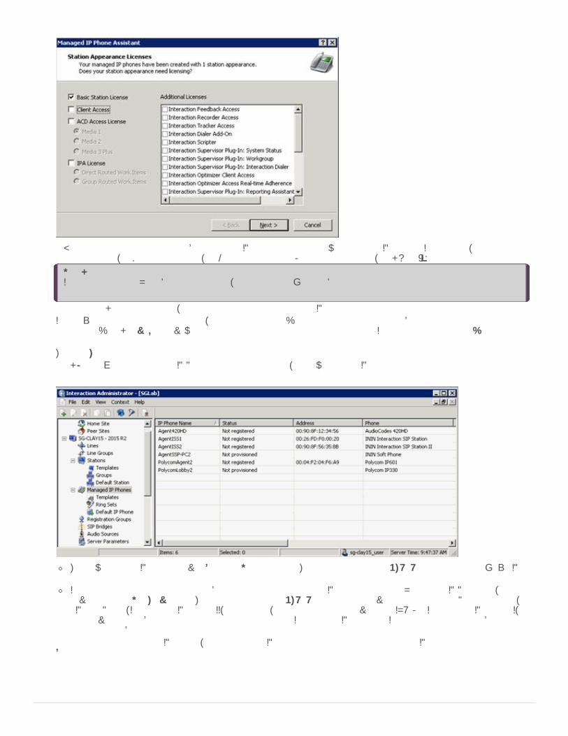
A Basic Station license is assigned by default to SIP stations associated with managed IP phones. If necessary, assign ClientAccess licenses, ACD Access licenses, and/or add-on licenses. For more information, click Help (?).
Note:If you imported a CSV list based on template, this page doesn't appear because you defined the station appearancelicensing in the template.
After you click Commit Changes, the assistant prepares the managed IP phones and applies licenses.If you exceed the total count of licenses, a message appears: "Some or all licenses could not be allocated to each stationappearance". Click Review to review the errors and then correct the information in the Interaction Administrator LicenseAllocation container.The Completed the Managed IP Phone Assistant page appears.
8. Click Finish. When the Managed IP Phone Assistant completes, the new managed IP phones appear in the Managed IP Phonescontainer.
The new managed IP phones have a Status of Not registered. Their status changes to Up-to-date on the phones' next SIPregistration.If you did not specify the Address attribute for one or more managed IP phones in your CSV Managed IP Phone list, theyhave a status of Not provisioned. Their status changes to Up-to-date once you provision them using the Polycom phone,SIP Soft Phone, Interaction SIP Station II, AudioCodes, or Genesys phones provisioning IVR. For Interaction SIP Station I,you provision them by specifying the MAC address for each Interaction SIP Station in Interaction Administrator beforesetting up and booting the corresponding phone.
As part of creating managed IP phones, the associated SIP station appearances created on those IP phones appear in theStations container.
64

The SIP stations associated with managed IP phones are of the type Managed Workstation or Managed Stand-alone Phone.If necessary, you can assign Client Access licenses, ACD Access licenses, and add-on licenses to users on the Licensing tabnow, or in the Licenses Allocation container.
65

CIC provisioning of managed IP phones connects the managed IP phones and downloads their configurations from the CIC server.The goal for CIC Managed IP Phone provisioning is to "automate" it as much as possible so that it requires no user participation.
If you followed the instructions to configure the network and to Create Managed IP Phones with Managed IP Phone Assistant,automated provisioning occurs once you set up and boot (or re-boot)the phones.
When a managed IP phone contacts the provisioning subsystem, the provisioning system matches the phone's computer name orMAC address with an existing managed IP phone configuration, and serves the configuration to the device without any extra steps.
Manual provisioning (multiple managed IP phones)
Manual provisioning of some or all managed IP phones are necessary when:You don't specify the MAC Address (Polycom, Interaction SIP Station I and II, AudioCodes, Genesys phones) or Full ComputerName (SIP Soft Phone) in the CSV list for some or all Polycom, Interaction SIP Station I and II, SIP Soft Phones, AudioCodes,and/or Genesys phones.
Note:In an implementation of new Polycom and/or SIP Soft Phones, the MAC Address or Full Computer Name may not be knownat the time the CSV list is created.
The CIC system has no DHCP server or it cannot access the DHCP server.Some Polycom phones, Interaction SIP Station phones I and II, SIP Soft Phones, AudioCodes, and/or Genesys phones are inremote locations.
Typically, an administrator with required permissions does the manual provisioning. In some cases (for example, remote locations),users must do the manual provisioning.
To provision each managed phone's configuration manuallyFor Polycom phones: Use the provisioning IVR.For SIP Soft Phones: Use the SIP Soft Phone Provisioning wizard.For Interaction SIP Station I phones: You cannot provision the Interaction SIP Station I phones through the provisioning IVRbecause they don't have a dial pad. If you didn't know the MAC address when you created the CSV list, specify the MAC addressmanually for each Interaction SIP Station in the Interaction Administrator Managed IP Phone container before setting up andbooting the corresponding phone.For Interaction SIP Station II phones: Use the provisioning IVR since Interaction SIP Station II phones do have a dial pad.For AudioCodes and Genesys phones: Use the provisioning IVR.
Sometimes, you have to use non-standard manual provisioning procedures. For more information, see Appendix A: Non-standardProvisioning Scenarios.
Complete the Provisioning Process (Multiple Managed IP Phones)
66

Polycom Administration
Create Managed IP Phones from Existing (Polycom) SIP Stations
Note:This information is for existing CIC systems with unmanaged Polycom phones migrating to CIC 2015 R1 or later.
If your CIC system has existing "unmanaged" Polycom phones (SIP stations), Genesys recommends that you convert them tomanaged IP phones. Then, you no longer need to maintain Polycom phone configuration (.cfg) files.
Before beginning these procedures, configure the network for managed IP phones. Genesys also recommends that you CreateIndividual Managed IP Phones for Test Purposes and ensure that you are satisfied with your testing first.
The SIP Phone Information Update server parameter allows the CIC system to populate the Manufacturer and Model automaticallyfor a Polycom phone (SIP station) in Interaction Administrator. Set the SIP Phone Information Update server parameter to a value of1, yes, or true. When the phones reboot, Telephony Services derives the model and manufacturer information from the User-Agentstrings in the registration message and updates the DS attributes dynamically for the corresponding SIP Station. All Polycomphones send this information each time they register, meaning that the data populates in Interaction Administrator as each phonere-registers with the CIC server. The system uses this data when you run Managed IP Phone Assistant to convert to managed IPphones and associated SIP stations.
For the SIP Phone Information Update server parameter to take effect, reboot the phones. It takes time for all of the phones to re-register with the server, so ensure that you check to see that the values populated before proceeding.
Update the Polycom phone configuration files in the root directory of the TFTP or FTP server to include the sec.tagSerialNo="1"configuration parameter. This action allows the CIC system to populate the MAC Address automatically for a Polycom phone (SIPstation) in Interaction Administrator. Choose a common file such as xic.cfg (when using files that the ININ IP PhoneConfigurator generated), or the sip.cfg file. When you update the .cfg file and reboot the phones, Telephony Services derives theMAC address from the User-Agent strings in the registration message and update the configuration dynamically for thecorresponding SIP Station. All Polycom phones send this information each time they register, meaning that the data populates inInteraction Administrator as each phone re-registers with the CIC server. The system uses this data when you run Managed IPPhone Assistant to convert to managed IP phones and associated SIP stations.
For the .cfg file updates to take effect, reboot the phones. It takes time for all of the phones to re-register with the server, soensure that you check to see that the values populated before proceeding.
Use the Migrate option in the Managed IP Phone Assistant to create managed IP phones and associated SIP stations from existing(Polycom phone) SIP stations. In this procedure, a sample SIP Workstation IP335 station migrates to a new managed IP phone andassociated station.
Add the SIP Phone Information Update server parameter
Update a common .cfg file to include sec.tagSerialNo="1" configuration parameter
Create managed IP phones from existing SIP stations using Managed IP Phone Assistant
67

Notes:Genesys recommends that you run the Managed IP Phone Assistant outside of your core business hours because theprocedure requires significant server resources.The complexity and variation of XML files means that your files can have problems migrating. If this situation occurs,contact PureConnect Customer Care and open an incident. Have your logs and copies of your XML files available. You cancontinue after you open your ticket by using the phones in an unmanaged fashion until you are able to complete themigration successfully.
To create managed IP phones from existing SIP stations1. Before you begin, ensure that you know the location of the Polycom phone/SIP station configuration files (.cfg), as the
Managed IP Phone Assistant asks for this information. The .cfg file location is typically the root directory of your TFTPserver, either a local directory path or a network share. Ensure that it is accessible from the computer where you plan to run theManaged IP Phone Assistant.
2. Click the Managed IP Phones container and then click Managed IP Phone Assistant.
Note:Run the Managed IP Phone Assistant after business hours
The Managed IP Phone Assistant Welcome page appears.
3. If you are running Managed IP Phone Assistant after business hours, click Yes to proceed past the warning message.
68

The Add Managed IP Phones page appears.
4. Click Create managed IP phones by migrating existing stations to phones on a per manufacturer basis. The SelectManufacturer page appears.
5. Choose the manufacturer of the stations to migrate. Currently Polycom is the only supported manufacturer. If you selectedPolycom on the previous page, the Select Default Model page appears.
69

6. In the list box, click the default phone model to use when the system cannot derive the model from the stations on the phonesthat you are migrating.For example, SIP stations associated with a Polycom configuration file may not have a manufacturer or model set inInteraction Administrator. By selecting the default model, the Managed IP Phone Assistant knows what settings to use for themigration. In this example, the default model selected is an IP335.
Note:If you set the SIP Phone Information Update server parameter as described in an earlier section, selecting the defaultmodel on this page is unimportant. The reason is that the server parameter ensures that each phone populatesappropriately for manufacturer and model in Interaction Administrator.
The New Phone Naming page appears.
7. Specify a format string that indicates the name for the assistant to use for the migration item. The assistant creates anassociated SIP station with the same name. There are two different substitution strings that you can use alone or with a formatstring to create phone names.Phone name format: Name of the first private station display name added to the migration item. Use a format string to definethe phone's name when created. Use one or more substitution strings with a format string, so that every phone created has ameaningful and unique name.There are two different substitution strings:
$FirstPrivateStation$: Name of the first private station display name as defined in the reg.x.displayName attributefound in the SIP phone's .cfg file added to the migration item.$MAC$: MAC address of the phone that you are migrating.
By default, the assistant uses the $FirstPrivateStation$ substitution string. You can use a substitution string separately, incombination with the other substitution string, in combination with a format string, or use it alone. For example:
$FirstPrivateStation$70

$MAC$$FirstPrivateStation$-$MAC$-SecondFloorSecondFloorPhone Using just text, the assistant appends the text with _1, _2, and so on after naming the first IP phoneand associated SIP station.
If a single format string of ManagedPhone is used without a substitution string, then all new phone names created would benamed ManagedPhone_1, ManagedPhone_2, etc. If the substitution string $MAC$ is used together with the format string ofManagedPhone, such as ManagedPhone - $MAC$, then the MAC address for each phone would be substituted in the newname, i.e., ManagedPhone - 0004f2008100.
Note:The substitution strings are case-sensitive. For example, if Phone - $mac$ is specified, $mac$ will not resolve to the MACaddress. The string must be entered as Phone - $MAC$ for proper MAC address resolution.
Sample phone name: Indicates how the phone name format field resolves.8. Click Show Available Substitution Strings to view the substitution strings. The Phone Configuration File Directory page appears.
Type the directory or click Browse to select the directory where the existing IP phone configuration (.cfg) files are. The .cfgfile is typically the root directory of your TFTP server, either a local directory path or a network share. Ensure that it isaccessible from the computer where you plan to run the Managed IP Phone Assistant. In this example, the location isD:\I3\IC\TFTPRoot.The Managed IP Phone Assistant searches this directory for .cfg files and displays a list of files found on the Select the Itemsto Migrate page. The assistant uses the settings in the selected .cfg files to create managed IP phone objects.For the assistant to recognize a phone configuration file, the file must:
Use the XXXXXXXXXXXX.cfg format, where XXXXXXXXXXXX is a 12-character alpha-numeric MAC address.Contain an APPLICATION XML element at the root that has a CONFIG_FILES XML attribute that specifies the other phoneconfiguration files.
Each .cfg file that meets these criteria displays as a selectable item to migrate. The assistant needs read access to thephone configuration directory specified. For more information, click Help (?).
9. Click Next. The Select the Items to Migrate page appears.
71

Select the items to migrate by clicking the items in the Available list and then clicking Add to move them to the Selected list.The items displayed in the Available list are the Polycom configuration files that the assistant found in the directory specifiedon the Phone Configuration File Directory page.
10. Select at least one item and then click Next. The Build Migration Items page appears.
This page shows that the migration process is going to begin building migration items, and it lists the number of migrationitems included in the process. In this example, there is just one migration item.
11. Click Next. After the building the migration items, the Current State of Migration Items page appears.
72

The number of items with errors, warnings, or no errors or warnings appear.Items with errors: The assistant cannot create a managed IP phone from these items. Click the Show Item Details button andreview the Build History tab to aid in resolving the error.Items with warnings: These items are candidates for migration at the current state, and the assistant may be able to create amanaged IP phone from these items.Items with no errors or warnings: These items are good candidates for migration at the current state, and the assistant willmost likely be able to create a managed IP phone from these items.
Note:Genesys strongly recommends that you click Show Item Details to review the migration item details. Item details includeinformation about the new managed phone created for the selected migration item, and information about error andwarnings listed for that migration item.
12. Click Next. The Backup Directory Services page appears.
Genesys strongly recommends that you complete a Directory Services backup. This step is the final step in the migrationprocess before the Managed IP Phone Assistant starts creating the managed IP phones based on the migration items.
13. Click Backup Directory Services to do the backup.The Directory Services backup can take several minutes. There is a timeoutset at 40 minutes. If the timeout is reached, the assistant displays The CIC server was unable to perform a backup of DirectoryServices. Either click Try Again to attempt another backup, or click Continue without making a backup.When the backup is complete, the page displays the location of the backup file, for example,D:\I3\IC\Backup\RegistryBackup_16-8-2011-458037. Take note of this location.This is the last page before the migration process starts. To learn more about what happens during the migration process,click Help (?).A confirmation message appears.
73

14. Click Yes to start the migration process. When the migration process is complete, the Migration Results page appears.
This page displays the number of managed IP phones created in the migration process and indicates whether warning or errorsoccurred.
15. Click Show Detailed Migration Results to view each step taken during the migration for each migration item.
If errors and warnings occurred, you can see at what point they occurred and why. Depending on the migration results, thesystem might ask you to reload the phones; or you can make changes to individual IP phones in the Managed IP Phonecontainer after the assistant completes and reload the phones then. For more information, click Help (?).The Managed IP Phone Assistant process is now complete.
74
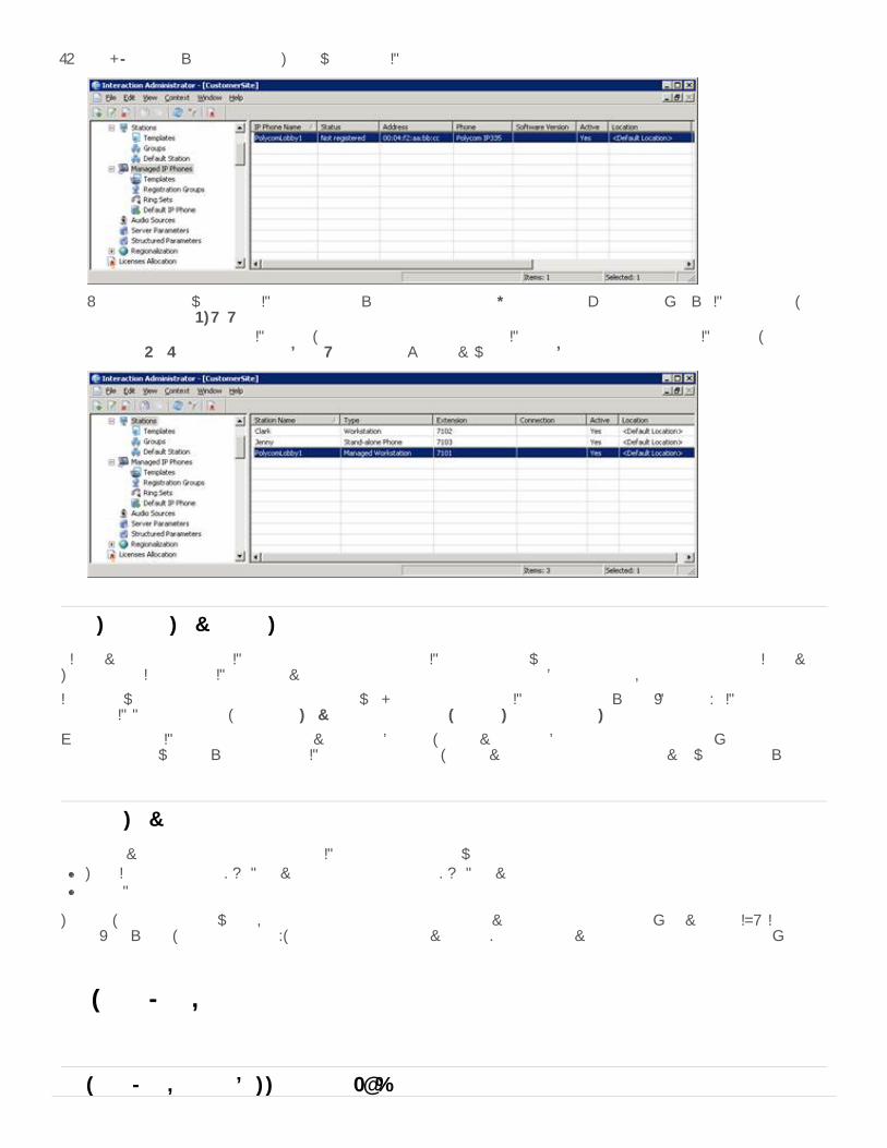
16. Click Finish to exit the assistant. The new managed IP phones appear in the Managed IP Phones container.
Notice that the new managed IP phone in this example has a status of Not registered. On the phone's next SIP registration, thisstatus changes to Up-to-date.As part of creating managed IP phones, the system creates associated SIP station appearances on those IP phones, of the typeManaged Workstation or Managed Stand-alone Phone. You can view them in the Stations container.
CIC provisioning of managed IP phones connects the managed IP phones and downloads their configurations from the CIC server.The goal for CIC managed IP phone provisioning is to automate it as much as possible so that it requires no user participation.
If you followed the instructions to configure the network and create managed IP phones from existing (Polycom) SIP stations usingManaged IP Phone Assistant, automated provisioning occurs once you set up and reboot the phones.
When a managed IP phone contacts the provisioning subsystem, the provisioning subsystem matches the phone's computer nameor MAC address with an existing managed IP phone configuration, and serves the configuration to the device without any extrasteps.
Manual provisioning of some or all managed IP phones is necessary when:The CIC system has no DHCP server or it cannot access the DHCP server.Some Polycom phones are in remote locations.
Typically, an administrator with required permissions does the manual provisioning through the phone's provisioning IVR. In somecases (for example, remote locations), users do the manual provisioning. Do manual provisioning on each managed phone'sconfiguration.
Polycom Firmware and PhonesManaged IP Phones Administrator Guide
Complete the provisioning process
Manual provisioning
Polycom Firmware for Supported and EOL Phones75

Polycom Trio 8800 with Firmware 5.9.0 revision AD voicemail issue
Polycom Trio 8800 phones with Firmware 5.9.0 revision AD reboot or change to an idle state when attempting to access voicemailin one of the following ways:
Using the one-touch featureUsing the "Voicemail" option in the Feature menu
The workaround is to set the phone's "One Touch Voicemail" option to "No" or dial the voicemail extension from the phone.
Polycom phone Firmware security vulnerability
The Polycom Support Security Center posted a notification about a security vulnerability in UC software and possible remote codeexecution. This vulnerability affects VVX, Trio, SoundStructure, SoundPoint, and SoundStation phone when the web managementinterface is enabled.
The following Polycom Firmware addresses this vulnerability:5.9.3.2857 Rev G5.9.0 Rev AD4.0.14.1580
Firmware for supported phones
The following table lists the Polycom firmware versions for supported phones.
Firmware Version Initially MadeAvailable in...
Phone Type Phone Model
5.9.3.2857 Rev G 2019 R4
2019 R3 Patch 4
2019 R2 Patch 11
2019 R1 Patch 17
2018 R5 Patch 23
2018 R4 Patch 29
2018 R3 Patch 35
Desktop Phones VVX101
VVX 150
VVX 201
VVX 250
VVX 300
VVX 301
VVX 310
VVX 311
VVX 350
VVX 400
VVX 401
VVX 410
VVX 411
VVX 450
VVX 500
VVX 501
VVX 600
VVX 601
76

5.9.0 Rev AD 2019 R4
2019 R3 Patch 4
2019 R2 Patch 11
2019 R1 Patch 17
2018 R5 Patch 23
2018 R4 Patch 29
2018 R3 Patch 35
Conference Phones Trio 8500
Trio 8800
5.8.1 2019 R2
2019 R1 Patch4
2018 R5 Patch10
2018 R4 Patch16
2018 R3 Patch23
2018 R2 Patch29
2018 R1 Patch35
Desktop Phones VVX 150
VVX 250
VVX 350
VVX 450
5.8.0 2018 R5
2018 R4 Patch3
2018 R3 Patch10
2018 R2 Patch16
2018 R1 Patch23
2017 R4 Patch29
2017 R3 Patch36
Desktop Phones (with support of VVX D60wireless handset pairing)
VVX 101
VVX 201
VVX 300/301
VVX 310/311
VVX 400/401
VVX 410/411
VVX 500/501
VVX 600/601
VVX D60
5.5.4 2018 R4
2018 R3 Patch5
2018 R2 Patch11
2018 R1 Patch18
2017 R4 Patch24
2017 R3 Patch31
2017 R2 Patch36
Conference Phones Trio 8500
Trio 8800
5.4.5G 2017 R3
2017 R2 Patch6
2017 R1 Patch12
2016 R4 Patch17
2016 R4 Patch15+ ES
2016 R3 Patch23
2016 R2 Patch23
2016 R1 Patch27
Desktop Phones VVX 101
VVX 201
VVX300/301
VVX310/311
VVX400/401
VVX410/411
VVX500/501
VVX600/601
77

4.0.14.1580 2019 R4
2019 R3 Patch 4
2019 R2 Patch 11
2019 R1 Patch 17
2018 R5 Patch 23
2018 R4 Patch 29
2018 R3 Patch 35
Desktop Phones
Conference Phones
SoundPoint
IP321
IP331
IP335
IP450
IP550
IP560
IP650
IP670
SoundStation
IP6000
IP7000
4.0.8.2058.I
(Required for new phones after June 2016 with MAC addressrange of 64:16:7f. See KB article.)
2017 R1 Patch1
2016 R4 Patch5and Patch6
2016 R3 Patch12
2016 R2 Patch17
2016 R1 Patch22
2015 R4 Patch22
2015 R3 Patch25
2015 R3 Patch24+ ES
Desktop Phones
Conference Phones
SoundPoint
IP321
IP331
IP335
IP450
IP550
IP560
IP650
IP670
SoundStation
IP6000
IP7000
5.2.2
(Default for VVX phones.)
2015 R2 Patch8
2015 R3 Patch2
Desktop phones VVX300
VVX310
VVX400
VVX410
VVX500
VVX600
4.1.6h SU6, SU5-ES,SU4-ES
Desktop phones VVX300
VVX310
VVX400
VVX410
VVX500
VVX600
78

4.0.8c 2015 R2 Patch8
2015 R3 Patch2
Desktop phones
Conference phones
IP321
IP331
IP335
IP450
IP550
IP560
IP650
IP670
IP5000
IP6000
IP7000
4.0.1b SU3 Desktop phones
Conference phones
IP321
IP331
IP335
IP450
IP550
IP560
IP650
IP670
IP5000
IP6000
IP7000
3.3.2 2020 R2
2019 R3 Patch 14
2020 R1 Patch 2
2019R4 Patch 8
2019 R3 Patch 16
Desktop phones
Conference phones
IP5000
IP335
IP321
IP331
IP450
IP550
IP560
IP650
IP670
IP6000
IP7000
79

3.2.7 SU4 Desktop phones
Conference phones
IP331
IP321
IP335
IP450
IP550
IP560
IP650
IP670
IP5000
IP6000
IP7000
Firmware for End of Life (EOL) phones
The following table lists the Polycom firmware versions for EOL phones. Genesys no longer supports the firmware and phoneprovisioning; however the phones are still available from the manufacturer.
Firmware Phone Type PhoneModel
Limitations
4.0.2b Wi-Fi phones SL8440
SL8450
3.2.7 Desktop phones IP320
IP330
IP430
3.1.6 Desktop phones
Conferencephones
IP301
IP501
IP600
IP601
IP4000
Except for the IP4000, does not support SRTP.
2.1.4 Desktop phones IP300
IP500
Does not support SRTP, DND syncing, idle screen configuration, or voice-qualitymonitoring.
Polycom firmware history
The following table shows Polycom firmware released (CIC 2015 R2 or later) and supported previously and their initial availability.
Note: Starting with CIC 2016 R4 Patch 2, CIC 2016 R3 Patch 8, CIC 2016 R2 Patch 14, CIC 2016 R1 Patch 20, CIC 2015 R4 Patch20, CIC 2015 R3 Patch 24, and CIC 2015 R2 Patch 24+, Genesys provides support for Polycom phone models VVX 301, 311, 401,411, 501, and 601. *
80

Firmware Version Initially MadeAvailable in...
Phone Type Phone Model
5.4.3.2036 (Required for new phones after June 2016 with MAC address range of64:16:7f.. See KB article.)
2017 R1 Patch 1 andlater
2016 R4 Patch 6 andPatch 7
2016 R3 Patch 13
2016 R2 Patch 18
2016 R1 Patch 22
2015 R4 Patch 22
2015 R3 Patch 25
2015 R3 Patch 24 + ES
DesktopPhones
VVX 101
VVX 201
VVX300/301
VVX310/311
VVX400/401
VVX410/411
VVX500/501
VVX600/601*
5.4.0a Use 5.4.3.2036 instead.
2016 R4 DesktopPhones
VVX 101
VVX 201
5.4.3.1014(Required for new phones after June 2016 with MAC address range of64:16:7f.. See KB article.)
Use 5.4.3.2036 instead.
2016 R3 Patch 6
2016 R2 Patch 11
2016 R1 Patch 17
2015 R4 Patch 19
2015 R3 Patch 23
2015 R2 Patch 24 + IC-138829
DesktopPhones
VVX300/301
VVX310/311
VVX400/401
VVX410/411
VVX500/501
VVX600/601
4.0.8.1972.H(Required for new phones after June 2016 with MAC address range of64:16:7f.. See KB article.)
Use 4.0.8.2058.I instead.
2016 R3 Patch 6
2016 R2 Patch 11
2016 R1 Patch 17
2015 R4 Patch 19
2015 R3 Patch 23
2015 R2 Patch 24 + IC-138829
DesktopPhones
ConferencePhones
SoundPoint
IP321
IP331
IP335
IP450
IP550
IP560
IP650
IP670
SoundStation
IP6000
IP7000
5.2.2 (Default for VVX phones.)
2015 R2 Patch 8
2015 R3 Patch 2
DesktopPhones
VVX300
VVX310
VVX400
VVX410
VVX500
VVX600
Copyright and trademark
81

Starting in June 2016, Polycom introduced a new MAC address range for VVX; SoundPoint IP and SoundStation phones; andSoundStructure Installed Audio products. The new address range replaces the 00:04:xx:xx:xx:xx MAC address range. Phoneswith a MAC address in the range 64:16:7f:xx:xx:xx require a firmware update, included in supported CIC patch releasesstarting with CIC 2015 R2. For more information, see the PureConnect KB article.
Starting with CIC 4.0 SU 3, administrators can select from a list of supported Polycom firmware versions for a specified model toapply to a managed IP phone or group of managed IP phones in Interaction Administrator.
The selectable firmware feature allows you to:Control CIC release deployment to managed IP (Polycom) phones. For example, you can leave the phones on an older firmwareversion when deploying a release. Then, set a few phones to the new firmware to test it. Then, push out all the phones whenready.Test for a regression by pushing a test phone back to an older firmware version for verification purposes.
Note:If the selected Polycom IP Phone model(s) do not support the selectable firmware feature option, the option doesn't appear.
To select a firmware version for a single managed IP phone1. Double-click a managed IP phone in the Managed IP Phones container. The Managed IP Phone Configuration dialog box
appears.
2. In the Firmware Version list box, click the firmware version. By default, the recommended option of <Latest> is selected.Older firmware versions installed on this system previously can also appear in the list box. In certain scenarios, you can selectolder approved firmware for this Polycom IP phone model. For example, to control the rollout of new firmware to a managed IPphone or group of managed IP phones during a release update. If the selected Polycom IP phone model does not support thisfeature, this option doesn't appear.
To select a firmware version for multiple IP phones
Polycom Firmware Update Required
Selectable Polycom Firmware
82

1. Click two or more managed IP phones in the Managed IP phones container, right-click, and then click Change Multiple IPPhones.
2. From the Firmware Version menu, click the firmware version. By default, the recommended option of <Latest> is selected.
The SpectraLink SL8440 and SL8450 Wi-Fi models differ significantly from the other Polycom phone models. The most basicdifference is the wireless connectivity capability of the SpectraLink phones through Wi-Fi. Along with supporting 802.11b/g/n, theyalso support WEP, WPA, WPA2-PSK, and WPA2-Enterprise for wireless security. They also require business class wireless accesspoints that support WMM (Wi-Fi Multimedia) protocols, requiring extra steps of Wi-Fi connectivity configuration before DHCP/DNSsetup.
It is also important to note that the firmware and provisioning of these devices are "End of Life" (EOL), so newer supported firmwareversions are not available. For a complete list of supported standards and recommended practices, see the Polycom productdocumentation.
SpectraLink Wi-Fi Phone Considerations
83
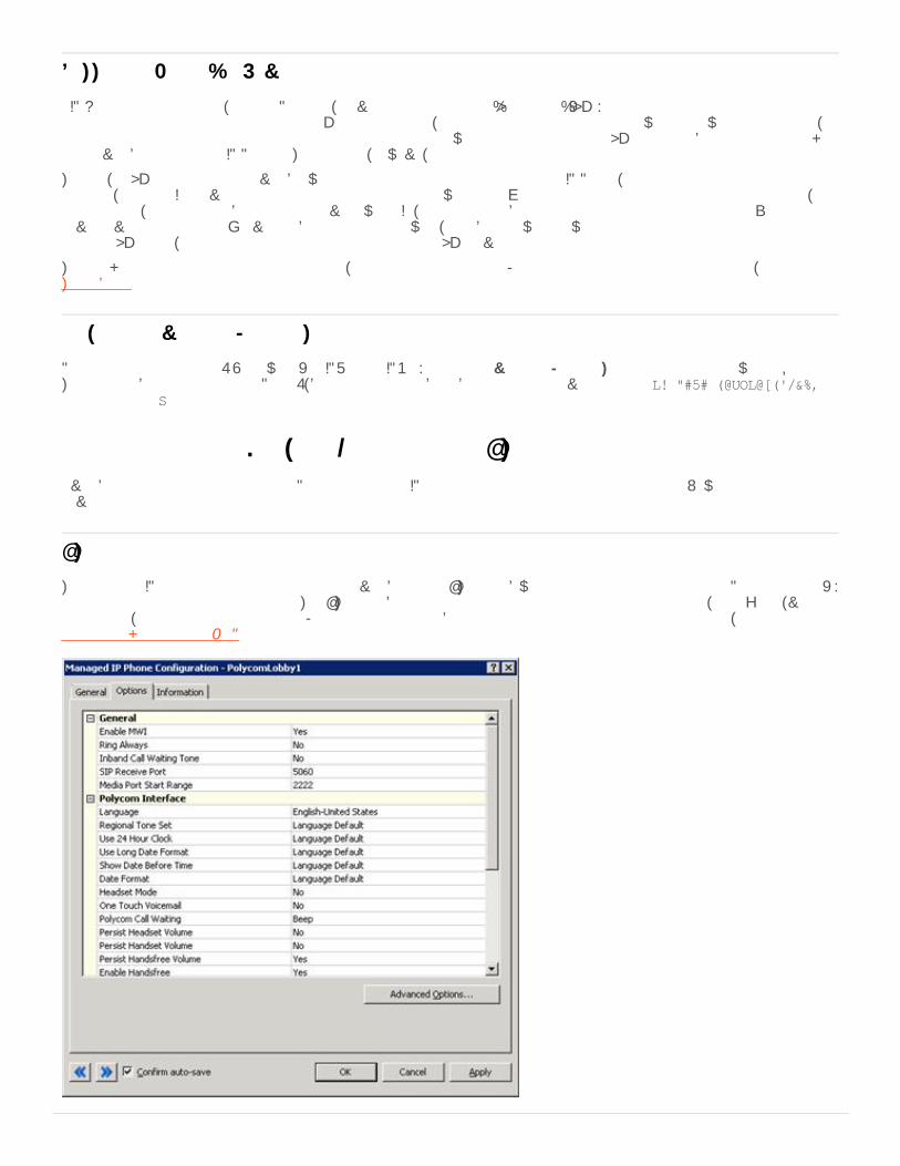
SIP Handset manufacturers, such as Polycom, move their products to an "End of Life" (EOL) status sometime after they stopproduction of that particular product model. Once this happens, they also stop maintaining the firmware used with those models,typically. Genesys has opted to attempt to support our customers who still operate on these EOL handsets by continuing to makethem available as Managed IP Phones. This support, however, is limited.
To date, all EOL phones are still available when selecting the model of your Managed IP Phone, their configuration files stillgenerate, and the CIC server still includes the last supported firmware files. While Genesys opted to support the administration,configuration, and interoperability of these devices with CIC, Genesys is unable to address any issues determined to exist at thedevice level. Genesys doesn't have the ability to create firmware, nor obtain newer firmware from the manufacturers for productslisted as EOL. Also, Genesys can discontinue the support of any EOL device for any reason in the future.
To check the status of a particular phone model, consult the manufacturer. For the latest phones that Genesys tested, see theTestlab site.
Polycom phones running 2.1.4 firmware (the IP300 and IP500) use the Provisioning FTP Adapter for their initial firmware requests.This adapter by default listens on Port 21, but you cannot disable it by creating the server parameter Provision FTP Enabledand setting it to No.
Managed IP Phone (Polycom) Configuration OptionsAvailability of configuration options for Polycom managed IP phones depends on the model of the phone. Newer models tend tohave more options.
The managed IP phone configuration options are available on the Options tab when editing one or more managed Polycom phone(s)from the Managed IP Phones container. The Options tab contains configuration options such as port settings, localization, volumepersistence, and emergency information. For more information about the configuration options and their meaning, see theInteraction Administrator Help.
Support for End of Life Devices
Polycom Provisioning FTP Adapter
Options tab
84

The managed IP phone configuration advanced options are available on the Advanced Options tab when editing one or moremanaged Polycom phone(s) from the Managed IP Phones container. The Advanced Options tab contains configuration options fortimeout, Polycom features, echo/noise suppression, gain settings, auto-dial, local Polycom dial plan, Network Address Translation(NAT), flash parameters, syslog, voice quality monitoring, and phone-specific SIP security. For more information about theadvanced configuration options and their meaning, see the Interaction Administrator Help.
Other Managed IP Phone (Polycom) FeaturesFollowing are some of the unique features that Polycom phones offer over other managed IP phones types.
Call parking places a parked call (held call) into a specific call queue, or orbit. Any other Polycom phone can pick up the parked callby specifying which orbit to pick up from.
Zone paging allows one phone to page an entire dial group (through an extension). It passes one-way audio to all phones reachableat the specified extension.
Dial string Function
*901 <extension> Zone page
*902 <orbit#> Park call in orbit <orbit#>
*903 <orbit#> Pick up parked call from orbit <orbit#>
*904 (<orbit#>) List parked calls (in orbit <orbit#>)
Dial options for Call parking and Zone paging
Polycom phones support shared line appearances, allowing mirroring of one line over multiple stations. For example, an assistanthas an appearance of the manager's phone line on their phone so that the assistant can see whether the manager is on the phone,and answer the manager's calls.
Advanced Options
Call parking / Zone paging
Shared line appearances
85

The first step for setting up shared lines is to set the desired stations as sharable. Only stations on Polycom phones support thisfeature. Use Interaction Administrator to edit the station appearance on a managed Polycom IP phone.
After you set the station to Sharable, you can add it to the Polycom managed IP phone as a shared station appearance. Select thestation appearance and a dialog box appears with the configuration of the shared appearance. Afterward, reboot the phone with theshared appearance.
86

The provisioning server supports the ability to add a custom attribute to Polycom phones named config_files (case-insensitive),which must contain a comma-separated list of files. If the file exists in the \i3\ic\provision\polycom directory on the CICserver, provisioning includes the files in the config_files list for Polycom phones. The system requests these files after provisioninggenerates the config files and allows administrators to set custom config file attributes that provisioning doesn't handle (forexample, microbrowser settings). For more information about the file inheritance model that Polycom phones use in theprovisioning sequence, see Boot and Provision Sequences (Polycom).
The config_files custom attribute supports [MACADDRESS] and [MODEL] placeholders, with the value being substitutedautomatically (for example, [MACADDRESS]-config.cfg changes to 0004f2000000-config.cfg and [MODEL]-config.cfgchanges to IP330-config.cfg). With this mechanism, you can set custom configuration on a per-phone and a per-model basis.
Custom configuration files (Polycom)
87

Language support for Polycom phone models depends on the version of your Polycom firmware. For information about yourfirmware version, see Polycom's VoIP SIP Software Release Matrix.
Following is a list of all known languages supported as of Polycom 3.2.5c:
Chinese, China (for IP 450, 550, 560, 650,670 and IP 6000, 7000 only)
French, France Polish, Poland (all phones except IP301)
Danish, Denmark German, Germany Portuguese, PortugalDutch, Netherlands Italian, Italy Russian, RussiaEnglish, Canada Japanese, Japan (for IP 450, 550, 560, 650,
670 and IP 6000, 7000 only)Slovenian, Slovenia (all phonesexcept IP 301 and IP 4000)
English, United Kingdom Korean, Korea (for IP 450, 550, 560, 650,670 and IP 6000, 7000 only)
Spanish, Spain
English, United States Norwegian, Norway Swedish, Sweden
Note:The IP301 model does not support any languages other than its internal default (English, United States).
You configure language support for managed Polycom phones in Interaction Administrator in Managed IP PhonesConfiguration...Options under Polycom Interface.
Supported languages for Polycom phones
88

Polycom phones support the use of the external registrations feature, allowing a specific line to register differently than all otherlines on that phone. You add an external registration to a phone using the Managed IP Phone Configuration dialog box in InteractionAdministrator. For more information, see Appendix B: How Registrations Work (Proxy Settings).
Phone Simulator - Simple but powerful tool that allows you to point to an IC Server and emulate a Polycom, Interaction SIP Station,or AudioCodes 420HD phone’s requests for configuration files. Also, the simulator performs all inheritance calculations anddisplays the result for all attributes in a searchable/filterable pane.
Troubleshooting (Polycom)Following are a few of the more common problem scenarios encountered with Polycom phones. In all these scenarios, it is usefulto obtain a packet capture to see exactly what traffic passes to and from the phone, including DNS, HTTP, and SIP traffic.
If a Polycom phone cannot connect to a network time server (through SNTP) to determine the time, it cannot register or validate acertificate sent from the CIC Server to validate the call connection. All calls fail silently. Also, if the Polycom phone cannot connectto a network time server when booting, the phone fails.
To resolve this issue, ensure that each Polycom phone using TLS can connect to an NTP server. Do the following:Set the NTP server on the DHCP server through either DHCP Option 004 or 042.If no domain controller is available, set the CIC server as the SNTP server.
For more information, see Configure the Time Server.
External registrations (Polycom)
Phone Simulator
Polycom Phone is set to use TLS but can't receive calls
89

By default, the phone's Boot Server setting is Custom + Option 66, with Custom's default value set to 160. You can set both thesevalues on the phone. When the phone looks at options that the DHCP server supplies, it looks for Option 160 first. If that optiondoes not define a boot server, the phone looks at Option 66. As described in Polycom DHCP Record Notes, you normally do notneed to set Option 66 on a Polycom phone for the phone to locate the boot server.
Notes:Steps often differ depending on the phone model used and whether the phone is starting or already running. If these stepsdon't match your phone, see the Polycom documentation for configuration instructions.The SpectraLink phones do not have a menu key; rather, the main screen has an icon called Settings that gives access tothe configuration menus. Otherwise, the menus are similar to the configuration menus on other models. The NetworkSettings differ, though the difference is because of the SpectraLink phones running Polycom's 4.x firmware rather than tothe model itself.
To verify that the phone's Boot Server settings are correct1. On the phone's Network Configuration screen, do the following:
a. Press Menu, press 3 for Settings, and then press 2 for Advanced.b. Type the password (the default is 456) and then press Enter.c. Press 1 for Admin Settings.d. Press 1 for Network Configuration.
2. On the DHCP menu screen, do the following:a. Choose DHCP Menu and then choose Select.b. Choose Boot Server and then press Edit.c. Use the arrow keys to select Custom + Opt 66 and then press OK.d. Choose Boot Srv Opt and then press Edit.e. Using the keypad, type 160.f. Press OK and then press Exit twice.
3. Select Save Config. The phone saves your configuration changes and reboots. If it still cannot locate the boot server, verifythrough DNS that the hostname configured in DHCP resolves to the IP address of the desired CIC server.
If the non-provisioned phone can contact the boot server, it displays a line labeled Setup. If the phone is provisioned, it displays theline label set in Interaction Administrator.
If the phone is not registered:When you go off-hook, the phone displays the message URL call is disabled.The phone icon next to the line label appears hollow.
If you set up a Polycom phone using the Configure a Polycom phone's boot server manually procedure (in Appendix A) but the phonefails to register1. Repeat Steps 1 and 2 of the procedure for configuring the phone manually. The screen shows the boot server's URL or IP
address followed by the port number.2. Verify that the boot server and port information is correct.
To determine whether registration failure is because the phone cannot resolve the short name of its server through DNS1. Open Windows Explorer on your CIC server.2. Locate the Polycom log under \I3\IC\Logs\<yyyy-mm-dd>\phones. The filename is the MAC address of the
phone-boot_<log sequence number if any>.3. Open the log in Windows Notepad or a text editor.4. In the log, go to the section beginning with DHCP returned result. The log should look like the following:
0101000017|app1 |3|00|DHCP returned result 0x38F from server 10.250.0.2.0101000017|app1 |3|00|Phone IP address is 10.250.0.92.0101000017|app1 |3|00|Subnet mask is 255.255.255.0.0101000017|app1 |3|00|Gateway address is 10.250.0.1.0101000017|app1 |3|00|Boot server address is http://lab1ic.sbsdomain.local:8088.0101000017|app1 |3|00|DNS server is 10.250.0.2.0101000017|app1 |3|00|DNS alternate server is 10.250.0.1.
Polycom phone cannot locate boot server
Polycom phone contacts boot server but cannot register
90

0101000017|app1 |3|00|DNS domain is sbsdomain.local.
5. In the DHCP returned result section:In the line that begins DNS server is, note the URL of the DNS server. If this value is not present, then DHCP Option 6 is notdefined.In the line that begins DNS domain is, note the name of the DNS domain. If this value is not present, then DHCP Option 15 isnot defined.
6. Do the following to determine whether the DNS server can resolve the DNS domain:a. Open a command prompt, type nslookup, and then press Enter. The command window appears as follows:
C:\>nslookupDefault Server:nighthawk.example.comAddress:172.16.1.2
b. If the default server address differs from the one in the Polycom phone's log, type server, the address from the Polycomphone's boot log, and then press Enter. Windows changes the server address to the address that you provided. Thecommand window appears as follows (except that your server address is different):
> server 10.250.0.2Default Server:[10.250.0.2]Address:10.250.0.2
c. Type the short name of your CIC server (such as lab1ic) and the domain name suffix in the Polycom phone's boot logabove (such as sbsdomain.local), and then press Enter. If the DNS server can resolve the CIC server name, thecommand window appears as follows:
> lab1ic.sbsdomain.localServer:[10.250.0.2]Address:10.250.0.2Name:lab1ic.sbsdomain.localAddress:10.250.0.51
Boot and Provision Sequences (Polycom)The behavior of a Polycom phone when powering on is helpful while troubleshooting a phone to understand what it is doing duringstartup. When the phone powers up, it runs through the bootloader (boot sequence), checking its current firmware. It then starts theSIP application and gets its configuration (provision sequence).
Note:Starting with CIC 2017 R3, Interaction Administrator includes the following advanced options for Polycom phones capable of4.0 or newer firmware:
Boot Server TypeBoot Server OptionBoot Server Option TypeProvisioning URL
If the Boot Server Type option is set to Static, the phone uses the value of the Provisioning URL option instead of the DHCPoption during the Polycom boot sequence. For more information, see the Interaction Administrator Help.
Following is the Polycom boot sequence:Phone powers up and does CDP/LLDP VLAN discovery
Troubleshoot using packet captureIf the switch returns a response, it uses that VLAN
Runs through the DHCP discoveryTroubleshoot using packet capture, syslog, or bootlogDHCP must return
Polycom boot sequence
91

IP AddressOption 1:Subnet MaskOption 6: DNS server(s) - These servers must be able to resolve the name of the CIC server (short name + option 15). Ifusing switchover, they must also be able to resolve SRV entries for the phone's domain.
DHCP should returnOption 3: Router - used when the phone needs to contact any resources not within its subnet.Option 15: Domain Name - used for DNS A Record lookup.Option 160: Custom Provisioning Server - The phone defaults to Custom + Opt 66 with Custom defined as 160. Itchecks for a provisioning server in Option 160 of the DHCP response first, then falls back to Option 66.
If 160 or 66 isn't set:If a boot server value resides in flash memory and the value is not 0.0.0.0, it uses the value in flash memory.Otherwise, the phone sends out a DHCP INFORM query.If it fails, it reports on the screen that it Failed to contact boot server.
DHCP may returnOption 4/42: Time Server(s) - defined so that the phone can do SNTP queries to determine time. If you defined thisoption in the Configuration files generated from IA, these DHCP Options are optional.Option 2: Time Server Offset - If you have your time server derived from the Option 4 or 42 values, you must also definethe offset.
Phone asks for model-specific bootrom.ld (example /2345-12500-001.bootrom.ld)If it has a different version, it downloads and saves the new version; and then rebootsPhone asks for <MAC>.cfg (example: /0004f218dece.cfg)
This file contains a list of files that the phone should request to obtain configurationIf there is no managed phone with this MAC address
Provision Server creates a provisional station<MAC>.cfg populates with provisional configuration file names
Phone asks for model-specific sip.ld (example /2345-12500-001.sip.ld)If it has a different version, it downloads and saves the new version; and then reboots.
Phone starts the SIP application and query DHCP againPhone asks for model-specific bootrom.ld againPhone asks for <MAC>.cfg againPhone asks for model-specific sip.ld againPhone asks for the files from <MAC>.cfg in order, generally:
/server/cert/ca.cfg - CIC certificate authority for use with TLS connections/phone/<guid>.cfg - custom configuration for that managed phone/proxy/<registration_group>.cfg - registration information for the phone's registration group/server/xic.cfg - dialplan and feature-specific configuration/phone1.cfg - Polycom-default configuration/sip.cfg - Polycom-default configuration/overrides/<MAC>-phone.cfg - phone-specific configuration that a user changed from the phone's user interface
Phone asks for default files; it's possible that these files are not available/<MAC>-license.cfg - phone-specific license/contacts/<MAC>-directory.xml - contacts directory
Phone REGISTERS with the CIC server
You can verify proper provisioning and registration using either a Wireshark capture, or the combination of Provision Server andSIPEngine logs.
Polycom phones give precedence to whatever configuration file it acquires first; therefore, any configuration received inserver/xic.cfg overrides configuration received in sip.cfg.
As an example, say that a phone has the CUSTOM::config_files attribute set to config_me.cfg. Assuming that the file exists,the phone requests this config_me.cfg immediately before it requests phone1.cfg. The contents of config_me.cfg are:
Provision sequence
Precedence example
92

<?xml version="1.0" standalone="yes"?><mb><idleDisplay><home mb.idleDisplay.home="http://www.inin.com"/><refresh mb.idleDisplay.refresh="4"/></idleDisplay>reg.1.address="blahblahblah"</mb>
The phone ignores the reg.1.address attribute configuration, since it receives it before this file in phone/<guid>.cfg.However, the phone doesn't receive the other two attributes until "sip.cfg", so the phone applies these two attributes accordingly.
A quick way to check what configuration passes to a phone is to use PhoneSim.exe, a PureConnect tool that simulates theprovisioning requests for managed IP phones. The tool is available on the Utilities and Downloads page. All the configurationattributes display and allow filtering by file, attribute name, or attribute value. The system saves the configuration files that theprovisioning server passes in the specified output directory.
This tool applies configuration settings according to file precedence. To determine whether the system applies a specific attributefrom the proper file, see the filename associated to that file.
Phone simulator
93

Interaction SIP Station I and II Administration
Set Up Interaction SIP Station I and II PhonesBefore setting up one or more Interaction SIP Station I and II phones, ensure that you completed the network configuration forInteraction SIP Station I and II.
Your Interaction SIP Station I or II package includes the following items. Ensure that all these parts are available in the box beforeyou proceed.
One Interaction SIP Station I or IIOne Ethernet patch cableA desk-mounting plate with two desk-mounting screws (Interaction SIP Station I only)A headset hanger (Interaction SIP Station I only)
When unpacking, ensure that all the following items are present and undamaged. If anything is missing or broken, contact thedistributor from whom you purchased the phone for assistance.
Interaction SIP Station Phone I with hanger Two Desk-Mounting Screws
Ethernet Patch Cable Desk Mounting Base Plate
Optionally, you can secure the Interaction SIP Station I to a desk or other appropriate service using the included base plate that youcan mount to the bottom of the phone with the two screws provided.
To attach the base plate to the phone1. On the bottom of the phone, remove the two screws in the center.2. Optionally, insert the hanger before mounting the plate in step 3 (hanger not shown in the diagram).3. Using the provided screws, attach the base plate to the bottom of the phone, as shown.
Note:The indented side of the holes faces out.
Unpack the package contents
Fasten the phone to the desk (optional-Interaction SIP Station I only)
94

4. Place the phone on the mounting surface and mark the surface through the holes on each end of the base plate.5. Drill or punch a small hole on these marks to receive the screws.6. Place the base plate over the holes and fasten it to the surface.
For instructions on using Interaction SIP Station, see the Interaction SIP Station Quick Reference card.
This procedure describes how to cable your phone. After you connect the network cable, the Status LED flashes orange as it cyclesthrough the start-up process. Genesys recommends provisioning the phone through Interaction Administrator.
To connect the network cable1. Connect a RJ-9 headset to the RJ-9 headset jack.2. Connect the PoE LAN port on the Interaction SIP Station I or II to your available LAN jack using the provided Ethernet patch
cord.3. If you have only one LAN jack, you can use the included PC port on the Interaction SIP Station I or II to provide a LAN
connection to your PC.
Interaction SIP Station I and II Firmware for Supported PhonesThe following tables list the Interaction SIP Station I and II firmware versions for supported phones.
Firmware Version Initially Made Available in... Phone Model
2.0.4.15.7 2015 R2 Interaction SIP Station I
Interaction SIP Station II
Connect the network cable
Firmware for supported phones
95

Managed IP Phone (Interaction SIP Station I and II) Configuration OptionsThe following options reflect the state of Interaction SIP Station I and II configuration as of CIC 2015 R2.
These configuration options are available from the Managed IP Phones container when editing one or more managed InteractionSIP Station I and II phone(s). This tab allows for configuration of speed dial (Interaction SIP Station 1 only), emergency information,among other options. For more information about these configuration options, see the Interaction Administrator Help.
The Advanced Options are available from the Advanced Options button in the Options tab, if configuring just one phone, or in theAdvanced Options tab, if configuring more than one phone. This tab allows configuration of provisioning, syslog, gains, LAN andVLAN, and audio quality diagnostics. For more information about these configuration options, see the Interaction AdministratorHelp.
Options tab (SIP Station I and II)
Advanced Options (Interaction SIP Station I and II)
96

Other Managed IP Phone (Interaction SIP Station I and II) FeaturesFollowing are two unique features that Interaction SIP Station phones offer over other Managed IP Phones, supported by CIC:Configurable speed dials and LED status light.
Interaction SIP Station I phones can have two speed-dial numbers configured in the Options tab in Interaction Administrator. Theycan map to any valid number or extension. Button 1 Speed Dial maps to the exclamation point (!) key on the Interaction SIP StationI and defaults to 911. Generally, you leave this key at its default to allow placing emergency calls. Button 2 Speed Dial maps to thepickup key and defaults to *. To initiate a speed-dial call, press and hold the appropriate key until the call places and connects.
Interaction SIP Station phones I and II have a multi-color LED in the center of the phone. This light indicates various states for thephone by color and flashing.
In general, if the LED is solid blue, the Interaction SIP Station can receive calls. If it is not solid blue, it cannot receive calls. If thephone does not have an active call and you adjust the volume, the LED flashes once for each button press: orange if adjusting thevolume down, red if adjusting the volume up. When the CIC server signals a reboot, the LED flashes orange rapidly beforeproceeding to the boot sequence.
Boot sequence
When the phone boots up, the light is solid purple and then solid orange while the phone powers on. When the phone starts queryingDHCP and getting its configuration, the LED flashes orange quickly. If at this point the Interaction SIP Station obtains new firmware,it downloads the firmware and then transitions to solid orange as it saves the new firmware before rebooting. Once the phoneobtains its configuration, the LED transitions to solid orange pending registration. If the registration fails, the LED blinks orangeslowly. If the registration succeeds, the LED is solid blue.
Configurable speed dials (Interaction Station 1 only)
LED status light
97
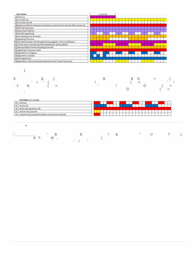
Call sequence
When the phone receives a call, it flashes red to indicate that a call is waiting for you to answer. Once you pick up the call, ittransitions to blinking blue, indicating that a call is in progress. If you place the call on hold, the LED continues to flash blue. If youadjust the volume of a call, the LED flashes orange once for each button press. If you mute the phone's microphone, the LEDtransitions to solid red until either the call disconnects or you un-mute the microphone. Once the call disconnects, the LED returnsto solid blue.
Phone Simulator - Simple but powerful tool that allows you to point to an IC Server and emulate a Polycom, Interaction SIP Station,or AudioCodes 420HD phone’s requests for configuration files. Also, the simulator performs all inheritance calculations anddisplays the result for all attributes in a searchable/filterable pane.
Phone Simulator
98

Troubleshooting (Interaction SIP Station I and II)Troubleshooting addresses two of the more common issues with the Interaction SIP Station I and II. Whenever troubleshooting anetwork issue with the Interaction SIP Station, packet captures are invaluable.
The Jabra GN 1200 headset supports a variety of telephones with different models requiring different switch settings. If you cannothear audio through the headset (for example, no ring tone when you press the volume up button), check the switch position on theinline switch on the headset. Interaction SIP Station I and II use switch position 1
If you specified incorrect network settings, such as an incorrect VLAN ID or static IP address settings, to a point to where theInteraction SIP Station unit can no longer start or connect to the network (as verified through packet captures), you can reset theunit to factory default network settings.
Warning!Only the network administrator should do this procedure, not an agent.
To reset Interaction SIP Station to factory default network settings1. Disconnect the network connection from the unit, which, in turn, removes power from the unit.2. Wait a few seconds.3. Do one of the following:
For Interaction SIP Station I, press and hold both round buttons on the top of the unit.For Interaction SIP Station II, press and hold the Mute and Volume down buttons.
4. Plug in the network connection into the unit. The unit restarts.5. Continue holding the two round buttons until the indicator light on the unit blinks three times with a purple color. The unit
resets to factory default network settings.
Cannot hear audio through headset
Interaction SIP Station cannot start or connect to the network
99

Boot and Provision Sequences (Interaction SIP Station I and II)Unlike a Polycom phone, the Interaction SIP Station I and II do not have separated boot and provision sequences. The unit powerson and then goes directly into the provisioning sequence.
Following is the firmware boot and provisioning sequence for SIP Station I and II:Phone powers on and does CDP and/or LLDP discovery, depending on configuration
Gets port-mode configurationGets VLAN information (if any)
Phone runs through DHCP discovery:DHCP must return:
IP AddressOption 1 - Subnet MaskOption 15 - DNS server
DHCP should return:Option 3 - Router to contact devices outside of subnetOption 66 - TFTP Server AddressOption 67 - Bootfile Name (usually sip100.img)Option 160 - Provision server address (usually the CIC server or a provisioning proxy)
DHCP may return:Option 4/42 - Network time serversOption 2 - Time offset
Phone queries DNS for the provision server found in Options 160If not found, the phone boots with its old configuration
Phone sends HTTP GET request for the Bootfile to the Provision ServerIt pulls a portion of the file and checks whether it matches its current firmwareIf it doesn't match, the phone GETS the complete file, flashes the firmware to its memory and reboots
Phone sends HTTP GET request for <MAC>.cfg to the Provision ServerPhone attempts to register with its configured SIP ProxyIf the configuration file changed, the phone reboots
A quick way to check what configuration passes to a phone is to use PhoneSim.exe, a PureConnect tool that simulates theprovisioning requests for managed IP phones. For more information, see "Phone simulator" in Boot and Provision Sequences(Polycom).
Firmware boot/provisioning sequence
Phone simulator
100

SIP Soft Phone Administration
SIP Soft Phone RequirementsCIC supports the SIP Soft Phone on workstations running on Microsoft Windows 7 (32-bit and 64-bit), Microsoft Windows 8 (32-bitand 64-bit), and Microsoft Windows 8.1(32-bit and 64-bit), which support the PureConnect QoS driver.
Notes:CIC doesn't support the SIP Soft Phone on workstations running Microsoft Windows XP (32-bit and 64-bit), which does notsupport the PureConnect QoS driver.CIC 2016 R2 and later supports Microsoft Windows 10.CIC 2015 R1 and later supports Microsoft Windows 8.1.CIC 2015 R1 and later no longer supports Microsoft Windows XP.
101

SIP Soft Phone InstallationThe SIP Soft Phone is a selectable feature on the Custom Setup page of the IC User Applications install (32-bit and 64-bit).
Ensure that you select this feature when installing IC User Applications on workstations that use the SIP Soft Phone. If not installedduring initial installation, click IC User Applications in the Control Panel -> Programs and Features, and then click Change to openthe Custom Setup page. Click the SIP Soft Phone feature.
On the QoS Requirement page, click PureConnect QoS driver to add the PureConnect certificate to the Trusted Publishers list andinstall the PureConnect QoS driver.
For more information:For instructions on installing IC User Applications, see the PureConnect Installation and Configuration Guide.For more information about the PureConnect QoS driver, see Implement QoS in Your Environment and the PureConnect KBarticle.
102

SIP Soft Phone Audio Device RequirementFor audio devices, audio quality and personal preference are subjective. When you select a USB headset, choose a quality headsetwith noise and echo cancellation. You can discuss personal experience with headsets and recommendations from other partnersand customers on the PureConnect Community Forum.
SIP Soft Phone Setup ProcessIf you followed the instructions to configure the network for SIP Soft Phones and to create multiple Managed IP Phones usingManaged IP Phones Assistant (with the full computer names filled in the CSV list), automated provisioning occurs when the SIP SoftPhone starts on a workstation.
Following are other required or recommended setup procedures, depending on the circumstances:If the workstation contains more than one NIC or if the NIC was altered following the SIP Soft Phone installation, specify thenetwork adapter to use with the SIP Soft Phone. For more information, see SIP Soft Phone Network Adapter Configuration andAuto-detection.Genesys highly recommends that SIP Soft Phone users configure their SIP Soft Phones to use the default devices configured inthe Windows Multimedia Control Panel. For more information, see SIP Soft Phone Audio Configuration.If you installed CIC Language Packs on the CIC system, SIP Soft Phone users can display the user interface in anotherlanguage. For more information, see Set the User Interface Language for SIP Soft Phone.If one of the following is true, you might need to provision the phones manually using the SIP Soft Phone Provisioning wizard:
There is no DHCP server.The system cannot access the DHCP server.You didn't specify the full computer name in the CSV list for some or all SIP Soft Phones.
For more information, see SIP Soft Phone Provisioning Wizard.
103

SIP Soft Phone Network Adapter Configuration and Auto-detectionIf the workstation contains more than one NIC or if the NIC was altered after the SIP Soft Phone installation, specify the networkadapter to use with the SIP Soft Phone after the phone is provisioned. You can configure the SIP Soft Phone to use a specificnetwork adapter for Real-time Transfer Protocol (RTP) and SIP communications.
To specify the network adapter1. Right-click the SIP Soft Phone icon in the system tray and then click Options.
2. In the Options dialog box, click the adapter that best suits the RTP or SIP traffic.
The SIP Soft Phone detects when a selected network adapter for SIP or audio connection is unavailable or disconnects; and thenterminates the connections. When the selected adapters are available again, the SIP Soft Phone establishes the connections again.
Auto-detection of changes to the network adapter
104

SIP Soft Phone Audio ConfigurationGenesys highly recommends that SIP Soft Phone users configure their SIP Soft Phone to Use default communication devices, whichis the default configuration set in the Windows Multimedia Control Panel.
To configure the audio device1. Right-click the SIP Soft Phone icon in the system tray and the click Options.
2. In the Options dialog box, click Audio Configuration.
3. Click Use default communication devices to use default configuration set in the Windows Multimedia Control Panel.The administrator needs to instruct users to configure the Windows Multimedia Control Panel to set the default speakers andmicrophone to a USB headset device:
a. Right-click the Speaker icon in the notifications area of the Windows taskbar and then click Sounds.b. Select and configure the headset's speaker on the Playback tab.c. Select and configure the headset's microphone device on the Recording tab.Alternatively, users can select Use custom settings on the Audio Configuration page to specify the speakers and microphoneto use.
105

Set the User Interface Language for SIP Soft PhoneIf you installed CIC Language Packs on the CIC system, SIP Soft Phone users can display the user interface in another language.
To configure the audio device1. Right-click the SIP Soft Phone icon in the system tray and then click Options.
2. In the Options dialog box, click Language.
3. In the Language list box, click the appropriate language for the user interface.4. Exit and restart the SIP Soft Phone.
SIP Soft Phone Provisioning WizardIf there is no DHCP server, the system cannot access the DHCP server, or you didn't specify the full computer name in the CSV listfor some or all SIP Soft Phones, provision the SIP soft phone using the SIP Soft Phone Provisioning wizard.
To provision SIP soft phones using the SIP Soft Phone Provisioning wizard1. Right-click the SIP Soft Phone icon in the system tray and then click Provision. The SIP Soft Phone Provisioning wizard
Welcome page appears.
106

2. Click Next. The Get SIP Soft Phone Configuration page appears. Specify how to load the phone configuration file. Theconfiguration file contains information to provision the SIP Soft Phone.
Automatic Discovery: If selected, the DHCP lookup provides the location of the provisioning server for you. If you configuredthe network for the SIP Soft Phone (DHCP Option 160), this option is selected by default. An information icon appears next tothis option. Rest the pointer on the icon to display either the reason the option is not available, or the location of theprovisioning server that the DHCP lookup provides.Configure Settings: If selected, displays the Phone Provisioning Server box to allow you to specify the provisioning server. Ifthe configuration file is not available or an error occurs during automatic discovery, you can select this option to loadconfiguration information manually.Phone Provisioning Server: Name of the phone provisioning server. If you select the Configure Settings option, this boxappears.
3. Do one of the following:
To load the configuration file automatically, do the following:
a. With the Automatic Discovery option selected, click Next.b. If there are any errors when loading the configuration, an error message appears on the Get SIP Soft Phone Configuration page.
Do one of the following:
If the configuration loads successfully and you have multiple network adapters, select the appropriate option on the SelectNetwork Adapters page.
107

If the configuration loads successfully and you do not have multiple network adapters, click Finish to exit the SIP Soft PhoneProvisioning wizard.
To load the configuration file manually, do the following:
a. Click Configure Settings.b. In the Phone Provisioning Server box, type the name of the provisioning server (CIC server).c. Click Next to load the specified configuration file.d. Do one of the following:
If the configuration loads successfully and you have multiple network adapters, select the appropriate option on theSelect Network Adapters page.If the configuration loads successfully and you do not have multiple network adapters, click Finish to exit the SIP SoftPhone Provisioning wizard.If the configuration file is not available on the server, click Next to complete the auto provisioning portion of the SIPSoft Phone Provisioning wizard.
4. If the Full Computer Name of the computer running the SIP Soft Phone does not match the Full Computer Name for any of theManaged IP Phones configured in the Managed IP Phones container in Interaction Administrator, the Use Auto Provisioningpage appears.
This page allows you to provision the SIP Soft Phone using the provisioning IVR. The wizard initiates a call to the CIC serverto do the provisioning. The server then generates the appropriate configuration and triggers the SIP Soft Phone to retrieveits new configuration.
5. If the Use Auto Provisioning page appears, do the following:a. Click Provision.
Note:If the Provision button is not available, see Troubleshooting (SIP Soft Phone).
b. Following the voice prompts, provide the requested information using the dial pad. For example, the type of provisioning (byadministrator or user), the extension number for the phone, and the PIN number. Administrators need to specify bothadministrator and station information.The CIC server generates the appropriate configuration and triggers the SIP Soft Phone to retrieve its new configuration.
c. After provisioning the SIP Soft Phone, click Next.
The SIP Soft Phone Provision Complete page appears whenever SIP Soft Phone provisioning is complete, depending on theoption used for loading the configuration file and whether provisioning was necessary.
6. Click Finish.
SIP Soft Phone HelpFor instructions on using the SIP Soft Phone, see the SIP Soft Phone documentation.
108

Managed IP Phone (SIP Soft Phone) Configuration OptionsThe managed IP phone options reflect the state of SIP Soft Phone configuration as of CIC 4.0 GA.
These configuration options are available from the Managed IP Phones container when editing one or more managed SIP SoftPhones. This tab allows for configuration of diagnostic captures and emergency information, among other options. For moreinformation about these options, see the Interaction Administrator Help.
Options tab
109
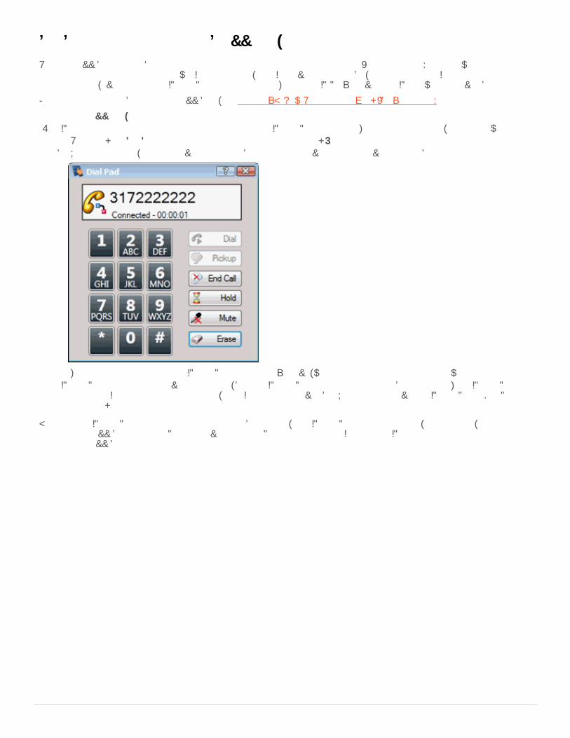
SIP Soft Phone and Remote SurvivabilityRemote survivability is the ability of a remote location to continue to operate in some (typically limited) capacity when theconnection to the main location is down. In this scenario, the CIC server is unreachable, meaning that the CIC client applicationcannot function, even though the SIP Soft Phone is still running. The local SIP Proxy server and SIP gateways are available also.
For more information about remote survivability, see Appendix B: How Registrations Work (Proxy Settings).
In a remote survivability scenario1. SIP Soft phone users can place outbound calls using the SIP Soft Phone dial pad. To access the dial pad, do the following:
a. Right-click the SIP Soft Phone icon in the system tray and then click Dial Pad.b. Using the dial pad, you can provide phone numbers to dial and have call control over those outbound calls.
The calls go directly from the SIP Soft Phone to the proxy server, which routes them out the local gateway.2. SIP Soft Phone users can receive inbound calls, but the SIP Soft Phone cannot alert users about the calls. The SIP Soft Phone
relies on the CIC client for this functionality, and CIC client is not available. Users need to have the SIP Soft Phone Dial Padopen to check for calls.
Because the SIP Soft Phone does not alert or pop for inbound calls, the SIP Soft Phone is not practical, and therefore, not supportedas a remote survivability solution. Physical devices such as Polycom phones and Interaction SIP Station phones are more practicalin a remote survivability situation.
110

Troubleshooting (SIP Soft Phone)Troubleshooting addresses a few of the more common problem scenarios encountered with SIP Soft Phones. In these scenarios, itis useful to obtain a packet capture to see exactly what traffic is passing to and from the SIP Soft Phone, including DNS and SIPtraffic.
The SIP Soft Phone uses DHCP Option 160, which it queries from the DHCP server to obtain the name of the provisioning server.There are a few reasons why the SIP Soft Phone cannot obtain the configuration file from provisioning server.
Note:Obtaining a packet capture from both the client and server may be a necessary troubleshooting step.
To ensure that the SIP Soft Phone can obtain configuration from provisioning server1. Verify DHCP Option 160 configuration on the DHCP server. (For more information, see Configure DHCP Option Records.)2. Verify through DNS that the hostname configured in DHCP resolves to the IP address of the correct CIC server. (For more
information, see Configure DHCP Option Records.)3. Verify that the Windows User account that is running the SIP Soft Phone has full access to the following registry keys:
HKLMSoftwarePoliciesMicrosoftSystemCertificatesHKLMSoftwarePoliciesMicrosoftCryptography
4. Verify that the Windows User account that is running the SIP Soft Phone has full access to the following file path:
%ALLUSERSPROFILE%\Application Data\Microsoft\Crypto\Keys
5. If there is a firewall between the client workstation running the SIP Soft Phone and the CIC servers, verify that the firewall rulesallow communication to the CIC servers on ports 8088 (http) and 8089 (https).
If the SIP Soft Phone cannot place calls, it typically indicates that it is not registered and results in the following behavior:Placing outbound calls using the CIC client doesn't complete.The CIC client cannot pick up incoming calls.
Note:Obtaining a packet capture from both the client and server is a helpful troubleshooting step.
To ensure that the SIP Soft Phone can register1. Ensure that the appropriate network adapter and VPN are selected on the Options page. For more information, see SIP Soft
Phone Requirements.2. Ensure that the audio device is working properly by running the Audio Tuning Wizard in Interaction Desktop. For more
information, see Audio Tuning Wizard.3. Ensure that the SIP Soft Phone can resolve the name of its proxies correctly (through DNS). (For more information, see
Appendix B: How Registrations Work (Proxy Settings).Verify that the SIP Soft Phone resolves the applicable DNS record correctly (for example, DNS SRV, server hostname, SIP Proxyname).
Startup and Provision Sequences (SIP Soft Phone)The behavior of a SIP Soft Phone upon powering on is helpful while troubleshooting a phone to understand what it is doing duringstartup.
Startup sequenceThere are two ways to start the SIP Soft Phone. You can start the SIP Soft Phone by manually running it from the desktop shortcut;
SIP Soft Phone cannot obtain configuration from provisioning server
SIP Soft Phone contacts provisioning server but cannot register
111

or by attempting to log on to CIC client and then selecting SIP Soft Phone as the station type. (Only a single instance of the SIP SoftPhone can run at a time.) In either case, the startup sequence is the same.
In the startup sequence, the SIP Soft Phone attempts to:Initialize the audio input and output devices based on registry keys:
HKEY_CURRENT_USER\ Software\ Interactive Intelligence\ SIP Soft Phone\ <fullcomputername>\ 4.0 Selected Audio Input Device
HKEY_CURRENT_USER\ Software\ Interactive Intelligence\ SIP Soft Phone\ <fullcomputername>\ 4.0 Selected Audio Output Device
Bind to the network adapter based on a registry key:
HKEY_CURRENT_USER\ Software\ Interactive Intelligence\ SIP Soft Phone\ <fullcomputername>\ 4.0 Selected Network Adapters
Download a configuration file based on a registry key:
HKEY_CURRENT_USER\ Software\ Interactive Intelligence\ SIP Soft Phone\ <fullcomputername>\ 4.0 ConfigUrl
If the previous step fails, the SIP Soft Phone attempts to download a configuration file based on a DHCP Option 160.
If the SIP Soft Phone provisioned successfully during a previous startup, it looks in the registry first for a key that specifies theconfiguration file.
HKEY_CURRENT_USER\ Software\ Interactive Intelligence\ SIP Soft Phone\ <fullcomputername>\ ConfigUrl
(for example, https://provision.lab.voip:8088/AgentPC1.lab.local.i3sipcfg)If the configuration file registry key does not exist, the SIP Soft Phone queries the DHCP server for Option 160 to determinewhether a boot server definition exists and then attempts to download the configuration file.If that option does not define a boot server, you need to provision the SIP Soft Phone manually using the SIP Soft PhoneProvisioning wizard.
A quick way to check what configuration passes to a phone is to use PhoneSim.exe, a PureConnect tool that simulates theprovisioning requests for managed IP phones. For more information, see "Phone simulator" in Boot and Provision Sequences
Provision sequence
Phone simulator
112

(Polycom).
113
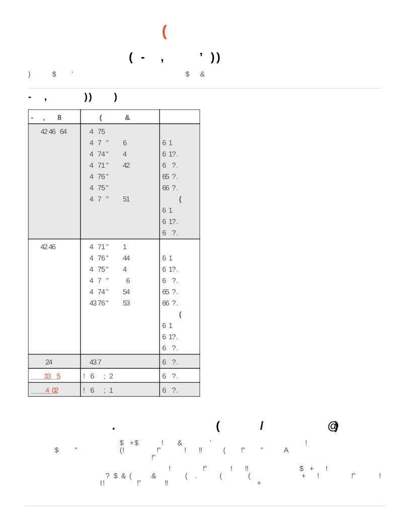
AudioCodes and Genesys Phone Administration
AudioCodes and Genesys Firmware for Supported PhonesThe following table lists the AudioCodes and Genesys firmware versions for supported phones.
Firmware Version Initially Made Available in... Phone Model
2.2.16.142.41 2019 R3
2019 R2 Patch 4
2019 R1 Patch 10
2018 R5 Patch 16
2018 R4 Patch 22
2018 R3 Patch 29
2018 R2 Patch 35
AudioCodes
405
405HD
420HD
430HD
440HD
Genesys
405
405HD
420HD
2.2.16.142 2018 R5 Patch 5
2018 R4 Patch 11
2018 R3 Patch 18
2018 R2 Patch 24
2018 R1 Patch 31
2017 R4 Patch 37
AudioCodes
405
405HD
420HD
430HD
440HD
Genesys
405
405HD
420HD
2.2.8.61 2017 R2 420HD
2.2.277.2.3 IC 4.0 SU 6 420HD
2.0.0.18_6 IC 4.0 SU 5 420HD
Managed IP Phone (AudioCodes and Genesys Phones) Configuration OptionsAudioCodes and Genesys phones work with the CIC provisioning subsystem and you configure them in Interaction Administrator inthe same way as Polycom phones, Interaction SIP Station I and II phones, and SIP Soft Phones. You must implement eachAudioCodes or Genesys phone as a managed IP phone.
AudioCodes and Genesys phones are similar to the Interaction SIP Station I and II phones in their network and InteractionAdministrator configuration. However, they have a headset, LCD display, a dial pad, and more function keys. Interaction SIP Station Ihas none of these features; Interaction SIP Station II has a dialpad and more function keys only.
Firmware for supported phones
114
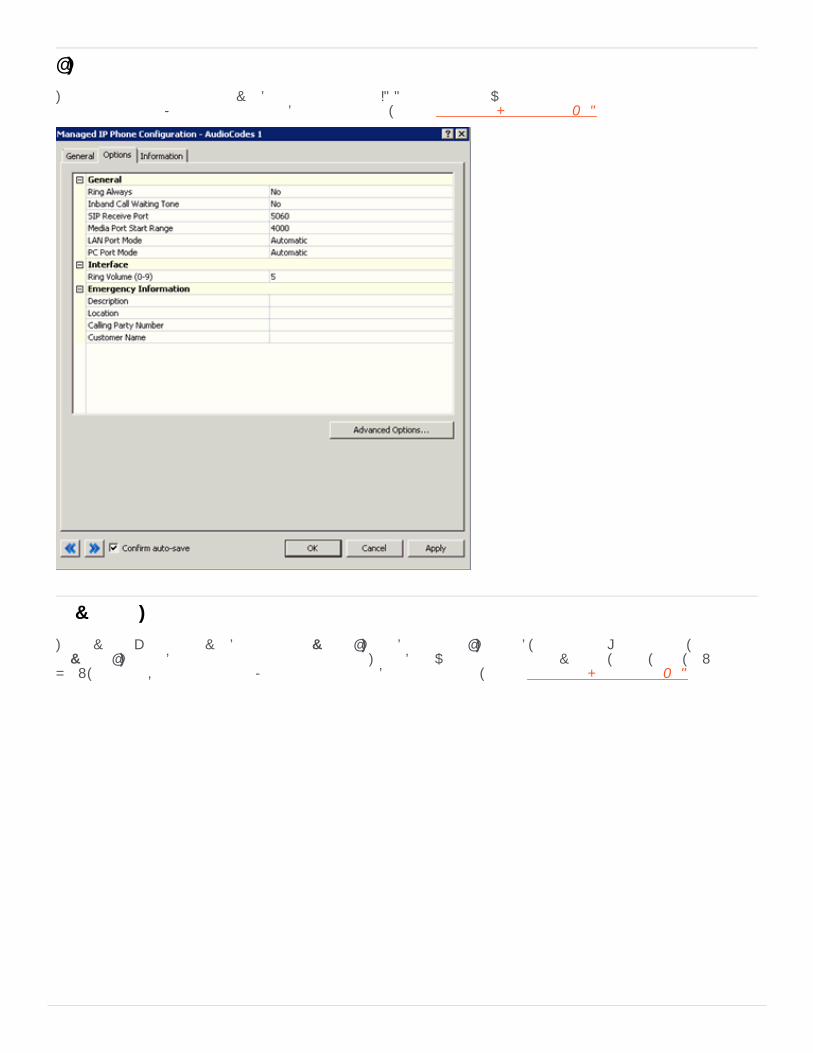
These configuration options are available from the Managed IP Phones container when editing one or more managed AudioCodesor Genesys phones. For more information about these options, see the Interaction Administrator Help.
The Advanced Options are available from the Advanced Options button in the Options tab, if configuring just one phone, or in theAdvanced Options tab if configuring more than one phone. This tab allows configuration of provisioning, syslog, gains, LAN andVLAN, and audio quality diagnostics. For more information about these options, see the Interaction Administrator Help.
Options tab
Advanced options
115
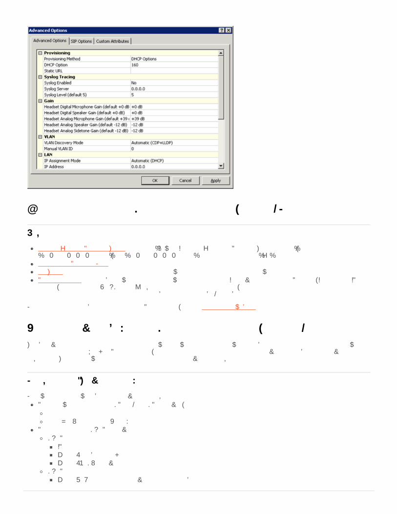
Other Managed IP Phone (AudioCodes and Genesys Phone) Features
Customizing Call Progress Tones - Contains "How do I customize my Call Progress Tones file.doc","usa_tones_09_no_hold.dat", and "usa_tones_09_no_hold.ini". See instructions in the ".zip" file.Sample Call Progress Files - Contains sample files and instructions.AC Tools - Contains instructions and a utility to allow logging on the AudioCodes gateway.Phone Simulator - Simple but powerful tool that allows you to point to an IC Server and emulate a Polycom, Interaction SIPStation, or AudioCodes 420HD phone’s requests for configuration files. Also, the simulator performs all inheritancecalculations and displays the result for all attributes in a searchable/filterable pane.
For more information about the AudioCodes Phone Series, see the AudioCodes website.
Boot and Provision Sequences (AudioCodes and Genesys Phones)The behavior of AudioCodes and Genesys phones when powering on is helpful while troubleshooting a phone to understand what itis doing during startup. Unlike a Polycom phone, AudioCodes and Genesys phones do not have separate boot and provisionsequences. The units power on and then go directly into the provisioning sequence.
Following is the firmware boot and provisioning sequence for AudioCodes and Genesys phones:Phone powers on and does CDP and/or LLDP discovery, depending upon configuratio
Gets port-mode configurationGets VLAN information (if any)
Phone runs through DHCP discoveryDHCP must return:
IP AddressOption 1 - Subnet MaskOption 15 - DNS server
DHCP should return:Option 3 - Router to contact devices outside of subnet
Download files
Firmware boot/provisioning sequence
116

Option 66 - TFTP Server AddressOption 67 - Bootfile Name (usually 420HD.img)Option 160 - Provision server address (usually the CIC server or a provisioning proxy)
DHCP may return:Option 4/42 - Network time serversOption 2 - Time offset
Phone queries DNS for the provision server found in Option 160If not found, the phone boots with its old configuration
Phone sends HTTP GET request for the Bootfile to the Provision ServeIt pulls a portion of the file and checks whether it matches its current firmwareIf it doesn't match, the phone GETS the complete file, flashes the firmware to its memory, and then reboots
Phone sends HTTP GET request for other config files listed with the CUSTOM::config_files attribute specifiedPhone sends HTTP GET request for <MAC>.cfg to the Provision ServePhone attempts to register with its configured SIP proxIf the configuration file changed, the phone reboot
The provisioning server supports the ability to add a custom attribute to AudioCodes and Genesys phones named config_files(case-insensitive), which must contain a comma-separated list of files. If the file exists in the \i3\ic\provision\AudioCodesdirectory on the CIC server, provisioning includes the files in the config_files list for AudioCodes phones. If the file exists in the\i3\ic\provision\Genesys directory on the CIC server, provisioning includes the files in the config_files list for Genesysphones.
The system requests these files after provisioning generates the config files and allows administrators to set custom config fileattributes that provisioning doesn't handle.
Following is the format of the custom configuration files.
The Configuration file is a *.cfg file with the file name specified in the list under the config_files custom attribute.
Ensure that the configuration file adheres to the following guidelines:No spaces on either side of the equals (=) sign.Each parameter is on a new line.Each parameter has the following syntax: <parameter name>= <value>
Following is an example of part of a configuration file:
voip/line/0/enabled=1voip/line/0/id=1234voip/line/0/description=310HDvoip/line/0/auth_name=1234voip/line/0/auth_password=4321
A quick way to check what configuration passes to a phone is to use PhoneSim.exe, a PureConnect tool that simulates theprovisioning requests for managed IP phones. For more information, see "Phone simulator" in Boot and Provision Sequences(Polycom).
AudioCodes DocumentationGateway Backup and Restore - How to backup and restore your gateway's ini file
Configure Audiocodes Gateway Setup - How to set up AudioCodes Gateway with 7.2+ firmware
Configure AudioCodes FXS and FX0 Gateway - How to configure AudioCodes FXS and FXO Gateway with 6.0+ firmware
Configure AudioCodes Mediant 1000 or 2000 - How to configure the Mediant 1000 or 2000 Gateway
Custom configuration files
Phone simulator
117

Appendixes
Appendix A: Non-standard Provisioning ScenariosThis appendix describes several non-standard provisioning scenarios when there is no DHCP server or the system cannot accessthe DHCP server.
If you deploy a managed IP phone at a remote site, it is possible to avoid excess WAN traffic associated to provision phones. TheInteraction SIP Proxy offers a Provision Proxy feature when using CIC to manage it. Phones can send their HTTP provisioningrequests to the SIP Proxy, instead of over the WAN to the CIC server.
When an HTTP request comes in from a phone, the SIP Proxy forwards the HTTP requests to the CIC server and then cacheswhatever the Provision Server returns. The next time a request comes in for the same file, the SIP Proxy checks with the ProvisionServer to see whether the file changed, and then returns the file to the phone.
You enable the Provision Proxy feature from the System -> CIC Integration tab in the SIP Proxy web interface.
On a Polycom phone, follow these steps to point the phone to the CIC (boot) server. As needed, use the buttons and arrow keysnext to the choices displayed on the phone's LCD screen.
Note:Steps for some phones differ slightly from those described here, and steps often differ depending on whether a phone is juststarting or running already. If these steps don't match your phone, see the Polycom documentation for instructions about howto configure your phone.
To configure a Polycom phone's boot server1. On the phone's Network Configuration screen, do the following:
a. Press the Menu button, press 3 for Settings, and then press 2 for Advanced.b. Key in the password (the default is 456) and then press the Enter button.c. Press 1 for Admin Settings and then press 1 for Network Configuration.
2. On the screen where you specify the CIC server's address, do the following:a. Choose DHCP Menu and then press Select.b. Choose Boot Server and then press Edit.c. Use the arrow keys to select Static.d. Press OK and then press Exit to go up a level.e. Use the arrow keys to select ServerMenu and then press Select.f. Select ServerType:, use the arrow to select HTTP, and then press OK.g. Select ServerAddr: and then press Edit.
Remote phones
Configure a Polycom phone's boot server manually
118
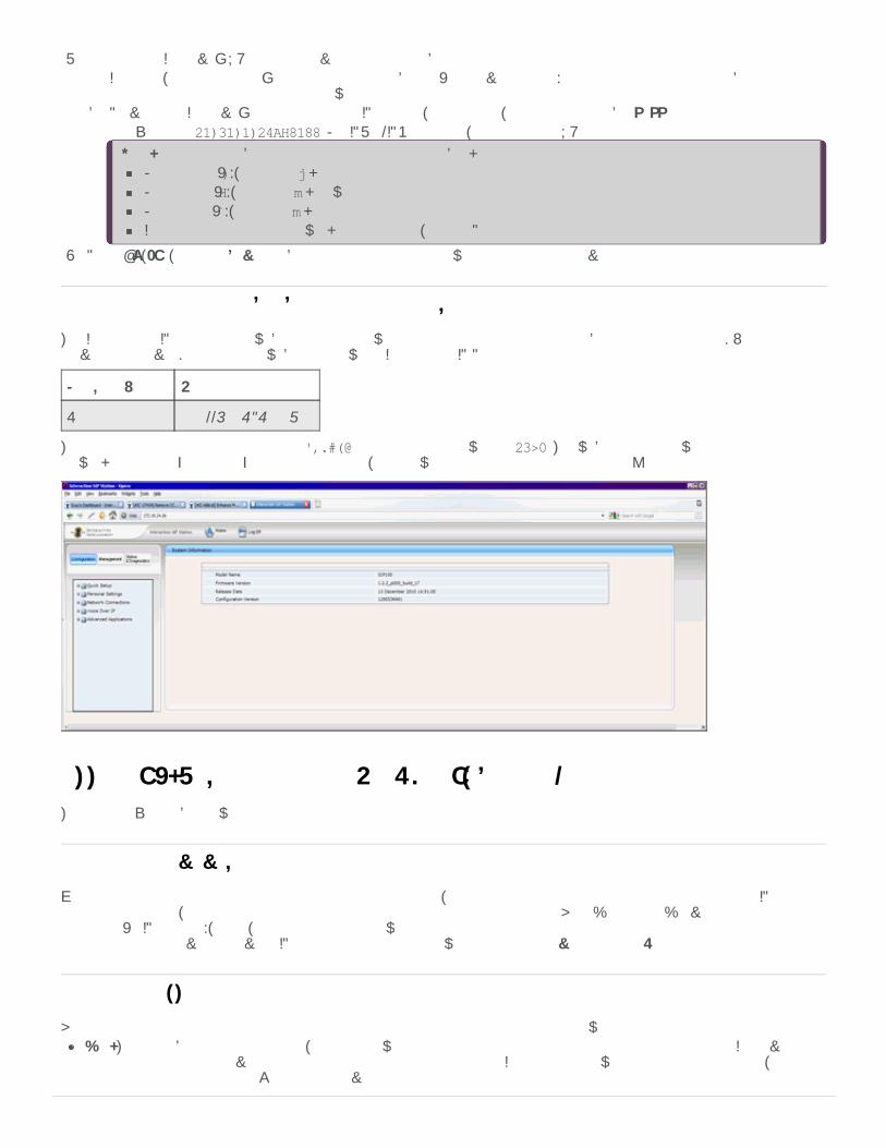
3. Specify the CIC server's URL and the provisioning port number:a. If needed, press the phone's Alphanumeric toggle button (see previous image) to toggle from letters to numbers. Some
phones differ slightly from the one shown here.b. Provide the CIC server's computer name or IP address, then a colon, and then port number 8088.
An example is 10.20.0.157:8088. For IP300/IP500 models, specify the full URL.
Note: Specify letters by pressing the corresponding number key multiple times:For a period (.), press the * key once.For a colon (:), press the # key twice.For a slash (/), press the # key three times.If these instructions do not work on your phone, see the Polycom documentation for your phone.
4. Press OK, Exit, and then Save to reboot the phone and connect with the designated server.
The Interaction SIP Station has a web interface to allow configuration in the instance of inability to connect to the DNS or aprovisioning server. Do not use the web interface with CIC Managed IP Phones.
Firmware Version Web Interface Address
1.2.2 http://<ISS_ip_addr>:80
The default user name for the interface is admin and the default password is 1234. The web interface allows for configuration ofnetwork parameters; speed dial; and diagnostic tools, and allows for manual updating of the phone’s configuration.
Appendix B: How Registrations Work (Proxy Settings)This appendix describes how registration groups function.
When you configure a phone to use a particular registration group, all station appearances on that phone use the same SIPregistration settings, according to the contents and ordering of the registration group. Each "registration" serves as a mapping to ahostname (or IP address), a port, and a protocol for use when the phone registers. Configuring more than one registration in aregistration group serves to provide SIP redundancy according to two paradigms: failover and fallback.
Each registration group consists of an ordered list of one or more registrations of the following types:Line: The most basic registration type, the Line allows for selection of a line that you defined for the particular CIC server. Allthe transport settings derive from the configuration of the selected line. If there is a Line within the registration group, ensurethat the Line is the first entry. You can only have one Line per registration group.
Configure an Interaction SIP Station through the web interface
Registrations overview
Registration types
119

Manual: Manual registrations allow for administrator-specified registrations. You must specify the address, port, and transportprotocol. The address is either a hostname, FQDN, or IP address. It can point to anything, but use caution. Customers usedmanual registrations for secondary SIP proxies, primarily, but with the ability to use a Managed Proxy, the use of manualregistrations declined.Managed Proxy: The Managed Proxy feature of the Interaction SIP Proxy allows phones in a remote location to register with theSIP proxy while maintaining some functionality of, and communication with, the CIC server. You must specify the transportprotocol, but the system derives the contact address and port from the configuration of the associated Managed Proxy. Tofunction properly, ensure that the managed phone and its Managed Proxy are in the same CIC location. Customers useManaged Proxies for remote survivability situations. For more information, see Remote survivability (fallback).DNS SRV: The DNS SRV records are a way for the phone to track multiple registration addresses without CIC needing to do italso. It's common for customers to use this registration type in Switchover settings. For more information, see Switchover(failover).
Switchover operates according to the failover paradigm: the primary registration is actually a pair of CIC servers (a Switchover pair)in which both servers have the same capabilities. When an agent places a call, the phone attempts to contact the last knownfunctional server. If the active server fails, the other server in the pair comes up. When an agent places another call, the phoneattempts to contact the "down" server first, and then contacts the "up" server when the previous attempt fails. For each subsequentcall, the phone remembers which server was functional last and routes its call attempts accordingly.
For Polycom phones and for SIP Soft Phones, you configure this option through a DNS SRV registration in the registration group.Since the DNS SRV record can point to more than one registration address, the phones can track both members of the Switchoverpair without CIC needing to notify them of a Switchover event.
Remote survivability is the ability of a phone to maintain a SIP registration when a connection to the main CIC server severs.Remote survivability operates according to the fallback paradigm: there is a single main registration and one or more limited-functionality registrations. The system treats any other registration entries in a registration group as such and assumes them tohave less than the full CIC functionality.
When connection to the main CIC server severs, the phones try each of the fallback registrations successively whenever an agentplaces an outbound call.
Following is a common scenario for remote survivability:
Your implementation has a distributed architecture where remote offices only have phones; proxy servers; and SIP gateways, andconnect to the CIC servers at a central location through MPLS/WAN connections. If the WAN fails, the phone attempts to contactthe CIC server first. If that fails, the phone calls through the Proxy, which routes the call out the local SIP gateway.
For Polycom phones only, external registrations allow a specific line/station appearance on a phone to register differently than allthe other lines on that phone. For example, external registrations are useful in a large company where CIC deploys for a certainsector like customer support, and some other SIP call system deploys elsewhere. If an employee needs to call into the other SIPcall system directly, you can add an external registration to that user's phone.
There are two parts to setting up external registrations:Set up the external registration groupAdd the external registration to the phone
Set up the external registration group
To designate a registration group as external, select a registration group type of External rather than Regular when creating theregistration group. The registration group itself is then much like a regular registration group, with the exception that the onlyregistration types allowed are Manual and DNS SRV. As before, there is no limit on the number of entries the group, but more thanthree is impractical.
Once created, you can only use the external registration group for external registrations. It is not available for selection as the mainRegistration Group of a managed IP phone.
Add the external registration to the phone
Switchover (failover)
Remote survivability (fallback)
External registrations (proxy settings)
120

After creating an external registration group, you can add external registrations to Polycom managed IP phones in a similar mannerto adding a shared station appearance. Configure the station with whatever Identification Address and credentials that the SIPserver in the corresponding external registration group expects.
121

Change LogThe following table list the changes to the CIC Managed IP Phones Administrator's Guide since its initial publication.
Date Changes
01-June-2012 In Chapter 3: "Create individual managed IP phones for test purposes":Updated "Registration group configuration" for default protocol changed from TCP to UDP in IC 4.0SU1.Updated "Polycom and SIP Soft Phone registration group configuration" to add screenshot to"Switchover settings".
Updated Chapter 6: "Additional Configuration (Polycom)" to add "SpectraLink Wi-Fi phoneconsiderations" subsection to "Polycom firmware and model limitations".Updated Chapter 7: "Troubleshooting (Polycom)" under "Polycom phone cannot locate boot server",added note about SpectraLink phones.
11-January-2013 In Chapter 14: "Setup and Configuration (SIP Soft Phone)," revised "Audio device requirement" statement.
24-January-2013 In Chapter 1: "Introduction to IC Managed IP Phones," updated "About this guide" to refer to the ICMigration Guide for the procedures for migrating IC 3.0 managed IP phones to IC 4.0 managed IPphones.In Chapter 3: "Create individual managed IP phones for test purposes", updated the screenshots in"Create individual managed IP phones for test purposes" procedure to include the selectable firmwareversion option on the Managed IP Phone Configuration – General tab, added in IC 4.0 SU 3.In Chapter 6: "Additional Configuration (Polycom)", renamed the subsection on Polycom firmware to"Polycom firmware and phones (IC 4.0 SU 3 and later)" and updated it for the selectable firmware versionfeature and other firmware changes in IC 4.0 SU 3.
25-July-2013 In Chapter 3: "Create individual managed IP phones for test purposes", added note in the "Default registrationgroup" subsection that a registration group cannot have more than one SIP line or DNS SRV registration.
30-October-2013 In Chapter 6: "Additional Configuration (Polycom)", updated the "Polycom firmware for supported andEOL phones" section for firmware supported in IC 4.0 SU 3 and later.In Chapter 2: "Configure the network for managed IP phones", in "Required DHCP option provisioningrecords", updated Option 132 for Interaction SIP Station.Updated the following sections for Interaction SIP Station support for DNS SRV in IC 4.0 SU 4 and later:
Chapter 2: "Configure the network for managed IP phones", sections "IP phone network configurationtask list" and "Create DNS service location (SRV) records for Switchover".Chapter 3: "Create individual managed IP phones for test purposes", section "Interaction SIP Stationregistration group configuration".Appendix B: How registrations work (proxy settings).
13-January-2014 In Chapter 6: "Additional Configuration (Polycom)", added entry Polycom firmware for VVX600 phones in"Polycom firmware and phones (IC 4.0 SU 3 and later)", to be available in IC 4. SU 5 and pre-release supportavailable in IC 4.0 SU 3 and IC 4.0 SU 4.
27-January-2014 In Chapter 6: "Additional Configuration (Polycom)":Modified table in "Polycom firmware and phones (IC 4.0 SU 3 and later)" to show official support inIC 4.0 SU 5 for VVX300, 310, 400, 410, and 600 phones.Added new section "Interaction Firmware" for IC 4.0 SU 5 and later.
In Chapter 11: "Additional Configuration (Interaction SIP Station)", added new section "InteractionFirmware" for IC 4.0 SU 5 and later.Updated guide for support for AudioCodes 420HD IP phone in IC 4.0 SU 5 and later. Created new"AudioCodes Administration" section.
16-May-2014 In Chapter 6: "Additional Configuration (Polycom)", modified table in "Polycom firmware and phones (IC 4.0SU 6 and later)":
To show official support in IC 4.0 SU 6 for Polycom firmware 4.1.6hAdd "IC Release" column showing what SUs and ESs a firmware version is supported in.
122

15-September-2014 Updated documentation to reflect changes required in the transition from version 4.0 SU# to CIC 2015 R1,such as updates to product version numbers, system requirements, installation procedures, and copyrightand trademark information.
05-December-2014 Made updates throughout the entire document for Interaction SIP Station II and associated firmware,available in CIC 2015 R2 and later.In Chapter 2: "Configure the network for managed IP phones," made the following updates:
Added new section "Configure DHCP records for multiple phone models."In "Configure the TFTP server," removed section on manually copying the firmware file to the TFTPserver for a Switchover pair, as this has been fixed for CIC 2015 R2 and later.
17-June-2015 In Chapter 6: "Additional Configuration (Polycom)," updated "Polycom firmware and phones (CIC 4.0 SU 6,CIC 2015 R4 and later)" for new Polycom SoundPoint IP and VVX firmware in CIC 2015 R4.
01-July-2015 In Chapter 14: "Setup and configuration (SIP Soft Phone)," updated "SIP Soft Phone requirements" to includesupport for 32-bit as well as 64-bit for Windows 8 and Windows 8.1.
15-September-2015 Updated document to reflect transition to Interaction Desktop in CIC 2015 R3 and removal of InteractionClient .NET Edition in CIC 2016 R1.Updated document for rebranding in CIC 2016 R1.
15-October-2015 In Chapter 2: "Configure the network for managed IP phones," in the "Required DHCP option provisioningrecords" table, updated Option 067 to provide more information and refer to the "Configure DHCP records formultiple phone recovery" section.
15-February-2016 In Chapter 6: "Additional Configuration (Polycom)," updated "Polycom firmware for currently supportedphones table" to remove older, obsolete firmware versions.Updated the copyright page.
10-April-2016 In Chapter 6: "Additional Configuration (Polycom)," updated "Polycom firmware for currently supportedphones table" for support for VVX 100 and 200 phones in CIC 2016 R4 and later.Updated the following chapters for TLS/SRTP support for Interaction SIP Station and AudioCodes in CIC2016 R4 and later:
Chapter 1: "Introduction to IC Managed IP Phones", updated "Managed IP phones and SIP security."Chapter 3: "Create individual managed IP phones for test purposes", updated the following sections:
"Create individual managed IP phones for test purposes" – Audio Protocol field"Registration group configuration"
In Chapter 14: "Setup and configuration (SIP Soft Phone)," updated "SIP Soft Phone requirements" toinclude support for Windows 10 in CIC 2016 R2 and later.
21-June-2016 In Chapter 6: "Additional Configuration (Polycom)," updated "Polycom firmware for currently supportedphones table" to update firmware versions.
02-August-2016 In Chapter 6: "Additional Configuration (Polycom)," updated "Polycom firmware for currently supportedphones table" to include new VVX models 301, 311, 401, 411, 501, 601.
26-September-2016 In Chapter 6: "Additional Configuration (Polycom)," updated "Polycom firmware for currently supportedphones table" to update firmware versions.
26-October-2016 In Chapter 6: "Additional Configuration (Polycom)," updated "Polycom firmware for currently supportedphones table" to update firmware versions to remove 5.4.0a and replace 5.4.3.1014 with 5.4.3.2036 andreplace 4.0.8.1972.H with 4.0.8.2058.I.
07-March-2017 Added note to "Polycom boot Sequence" topic to mention advanced options for boot sequence.Added note to "Limitations" section to indicate that starting with CIC 2016 R1, firmware updates with aversion of 2.2.2.77 or higher for Interaction SIP Station I & II remove the constraint of registering thephone with a single server.
28-April-2017 In Chapter 6: "Additional Configuration (Polycom)," updated "Polycom firmware for currently supportedphones table" to include firmware 5.4.5G.
19-September-2017 Rebranded to Genesys.
20-March-2018 Updated document format and removed chapter numbers.
123
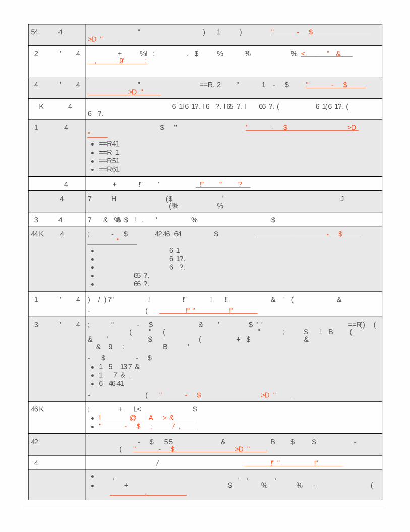
31-May-2018 Added support for Polycom phone models Trio8500 and Trio8800 in Polycom Firmware for Supported andEOL Phones.
06-September-2018 Added a link to the "CIC Utilities and Downloads" page for "Phone Simulator" in Boot and ProvisionSequences (Polycom).
21-September-2018 Added support for Polycom phone model VVX D60 and Polycom 5.8. Firmware in Polycom Firmware forSupported and EOL Phones.
08-January-2019 Added support for AudioCodes 405; 405HD; 420HD; 430HD; and 440HD, and Genesys 405, 405HD, and420HD.
05-March-2019 Added support for the following Polycom phone models in Polycom Firmware for Supported and EOLPhones:
VVX 150VVX 250VVX 350VVX 450
29-March-2019 Added link to the SIP Soft Phone help in SIP Soft Phone Help.
29-April-2019 Reorganized the content only, which included combining some topics and deleting others that just had anintroductory sentence such as, "In this section...".
07-May-2019 Removed "New CIC Distribution Model" as the model is no longer new.
11-June-2019 Updated Firmware to 2.2.16.142.41 for the following phones in AudioCodes and Genesys Firmware forSupported Phones:
AudioCodes and Genesys 405AudioCodes and Genesys 405HDAudioCodes and Genesys 420HDAudioCodes 430HDAudioCodes 440HD
25-September-2019 TLS/STRP support for Interaction SIP Station I and II phones is not available, as indicated previously.
For more information, see Managed IP Phones and SIP Security.
27-September-2019 Updated Polycom Firmware to address a vulnerability in the web-based management interface of VVX, Trio,SoundStructure, SoundPoint, and SoundStation phones running Polycom UC Software. If exploited, thevulnerability could allow an authenticated, remote attacker with administrator privileges to cause a denial ofservice (DoS) condition or execute arbitrary code.
Following are the Firmware updates:5.9.3.2857 Rev G5.9.0 Rev AD4.0.14.1580
For more information, see Polycom Firmware for Supported and EOL Phones.
14-January-2020 Updated links to KB articles in the following:Implement QoS in Your EnvironmentPolycom Firmware Update Required
16-March-2020 Added support for Firmware 3.3.2 and added a server parameter to fix a firmware downgrade issue. For moreinformation, see Polycom Firmware for Supported and EOL Phones.
01-April-2020 Changed path to Security Features Technical Reference in Managed IP Phones and SIP Security.
29-April-2020 Update or remove links to "my.inin.com" as appropriate.Added links to AudioCodes documentation that were on the "my.inin.com" site. For more information,see AudioCodes Documentation.
124