CHRYSLER LLC 101... · 3.7 GE Solutions (formerly IRI) 3.8 ... filters in a metal frame. Filters...
54
CHRYSLER LLC Chrysler Security Services Fire Protection Engineering Standards Standard 101 Painting and Powder Coating Issued: 9/93 Revised: 3/01 12/01 11/02 01/03 05/03 09/03 04/04 11/05 2/06 3/06 06/06 09/07 02/09 09/09 02/10 11/10 2/11 3/11 5/11 6/11 8/11 9/11 03/12 5/12 6/12 11/12, 02/13
Transcript of CHRYSLER LLC 101... · 3.7 GE Solutions (formerly IRI) 3.8 ... filters in a metal frame. Filters...
- 1 -1
CHRYSLER LLC
Chrysler Security Services
Fire Protection Engineering Standards
Standard 101
Painting and Powder Coating
Issued: 9/93 Revised: 3/01 12/01 11/02 01/03 05/03 09/03 04/04 11/05 2/06 3/06 06/06
09/07 02/09 09/09 02/10 11/10 2/11 3/11 5/11 6/11 8/11 9/11 03/12 5/12 6/12 11/12, 02/13
Standard 101 2
Table of Contents
1.0 Introduction
1.1 Purpose
1.2 User
1.3 Authorization
2.0 Definitions
2.1 General
3.0 References
3.1 General
3.2 National Fire Protection Association Standards and Factory Mutual Data Sheets
3.3 Industrial Fire Hazards Handbook
3.4 Fire Protection Handbook
3.5 Underwriters Laboratories
3.6 Factory Mutual Global
3.7 GE Solutions (formerly IRI)
3.8 Canadian Standards/Codes
3.9 Building Codes
4.0 General
4.1 Equipment
4.2 Approvals
4.3 Testing/Startup Assistance/Training
4.4 Proprietary Products
4.5 Planned Hot Work
4.6 Emergency Repair Work
5.0 Extinguishing Systems
5.1 Sprinkler Systems
5.1.1 General
5.1.2 Materials
5.1.3 Design Densities
5.1.4 Sprinkler Heads
5.1.5 Exhaust Ducts/Stacks
5.1.6 Waterflow Supervision
5.2 Fire Hose Stations
5.3 Portable Fire Extinguishers
5.4 Special Systems
5.4.1 General
5.4.2 Gaseous Agents in Paint Booths and Associated Spraying Equipment
5.4.3 Gaseous Agents in Hazardous Rooms including High Value Rooms
Standard 101 3
5.4.4 High Speed Water Spray (Deluge) Systems
5.5 Low Level Ventilation
5.5.1 Room Ventilation
5.5.2 Explosion Relief Venting
5.5.3 Smoke and Heat Venting
5.6 Additional Fire Protection for Hazardous Rooms and High Value Rooms
6.0 Detection Systems
6.1 Detector Types
6.2 Detector Quantities
6.3 Equipment
6.3.1 General
6.3.2 Wiring Requirements
6.4 Signaling
6.5 Interfaces/Interlocks
6.5.1 General
6.5.2 Fiber Optic Infrared Detection Systems
6.6 Manual Pull Stations
6.7 Paint Color Change Cabinets
6.7.1 General
6.7.2 Fire Protection
6.7.2.1 System Operations
6.7.2.2 Releasing Control Panel
6.7.2.3 Contractor Qualifications
6.7.2.4 Spray Booth Hydrocarbon Detectors
7.0 Painting Operations
7.1 Paint Spray Rooms/Booths
7.2 Clean Room –Paint Shop
7.3 Paint Mix Rooms
7.4 Paint Pots Located Outside of Paint Mix Rooms
7.5 Flammable Liquids Storage Rooms
7.6 Computer Control Room for Paint Mix Rooms
7.7 Paint Laboratories
7.8 Paint Sludge Rooms
7.9 Paint Drying Oven & Uniprime Drying Oven
7.10 Paint Conveyor Control Rooms
7.11 Paint Uniprime Dip Enclosure Rooms
7.12 Paint Uniprime Drying Ovens
7.13 Paint Uniprime Control Rooms
7.14 Additional Areas
8.0 Shutdown Sequence of Equipment

Standard 101 4
8.1 Spray Booth Main Sprinkler Waterflow Signal
8.2 Spray Booth High Speed Waterflow Signal
8.3 Spray Booth Air Supply House Waterflow Signal
8.4 Spray Booth Eliminator Section Waterflow Signal
8.5 Paint Shop Clean Room Waterflow Signal
9.0 Water Borne Paint Systems
9.1 Detector Types
9.2 High Speed Water Spray (Deluge) Systems
9.3 Gaseous Agent System
9.4 Interlocks/Approved spray guns
10.0 Powder Anti-chip Applications
10.1 Detection and Suppression – General Requirements
10.1.1 Detection
10.1.2 Fire Suppression
10.2 Electrical Classifications
11.0 Paint Auxiliary Recirculation Systems
11.1 General
11.2 Construction
12.0 Sequence of Operations/Plan Submittal/Acceptance Testing of Completed Systems
13.0 Platforms
14.0 Construction of Spray Booths

Standard 101 5
1.0 Introduction
1.1 Purpose
The purpose of this standard is to provide minimum fire protection guidelines for fire safe design of new
and renovated Painting and Powder Coating Operations.
The purpose of this standard shall not take the place of, but shall be in addition to Federal,
State, Provincial or local fire safety requirements. The Authority Having Jurisdiction (AHJ) shall also be
consulted.
This Standard shall not be construed as detailed design criteria for the installation of new fire
protection equipment or modification of existing fire protection systems, nor shall these Standards
be used in place of equipment manufacturers’ specifications or test procedures.
Refer to the latest version of Chrysler LLC Fire Protection Engineering Construction Standard No. 105
for more detail or requirements for general construction and equipment.
1.2 User
This Standard has been developed for use by Chrysler Security Services, Chrysler LLC approved
contractors, GRC Consulting Field Engineers, and local G4S Secure Solutions Site Security Managers in
the performance of work associated with fire safety for painting and powder coating operations.
1.3 Authorization
This Standard is issued and revised by Chrysler Security Services. Suggestions shall be submitted to this
department for review and possible action.

Standard 101 6
2.0 Definitions
2.1 General
For the purpose of this standard, terminology is applied with definitions as follows:
Acceptance Forms: Forms pre-approved by Chrysler LLC and GRC to record information and tests
performed in order for a system to be considered acceptable and approved to be placed in service.
Air Supply House (ASH): Non-combustible enclosure located in penthouse or roof of paint shop.
Contains gas or steam fired heater unit for providing tempered air to spray booth or building. Contains
filters in a metal frame. Filters can be fire resistant type (Class ‘A’) or combustible type (Class ‘B’).
Approved: Acceptable to the “Authority Having Jurisdiction (AHJ)”.
Audible Alarm: A fire alarm device which produces a distinctive audible signal and is effectively heard
above the ambient noise level per NFPA No. 72, “Proprietary Protective Signaling Systems”.
Authority Having Jurisdiction (AHJ): Normally this refers to the local City Code Official. The
organization, office or individual responsible for “approving” equipment, an installation, or a procedure
to meet statutory requirements. Chrysler LLC Corporate Fire shall be considered the AHJ unless directed
otherwise.
Bete Nozzle: A delivery nozzle used in conjunction with high-speed water spray systems in paint spray
booths.
By-pass Selector Switch: Control switches (located in the control panel cabinet or I/O panel of the EQP)
that electrically bypasses process interlocks, suppression equipment, and power for testing or
maintenance.
Cabinet (NEMA-12): The lockable enclosure that houses & protects the electrical control equipment
such as release control panels, power supplies, specialty modules.
Cla-Valve: The flow control valve that activates the paint booth high-speed (deluge) water spray system.
Clean Room: The area between paint spray booths in which controls, operation observations, and fire
protection control equipment is located.
Clean-wall cabinet: A control unit enclosure for overhead and side bells that is located in the paint shop
clean room area.
Contractor: The Company contracted for the design, installation or construction of buildings,
painting/powder coating systems, fire protection, etc.
Corporate: Chrysler Security Services (CSS) members.
Dip Switch: Switches which can be set manually on a device that affects certain actions. The settings
shall be per Manufacturer’s requirements or as approved by the Chrysler LLC Corporate Fire Prevention
Engineer. All settings shall be recorded on the As-Built drawings
Down Commers: Flexible or rigid plastic tubing that can be connected to a Bete nozzle to direct the
discharge into the water wash. They are utilized to test the operation of a high speed system without
wetting down the automation in the spray zone. Initial tests of all zones must be by discharge through
the Bete nozzles without down commers to ensure proper coverage. Tests must be witnessed and
approved by Corporate and GRC.
Dry Contacts: Contacts wired to a terminal block with no applied voltage for the purpose of indicating a
change in status (signal or control wiring).
Standard 101 7
“Dry” Pipe Sprinkler System: A system employing automatic sprinklers attached to a piping system
containing either pressurized air or nitrogen. When the pressure is released, the valve opens allowing
water to flow into the piping system and out of the fused (open) sprinklers. This system is commonly
used for below freezing environments. Galvanized pipe shall be used downstream of the dry pipe valve,
except for ovens or other heated areas.
ECARO: One trade name for fire suppression agent HFC-125.
Eliminator Tank (also known as the scrubber tank): Tank located below the water wash section of a paint
spray booth and is used to separate the air from the water. The tank contains flammable vapors and
combustible residues.
EQP: Eagle Quantum Panel as manufactured by Detector Electronics.
FE227: Dupont Chemical trade name for HFC-227ea.
FM-200: Great Lakes Chemical trade name for fire suppression agent HFC-227ea.
General Contractor: The Company responsible for coordination of all trades and sub-contractors. In some
instances, Chrysler LLC assumes this responsibility.
GRC - Global Risk Consultants (Chrysler Group LLC 3rd
party Loss Consultant)
Heat Detector (flame rod): A device designed to respond when the heat of a fire increases the
temperature of a thermal sensitive element. Heat detectors have two main classifications of operation,
"rate-of-rise" and "fixed temperature."
High Hazard Area: Areas within buildings used for 1) highly combustible, flammable, or explosive
products or materials that are likely to burn with extremely rapidity and a higher than average heat
release. For purposes of this Standard, includes materials that may produce poisonous fumes, gases,
liquids, or chemicals that involve flame, fumes, explosive, poisonous or irritant hazards, 2)
Operations/Uses that cause division of material into fine particles or dust that is subject to explosion or
spontaneous combustion and 3) Operations/Uses that constitute a high fire hazard because of the form,
character, or volume of the material used.
High-Speed Water Spray (Deluge) System: A water suppression system for the electrostatic spray zones
in a paint booth designed to rapidly detect fire and subsequently provide water to the protected area
through Cla-valves and Bete nozzles.
History Buffer: A non-volatile means of storing alarm, supervisory and trouble events until overwritten
or manually erased. The buffer is not affected by loss of AC or battery power.
Infrared Detection (IR): A device that is responsive to radiant energy outside the range of human vision
(generally above 7700 Angstroms) to sense the presence of flame.
Latching device: A device with a setting or settings such that when it is operated, must be manually reset.
Manual Pull Station: A device that actuates a fire alarm system.
Manual Release Station: A device that actuates a fire suppression system.
Module: Electronic components that are part of a fire suppression system which perform special
functions such as add addressability, time release, etc.
Non-latching detector or device – A device that automatically self-restores.
Optical Flame Detector: See infrared or ultraviolet detection
Standard 101 8
Pilot Line: The water line that controls pressure to the high speed (deluge) water spray systems Cla-
Valve.
Platform: An elevated horizontal structure, wider than 4 feet, that is supported from the floor.
Plenum Spaces (Spray Paint Booth): Lower plenum is space between booth filters and non-combustible
air distribution plane. Upper plenum is space between non-combustible air distribution plane and
ductwork to ASH.
“Pre-Action” Sprinkler System: A system employing automatic sprinklers attached to a piping system
containing air (pressurized or not) with a supplemental fire detection system installed in the same area as
the sprinklers. Actuation of the detection system opens a valve, which permits water to flow into the
piping and out any fused sprinklers. Double interlocked (mechanical/mechanical) type pre-action
systems shall be used at Chrysler LLC facilities approved by Chrysler Corporate Fire Prevention
Engineer and GRC.
Proprietary Protective Signaling System: A signaling system that serves properties, under common
ownership, from a central “on site” constantly attended supervising station.
Process Main: A dedicated interior (minimum 10-inch) fire main connected to opposite sides of the
underground fire main. Each connection to the underground main must have a control valve on each riser
(PIV type) and one accessible (a maximum of 5 ft. from the floor) normally open OS&Y valve located in
the center. Only high-speed deluge systems shall be supplied from this main. Auxiliary drains will be
provided as necessary to properly drain the system. No check valve shall be installed on a process main.
Regenerative Thermal Oxider (RTO): A natural gas fired unit used to burn flammable vapors for VOC
emission control. The unit operates at 1,400°F. If a bypass exhaust stack (emergency spill stack) is
provided then automatic sprinkler protection is required on a dry pipe system is required for the spill
stack.
Release Control Panel (RCP): Approved fire suppression control panel, located within a NEMA 12 rated
cabinet, connected to initiating devices and notification appliances.
Robo-bell: A paint applicator that is a rotary bell atomizer designed for robot spray applications.
Sequential Zoning: Sequence of operations where detectors are programmed such that activation of any
one detector will cause only a warning signal. Activation of a second detector within the same zone will
activate the fire alarm, activate interlocks, and discharge the gaseous agent and/ or high-speed water
system.
Shuttle (Festo) Valve: A valve connected to the shaping airline of paint applicators. One inlet of the
valve is connected to the air and the other inlet to the gaseous fire suppression agent. The single outlet
will discharge air or gas depending on the system parameters. Allowances for discharge of gaseous agent
shall be identified in all plans and calculations. To ensure shuttle valves do not possess a static electrical
charge, they must be grounded.
Special Hazard System: A Fire Protection System designed to protect hazardous areas using electronic
detection and control systems along with suppression agents other than water.
Standard: This Corporate Standard. Latest edition can be found at
www.globalriskconsultants.com/chrysler and use word - “contractor” – for User name and Password.
Stopper Cover: A clear plastic hinged device to protect a manual pull or release.
Temperature Rating: Predetermined-melting point at which the fusible link (metal alloy) of the sprinkler
head fuses. Also, predetermined temperature at which the glass bulb breaks causing the sprinkler head to
operate.
Ultraviolet Detection (UV): A device that is responsive to radiant energy outside the range of human
vision (generally below 4,000 Angstroms) to sense the presence of flames.

Standard 101 9
Ultraviolet/Infrared Detection (UV/IR): A device that uses the ultraviolet and infrared detection
principles to sense the presence of flame (both UV and IR sensors must be activated to release the
suppression agent).
“Wet” Pipe Sprinkler System: A system employing automatic sprinklers attached to a piping system
containing water and connected to a water supply so that water discharges immediately from any fused
sprinkler head.
Standard 101 10
3.0 References
3.1 General
The following references provide fire protection standards and code requirements, which shall be used in
conjunction with the established guidelines of this Standard.
3.2 National Fire Protection Association (NFPA) Standards and Factory Mutual Global (FM) Data Sheets.
NFPA 10 & Portable Fire Extinguishers
FM 4-5
NFPA 12 & Installation of Carbon Dioxide Fire Protection Systems
FM 4-11N
NFPA 2001 Installation involving special gas agent Fire Protection Systems
NFPA 13 & Installation of Sprinkler Systems
FM 2-8N & 8-9 (includes protection of various storage arrangements)
NFPA 15 & Water Spray Fixed Systems for Fire Protection
FM 4-1N
NFPA 24 Private water mains
NFPA 30 & Flammable and Combustible Liquids Code
FM 7-29 & 7-32
NFPA 33 & Spray Application using Flammable and Combustible Materials
FM 7-27
NFPA 68 & Explosion Venting
FM 7-76
NFPA 69 & Explosion Prevention Systems
FM 7-17
NFPA 70 National Electric Code (NEC)
NFPA 72 & Fire Detection and Alarm Systems
FM 5-2 & 5- 5
NFPA 75 & Computer/Data Processing Equipment
FM 5-32
NFPA 77 & Static Electricity
FM 5-8
NFPA 86 & Ovens and Furnaces
FM 6-9
NFPA 90A & Air Conditioning & Ventilation Systems
FM 1-45
NFPA 91 & Blower and Exhaust Systems
FM 7-78

Standard 101 11
NFPA 505 & Powered Industrial Trucks
FM 7-39
NFPA 750 Water Mist Fire Protection Systems
3.3 Industrial Fire Hazards Handbook – NFPA
3.4 Fire Protection Handbook – NFPA
3.5 Underwriters Laboratories (UL), Inc., ULC is Underwriters Lab of Canada
Fire Protection Equipment List
3.6 Factory Mutual Global
Approval Guides
Data Sheets
3.7 XL Gaps (formerly IRI)
Gap Guidelines
3.8 Canadian Standards/Codes
Canadian Standards/Codes associated with items covered in this Standard shall be adhered to by
Canadian operations where they supersede the references listed above.
3.9 Building Codes
BOCA Basic/National Building Code
Uniform Building Code (UBC)
Southern Building Code (SBC)
International Building Code (IBC)
International Fire Code (IFC)
These codes shall be applied where they have been adopted as law by a particular State Government or
Authority and where they supersede this Standard.
Standard 101 12
4.0 General
4.1 Equipment
The Chrysler Security Services members and GRC shall approve all fire protection equipment used in
accordance with this Standard.
All equipment in accordance with this Standard shall be Underwriters Laboratories (UL) or ULC Listed,
Factory Mutual Global (FM) approved and/or equivalent as acceptable to the Chrysler Security Services
and GRC.
Once a Manufacturer’s equipment is selected for use in accordance with this Standard, the same
Manufacturer’s equipment shall be used for the fire protection systems throughout the plant.
4.2 Approvals
As of November 1, 2005 Chrysler LLC fire protection engineering services are provided by Global Risk
Consultants (GRC).
Approval is required from GRC and Chrysler Security Services for the design of new buildings,
additions, or renovations/changes that are performed in accordance with this Standard. Approval from
GRC shall be in the form of a formal letter addressed to the contractor who submitted the plans.
For approval purposes, paper copies of all concept drawings, construction drawings, shop drawings,
acceptance test certificates, system impairment notices, and system modifications shall be submitted to:
- Corporate Fire Protection Engineer (1 paper copy)
Chrysler Security Services
CIMS 485-01-52
- The Technical Service Office for GRC listed below: (3 paper copies minimum)
Mr. James Faitel
Senior Consultant
Global Risk Consultants
14058 Edgewood Street
Livonia, Michigan 48154-5334
(734) 513-5070 phone
(313) 268-2965 mobile
(734) 513-7383 fax
e-mail: [email protected]
- Other individuals and/or companies as directed by the Corporate Fire Protection Engineer
THE 90% DESIGN DRAWINGS SHALL BE REVIEWED BY CORPORATE FIRE, PLANTS
SECURITY, PLANT SECURITY MANAGER AND THE LOSS PREVENTION CONSULTING
COMPANY PRIOR TO THE START OF THE JOB.
Requirements that are referenced in this Standard shall be incorporated into contract specifications for all
work/projects.

Standard 101 13
4.3 Testing
Acceptance tests shall be performed on all newly installed or modified equipment/systems in accordance
with this Standard. Renovations or changes to a fire protection system may require that an acceptance test
be performed.
Acceptance testing shall be coordinated by the General Contractor after being notified by the installing
contractor that the system is ready for testing.
The following personnel shall be notified of the test by the General Contractor at least 5 days before the
test:
Chrysler Security Services
Site Contract Security Manager
Third Party Loss Consultants (GRC)
Local Plant Engineering
AHJ
Testing of all underground and aboveground fire protection water piping shall be performed in
accordance with applicable standards and AHJ requirements.
Testing of alarm systems shall be in accordance with the latest edition of applicable NFPA standards as
the minimum acceptance criteria.
Required acceptance tests shall be the responsibility and performed by the installing contractor. The
contractor shall be responsible, and pay for, any retesting until the system is rated as acceptable to
Chrysler Security Services and Global Risk Consultants.
It is recommended that all systems be pre-tested by the contractor prior to contacting Chrysler
LLC for the formal acceptance test. Chrysler LLC reserves the right to charge the contractor the
expenses associated with a retest, if no pre-testing is done.
Startup Assistance:
The contractor shall be present for the first eight (8) hour production shift after the system is placed in
automatic operation if requested by the Plant Engineer.
Training:
The contractor is responsible for training G4S Secure Solutions personnel on the new system. Two- four
(4) hour classes will be provided. Classes will be held on site at the installed equipment location. The
local Plant Fire Responsible person will provide the training classroom. All operator initiated responses
will be discussed and demonstrated on the equipment. An outline of the class content will be sent to
Chrysler Security Services and local Plant Fire Responsible person for their review at least one (1) week
prior to the classes.

Standard 101 14
4.3.1 Semi-annual Testing Schedule for High Speed Deluge Systems
Systems shall be tested in accordance with the following table:
Semi Annually Annually
1. Water flow through all nozzles X –See note 1.
(using down commers)
2. System Interlock test X
3. Panel Function Test X
4. Operate all initiating devices X
5. Operate all notification appliances X
Note 1:
If during the annual water flow test any Cla-Valve or solenoid fails to operate, the device that failed shall be
repaired or replaced and the next flow test shall be completed during the semi annual inspection. If during the next
semi annual inspection all the devices operate correctly the interval between flow tests shall revert back to an
annual basis. If the same device or another device fails again within the same facility then the devices shall
continue to be flow-tested semi annually. NOTE: If removed, care must be taken to re-install any Bete nozzle
assembly back to its original position. Also, any device that is repaired shall be re-tested to verify its’ correct
operation.
All other intervals remain as stated in the current Chrysler LLC testing Standards.
4.4 Proprietary Products
The following products shall be exclusively used for their respective services in accordance with this
Standard:
Equipment Manufacturer
Cla-Valve
Model 7100KH Cla-Val Company
Bete Nozzle
TF Series Bete Fog Nozzles, Inc.
IR3 Detector
Model X-3301A4N21W1 Detector Electronics – Cheetah and Cheetah Xi panels
Model X-3301A4N22W1 Detector Electronics – Eagle Quantum
Model FS-10CS Fire Sentry- These can only be used as replacement for
faulty detectors.
IR Fiber Optic Detector
PM9-SBE Detector Electronics/Dual Spectrum
Detector Control Panel
Eagle Quantum Detector Electronics
Intelliscan III/Cheetah Xi Fike Corporation – When single panel is used
Manual Pull Stations Fire Defense Sentinel FD - 353277638
Shuttle Valve Festo type 10413 with fittings
Braided Stainless Hose Flex Hoses for the Cla-Valves (to connect the pilot line to
the Cla-Valve) Detroit Flexible Products

Standard 101 15
Hydrocarbon Sensor Detronics Corporation- Model PIRECLA4A2W1
4.5 Planned Hot Work
Procedure for Planned Hot Work in a Automotive Downdraft Paint Spray Booth & Associated Areas
1. Purpose
To establish minimum guidelines for hot work fire protection in automotive downdraft paint spray booth and
associated areas. This includes the clean room area, cat walks, exhaust ducts and stacks, air supply houses, above
and in the air plenums, between the grates and the filters, and below the grates (flood sheet area), eliminator
section.
2. References
FBOK Bulletin 4.02 – Contractor Fire Safety
FBOK Bulletin 4.04- Paint Shop Cleaning Operations
FBOK Bulletin 4.24- Cutting and Welding
Plant Safety Bulletin SMI-107- Lockout Procedures
FBOK Hot Work Permits – Form 84-270-3040
3. Functions Affected
CSS
Plant Maintenance
Plant Engineering
Paint and Energy Management
4. Hot Work Definitions
Approved Tools: Non-sparking or air operated tools used in the spray booth to help prevent introducing an
ignition source. These include aluminum-bronze and beryllium-copper alloys.
Automation Equipment: The robotic and “bell” coating application systems.
Breakdown Emergency: An unscheduled event that interrupts or threatens to interrupt production operations.
Charged Handheld Fire Hose Line: A 1.5” diameter fire hose that is totally removed (laid-out) from its storage
rack or reel. The water control valve is fully open allowing pressurized water to be available at the nozzle.
Clean Room: The areas between the spray booths. The automation control panels as well as the fire releasing
panels are located in this area.
Designated Approved Hot Work Shop: A designated and posted non-production Hot Work Operation’s site.
Downdraft Automotive Paint Spray Booth: A modern paint spray booth where the booth air enters from the
ceiling through filters and is forced down over the vehicle carrying overspray into the water wash.
Electric Manual Release (see pneumatic manual release): This manual pull releases a solenoid in the pilot line to
discharge the high- speed water spray system and the gaseous agent (where provided).
Emergency Manual Pull Box: A combination electric and pneumatic operated switch that controls the high
speed water spray equipment, interlocks, and gaseous agent systems.
Fire Release Control Panels: The NEMA 12 red cabinet that contains the electronic controls to monitor the fire
detectors and activate the high speed water spray and gaseous agent systems.
Standard 101 16
Fire Supervisor/Fire Responsible Person: A Supervisor within the G4S Secure Solutions Department
responsible for the direct supervision of all Fire Security Specialists, safe hot work operations and the timely and
efficient inspection and maintenance of all fire equipment.
Fire Watch: A person designated to observe conditions in the immediate area of a Hot Work operation
commencing with the Hot Work operation and concluding 30 minutes after the operation has been completed.
Watch shall be continuous and not leave the area until replaced by another trained person.
Flame Detection System: A detection system that upon sensing a fire condition, sends an electric signal to the
fire release control panel to discharge the fire suppression and/or high speed water systems. The flame detector
units consist of fiber optic flame sensors such as those manufactured by IRS and Hughes and fixed optic flame
sensors such those manufactured by Detector Electronics and Fire Sentry.
Flex Lines: Plastic lines used to connect the stainless steel paint/solvent lines to the automation equipment
Foam: High/medium expansion fire fighting material that is applied through a hand hose line using a special
nozzle. The foam is normally supplied in 5-gallon pails.
Hot Work: All non-production related work that creates sparks or generates hot byproducts that are capable of
igniting a fire in the surrounding area of the work site. Examples of such work include grinding, cutting, welding,
torching, and soldering, burning etc.
Hot Work Permit: Chrysler LLC form number 84-2040-40
Interlocks: A relay that automatically shuts-off power to a device such as automation equipment, conveyors,
paint mixers, etc. This interlock is activated by a signal from the fire release control panel
Lockouts: A locking device that is placed on the Paint Mixer power supplies disconnects box that prevents the
mixer from operating electrically. The Plant Maintenance Department supplies these locks.
Paint Station Cabinet: The interface device where the stainless steel paint/solvent lines are interfaced and the
plastic flex lines are connected to the automation equipment.
Paint Station Ball Valves: A manual thumb operated control valve located in the spray booth sofitt or paint
change cabinet that is used to connect the paint/solvent stainless steel lines to the plastic flex line of the coating
application equipment. (Same as Thumb Control Valve)
Paint Mix Tanks: An enclosed stainless steel vessel located in the paint mix room, containing paint and/or
solvent that has an electric agitator.
Paint Mixer Electric Disconnect Switch: The electric control (on/off) switch that supplies power to individual
paint/solvent mixers. This electrical control switch is lockable.
Performing Group: Chrysler LLC employee departments or contractor performing the Hot Work operation.
PEM: Chrysler LLC Paint and Energy Management Department.
Pneumatic Manual Release: A pull station located outside each door in a spray booth zone to discharge the high-
speed deluge water spray system by releasing a valve in the pilot line.
Qualified Person: A person trained or instructed in fire prevention principles as outlined in the
Fire Emergency Response Organization booklet- form Number 84-241-5822 Rev. 1/00
Solvent Recovery Tank: Part of the solvent recovery system. The pot is used by the robots during color change
to dispense the used color and solvents into the recovery system instead of the water wash.
Solvent Recovery System: A means of collecting the used solvents in the spray booth and conveying them to a
central collection spot usually in the mix room.
Standard 101 17
Special Fire Systems: Any automatic or manual fire suppression system installed in addition to the standard wet
pipe booth sprinkler system i.e., high-speed (deluge) water spray, gaseous agent systems, etc.
Spray booth: A power-ventilated structure that encloses a spray application operation or process. The entire
spray booth is considered part of the spray area.
Stainless Steel Jumpers: A “U” shaped piece of stainless steel piping used to connect the supply and return lines
of paint and/or solvent supply at the paint station cabinet.
Standby: A qualified and trained person designated to observe conditions in the immediate area of a Hot Work
operation judged to contain hazardous conditions that cannot be eliminated. That person shall be present at the
site commencing with the start of the Hot Work operation, and concluding 30 minutes after the operation has been
completed.
Ventilation Systems: A down-draft air system supplied by penthouse mounted air makeup units to reduce the
applied coating LEL (Lower Explosive Limits) below 25% of its explosive limit.
Venturi: A rectangular or circular opening in the water wash flood sheet that connects the water and coating
over-sprays with the paint sludge tanks.
Water-Blast: High- pressure water spray system used to clean debris from the spray booth walls, plenums etc.
Pressures can be up to 10,000 psi.
.
Water Wash: A water-washing system designed to minimize the concentrations of residues entering exhaust
ducts and to permit the collection of the residues from the spraying operation in an automotive downdraft paint
spray booth.
Welding Types: All types of welding operations such as TIG, MIG, Arc, Oxy-Acetylene. These operations do
produce intense heat and sparks etc. which can be a cause of a fire.
Workman: Chrysler LLC employees from performing groups or those employees of contractors hired by Chrysler
LLC.
5. FORMS USED
Hot Work Permit form Number 84-270-3040
6. INFORMATION AND INSTRUCTION
No hot work will be allowed in a production spray booth without consulting with a Corporate Fire
Specialist prior to the job. A Standby must be on site for the duration of any kind of hot work operations.
The only exception to this requirement is in those areas that have been reviewed by the Fire
Supervisor/Fire Responsible Person and have been designated and identified as permanent hot work areas.
The Corporate Hot Work permit must be utilized in all areas that have not had prior approval. Hot Work
is not permitted in Paint Mix/Storage Rooms.
1. Hot Work Scheduling Meeting
A Timing Meeting will be setup by the Plant Engineer and or PEM representative of the booth renovation project
at least two weeks prior to the start of the project. Representatives shall include the Fire Supervisor/Fire
Responsible Person, Project Mgr., Hot Work performing Group, Booth Cleaning Company (if required), Center
Mgr., his staff, paint supplier and others as necessary. Details that need to be discussed:
a. Scope of Work
b. Timing of the Job in and around the spray booth
c. Booth cleaning responsibilities
d. Installation of paint line jumpers or lockout procedures
e. De-energize the paint automation equipment
f. Notification of schedule changes
No additional work is permitted in the spray booth outside the discussed “scope of work”.
Standard 101 18
2. Exhibit No. 1- Chrysler LLC Fire Release Control Panel Procedures (THE FILE IS ATTACHED IN
THE LOTUS NOTES CFS 101 DATABASE AS Bypassprocedures9-2000.xls)
The attached exhibit “Chrysler LLC- Fire Release Control Panel Procedure” summarizes the various types of
situations that can occur with Hot Work and spray booth modification. Any deviations must be approved by the
Fire Supervisor/Fire Responsible Person or his designated representative
The following are explanations or notes of some of the chart (exhibit No. 1) requirements:
a. Jumpers- see definitions. These stainless steel “U” bends are placed by plant maintenance or contractor to
connect the supply and return lines of all the paint and solvent lines. This allows the material to recirculate
back to the paint mix room. This is done when it is not practical to drain and purge the lines.
b. Paint Circ Pump Disconnect - This is an alternative to placing jumpers on the lines. Each paint mixer has an
electrical disconnect switch associated with it. Place a “lockout” lock on each mixer disconnect (See lockout
procedure). Also remove the plastic flex lines from the automation equipment to the paint changer and from
the changer to the supply and recirculating lines. Close the thumb valves (paint control valves) at the ends of
the lines in the booth soffit or changer. The lockout is done by Plant Maintenance. The removal of the flex
lines and closing of the valves is done by Plant Maintenance and checked by Fire Supervisor/Fire
Responsible Person.
c. Placed over each tube opening in the waterwash flood sheet. If a tight fit is not achieved then noncombustible
sealing material may be required around the plate or plug.
d. Booth Cleaning- As required by the Fire Supervisor/Fire Responsible Person. This includes water blasting
above and below the grates, plenums, removal of booth filters, and foaming the venturi openings when the
waterwash is not operational. A tight fitting metal plate or plug for the plenums, and/or floor areas of the
booth is also required. Work below the grates will require foaming of all work surface.
7. RESPONSIBILITIES
G4S Secure Solutions Responsibilities:
a. Inspect the area to determine if hot work can be done in the area- following the requirements of FBOK 4.24-
Cutting and Welding
b. Approve the hot work permit
c. Provide qualified/trained standby personnel
d. Provide charged hand fire lines as required (a minimum of two lines are required per zone)
e. Check lockout/jumper installation
f. Ensures that explosimeter readings are taken and are within safe limits
g. Determine if special protection systems need to be bypassed
h. The Fire Responsible person must be familiar with and prepared to re-enable any fire protection system that
has been disabled, all required emergency shut down procedures for any flammable or combustible liquids &
the emergency procedures required for manual activation of suppression systems.
Plant Engineering Responsibilities:
a. Setup a timing meeting for the job
b. Establish responsibilities and duties
c. Provide a written scope of the job to G4S Secure Solutions Site Manager.
d. Provide written scope changes to G4S Secure Solutions Site Manager.
e. Provide a contractor to water-blast the booth or foams the booth and water wash area as required
f. Prepares the Hot Work Permit if it is being done by a contractor
Performing Group/Workmen Responsibilities:
a. Obtain a hot work permit for the job
b. Do not start the job until a hot work permit is obtained and the area inspected and permit signed by G4S
Secure Solutions
c. Do not deviate from the job described on the hot work permit unless communicated and approved by by G4S
Secure Solutions
Standard 101 19
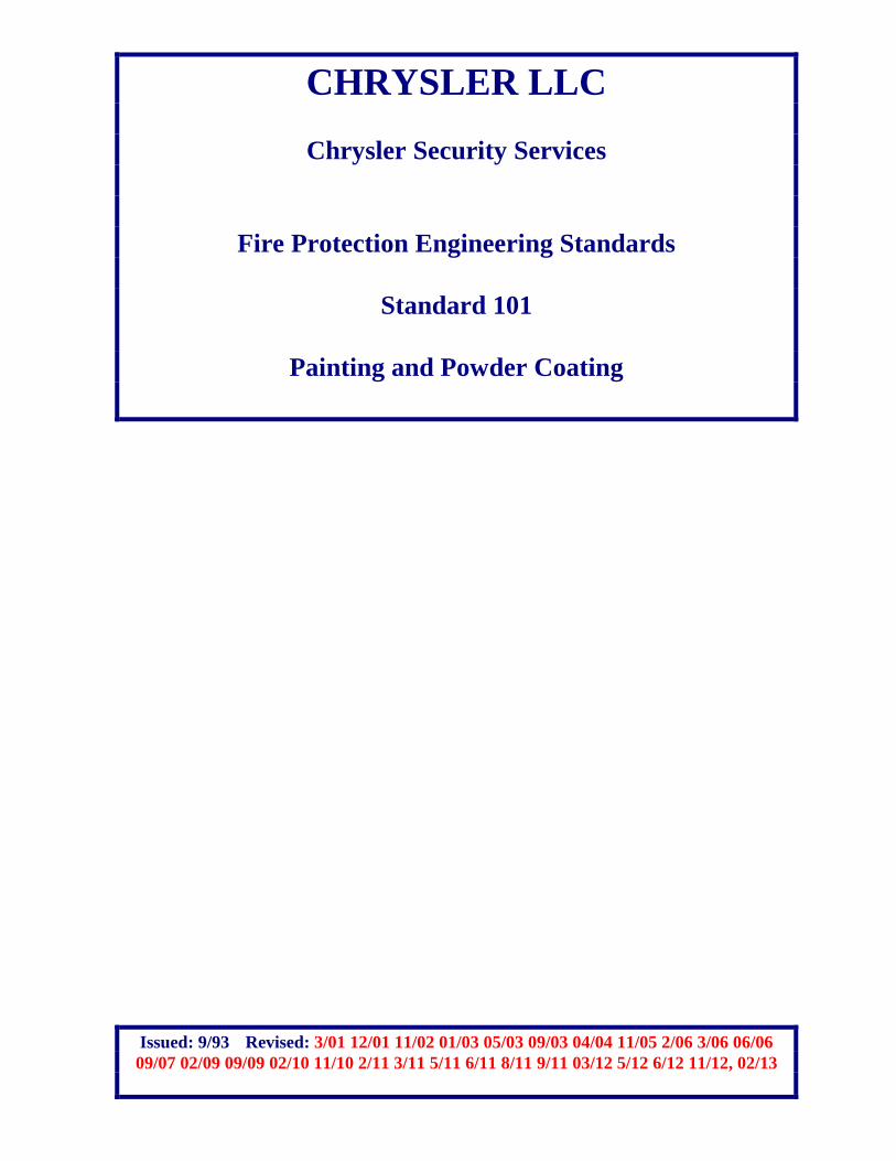
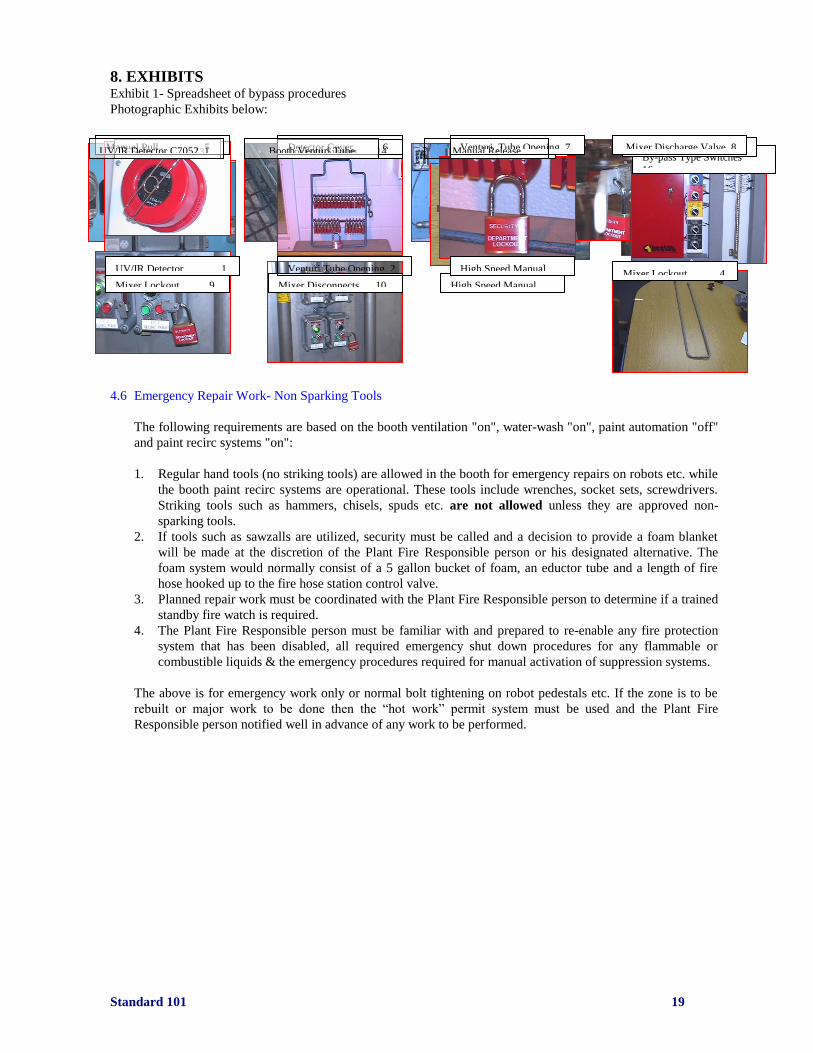
8. EXHIBITS Exhibit 1- Spreadsheet of bypass procedures
Photographic Exhibits below:
4.6 Emergency Repair Work- Non Sparking Tools
The following requirements are based on the booth ventilation "on", water-wash "on", paint automation "off"
and paint recirc systems "on":
1. Regular hand tools (no striking tools) are allowed in the booth for emergency repairs on robots etc. while
the booth paint recirc systems are operational. These tools include wrenches, socket sets, screwdrivers.
Striking tools such as hammers, chisels, spuds etc. are not allowed unless they are approved non-
sparking tools.
2. If tools such as sawzalls are utilized, security must be called and a decision to provide a foam blanket
will be made at the discretion of the Plant Fire Responsible person or his designated alternative. The
foam system would normally consist of a 5 gallon bucket of foam, an eductor tube and a length of fire
hose hooked up to the fire hose station control valve.
3. Planned repair work must be coordinated with the Plant Fire Responsible person to determine if a trained
standby fire watch is required.
4. The Plant Fire Responsible person must be familiar with and prepared to re-enable any fire protection
system that has been disabled, all required emergency shut down procedures for any flammable or
combustible liquids & the emergency procedures required for manual activation of suppression systems.
The above is for emergency work only or normal bolt tightening on robot pedestals etc. If the zone is to be
rebuilt or major work to be done then the “hot work” permit system must be used and the Plant Fire
Responsible person notified well in advance of any work to be performed.
FS-10CS 13
13
131313Detector13
Lockout System 14
Lockout Lock 15 By-pass Type Switches
16
Mixer Lockout 9 Mixer Disconnects 10
Mix
High Speed Manual
11 111Pull
Paint Recirc “U” Bend
12 12
Manual Pull 5
Detector Cover 6
Venturi Tube Opening 7
7
Mixer Discharge Valve 8
88
UV/IR Detector 1 Venturi Tube Opening 2
2 2pphoto 2
High Speed Manual
3 33333333333333Pull
Mixer Lockout 4
UV/IR Detector C7052 1
11 5
Booth Venturi Tube
Manual Release

Standard 101 20
5.0 Extinguishing Systems
5.1 Sprinkler Systems
5.1.1 General
Note: Underground fire mains are detailed in CFS 105 “New Construction”
Buildings in which paint storage, handling, and spray operations occur shall be 100% protected with
automatic sprinkler protection in accordance with this Standard.
Sprinkler systems designed to protect Paint Spray Rooms and Booths shall be of the “wet” pipe type.
Sprinkler systems designed to protect exhaust stacks and ovens (if required) shall be of the “dry” pipe
type. Systems (valve and trim) shall be located in accordance with Corporate and GRC
recommendations. All sprinkler control valves shall be easily accessible for inspection and not require
the use of a ladder. NOTE: If the conditions listed under Section 7.9 of this standard are met for ovens,
sprinkler protection is not required. However, a formal variance may be required by any local City
or State authority to omit sprinkler protection within any oven or other areas such as scrubber
(eliminator) tanks.
Note: See section 5.4.4.1 for option to eliminate sprinkler protection in an electrostatic spray zone
Sprinkler control sub valves and water flow switches shall be provided for systems with more than 20
heads.
Paint mix rooms shall be fed from their own riser. No other sub-risers shall be tapped off the riser
designated for the paint mix room.
Butterfly type sprinkler control valves shall not be utilized at Chrysler LLC Facilities
Sprinkler systems, alarm valves, and trim shall be provided to make the system functional in accordance
with latest edition of NFPA 13 and/or FM 2-8N, “Installation of Sprinkler Systems” as follows:
Wet Pipe Dry Pipe
OS&Y Valve OS&Y Valve
Alarm Valve Dry Pipe Valve
Fire Department Connection Fire Department Connection
Alarm Supervision Device Alarm Supervision Device
(Electrical or Mechanical) (Electrical or Mechanical)
Riser hydraulic data Air or Nitrogen Supply in piping
Gauges Gauges
Two inch drain Two inch drain
Inspectors test connection Inspectors test connection
Condensate drains
NOTE: It is acceptable to use an approved combination two-inch drain, inspector’s test and pressure
relief valve device.
Standard 101 21
5.1.2 Materials
Black steel pipe shall be used for non-freezing sprinkler system piping.
Galvanized or stainless steel pipe shall be used for dry, pre-action and eliminator tank sprinkler system
piping. Galvanized pipe shall not be used in heated areas such as ovens.
Schedule 10 and schedule 40 metallic pipes, for use in sprinkler systems, shall be UL or FM approved.
All pipes 6 inches and smaller must have a MIC coating applied by the Mill. Eight inch pipes and larger
shall be schedule 10 MIC coated on special order from the Mill. A letter from the Mill stating that the
pipe has MIC coating is required from the contractor. This letter shall be submitted to ME and as part of
the plan review to the Third Party Loss Consultant.
If the pipe is painted in the field or shop, the pipe id markings are not legible. In this case the Chrysler
ME Project Engineer or a member of the Fire Team must accept the pipe prior to painting.
Galvanized coated pipe is not acceptable for use in wet systems as an alternative to MIC coated pipe.
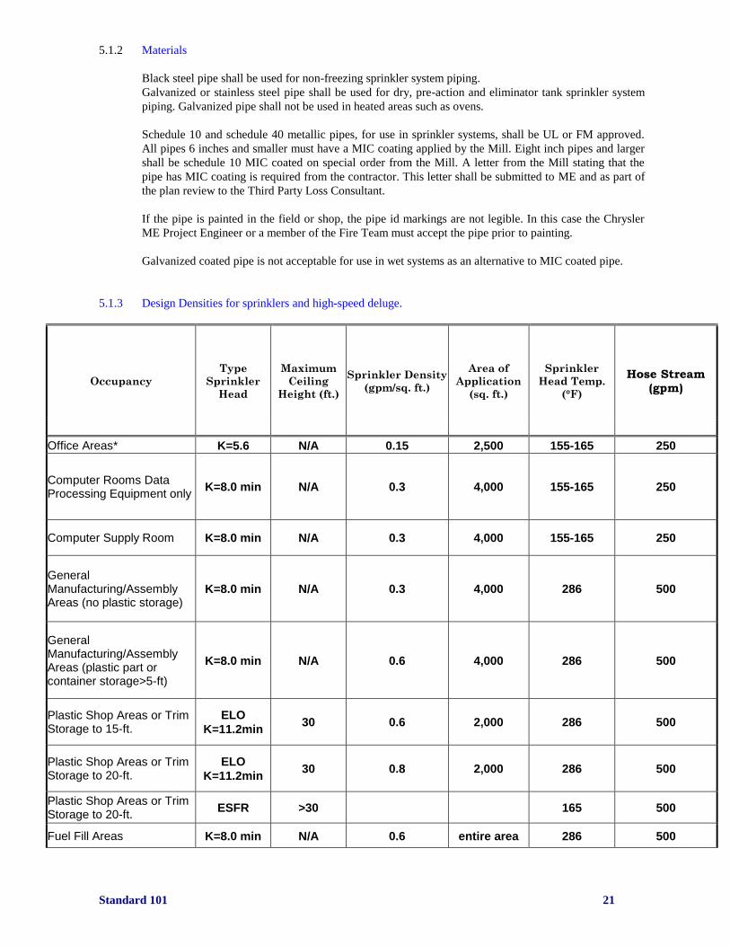
5.1.3 Design Densities for sprinklers and high-speed deluge.
Occupancy
Type
Sprinkler
Head
Maximum
Ceiling
Height (ft.)
Sprinkler Density
(gpm/sq. ft.)
Area of
Application
(sq. ft.)
Sprinkler
Head Temp.
(°F)
Hose Stream (gpm)
Office Areas* K=5.6 N/A 0.15 2,500 155-165 250
Computer Rooms Data Processing Equipment only
K=8.0 min N/A 0.3 4,000 155-165 250
Computer Supply Room K=8.0 min N/A 0.3 4,000 155-165 250
General Manufacturing/Assembly Areas (no plastic storage)
K=8.0 min N/A 0.3 4,000 286 500
General Manufacturing/Assembly Areas (plastic part or container storage>5-ft)
K=8.0 min N/A 0.6 4,000 286 500
Plastic Shop Areas or Trim Storage to 15-ft.
ELO
K=11.2min 30 0.6 2,000 286 500
Plastic Shop Areas or Trim Storage to 20-ft.
ELO
K=11.2min 30 0.8 2,000 286 500
Plastic Shop Areas or Trim Storage to 20-ft.
ESFR >30 165 500
Fuel Fill Areas K=8.0 min N/A 0.6 entire area 286 500
Standard 101 22
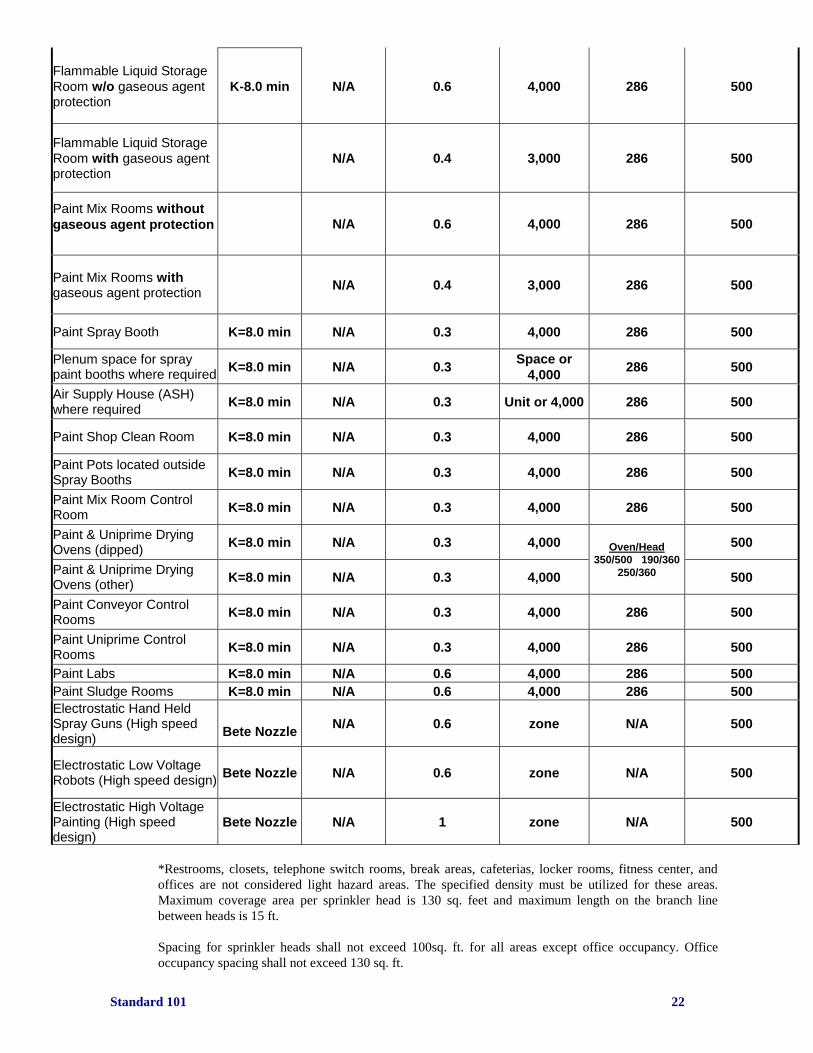
Flammable Liquid Storage
Room w/o gaseous agent protection
K-8.0 min N/A 0.6 4,000 286 500
Flammable Liquid Storage
Room with gaseous agent protection
N/A 0.4 3,000 286 500
Paint Mix Rooms without
gaseous agent protection
N/A 0.6 4,000 286 500
Paint Mix Rooms with gaseous agent protection
N/A 0.4 3,000 286 500
Paint Spray Booth K=8.0 min N/A 0.3 4,000 286 500
Plenum space for spray paint booths where required
K=8.0 min N/A 0.3 Space or
4,000 286 500
Air Supply House (ASH) where required
K=8.0 min N/A 0.3 Unit or 4,000 286 500
Paint Shop Clean Room K=8.0 min N/A 0.3 4,000 286 500
Paint Pots located outside Spray Booths
K=8.0 min N/A 0.3 4,000 286 500
Paint Mix Room Control Room
K=8.0 min N/A 0.3 4,000 286 500
Paint & Uniprime Drying Ovens (dipped)
K=8.0 min N/A 0.3 4,000 Oven/Head
350/500 190/360
250/360
500
Paint & Uniprime Drying Ovens (other)
K=8.0 min N/A 0.3 4,000 500
Paint Conveyor Control Rooms
K=8.0 min N/A 0.3 4,000 286 500
Paint Uniprime Control Rooms
K=8.0 min N/A 0.3 4,000 286 500
Paint Labs K=8.0 min N/A 0.6 4,000 286 500
Paint Sludge Rooms K=8.0 min N/A 0.6 4,000 286 500
Electrostatic Hand Held Spray Guns (High speed design)
Bete Nozzle N/A 0.6 zone N/A 500
Electrostatic Low Voltage Robots (High speed design)
Bete Nozzle N/A 0.6 zone N/A 500
Electrostatic High Voltage Painting (High speed design)
Bete Nozzle N/A 1 zone N/A 500
*Restrooms, closets, telephone switch rooms, break areas, cafeterias, locker rooms, fitness center, and
offices are not considered light hazard areas. The specified density must be utilized for these areas.
Maximum coverage area per sprinkler head is 130 sq. feet and maximum length on the branch line
between heads is 15 ft.
Spacing for sprinkler heads shall not exceed 100sq. ft. for all areas except office occupancy. Office
occupancy spacing shall not exceed 130 sq. ft.
Standard 101 23
Ductwork shall be designed for a minimum of 30-gpm for the most remote 10 sprinklers. Sprinkler
protection is required in ductwork 100 square inches of cross-sectional in rectangular or square area and
above whenever the ducts are combustible, handle solvent laden air, is a pathway for combustible dusts
or particulate matter or where combustible residues can collect on the ductwork interior. Round ductwork
10” in diameter and larger requires sprinkler protection. Maximum spacing between sprinkler heads shall
be 10ft.
Exhaust ducts shall be based upon a minimum of 30 gpm per sprinkler for the most remote 10 sprinklers,
except for ductwork associated with scrubber (eliminator) tanks. For scrubber tanks, design shall be
based upon a minimum 30-gpm per sprinkler for the most remote 20 sprinklers. Maximum spacing
between sprinkler heads shall be 10ft.
Exhaust stack fire protection:
An alternative to thermal control valves or dry pipe protection for exhaust stacks is to install a self-actuating pilot
operated diaphragm control valve system as described below. One self-acting pilot operated diaphragm control
valve shall protect one stack unless approved by Corporate Fire Specialist based upon prior submission stating a
description of operation and drawing detailing proposed system.
A 1½-inch wet pipe main feeding an approved self-acting pilot operated diaphragm control valve will be installed
a minimum of 1½-feet below the roof deck if there is a damper in the exhaust stack or 2½-feet below the roof
deck if no damper is provided in the exhaust stack. Note: If there is a potential for long period of sub-freezing
weather conditions, consideration should be given to locating the self-acting pilot operated diaphragm
control valve further down below the roof deck.
From the 1½-inch wet pipe feed main install a ¼-inch pilot line (piping), used to provide pressure to the upper
chamber of the self-acting pilot operated diaphragm control valve, maintaining it in a normally closed position.
On this 1/4–inch pilot line shall be a 1/4–inch union fitting, a 1/4–inch ball valve, a ¼-inch spring loaded check
valve installed to allow water flow towards the upper chamber of the self-acting pilot operated diaphragm control
valve, and a 1/2-inch 155°F dry pendent sprinkler head screwed into a ¼ x ½ x ¼ fitting.
The dry sprinkler shall be inserted horizontally into the exhaust stack located at least two (2) feet below the roof
deck or just below the bottom of the self-acting pilot operated diaphragm control valve.
The discharge side of the self-acting pilot operated diaphragm control valve shall be used to supply water up to
four (4) open head upright sprinklers in the exhaust stack installed 8 to 10 feet between sprinklers vertically within
the exhaust stack (3 heads above the roof deck and 1 head below).
Approved valves as of 3/1/2013:
Cal-Val model 7100
All new scrubber tank installations shall not be provided with sprinkler protection unless required by the
local AHJ. Piping shall be stainless steel or galvanized. Sprinkler heads shall be wax coated.
Automatic sprinkler protection is required in exhaust ductwork from the scrubber tank to vapor
abatement system (RTO). This includes any ductwork open to scrubber tank (that contains moist
residue) that is associated with scrubber tank. Sprinkler protection within this ductwork shall be
designed to provide a minimum 30-gpm from the most remote 20 sprinklers plus 500-gpm hose stream
allowance.
All ASH’s containing combustible filters shall be protected with automatic sprinkler protection. All
ASH’s supplying tempered air to spray paint booths shall be protected with automatic sprinklers
regardless of filter media.
If the plenum spaces contain combustible filters in the lower plenum, automatic sprinkler protection shall
be provided. If plenums contains non-combustible (Class ‘A’) filters, automatic sprinkler protection is
only required in the spray painting area on a wet pipe sprinkler system. HOWEVER, IF LOCAL AHJ
REQUIRES, SPRINKLER PROTECTION SHALL BE INSTALLED IN ALL PLENUM SPACES.
Standard 101 24
NOTE: If air distribution system contains combustible filters, sprinkler protection shall be installed in the
upper plenum space.
NOTE: For hydraulic calculations, contractor shall use 1.4 times the square foot of the remote area for
the length of the remote branch line.
5.1.4 Sprinkler Heads/Fittings
Sidewall sprinkler heads shall not be used in accordance with this Standard.
All sprinklers which are susceptible to being coated with paint or other foreign materials in production
spray booths, production spovens and maintenance spray booths shall be protected by an approved
method such as:
Bags over sprinklers - 0.003 inch (0.076 mm) cellophane. Sprinkler heads shall be covered with
protective cellophane bags (available from Corporate).
Bags shall be attached to the sprinkler head base using zip ties or rubber bands. Zip ties and rubber bands
shall be placed so that they do not interfere with the sprinkler head discharge. Tape is not an acceptable
method for securing the bags.
OR
Wax/Lead coated sprinklers (normally used in corrosive atmospheres)
Sprinklers are required under stairwells and open mesh grating /screen guarding/cribbing (over 4 ft.
wide) except over main aisles where storage of combustibles is not permitted. Approved intermediate
type sprinklers or sprinklers with water shields are required.
Any fittings, valves etc. over a heated surface shall be rated at least 50°F higher than the maximum
anticipated exterior surface temperature.
Any drain pipe from the sprinkler system that does not drain to the outside or a drain pipe shall be fitted
with a 1½-inch IPT male fitting. This will allow a standard fire hose to be connected for draining to a
safe location.
5.1.5 Exhaust Ducts/Stacks
All exhaust ducts involving paint spray operations, except incinerator stacks, shall be protected with
sprinklers controlled by a separate OS&Y control valve. Sprinkler spacing shall be between 10 to 12 feet
(on center). Sprinklers shall be provided within stacks to a height of 30 feet above the roof level of a
building. Emergency RTO exhaust (by-pass spill) stacks connected to an RTO will require automatic
sprinklers for the entire height of the stack. Sprinklers shall be accessible by installing access doors or
use approved “Flex-Head” type sprinklers. Inspection doors for roof level sprinklers shall be a minimum
of 2 ft. X 2 ft., a maximum of 5 ft. from the roof level. This door shall be latched so it opens out from the
duct. No tools shall be required to open the door.
Paint Spray Booth exhaust sprinkler protection shall be of a “wet’ pipe type to the roof level of a building
and of a “dry” pipe type for all protection above the roof level. NOTE: In any stack where excessive
vibration is a concern, consideration may be given to the installation of “Flex-Head” style sprinklers. Any
pipe on a dry system shall be galvanized. Stainless steel couplings shall be utilized for sprinkler head
access from a hatch within 3-4 feet of the head. “Flex Head” style sprinklers are an alternative method of
protecting the exhaust stacks. Compression type fittings shall be used for duct penetration and not a
gasket with the pipe through the gasket.
Thermal control valves shall not be utilized in lieu of dry pipe valves. They contain silicon based grease
and are no longer being manufactured.
Standard 101 25
All ductwork 48 inches and wider shall have additional sprinkler protection provided for areas below the
ductwork.
All areas where multiple segments of ductwork or piping are installed such that areas 48 inches and wider
are formed constituting substantial blockage to normal sprinkler coverage, shall have additional sprinkler
protection provided for the areas below the ductwork and/or piping.
5.1.6 Sprinkler Water-flow /Supervisory Devices
System supervision for “wet” pipe sprinkler systems shall consist of an approved water flow switch.
System supervision for “dry” pipe sprinkler systems shall consist of low air pressure alarm and water
flow pressure switch .Water-flow supervision shall be provided on all sub-systems such as misc. booths,
pits, and decks for systems 20 heads or more. Each water-flow device shall have a specific address
assigned at the fire alarm panel and release control panel.
5.2 Fire Hose Stations
NFPA No. 13, 2007 edition does not require 1.5-inch fire hose drops or hose stations if approved by
local AHJ. If fire hose drops are required by local AHJ, fire hose control valves (1.5”) must have built-in
pressure limiting device that limits pressure to 80-psi. Pressure limiting disks shall not be used as a
method to reduce pressure.
If required, fire hose stations shall be installed in accordance with the latest edition of NFPA No. 13,
“Installation of Sprinkler Systems”.
Fire hose stations shall be spaced such that 100 feet of fire hose and 30 feet of nozzle range can reach all
portions of the area protected by the fire hose stations. Two coupled 50 feet lengths shall be provided to
accomplish the 100 ft. requirement
5.3 Portable Fire Extinguishers
Fire extinguishers shall be provided for all paint shop areas except ovens and spray booths. All
extinguishers shall be installed with a maximum travel distance of 75 feet.
Carbon dioxide units shall be provided around electrical equipment.
Carbon dioxide units shall be provided around flammable liquids.
Dry chemical units shall not be used within a paint shop.
Water extinguishers shall be provided where class “A” combustibles are present within a paint shop.
Class “K” extinguishers shall be provided in all operating kitchens where the local AHJ requires them to
be installed. Proper class “K” signage shall be provided.
The sizes (ratings), manufacturer, and distribution of the units shall be directed by Corporate Fire. The
following extinguisher sizes are the only sizes approved by Corporate Fire:
2.5 gallon water
2.5 gallon foam
6 liter class “K” (used only in kitchen areas)
15 lbs carbon dioxide
20 lbs dry chemical class “B-C” and class “A-B-C” (not utilized in paint shops)
20 lbs dry powder class “D” (not utilized in paint shops)
Standard 101 26
5.4 Special Hazard Systems
5.4.1 General
Within the electrostatic robotic and bell zones of all Paint Spray Booths, fire detection and suppression is
provided within the spraying zone (area) of the booth and within the various cabinets/towers associated
with paint spraying equipment and paint changing operation.
Fire detection and suppression is also provided within all electrostatic manual paint spray zones (except
where approved hand guns are used).
Within electrostatic bell zones, the fire detectors are arranged to discharge a gaseous agent (HFC-227ea
(FM-200)) through the shaping air of the bells and/or discharge the High-Speed Water Spray (deluge)
system.
Within the various cabinets/towers, fire detectors are installed and positioned to detect fires near the
paint changer. Also, the Clean Wall cabinets/towers, located within the Clean Room, also contain at
least one additional optical flame fire detector at the top of the enclosure where paint and solvent lines
enter the cabinet.
All Special Hazard Systems shall be designed and installed by manufacturer’s authorized and
licensed contractors/representatives with automotive paint shop fire protection experience.
If a project is sub-divided into two operations i.e., spray booth contract & automation integration
contract, it is possible to have two different contractors installing fire suppression systems. All
equipment used in a project must be the same manufacturer and approved by the Corporate Fire
Prevention Engineer.
5.4.2 Gaseous Agent in Paint Spray Booths and Associated Spraying Equipment
HFC-227ea (FM-200) or another approved agent shall be provided in the following areas:
1. Clean wall cabinets/towers containing paint/solvent lines
2. Overhead bell cabinets with paint/solvent lines
NOTE: Each manufacturer’s Paint Application Equipment must be reviewed by Corporate Fire
Prevention Engineer and GRC for quantity and location of fire detectors.
Design concentration shall be specified by the gaseous agent manufacturer with a minimum discharge
time of ten (10) seconds. For HFC-227ea (FM-200), the minimum design concentration is 9.8%.
Each system shall have main agent storage cylinders only. A spare set of cylinders (bottles) for the
largest hazard shall be kept on site unless a contractor can certify he can provide a refill of the approved
agent within 4 hours. If more than one type of gas agent is used within a given facility, a spare set of
cylinders for each agent shall be kept on-site. They shall be stored in the plant at the direction of the local
Plant’s Fire Responsible person
The system agent storage cylinders shall be located as close to the protected hazard as possible to
provide optimum discharge time.
The gaseous agent (HFC-227ea) through the shaping air shall be arranged to be the primary fire
suppression media and high speed water spray as the secondary media. Fire detectors have programmable
time delay modes. If a fire detector detects and extinguishes a fire within 5 seconds by discharging the

Standard 101 27
HFC-227ea (FM-200) system, the high-speed (deluge) water spray discharge can be programmed to
automatically abort. NOTE: Pulling a manual pull station will automatically release both the HFC-227ea
(FM-200) for the given zone and discharge the high-speed (deluge) water spray.
If fire detector within any clean wall cabinet/tower or overhead bell cabinet detects a fire, only the
gaseous agent shall discharge within the specific zone.
The HFC-227ea (FM-200) systems for the automation equipment shall be grouped to not discharge
simultaneously into all enclosures but into the overheads, left sides and right sides if detectors in that
group of equipment “see” a fire using the fiber optic detectors. This will provide three (3) zones of
discharge.
A laminated graphics drawing (11in. x17in.) shall be provided for each protected zone mounted in the
appropriate release cabinet. This drawing shall show locations of all optical flame detectors, manual
pulls, fiber optic detectors, alarm devices and agent cylinders. The drawing shall match the custom
messages provided on the panel output. A set of "as-built drawings" shall be kept in the release control
panel enclosure.
5.4.2.1 Conversion of Paint Spray Robots to Robo-bells
a. Non Electrostatic
Fire protection consists of standard booth sprinklers (see chart 5.1.3 for sprinkler density)
b. Electrostatic (low and high voltage)
1) Fire protection consists of high speed deluge for the zone designed for a minimum of
0.6 gpm / sq. ft. for the zone
2) Gaseous agent protecting the applicator arm if there is no “slot” in the lower portion of
the arm to drain solvent and paint into the water wash
3) Flame detection (fiber optics) for discharging gaseous agent in the applicator arm
4) Fire suppression release panel. This can be the existing release panel for the high speed
deluge system
5) Tie in of alarms to the building fire alarm system
Alternative for items 2 through 5 would be to drill holes or provide a milled slot in the lower
portion of the applicator arm so that any fluid leakage would discharge into the water wash.
These holes shall be a minimum of 1 inch and at least 2 to 3 holes would be necessary. The
milled slot shall be a minimum of 1 inch wide.
Holes or slots shall be approved by the Corporate Fire Team and Third Party Consultant before
items 2 through 5 are eliminated.
5.4.3 Gaseous Agent for Hazardous Rooms and High Value Rooms
Gaseous agent HFC-227ea (FM-200) or HFC-125 (ECARO) shall be provided in the following areas:
- Paint Mix Rooms
- Paint Conveyor Control Rooms
- Paint Mix Computer Control Rooms
Design concentration shall be per NFPA and/or Factory Mutual Data Sheets. Minimum concentration for
HFC-227ea (FM-200) is 9.8% and HFC-125 (ECARO) is 12.2% for Hazardous Rooms and 7% for
computer rooms.
Release Control Panel shall not be located within the protected room regardless of type of panel.
The following equipment shall be specified as a minimum when designing a gaseous agent fire
suppression system:
1. Cylinders (main only) with liquid level indicators and supervisory pressure switches
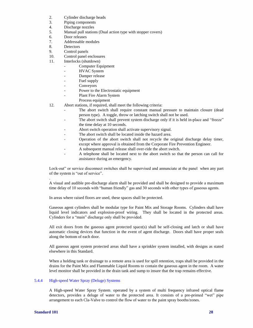
Standard 101 28
2. Cylinder discharge heads
3. Piping components
4. Discharge nozzles
5. Manual pull stations (Dual action type with stopper covers)
6. Door releases
7. Addressable modules
8. Detectors
9. Control panels
10. Control panel enclosures
11. Interlocks (shutdown)
- Computer Equipment
- HVAC System
- Damper release
- Fuel supply
- Conveyors
- Power to the Electrostatic equipment
- Plant Fire Alarm System
Process equipment
12. Abort stations, if required, shall meet the following criteria:
- The abort switch shall require constant manual pressure to maintain closure (dead
person type). A toggle, throw or latching switch shall not be used.
- The abort switch shall prevent system discharge only if it is held in-place and “freeze”
the time delay at 10 seconds.
- Abort switch operation shall activate supervisory signal.
- The abort switch shall be located inside the hazard area.
- Operation of the abort switch shall not recycle the original discharge delay timer,
except where approval is obtained from the Corporate Fire Prevention Engineer.
- A subsequent manual release shall over-ride the abort switch.
- A telephone shall be located next to the abort switch so that the person can call for
assistance during an emergency.
Lock-out” or service disconnect switches shall be supervised and annunciate at the panel when any part
of the system is “out of service”.
.
A visual and audible pre-discharge alarm shall be provided and shall be designed to provide a maximum
time delay of 10 seconds with “human friendly” gas and 30 seconds with other types of gaseous agents.
In areas where raised floors are used, these spaces shall be protected.
Gaseous agent cylinders shall be modular type for Paint Mix and Storage Rooms. Cylinders shall have
liquid level indicators and explosion-proof wiring. They shall be located in the protected areas.
Cylinders for a “main” discharge only shall be provided.
All exit doors from the gaseous agent protected space(s) shall be self-closing and latch or shall have
automatic closing devices that function in the event of agent discharge. Doors shall have proper seals
along the bottom of each door.
All gaseous agent system protected areas shall have a sprinkler system installed, with designs as stated
elsewhere in this Standard.
When a holding tank or drainage to a remote area is used for spill retention, traps shall be provided in the
drains for the Paint Mix and Flammable Liquid Rooms to contain the gaseous agent in the room. A water
level monitor shall be provided in the drain tank and sump to insure that the trap remains effective.
5.4.4 High-speed Water Spray (Deluge) Systems
A High-speed Water Spray System, operated by a system of multi frequency infrared optical flame
detectors, provides a deluge of water to the protected area. It consists of a pre-primed “wet” pipe
arrangement to each Cla-Valve to control the flow of water to the paint spray booths/zones.

Standard 101 29
All zones that utilize electrostatic application equipment, both automatic and manual, shall be protected
by high-speed water spray (deluge) systems.
Each zone (Paint Spray Booth) shall be piped individually from the “process loop” water supply and
shall have Cla-Valves for use with a maximum of two water spray nozzles (Bete nozzles) per valve. The
location of the discharge nozzles shall not interfere with the spray equipment or be located directly above
the spray equipment or vehicle.
Sprinkler and water spray piping shall not interfere with the changing of the booth ceiling filters. No
piping shall be routed over the filters. Pipe shall be routed within the filter support with the main header
located outside the plenum running parallel to the catwalk. Welded stainless steel couplings in the ceiling
support steel, installed by the spray booth contractor, shall connect the sprinkler or Bete nozzle pipe to
the supply in the air plenum. Pipe that passes through the plenum wall shall be caulked (no silicone
material) and fitted with a stainless steel escutcheon plate.
Cla-Valves shall be spaced at a maximum of 10 feet on center down each side of the zone. One Cla-
Valve shall be connected to a maximum of two Bete nozzles.
All Cla-Valves shall be provided with stainless steel flexible braided hose and fittings between the pilot
line and the valve.
The pilot line must be a minimum of ½ inch diameter galvanized pipe or stainless tubing. The pilot line
system must be looped within each zone.
Hydro-electric operated manual pull stations shall be provided (minimum one per side of the booth per
zone) to actuate the high-speed water spray (deluge) system. The stations shall signal the release panel
and in turn, release the pilot line pressure and activate the interlocks.
5.4.4.1 Optional method to eliminate automatic wet pipe sprinkler system with the approval of the local AHJ
In this installation the sprinkler heads act as an alternative actuation method for the high speed deluge
system only and not used for fire suppression purposes. Sprinkler heads are not being used for fire
suppression or control but only as a method to discharge the high-speed deluge system. These zones will
be protected only by the high-speed deluge protection which can be activated by one of three methods.
Method 1: Optical flame detectors and release control panel
Method 2: Activation of manual release station(s) will drop pressure on pilot line and open Cla-Valves
Method 3: Fusing of any sprinkler head on any Cla-Valve pilot line will drop pressure on pilot line and
open Cla-Valves
Sprinkler heads shall be half inch (1/2 in.) orifice
One sprinkler head shall be installed for each Cla-Valve pilot line
An option to eliminate installation of an automatic wet pipe sprinkler system is to install automatic
sprinkler system heads connected to the pilot line of the deluge system. The sprinkler heads shall be rated
a maximum of 165 degrees F. A wire braided hose is “T” tapped into the half inch pilot line prior to the
Cla-Valve. The male end of the braided hose is screwed into a rigid metallic bulk head fitting on the filter
media support structure. The half inch orifice sprinkler head is than screwed into the female end of the
bulk head fitting.
See photo: To be placed in the future
Standard 101 30
5.5 Low Level Ventilation
5.5.1 Room Ventilation
Ventilation in the Paint Mix Room and Flammable Liquids Storage Room shall be at least one cubic foot
per minute (cfm) of low level exhaust ventilation per square foot of floor area (1:1). Minimum
ventilation is 150 cfm. Proof of ventilation through sail switches, end shaft monitoring etc. shall be
provided and locally alarmed. The exhaust pick-up points shall be a maximum of 12 inches above the
finished floor.
5.5.2 Explosion Relief Venting
Explosion relieving venting (for the Paint Mix Room only) shall be provided at a ratio of 1 square foot
per 50 cubic feet of room volume (1:50). Explosion relief venting can be designed into either the roof
and/or exterior walls in conjunction with building/room design parameters.
Preferred method of explosion relief venting is through external walls with attached cables to restrain the
panels. Explosion relief venting through the roof should be used only if it can not be provided/designed
through external walls.
Explosion relief venting shall relieve at 20-25 pounds per square foot.
Wall explosion resistance shall be 100-125 pounds per square foot.
Ratio of explosion relief venting to explosion resistance should be 1:5.
5.5.3 Smoke and Heat Venting
Where local authorities require smoke and heat venting, a building variance to omit should be obtained
by the architect/contractor.
If the variance can not be obtained, smoke and heat venting shall be provided at a ratio of 1 square foot
per 30 square feet of room floor area (1:30).
5.6 Additional Fire Protection for Hazardous Rooms and High Value Rooms
All material handling equipment in the Paint Mix and Paint Storage Rooms shall be of non-sparking type
and shall have a safety rating of EE or DY in accordance with NFPA No. 505, “Industrial Lift Trucks”.
All dispensing equipment in accordance with this Standard shall be a manual drum pump or “dead man”
type. All dispensing equipment shall be properly grounded.
Purge pots, if used, shall be provided with flame arrestors.
Standard 101 31
6.0 Detection Systems
6.1 Detector Types
Detectors shall be of the photoelectric type and/or multi-spectrum (IR3) optical fire detectors as follows:
- Electrostatic Painting Zones: Multi-spectrum IR – solvent
Multi-spectrum IR - waterborne
- Electrostatic Manual Painting Zones: Multi-spectrum IR – solvent
Multi-spectrum IR - waterborne
- Paint Mix Room: Multi-spectrum IR
- Flammable Liquid Storage Room: Same as Paint Mix Rooms
- Paint Mix Computer Control Room: Addressable Smoke Sensors
- Conveyor Control Room: Addressable Smoke Sensors
Detectors used in mix or storage rooms, shall be sequentially zoned for activation of the suppression
system.
6.2 Detector Quantities
Suggested detector quantity for electrostatic zones except Bell zones:
Spray Zone Length Multi-spectrum Detectors
20 feet 4
25 feet 4
30 feet 6
40 feet 8
50 feet 8
60 feet 8
70 feet 10
80 feet 10
Suggested detector quantity for electrostatic Bell zone with six side and one overhead (three
bells) (Clean Wall type paint spray booth):
Multi-spectrum IR Fiber Optic
Sixteen Nine PM9-SBE
Detector quantity for electronic Bell zone with greater than 9 bells:
Each Clean Wall Side cabinet Each Clean Wall Overhead
Two X-3301 (one in cabinet, Four X-3301 (one in each tower,
one in booth) two in booth)
One PM9-SBE w/ 25’ fiber cable Three PM9-SBE w/ 45’ fiber cable
Manufacturer recommendations concerning quantity and location of detectors and controllers that vary
from this Standard shall be submitted to the Corporate Fire Prevention Engineer and GRC for review and
approval.
All areas within the protected zones shall be covered by a minimum of two sensors.

Standard 101 32
6.3 Equipment
6.3.1 General
Equipment located in Paint Spray Rooms/Booths, Mix Rooms, and Flammable Liquid Storage Rooms
shall meet hazardous location requirements as set forth in NFPA No. 70. “National Electric Code
Equipment in other areas shall meet hazardous location requirements as set forth in NFPA No. 70 where
required by the AHJ.
Each control panel shall be provided with a terminal strip or block for connection with the plant’s
proprietary fire alarm system. The location of the release control panel shall be determined in
consultation with PEM, local Plant Engineering and Corporate by the installing contractor.
High-speed water spray (deluge) systems and gaseous agent release control panels shall be UL, ULC
Listed and/or Factory Mutual approved. Each release panel shall provide separate addressable points and
annunciation as follows:
Water flow “Alarm” signal
Water control valve position (tamper alarm if required)
General “Trouble” signal
Low agent pressure “Supervisory” signal
Manual pull activation
Detector activation alarm
Detector activation fault
Detector activation early warning
Each by-pass or inhibit switch
The release control panel shall have a custom display message for each of the above listed conditions and
shall log into its’ non-volatile memory whenever any of the conditions activate.
Release control panel enclosures shall contain the following equipment:
Detector controllers, where applicable Supervised Addressed Selector Switches
Release panel with non-volatile history buffer A. AC Power
Addressable control and release modules B. Battery Power
Standby batteries and charger (24 hr. standby) C. Detector Power
Terminal strip for fire alarm connection D. Deluge Disable
110 volt appliance outlet E. Clean Agent Disable
Power supply F. Interlock Disable
Shock protective covers for devices equal or over G. Purge Fan control (if provided)
50 volts
Each paint zone that has a high-speed water (deluge) spray system or detection system shall have an
individual detection panel and battery system (except where an Eagle Quantum Premier system with a hot
backup is utilized). In all cases, each zone shall operate independently of other zones. For booth
modifications or equipment upgrade it is permissible to connect all basecoat zones into one control panel
and clear coat zones into one panel per spray booth.
The factory qualified installing contractor will utilize one Detector Electronics Eagle Quantum Release
Control panel with a second Eagle Quantum Release Control panel wired as an automatic “hot” backup.
These panels will be utilized to control all zones within one or more spray booths. These panels must
communicate with local panels (I/O) at each spray booth. Each local I/O panel will provide the ability to
control all bypass & disable functions at the booth. A panel mounted touch screen graphics display
package shall be included. This graphics shall display the overall booth(s) layout. If an alarm signals
then the specific booth that is in alarm shall display.
The Eagle Quantum System main and sub control panels shall be located by the installing contractor after
consultation with PEM, Plant Engineering, local Fire Responsible Person and Corporate.

Standard 101 33
The local I/O sub panels will have three visual notification devices as follows.
1) Clear horn/strobe = any alarm within the spray booth
2) Blue strobe=Any of the zones within the booth is disabled
3) Amber strobe =A fault in any device within the special system.
The release control panel’s outer most enclosure shall have a locking mechanism (hasp) that can be
secured with a pad lock. This pad lock shall be supplied to the installing contractor by the local G4S
Secure Solutions Site Security Manager.
The local electrical circuit breaker supplying power to the release control panel shall have a breaker lock,
installed by the fire suppression contractor and painted red. The location of the power panel and breaker
number shall be marked inside of the control panel enclosure in 1 inch lettering.
The panel backup batteries shall have the date of installation of the batteries marked on them.
6.3.2 Wiring Requirements
Wiring requirements for the complete system shall be per manufacturer specifications. By-pass switches
must be located inside control cabinets and shall be accessible only to the local G4S Secure Solutions
Security Dept.
All electrical conduit/penetrations shall enter fire release control enclosures from the side of
enclosure only.
All penetrations and terminations made to the fire release control enclosure shall be made or
supervised by the supplier of the fire release panel and enclosure.
Solid wires shall not be permitted regardless of gauge size.
Control modules, releasing modules, relay modules, monitoring modules, batteries, purge fan
switches, etc. must be located within lockable Control Panel enclosure unless approved by
Corporate Fire Prevention Engineer. Modules shall not be located within non-fire related
equipment cabinets or enclosures.
6.4 Signaling
Notification appliances shall be by visual and/or audible means as designated below:
- Automatic Painting Zones: Audible/Visual at alarm panel
- Manual Painting Zones: Audible/Visual at alarm panel
- Paint Mix Rooms: Audible/Visual*
- Flammable Liquid Storage Rooms: Audible/Visual*
- Computer Control Room - Paint Mix Room: Audible/Visual*
- Conveyor Control Room: Audible/Visual*
* Audible and visual alarms are required for each protected space at both the entry and exits to the room.
The strobes shall continue to flash until the alarm silence is pressed in the release control panel.
Activate notification appliances (audible/visual) for each of the following events:
- Release of gaseous agent or high speed water deluge
- Manual Release (at cylinders or manual pull stations)

Standard 101 34
6.5 Interfaces/Interlocks
6.5.1 General
Fire protection systems shall be compatible with and shall provide a signal and/or dry contacts for
monitoring by the following systems on alarm condition:
- Building proprietary fire alarm system
- Conveyors (For shutdown)
- High Voltage Paint Application (automation) Equipment (For shutdown)
- Paint Supply (For shutdown)
- Computer Equipment (For shutdown)
Liquid spray booth exhaust & supply air shall remain "on" at all times except where an individual ASH is
interlocked as a result of water flow within the given ASH.
Air supplies to individual paint cabinets that are protected with gaseous agents may be required to be
shut off or utilize a damper(s) interfaced with the clean agent system.
Spoven interlocks as well as modified final spot repair shall be interlocked such that the spot infrared
lamps can not be energized if spray operations are being used and visa versa. Also the downdraft
ventilation shall be interlocked such that if it is lost then the lamps and spray can not be used. This can be
done through a sail switch or other approved method.
All bypass interlock switches must be accessible to only Security and alarmed to the building fire alarm
system when in bypass.
All safety interlocks shall be direct (hard) wired to the shut-down devices and not the
programmable logic controller (no software interlock) unless approved by Corporate Fire
Engineer and GRC.
Software interlocks will be considered only when they are connected to the Emergency Stop
circuit. Interlocks can not be bypassed except by the supervised bypass switches located in the fire
protection control panel enclosure.
Interlocks connected by software shall comply with the additional requirements:
1. The shutdowns are programmed in the PLC safety logic
2. Access to the safety logic is by password only by the system manufacturer
3. Any changes to the safety logic must be verified and retested by Corporate and GRC
Note: Interlock modules shall be located within the locked fire release control enclosure. Other locations
are not acceptable.
6.5.2 Fiber Optic Infrared Detection Systems
See references in other sections.
6.6 Manual Release Stations
Manual release stations shall be provided for:
- High-speed Water Spray zones
- Gaseous Agent Protected Areas
Manual release stations for high-speed water spray operating system shall operate hydraulically. Manual
release stations for gaseous agent shall release electrically.
Electrically operated manual release stations shall be of the dual action type. A stopper cover is required.
Hydraulically operated manual release stations shall be tied directly to the Cla-Valve pilot line.
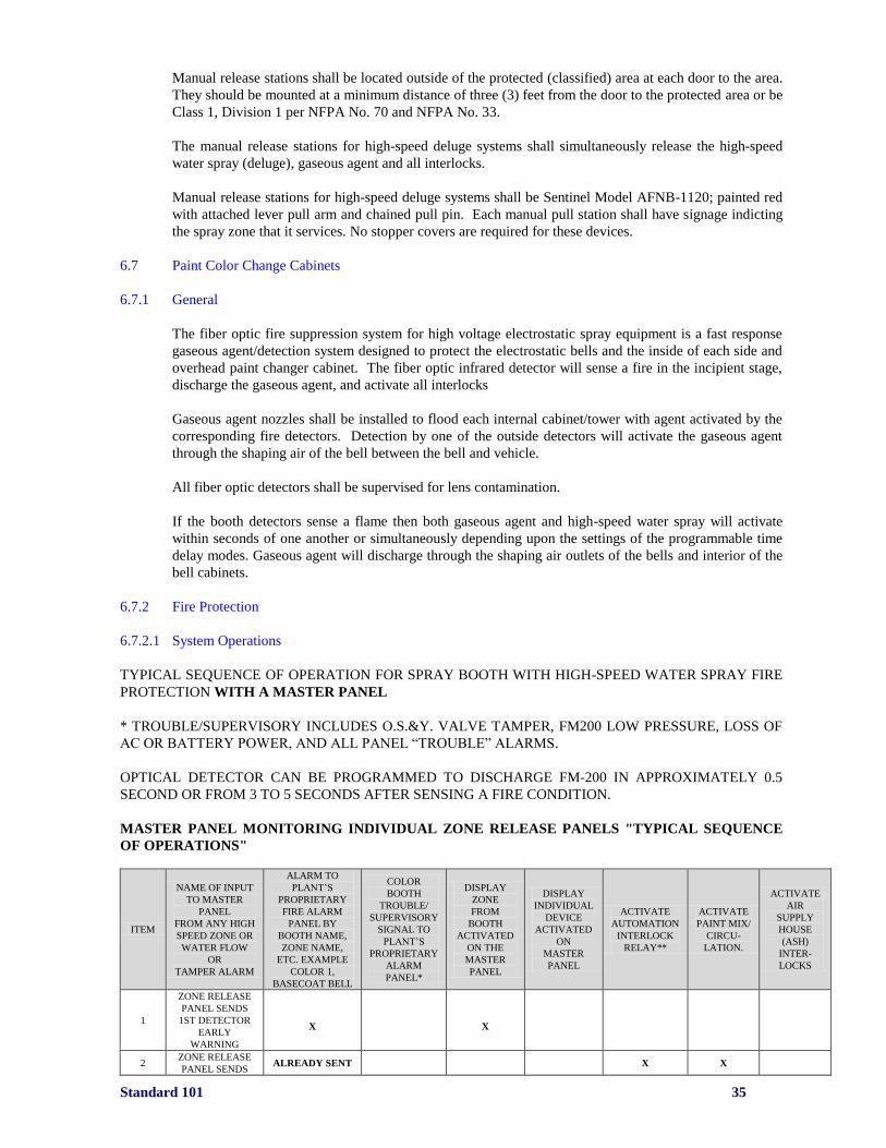
Standard 101 35
Manual release stations shall be located outside of the protected (classified) area at each door to the area.
They should be mounted at a minimum distance of three (3) feet from the door to the protected area or be
Class 1, Division 1 per NFPA No. 70 and NFPA No. 33.
The manual release stations for high-speed deluge systems shall simultaneously release the high-speed
water spray (deluge), gaseous agent and all interlocks.
Manual release stations for high-speed deluge systems shall be Sentinel Model AFNB-1120; painted red
with attached lever pull arm and chained pull pin. Each manual pull station shall have signage indicting
the spray zone that it services. No stopper covers are required for these devices.
6.7 Paint Color Change Cabinets
6.7.1 General
The fiber optic fire suppression system for high voltage electrostatic spray equipment is a fast response
gaseous agent/detection system designed to protect the electrostatic bells and the inside of each side and
overhead paint changer cabinet. The fiber optic infrared detector will sense a fire in the incipient stage,
discharge the gaseous agent, and activate all interlocks
Gaseous agent nozzles shall be installed to flood each internal cabinet/tower with agent activated by the
corresponding fire detectors. Detection by one of the outside detectors will activate the gaseous agent
through the shaping air of the bell between the bell and vehicle.
All fiber optic detectors shall be supervised for lens contamination.
If the booth detectors sense a flame then both gaseous agent and high-speed water spray will activate
within seconds of one another or simultaneously depending upon the settings of the programmable time
delay modes. Gaseous agent will discharge through the shaping air outlets of the bells and interior of the
bell cabinets.
6.7.2 Fire Protection
6.7.2.1 System Operations
TYPICAL SEQUENCE OF OPERATION FOR SPRAY BOOTH WITH HIGH-SPEED WATER SPRAY FIRE
PROTECTION WITH A MASTER PANEL
* TROUBLE/SUPERVISORY INCLUDES O.S.&Y. VALVE TAMPER, FM200 LOW PRESSURE, LOSS OF
AC OR BATTERY POWER, AND ALL PANEL “TROUBLE” ALARMS.
OPTICAL DETECTOR CAN BE PROGRAMMED TO DISCHARGE FM-200 IN APPROXIMATELY 0.5
SECOND OR FROM 3 TO 5 SECONDS AFTER SENSING A FIRE CONDITION.
MASTER PANEL MONITORING INDIVIDUAL ZONE RELEASE PANELS "TYPICAL SEQUENCE
OF OPERATIONS"
ITEM
NAME OF INPUT
TO MASTER
PANEL
FROM ANY HIGH
SPEED ZONE OR
WATER FLOW
OR
TAMPER ALARM
ALARM TO
PLANT’S
PROPRIETARY
FIRE ALARM
PANEL BY
BOOTH NAME,
ZONE NAME,
ETC. EXAMPLE
COLOR 1,
BASECOAT BELL
COLOR
BOOTH
TROUBLE/
SUPERVISORY
SIGNAL TO
PLANT’S
PROPRIETARY
ALARM
PANEL*
DISPLAY
ZONE
FROM
BOOTH
ACTIVATED
ON THE
MASTER
PANEL
DISPLAY
INDIVIDUAL
DEVICE
ACTIVATED
ON
MASTER
PANEL
ACTIVATE
AUTOMATION
INTERLOCK
RELAY**
ACTIVATE
PAINT MIX/
CIRCU-
LATION.
ACTIVATE
AIR
SUPPLY
HOUSE
(ASH)
INTER-
LOCKS
1
ZONE RELEASE
PANEL SENDS
1ST DETECTOR
EARLY
WARNING
X
X
2 ZONE RELEASE
PANEL SENDS ALREADY SENT X X

Standard 101 36
2ND DETECTOR
EARLY
WARNING
3
ANY 2 SENSORS
IN ALARM OR A
MANUAL
RELEASE
ALREADY SENT
X
X
4
TROUBLE/
SUPV.
FROM ZONE
RELEASE
PANEL
X
5
SPRINKLER
WATER FLOW
***
X
6
BOOTH WET
SPRINKLER
FLOW ***
X
X
X
X
7
BOOTH WET
SPRINKLER
VALVE CLOSED
VALVE
LOCKED
OPEN
VALVE
LOCKED
OPEN
* When a booth High-Speed Water Spray zone reports trouble to the Master Panel, it will be necessary for Plant Security to go
directly to the zone panel to determine what the exact trouble is.
** For an early warning, it is only required to shut off the paint & conveyors at the Automation Equipment Controller.
*** In the case of a sprinkler water flow or devices from areas other than High-Speed Water Spray panels, the name of the
actual device will be displayed i.e., Color 1 wet flow.
NOTE: IF EAGLE QUANTUM SYSTEM IS USED WITH A HOT BACK UP THEN THE EAGLE
QUANTUM WOULD BECOME THE MASTER PANEL AS WELL AS THE RELEASE PANEL AND
THE SEQUENCE WOULD NEED TO BE REVIEWED BY CORPORATE AND GRC.

Standard 101 37
TYPICAL SEQUENCE OF OPERATION FOR SPRAY BOOTH WITH HIGH SPEED WATER SPRAY
FIRE PROTECTION WITHOUT A MASTER PANEL
No.
SPRAY BOOTH
SPECIAL FIRE
SYSTEM
DEVICE
ACTIVATED
SEND
ALARM
SIGNAL
TO
PLANT’S
PROPRIETARY
ALARM
PANEL
SEND
PANEL
FAULT TO
PLANT’S
PROPRIE-
TARY
FIRE
ALARM
PANEL
ACTIVATE
HIGH
SPEED
WATER
SYSTEM
(DELUGE)
INTERLOCK
AUTOMATION
&
CONVEYORS,
STOP PAINT
FLOW via
AUTOMATION
INTERLOCK
PAINT MIX
ROOM &
ALL CIRCU-
LATION
PUMPS
ACTIVATE
FM200
SYSTEM
IN
SAME
GROUP
OF BELLS
AS
DETECTOR
ZONE OR
ALL BELLS
IF MANUAL
RELEASE IS
OPERATED
1
FIRST
DETECTOR
EARLY
WARNING
X
2
SECOND
DETECTOR
EARLY
WARNING
ALREADY
SENT X X X
3
TWO
DETECTORS
SEE FIRE >5
SECONDS OR
MANUAL
RELEASE
ACTIVATED
ALREADY
SENT
X
X
X
ALREADY
SENT
4
FIBER OPTIC
DETECTOR
IN ALARM
X
X
X
X
5
TROUBLE/
SUPER-VISORY
AT SYSTEM
PANEL*
X
NOTE: IF A MASTER PANEL IS NOT USED, A LISTED CONTROL PANEL OF SAME MANUFACTURER AS
THE HIGH-SPEED WATER SPRAY SYSTEM MUST MONITOR BOOTH SPRINKLERS. FOR THE PURPOSE
OF INTERLOCKS, EACH FLOW SWITCH MUST ALSO BE MONITORED AT THE PLANT'S PROPRIETARY
FIRE ALARM PANEL.
6.7.2.2 Releasing Control Panel
General Description:
Release Control Panels (RCP) are utilized to control the release of fire suppression agent such as HFC-
227ea (FM-200), carbon dioxide, dry chemical, high-speed deluge, etc. NOTE: Since these panels can
be used to activate a fire alarm, the manufacturer commonly refers to these as Fire Alarm Control Panels
(FACP).When used to release a fire suppression agent as well as activate a fire alarm, refer to the given
panel as a Release Control Panel (RCP) and the panel used to activate the building fire alarm
(evacuation) system as the Fire Alarm Control Panel. At a given facility, several RCPs may be connected
to one FACP.
RCP'S are only one component of the entire fire suppression system. The name of the given panel or the
manufacturer is generally used to describe the entire system. It takes several devices/components to
makeup a fixed fire suppression (protection) system. These include such devices as manual release
stations, smoke detectors, heat detectors, flame detector, strobes, horns, speakers, modules, relays, cable,
conduit, extinguishing agent, cylinders, tanks, batteries, etc.
The Release Control Panel is located within a large cabinet that also contains various relays, modules,
switches, batteries, power supply, battery charger, wiring, etc.
The Release Control Panel contains the CPU (microprocessor). Addressable Release Control Panels
have a keypad that can be used to program the panel.
RCP'S contains relays and terminal blocks used to attach wires connected to the power supply,
Notification Alarm Circuits (NAC), Initiating Device Circuits (IDC), and Signaling Line Circuit(s), etc.
Standard 101 38
RCP'S provide I/O for specific action due to detection of an off normal condition. It stores all the
system’s operational parameters (programmed) in non-volatile memory (different from the history
memory (buffer)). RCP'S contains the real time clock for the date and time used to stamp event history.
Addressable Release Control Panel: A Release Control Panel that has the ability to display the
programmed address (name) of the device or devices that have been activated due to a fire condition,
manual action, or electrical “short” or “open”, etc. Each device associated with the system is assigned an
address (name) which when programmed correctly is identified by the microprocessor of the RCP.
Should an alarm or trouble condition occur, the assigned address of the device is known rather than just a
zone that contains multiple devices. NOTE: Devices connected to an addressable RCP must be approved
for use with that panel. A conventional device will not work on an addressable RCP.
All electrical conduit/penetrations shall enter fire release control enclosures from the side of
enclosure only.
All penetrations and terminations made to the fire release control enclosure shall be made or
supervised by the supplier of the fire release panel and enclosure.
Solid wires shall not be permitted regardless of gauge size.
A smoke detector is not required over the release control panel as Corporate has determined that this
panel is not part of the building fire alarm system. However, if the AHJ requires this detector, then it
shall be wired (separate address) to the building fire alarm system, and not the release control panel.
6.7.2.3 Contractor Qualifications
The contractor for fire detection/suppression system installation shall be a factory trained and authorized
distributor of the specified products.
The contractor shall be able to provide proof of the following available services if requested:
- Provide twenty-four (24/7) emergency service contacts
- Maintain a fill station for refill of all gaseous agents utilized at Chrysler LLC
- Employment of factory trained personnel
- Adequate supply of spare parts to provide emergency service of the system within eight (8)
hours.
- Experienced in the installation of automotive spray booth special hazard fire extinguishing
systems.
6.7.2.4 Spray Booth Hydrocarbon Detectors
Hydrocarbon detectors are required in the return air plenums for any spray booth zone(s) that recirculates
solvent laden air. These detectors must be the infrared type, be compatible and connected to the Eagle
Quantum Premier (EQP) control panel. These detectors shall be model number PIRECLA4A2W1;
Pointwatch Eclipse IR gas detector for the EQP panel.
These detectors shall be installed by the spray booth fire protection integrator. The detector quantities
and locations shall be determined by consultation with the spray booth/ ventilation supplier.
The detectors shall provide alarm points for low, high and fault condition in the form of a dry contact at
the EQP panel. The low alarm point (20%) LEL shall send an alarm to the building fire alarm system.
The high alarm point (40%) LEL shall cause the booth ventilation system to go to 100% outside fresh air
and stop all painting applicators in the affected zone.

Standard 101 39
7.0 Painting Operations
7.1 Paint Rooms/Booths
Sprinkler protection shall be provided throughout all Paint Rooms/Booths. This includes but is not
limited to all robot X-rail enclosures and paint line stations (dog-house) unless designed so that any paint
or solvent discharge will flow into the water-wash area of the spray booth.
Sprinkler design density shall be 0.30 GPM (gallons per minute) per square foot over the most remote
4,000 square feet.
Sprinkler heads shall be of the fusible link type and have a 286°F temperature rating. NOTE: “Flash-off”
tunnels (located prior to painted bodies entering ovens) shall have 500°F sprinkler heads.
7.2 Clean Room - Paint Shop
Sprinkler protection shall be provided throughout Paint Shop Clean Rooms.
Sprinkler design density shall be 0.30 GPM per square foot over the most remote 4,000 square feet.
Sprinkler heads shall be of the fusible link type and have a 286°F temperature rating.
7.3 Paint Mix Rooms
Fire protection for paint mix rooms shall be automatic wet pipe sprinklers and gaseous agent (main
cylinder only). Sprinkler design shall be 0.60 GPM per square foot over the most remote 4,000 square
feet or the entire room if less than 4,000 square feet. ). Paint mix room sprinkler system shall be fed from
their own riser. No other sub-risers shall be tapped off the riser designated for the paint mix room.
Sprinkler heads shall be fusible link type having a minimum nominal K-factor of 8.0 and temperature
rating 286°F.
Gas agent shall be designed for a minimum 9.8% concentration of HFC-227ea (FM-200). For HFC-125
(ECARO) the minimum design concentration is 12.2%.
Multi-spectrum detectors (same manufacturer as those utilized in paint booths) shall be installed to
release the gaseous agent. Quantities shall be approved by Corporate Fire Engineer & GRC.
Low level mechanical ventilation shall be interlocked with the gaseous agent system. A sail switch or
other means of monitoring the air flow shall be provided. The sail switch shall be monitored locally.
Paint mix rooms shall have a minimum of two (2) means of egress, preferably on opposite sides of the
room.
All equipment within the rooms shall be electrically grounded per NFPA No. 77, “Static Electricity”.
Electrical components and wiring circuits shall meet the hazardous requirements for Class 1, Division 1
locations as set forth in NFPA No. 70, “National Electric Code”.
All dispensing from drums shall use an approved drum pump or “dead-man” type of dispenser. All types
of dispensers/pumps shall be properly grounded utilizing an approved Chrysler LLC clamp.
Curbs/ramps shall be provided to contain flammable liquid spills in accordance with the applicable
codes. Refer to Section 5.4.3 for drainage requirements.

Standard 101 40
7.4 Paint Pots Located Outside of Paint Mix Rooms
Sprinkler protection shall be provided throughout areas with paint pots. These pots shall be limited to 30
gallons each.
Sprinkler design density shall be 0.30 GPM per square foot over the most remote 4,000 square feet.
Sprinkler heads shall be of the fusible link type and have a 286°F temperature rating.
Paint pots shall be located within a one-hour fire rated enclosure and in accordance with applicable local
codes. NOTE: If paint pots are not located within a one-hour fire rated enclosure, the Corporate Fire
Prevention Engineer and GRC must be notified and approval obtained.
Where air operated paint pots are used, water flow alarms shall be interlocked with the air supply to shut-
off the air-operated paint pots upon sprinkler system water flow.
7.5 Flammable Liquid Storage Rooms
Flammable liquid storage rooms shall have sprinkler protection and gaseous agent protection (main
cylinder(s) only). Gas agent shall be designed for a minimum 9.8% concentration of HFC-227ea (FM-
200). For HFC-125 (ECARO) the minimum design concentration is 12.2%.
Sprinkler design shall be 0.60 GPM per square foot over the most remote 4,000 square feet or the entire
room if less than 4,000 square feet.
Sprinkler heads shall be fusible link type having a minimum nominal K-factor of 8.0 and temperature
rating 286°F.
Additional sprinkler protection shall be provided under all elevated tote storage racks supplying the mix
room.
Roller platforms shall be a maximum of three (3) tiers high with drum storage “on side”. Drum or pallet
storage shall be stored a maximum of one (1) high stored “on end”.
There shall be no dispensing of flammable liquids within the rooms.
Curbs/Ramps shall be provided to contain flammable liquid spills in accordance with the applicable
codes. Refer to Section 5.4.3 for drainage requirements.
All electrical components and wiring circuits shall meet the hazardous requirements for Class 1, Division
2, Group D locations as set forth in NFPA No. 70, “National Electric Code”.
Multi-spectrum detectors (same manufacturer as those utilized in paint booths) shall be installed to
release the gaseous agent. Quantities shall be approved by Corporate & GRC.
Low level mechanical ventilation shall be interlocked with the gaseous agent system. A sail switch or
other means of monitoring the air flow shall be provided. The sail switch shall be monitored locally.
Paint storage rooms shall have a minimum of two (2) means of egress, preferably on opposite sides of the
room.

Standard 101 41
7.6 Computer Control Room for Paint Mix Rooms
Fire protection for the Paint Mix Computer Control Room shall consist of sprinklers and gaseous agent
(main cylinder(s)). Gaseous agent designed for minimum 7.0% concentration of HFC-227ea (FM-200).
For HFC-125 (ECARO) the minimum design concentration is 8.0%.
Sprinkler design shall be 0.30 GPM per square foot over the most remote 4,000 square feet or the entire
room if less than 4,000 square feet.
Sprinkler heads shall be fusible link type and rated 286F.
In areas where raised floors are used, under floor spaces shall be protected with gaseous agent in rooms
where above floor agent protection is provided.
Detection shall be by addressable smoke detectors.
7.7 Paint Laboratories
Sprinkler protection shall be provided throughout Paint Laboratories and in paint spray exhaust hood and
exhaust stack.
Sprinkler design density shall be 0.60 GPM per square foot over the most remote 4,000 square feet or the
entire laboratory if less than 4,000 square feet.
Sprinkler heads shall be of the fusible link type having a minimum nominal K-factor of 8.0 and shall
have a 286°F temperature rating.
7.8 Paint Sludge Rooms
Sprinkler protection shall be provided throughout and under all sludge bins.
Sprinkler design density shall be 0.60 GPM per square foot over the most remote 4,000 square feet.
Sprinkler heads shall be of the fusible link type having a minimum nominal K-factor of 8.0 and shall
have a 286°F temperature rating.
Fire hose stations shall be provided throughout (if required by the local AHJ).
If a sludge dryer system is provided then special protection may be required.
7.9 Paint Drying Oven & Uniprime Drying Oven (Dipped)
If all the following conditions are met, then sprinkler protection shall be eliminated unless required by
the local AHJ:
- Ovens are welded seam type construction
- Indirect fired heating system. Direct-fired may be utilized after discussion with Corporate Fire
and Global Risk Consultants
- No plastic (larger than gasoline fill cap) parts attached to vehicles or mounted
on conveyor
- No “body” covers or masking paper or tape
- No paint residue build-up on walls or floor
- Gas-trains shall be reviewed and approved by HPR insurance carrier
Sprinklers shall not be required in paint oven exhaust ducts when sprinklers are not provided in the oven.
Ovens shall be inspected at least annually by local G4S Security for paint residue with records of
inspections maintained on file for review. Ovens shall be shut down before entering for at least 24 hours.
The Chrysler lockout/tag out system shall be followed.

Standard 101 42
If sprinkler protection is required, it shall be a “dry” pipe system and be designed as follows:
1). Sprinkler design density of 0.30 GPM per square foot over the most remote 4,000 square feet.
2). Drain piping shall be piped to exterior of ovens and, if feasible, connected to nearest drain.
3). Piping shall not be located above the vehicle’s conveyor path for control of dirt.
4). All condensate drains shall have a drum drip installed with a normally open globe or ball valve
installed at the top and a normally closed globe or ball valve installed at the bottom of the drum.
NOTE: Galvanized pipe shall not be used within oven.
Use table below for sprinkler temperature rating
Oven Type Oven Temperature Temperature Rating of Sprinkler
Uniprime 350°F 500°F
Low Bake 190°F 360°F
All Others 250°F 360°F
For oven temperatures that vary from the above list, contact Corporate Fire Engineer and GRC.
7.10 Paint Conveyor Control Rooms
Fire protection for the Paint Conveyor Control Rooms shall consist of sprinklers and gaseous agent (main
tank/cylinder only). Gaseous agent designed for minimum 7.2% concentration of HFC-227ea (FM-200).
For HFC-125 (ECARO) the minimum design concentration is 8.0%.
Sprinkler design density shall be 0.30 GPM per square foot over the most remote 4,000 square feet or the
entire room if less 4,000 square feet.
Sprinkler heads shall have a 286°F temperature rating.
In areas where raised floors are used, under floor spaces shall be protected with gaseous agent in rooms
where above floor agent protection is provided.
Detection shall be by addressable smoke detectors.
7.11 Paint Uniprime Dip Enclosures (E-coat)
No fire protection is required for these enclosures as long as construction of the entire enclosure is non-
combustible.
7.12 Paint Uniprime Drying Ovens
Refer to Section 7.9
7.13 Paint Uniprime Control Room
Sprinkler protection shall be provided throughout.
Sprinkler design density shall be 0.30 GPM per square foot over the most remote 4,000 square feet or the
entire room is less than 4,000 square feet.
Sprinkler heads shall be of the fusible link type having a minimum nominal K-factor of 5.6 and shall
have a 286°F temperature rating.
In areas where raised floors are used, under floor protection in the form of a gaseous agent shall be
provided. Gaseous agent designed for minimum 7.0% concentration of HFC-227ea (FM-200). For HFC-
125 (ECARO) the minimum design concentration is 8.0%.
Detection shall be addressable smoke detectors.

Standard 101 43
7.14 Additional Areas
Stairways that are four feet wide or wider shall have sprinkler protection installed below/ underneath in
accordance with this Standard. Sprinklers shall be approved intermediate type.
If combustible materials are stored beneath open grating floor areas and conveyor guards, sprinkler
protection shall be installed below/underneath. An alternative would be to provide a non-combustible
perimeter barrier around the entire area. NOTE: This may require a variance from the local AHJ.
Sprinkler protection shall be installed underneath insulated paint supply lines that are separated by less
than two (2) inches and are in bundles greater than four (4) feet wide.
Standard 101 44
8.0 Shut-down Sequence of Equipment
8.1 Spray Booth Main Sprinkler Waterflow Signal
When the spray booth main header flow switch feeding the booth plenum and interior signals in a
waterflow in the spray booth the following sequence shall take place:
1. Plant’s proprietary fire alarm system sends signal to security
2. Paint circulation system shutdown
3. Paint automatic zone equipment shutdown
4. Conveyor system shutdown
5. Heated flash I/R (infrared) shutdown
8.2 Spray Booth High Speed Waterflow Signal
When the spray booth high-speed flow switch feeding the booth’s Cla-Valves signals a waterflow in the
spray booth, the following sequence shall take place:
1. Plant’s proprietary fire alarm system sends signal to security
2. Paint circulation system shutdown
3. Paint automatic zone equipment shutdown
4. Conveyor system shutdown
5. Heated flash I/R (infrared) shutdown
8.3 Spray Booth Air Supply House Waterflow Signal
When the spray booth air supply house flow switch feeding the house or ductwork signals a waterflow in
the air supply house system, the following sequence shall take place:
1. Plant’s proprietary fire alarm system sends signal to Security
2. Paint circulation system remains “on”
3. Paint automatic zone equipment remains “on”
4. Conveyor system remains “on”
5 Air supply house in alarm shutdown
6. Except for the affected ASH, spray booth supply and exhaust fans remain “on
8.4 Spray Booth Eliminator Tank Water flow Signal {if sprinkler protection is required)
When the spray booth eliminator flow switch in the eliminator section signals, the following sequence
shall take place:
1. Water flow switch sends signal to Security
2. Paint circulation system remains “on”
3. Paint automatic zone equipment remain “on”
4. Conveyor system remains “on”
5 Air supply houses remain “on”
6. Spray booth supply and exhaust fans remain “on”
7. Heated flash I/R (infrared) remains “on”
8. Clean room air supply remains “on”.
8.5 Paint Shop Clean Room Water flow Signal
When the paint shop clean room flow switch in the clean room area signals, the following sequence shall
take place:
1. Plant’s proprietary fire alarm system sends signal to Security
2. Paint circulation system remains “on”
3. Paint automatic zone equipment remains “on”

Standard 101 45
4. Conveyor system remains “on”
5. Air supply houses remain “on”
6. Spray booth supply and exhaust fans remain “on”
7. Heated flash I/R (infrared) remain “on”
8. Clean room air- supply remains “on”.

Standard 101 46
9.0 Water Borne Paint Systems
9.1 Detector Types
Protect the same as solvent paint zones.
9.2 High-Speed Water Spray (Deluge) Systems
A high-speed Water Spray (deluge) System is required for all electrostatic water borne paint zones.
Details of the system are the same as for solvent zones.
9.3 Gaseous Agent System
An HFC-227ea (FM-200) system is required with the same design parameters as is used with solvent
based paint systems.
9.4 Interlocks/Approved Hand Guns
Refer to Section 8.2
NOTE: The 10-kv AccuCharge spray guns manufactured by Accuspray have been approved by
Corporate for use in paint zones without a high-speed water (deluge) system. Normal booth sprinklers
must be provided and in service at all times. Other pre-approved spray guns are the Graco Pro 3500 SC,
Pro Xs2, Xs3, Xs4 and the Nordson ISO-Flow spray guns, and REA IV electrostatic hand gun from
ITW-Ransburg. Per NFPA #33, optical flame detectors are required in all electrostatic zones to shut off
the paint supply.
The above approved manual spray hand guns may be used for solvent or waterborne applications without
the need for high-speed water spray.

Standard 101 47
10.0 POWDER ANTICHIP APPLICATIONS
10.1 Detection and Suppression - General Requirements
Provide double interlock pre-action sprinkler system, optical flame detection and HFC-227ea (FM-200)
gaseous agent suppression systems for powder application areas. Pre-action sprinkler systems are
required in all application areas. Gaseous agent is required in automation zones through the shaping air.
Detection is common for the gaseous agent and preaction systems. The Eagle Quantum system shall
control the discharge of the preaction and gaseous agent.
10.1.1 Detection
Provide multi-spectrum IR detectors.
Detection shall be installed to view all automation equipment with the detector cone of vision
overlapping to observe the entire booth’s floor areas.
The control rooms and equipment storage areas shall be provided with wet pipe automatic sprinkler
protection.
The powder coat booth shall be provided with a double interlocked pre-action sprinkler system. The
same release control panel used in the powder booth for the detection system shall also activate the pre-
action system.
10.1.2 Fire Suppression
When the fire detection signals that a “fire” condition has occurred, an HFC-227ea (FM-200)
suppression system shall activate through the gun’s shaping air or an external discharge nozzle mounted
on the automation equipment. The system shall be set-up so that each group of side bells or overhead
bells discharges individually. Discharge time shall be for a minimum of ten (10) seconds.
Hand-held electrostatic zones shall not be protected with HFC-227ea (FM-200). Detection shall be
provided to shutdown the power to guns, powder supply, supply and exhaust air, and conveyor systems.
Pre-action protection shall be designed for a 0.30 gpm per square foot design density.
The powder system/booth supplier shall ensure that the powder concentration is maintained at all times
(including upset conditions) below 50% of the MEC (minimum explosive concentration) or explosion
protection is required.
10.2 Electrical Classifications
1. Spray booth interior is Class 2, Division 1 as defined in NFPA No. 70, “National Electric
Code”.
2. All electric devices which are classified as Class 2, Division 2 must have a tag or other
indicating method on the device/part in question.
3. All spray booth lighting fixtures shall be rated Class 2, Division 1 if the lighting tubes can be
accessed from inside the booth.
4. All spray booth lighting fixtures shall be rated Class 2, Division 2 if the lighting tubes only have
access from outside the booth enclosure.
5. All electrical devices within three (3) feet of a booth’s interior shall be rated Class 2, Division
1.This includes man doors, silhouettes, etc.
6. If the HEPA filter is breached, the spray booth must shut down by use of a differential pressure
switch.
7. Ductwork interior to the HEPA filter shall be Class 2, Division 1.
8. Ductwork after the HEPA filter is non-classified.
Standard 101 48
9. The powder storage room shall be Class 2, Division 2.
10. All control panels, and other enclosures which are air purged, shall follow the requirements of
NFPA for air purge systems. This eliminates the need for classified electric circuits and
equipment.
11. Explosion relief panels are required for the powder room unless the installing contractor can
guarantee that the powder concentration is maintained below 50% of the MEC (including upset
conditions).
12. All feed hopper rooms shall be Class 2, Division 2.
13. Internal to all air supply houses shall be non-classified unless the air is re-circulated. If re-
circulated, the first section of the house shall be Class 2, Division 2.
14. All automation enclosures, where the powder is not supplied within tubing in conduit, shall be
purged or provided with Class 2 Division 2 electric circuits.
15. Electrical interlocks shall be provided to shutdown all electrostatic power, power feed,
conveyors, and automation power.

Standard 101 49
11.0 Paint Auxiliary Recirculation Systems
11.1 General
The secondary paint recirculation system uses a pumping station located close to the main spray booths
in the paint shops. These systems can be used for both solvent and water borne paints. The pumps and
ancillary equipment are usually located on a pre-fabricated skid.
11.2 Construction
A two- (2) hour rated enclosure shall be provided around the secondary module with appropriate fire
doors for all openings.
Two (2) means of egress shall be provided for the room.
On new paint shops, floor drainage within the room shall be provided to handle the sprinkler water
discharge for ten minutes. For existing paint shops, provide a dike at all openings, sized to contain the
sprinkler water discharge for ten minutes.
All electrical components within the enclosure shall be rated for Class 1, Division 2, Group D locations.
Provide continuous low level mechanical ventilation designed for one (1) cfm per square foot of floor
area but less than 150-cfm. An air flow switch or similar device shall be provided such that if the
ventilation system is not operating, an alarm is sounded both locally and at the local Plant’s proprietary
fire alarm panel/system.
For solvent-based systems only, provide explosion relief venting through the ceiling designed at a ratio of
1:50. The relief pressure shall be 20-25 psf. The walls shall be designed for a blast resistance of 100-
125 psf. If explosion venting is not practical, then a secondary “high level” ventilation system shall be
installed and capable of providing twelve (12) air changes per hour. This method shall not be utilized
without consulting Chrysler Security Services and GRC. This system shall use a vapor detection system
to start the high-level ventilation system at 25% of the L.E.L. In addition, it shall discharge the gaseous
fire suppression agent at 50% L.E.L. L.E.L. means the Lower Explosive Limit of the given solvent.

Standard 101 50
12.0 SEQUENCE OF OPERATIONS/PLAN REVIEW/ACCEPTANCE TESTING
Also see charts in section 6.7.2
12.0 Sequence of Operations/Plan Review/Acceptance Testing of Completed Systems
PLAN REVIEW -SUBMISSION REQUIREMENTS: (in English)
Floor Plan of entire project drawn to scale.
Location of alarm-initiating and notification appliances.
Alarm control and troubling signaling equipment.
Annunciation.
Power Connection.
Battery Calculations.
Voltage-drop calculations.
Conductor type and sizes.
Manufacturers, model numbers and listing information for equipment, devices and materials.
Details of ceiling heights and construction.
The interface of the fire safety control functions.
Directional north orientation.
Identify of each room/area.
Sequence of Operations/Matrix.
SEQUENCE OF OPERATIONS: BASED UPON SEQUENTIAL ZONING
PAINT MIX COMPUTER CONTROL ROOM:
ADDRESSABLE IONIZATION SMOKE DETECTORS -
1) Detection of a fire condition by any smoke detector shall activate the associated audible/visual “Trouble”
alarm signals on the Release Control Panel, Building Fire Alarm Panel and signaling devices within the room.
No activation of the gas fire suppression agent or interlocks.
2) Continued detection of a fire condition by any second smoke detector shall activate the associated
audible/visual “Fire” alarm signals on the Release Control Panel, Building Fire Alarm Panel and signaling
devices within the room. Also, activation of the gas agent fire suppression agent (HFC-227ea) and activation
of the interlocks. Interlocks include the shutdown of all ventilation, closing of any required dampers,
shutdown of electric power to control panel/computer equipment and closing of any required interlocked fire
doors.
MANUAL PULL STATION –
1) Activation of any manual pull station will:
A. Activate audible and visual “Fire” alarm signal on the Release Control Panel and Building Fire Alarm
Panel.
B. Discharge of the gas fire suppression agent – HFC-227ea.
C. Activate all interlocks for the given room.
High-Speed Deluge Water Spray Nozzle Pattern Verification
BETE NOZZLES DISCHARGE PATTERN
1) Discharge high-speed deluge system using a manual pull station.
2) Make a visual observation of water discharge from all Bete nozzles.
3) Make a visual observation of all areas within the spray booth looking for any gaps in the water spray
discharge.
4) Turn-off system and make any necessary modifications to the Bete nozzle(s) and/or piping.
5) Re-test system as necessary.

Standard 101 51
TESTING OF EACH OPTICAL FLAME DETECTOR FOR “TROUBLE ALARM” MODE
1) If Bete nozzle discharge and test pattern have been tested and acceptable, install a down-commer securely on
each Bete nozzle.
2) Using an approved test lamp (or methods applicable to the detector) for the optical flame detector, operate
test device for each detector per the manufacturers’ specification.
3) Within one-half second but less than three seconds, the “Trouble” alarm (audible/visual) should activate on
the Release Control Panel and Building Fire Alarm Panel.
TESTING OF EACH OPTICAL FLAME DETECTOR FOR “FIRE ALARM” MODE
1) If Bete nozzle discharge and test pattern have been tested and acceptable, install a down-commer securely on
each Bete nozzle.
2) Using an approved test lamp (or methods applicable to the detector) for the optical flame detector, operate
test lamp (or methods applicable to the detector) each detector per the manufacturers’ specification.
3) Within one-half second but less than three seconds, the “Trouble” alarm (audible/visual) signal should
activate on the Release Control Panel and Building Fire Alarm Panel and then you have two options.
A. Quickly move test lamp (or use a second test lamp) to another detector and operate test lamp in front of
second detector before first detector unlatches (re-sets) or
B. Continue to hold test lamp in front of first detector.
4) Regardless, in approximately 5 seconds the “Fire” alarm (audible/visual) signal should activate on the
Release Control Panel and Building Fire Alarm Panel, the high-speed (deluge) water spray system discharge,
and interlocks activate. Interlocks include power to automation (robots), conveyor shutdown, and power to
paint mixers (paint re-circulation system).
5) Repeat tests until all optical flame detectors have been tested and are acceptable.
TESTING OF EACH MANUAL PULL STATION
1) If Bete nozzle discharge and test pattern have been tested and acceptable, install a down-commer securely on
each Bete nozzle.
2) Manually operate a manual pull station.
3) Almost immediately the high-speed (deluge) water spray system should discharge.
4) Reset system and repeat test using other manual pull station or stations.
TESTING OF EACH SELECTOR (BY-PASS) SWITCH
1) A.C. Power switch – turn switch to “off” position and power “on” light should not be lit, audible and visual
“Trouble” alarm signal on Release Control Panel should activate, battery power light should be lit and check
loss of A. C. power to Release Control Panel using a multimeter. Also, test should be made by leaving switch
in “on” position and disconnect one side of the A. C. power supply and determine if panel automatically
switches over to battery power.
2) Battery Power switch – turn switch to “off” position and battery power light should not be lit, audible and
visual “Trouble” alarm signal on Release Control panel should activate. Also, disconnect a connection on a
battery and determine if Release Control Panel does same sequence.
3) High-speed (deluge) water spray switch – turn switch to “off” position. Audible and visual “Trouble” alarm
signal on Release Control Panel should activate. Also, using a test lamp on an optical flame detector and hold
for five seconds or longer to determine if the “Fire” alarm signal and the interlock activate.
4) Interlock switch – turn switch to “off” position and audible and visual “Trouble” alarm signal on Release
Control Panel should activate. Also, using a test lamp (or methods applicable to the detector) on an optical
flame detector and hold for five seconds or longer to determine if the “Fire” alarm signal and the interlock do
not activate. NOTE: Turn off high-speed (deluge) water spray switch also or system could discharge or use
down commers.
Standard 101 52
ELECTROSTATIC SPRAY PAINT BOOTHS WITH CLEANWALL CABINETS and BELLS (HFC-
227ea (FM-200) in the clean wall cabinets and through the shaping air and high-speed (deluge) water spray
in the spray painting zone)
These zones have optical flame detectors within the spray-painting zone and one at the top of each clean wall
cabinet. Also, each bell enclosure and overhead bell assembly has the fiber optic flame detectors.
For the optical flame detectors in the spray painting bell zone (booth):
1). Since Bete nozzles were already positioned and the water discharge pattern accepted, down commers (plastic
tubes) can be firmly attached to the Bete nozzle and arranged to discharge water into the water wash area of the
booth.
2). If the HFC-227ea (FM-200) cylinders and initiator modules are wired (but not the actual initiators), the flash
bulbs are installed (like what was done for the Paint Mix Room). Each initiator for the given spray booth should
have a flash bulb installed.
3). Attach a nitrogen tank to each HFC-227ea (FM-200) discharge pipe to check shuttle valve operation.
4). The test flash bulb for each HFC-227ea (FM-200) cylinder should flash but the high-speed deluge should not
discharge), nitrogen should discharge through the shaping air orifice for each bell, the fire alarm (audio & visual)
should have activated and the interlocks activated (conveyor shut-down, power to bells and power to the paint
mixers).
5). The systems and interlocks should be reset and new flash light bulbs installed.
Fiber optic detectors located within the clean wall cabinets:
1). To be safe - since Bete nozzles were already positioned and the water discharge pattern accepted, down
commers (plastic tubes) can be firmly attached to the Bete nozzle and arranged to discharge water into the water
wash area of the booth.
2). If the HFC-227ea (FM-200) cylinders and initiator modules are wired (but not the actual initiators), the flash
bulbs are installed (like what was done for the Paint Mix Room). Each initiator for the given spray booth should
have a flash bulb installed.
3). Attach a nitrogen tank to each HFC-227ea (FM-200) discharge pipe to check shuttle valve operation.
4). The test flash bulb for each HFC-227ea (FM-200) cylinder should flash but the high-speed deluge should not
discharge), nitrogen should discharge through the shaping air orifice for each bell, the fire alarm (audio & visual)
should have activated and the interlocks activated (conveyor shut-down, power to bells and power to the paint
mixers).
5). The systems and interlocks should be reset and new flash light bulbs installed.

Standard 101 53
13.0 PLATFORMS
Platforms (solid and/or grated flooring):
Platforms that are 36-inches or higher above finished floor and wider than 48 inches shall be protected by one of
the following methods:
a) An approved skirting method around the perimeter that prevents any storage to be introduced below the
platform.
b) Automatic sprinkler protection designed to provide a minimum density of 0.30-gpm per square feet over
the most remote 4,000 square feet (or entire platform area) plus 500-gpm hose stream allowance for
platforms up to six-feet in height. Platforms six-feet and over in height shall have sprinkler protection
designed to provide a minimum density of 0.60-gpm per square feet over the most remote 4,000 square
feet (or entire platform area) plus 500-gpm hose stream allowance or as stated by the Corporate Fire
Prevention Engineer.
An approved skirting method shall be composed of one of the following:
a) Sheet metal panels attached around the perimeter by fasteners such as bolts, screws, clips, etc. Panels
shall be able to be removed for a visual inspection and cleaning of any debris that may collect in the area
below the platform.
b) Horizontal metal bars (such as Unistrut) or framework attached to the platform’s vertical supports and
spaced a maximum of 12-inches between horizontal metal bars. Metal bars shall be attached by a method
where access is available for cleaning any debris under the platform.
A process above the platform that involves flammable or combustible liquids requires automatic sprinkler
protection to be installed regardless of platform height.
Platforms less than 36-inches in height, not utilizing flammable or combustible liquids, shall be arranged for
visual management and cleaning but will not require skirting or automatic sprinkler protection unless required by
the local Authority Having Jurisdiction (AHJ).

Standard 101 54
14.0 Construction of Spray Booths
Walls, doors, and ceilings that enclose a spray booth shall be constructed of noncombustible materials and shall be
securely and rigidly mounted or fastened. The interior surfaces of the spray booth shall be smooth, designed and
installed to prevent pockets that can trap residues, and designed to facilitate ventilation and cleaning. The floor of
the spray area shall be constructed of noncombustible material.
Aluminum shall not be used for structural support members or the walls or ceiling of a spray booth. Aluminum
also shall not be used for ventilation ductwork associated with a spray booth. Aluminum shall be permitted to be
used for interior components, such as platforms, spray apparatus components, and other ancillary devices.
Panels for light fixtures or for observation shall be of heat-treated glass, laminated glass, wired glass, or
hammered wired glass and shall be sealed to confine vapors, mists, residues, dusts, and deposits to the spray area.
Panels for light fixtures shall be separated from the fixture to prevent the surface temperature of the panel from
exceeding 200°F. The vision panel frame and method of attachment shall be designed to not fail under fire
exposure before the vision panel fails. The light fixture shall be mounted outside the spray booth on the vision
panel.