Christopher Batten - Cornell UniversitySystem-Level Modeling with SystemC ECE 5745 T01: Hardware...
55
ECE 5745 Complex Digital ASIC Design Topic 1: Hardware Description Languages Christopher Batten School of Electrical and Computer Engineering Cornell University http://www.csl.cornell.edu/courses/ece5745
Transcript of Christopher Batten - Cornell UniversitySystem-Level Modeling with SystemC ECE 5745 T01: Hardware...
ECE 5745 Complex Digital ASIC DesignTopic 1: Hardware Description Languages
Christopher Batten
School of Electrical and Computer EngineeringCornell University
http://www.csl.cornell.edu/courses/ece5745
Evolution of HDLs HDLs Across Stack “High-Level” RTL Guarded-Atomic Actions System-Level Modeling
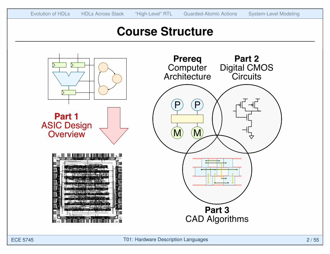
Course Structure
Part 1ASIC Design
Overview
Part 2Digital CMOS
Circuits
Part 3CAD Algorithms
P P
MM
PrereqComputer
Architecture
Part 1ASIC Design
Overview
ECE 5745 T01: Hardware Description Languages 2 / 55
Evolution of HDLs HDLs Across Stack “High-Level” RTL Guarded-Atomic Actions System-Level Modeling
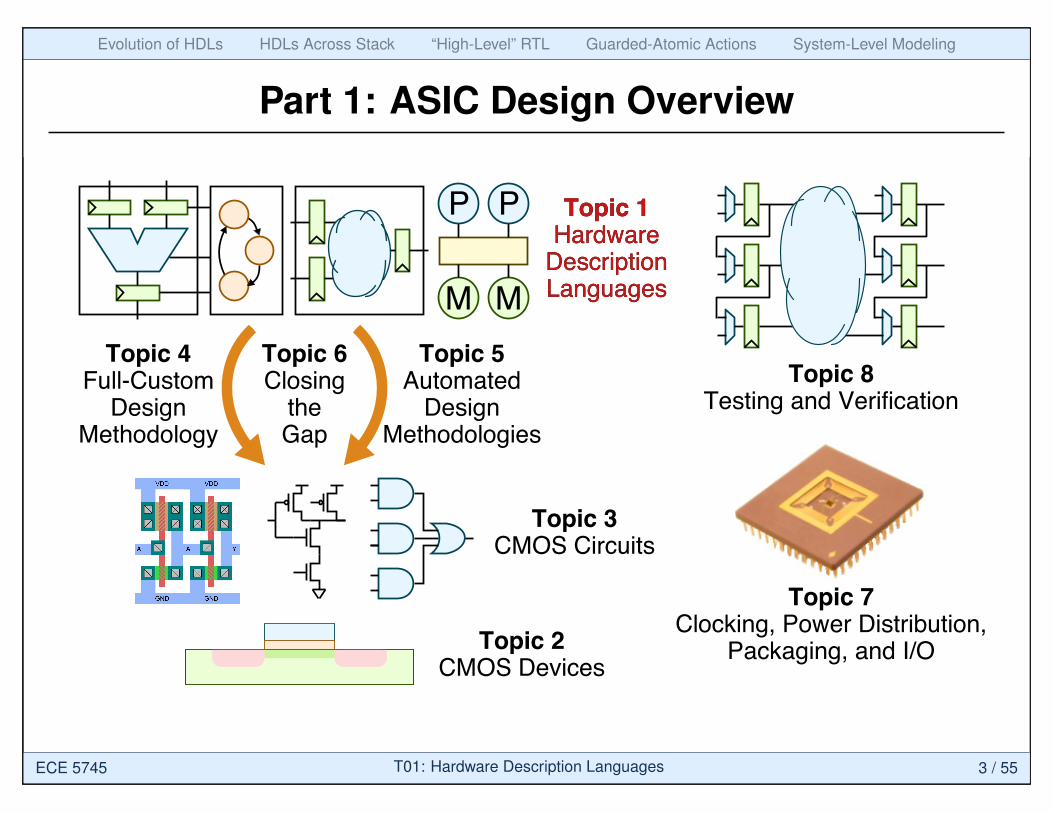
Part 1: ASIC Design Overview
P P
MM
Topic 1Hardware
DescriptionLanguages
Topic 2CMOS Devices
Topic 3CMOS Circuits
Topic 4Full-Custom
DesignMethodology
Topic 5Automated
DesignMethodologies
Topic 7Clocking, Power Distribution,
Packaging, and I/O
Topic 8Testing and Verification
Topic 6Closing
theGap
Topic 1Hardware
DescriptionLanguages
ECE 5745 T01: Hardware Description Languages 3 / 55
Evolution of HDLs HDLs Across Stack “High-Level” RTL Guarded-Atomic Actions System-Level Modeling
Agenda
Evolution of Hardware Description Languages
Hardware Description Languages Across Stack
“High-Level” RTL with SystemVerilog
Guarded-Atomic Actions with Bluespec
System-Level Modeling with SystemC
ECE 5745 T01: Hardware Description Languages 4 / 55
• Evolution of HDLs • HDLs Across Stack “High-Level” RTL Guarded-Atomic Actions System-Level Modeling
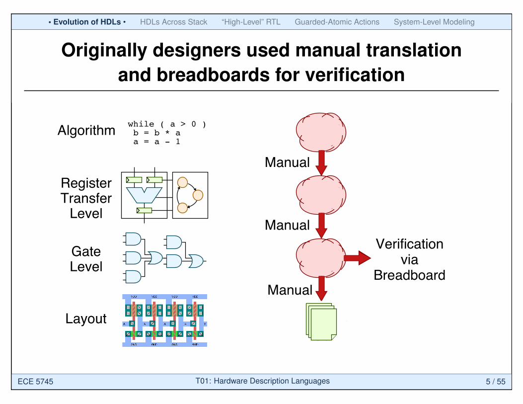
Originally designers used manual translationand breadboards for verification
Layout
RegisterTransfer
Level
Algorithmwhile ( a > 0 ) b = b * a a = a - 1
GateLevel
Manual
Manual
Manual
Verificationvia
Breadboard
ECE 5745 T01: Hardware Description Languages 5 / 55
• Evolution of HDLs • HDLs Across Stack “High-Level” RTL Guarded-Atomic Actions System-Level Modeling
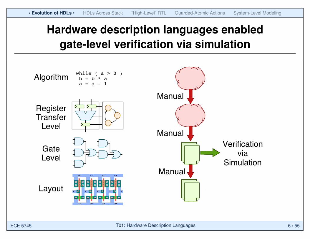
Hardware description languages enabledgate-level verification via simulation
Layout
RegisterTransfer
Level
Algorithmwhile ( a > 0 ) b = b * a a = a - 1
GateLevel
Manual
Manual
Manual
Verificationvia
Breadboard
Verificationvia
Simulation
ECE 5745 T01: Hardware Description Languages 6 / 55
• Evolution of HDLs • HDLs Across Stack “High-Level” RTL Guarded-Atomic Actions System-Level Modeling
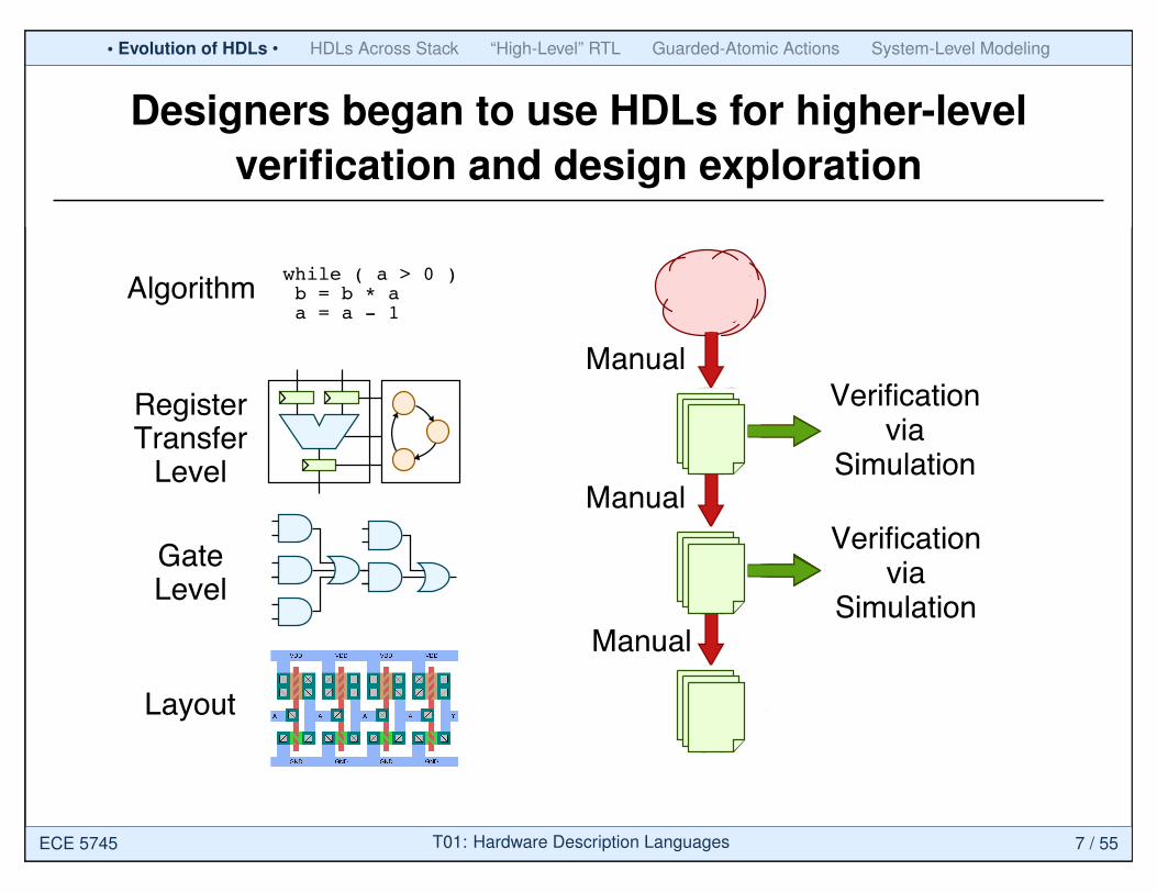
Designers began to use HDLs for higher-levelverification and design exploration
Layout
RegisterTransfer
Level
Algorithmwhile ( a > 0 ) b = b * a a = a - 1
GateLevel
Manual
Manual
Manual
Verificationvia
Breadboard
Verificationvia
Simulation
Verificationvia
Simulation
ECE 5745 T01: Hardware Description Languages 7 / 55
• Evolution of HDLs • HDLs Across Stack “High-Level” RTL Guarded-Atomic Actions System-Level Modeling
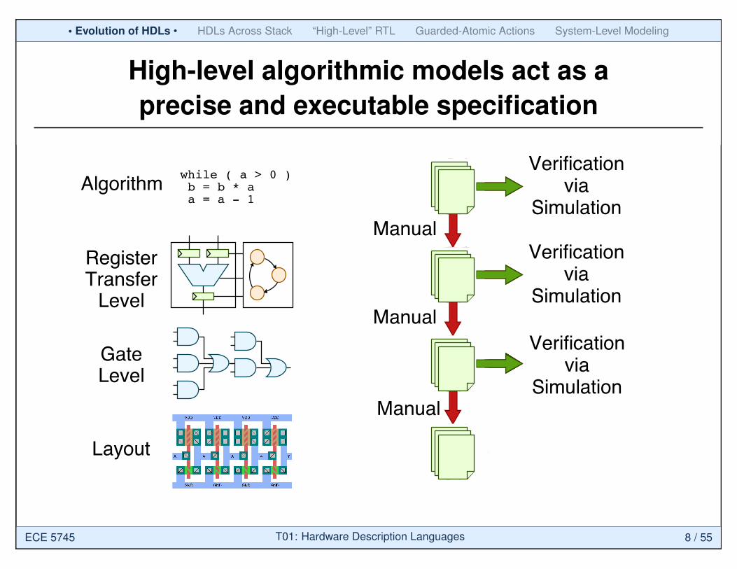
High-level algorithmic models act as aprecise and executable specification
Layout
RegisterTransfer
Level
Algorithmwhile ( a > 0 ) b = b * a a = a - 1
GateLevel
Manual
Manual
Manual
Verificationvia
Breadboard
Verificationvia
Simulation
Verificationvia
Simulation
Verificationvia
Simulation
ECE 5745 T01: Hardware Description Languages 8 / 55
• Evolution of HDLs • HDLs Across Stack “High-Level” RTL Guarded-Atomic Actions System-Level Modeling
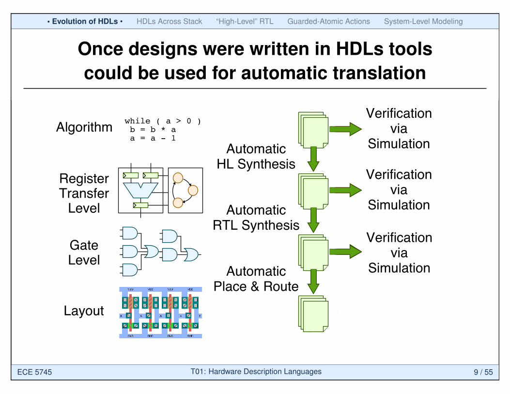
Once designs were written in HDLs toolscould be used for automatic translation
Layout
RegisterTransfer
Level
Algorithmwhile ( a > 0 ) b = b * a a = a - 1
GateLevel
Manual
Manual
Manual
Verificationvia
Breadboard
Verificationvia
Simulation
Verificationvia
Simulation
Verificationvia
Simulation
AutomaticPlace & Route
AutomaticRTL Synthesis
AutomaticHL Synthesis
ECE 5745 T01: Hardware Description Languages 9 / 55
• Evolution of HDLs • HDLs Across Stack “High-Level” RTL Guarded-Atomic Actions System-Level Modeling
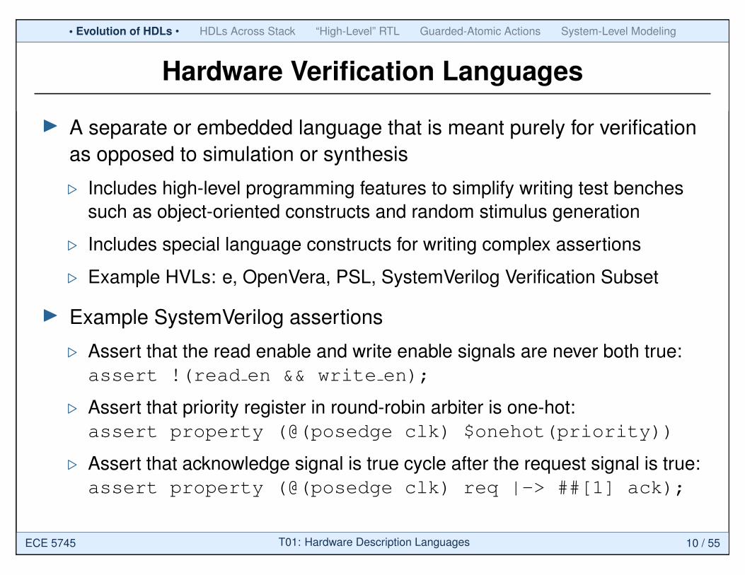
Hardware Verification Languages
I A separate or embedded language that is meant purely for verificationas opposed to simulation or synthesis
. Includes high-level programming features to simplify writing test benchessuch as object-oriented constructs and random stimulus generation
. Includes special language constructs for writing complex assertions
. Example HVLs: e, OpenVera, PSL, SystemVerilog Verification Subset
I Example SystemVerilog assertions
. Assert that the read enable and write enable signals are never both true:assert !(read en && write en);
. Assert that priority register in round-robin arbiter is one-hot:assert property (@(posedge clk) $onehot(priority))
. Assert that acknowledge signal is true cycle after the request signal is true:assert property (@(posedge clk) req |-> ##[1] ack);
ECE 5745 T01: Hardware Description Languages 10 / 55

Evolution of HDLs • HDLs Across Stack • “High-Level” RTL Guarded-Atomic Actions System-Level Modeling
Agenda
Evolution of Hardware Description Languages
Hardware Description Languages Across Stack
“High-Level” RTL with SystemVerilog
Guarded-Atomic Actions with Bluespec
System-Level Modeling with SystemC
ECE 5745 T01: Hardware Description Languages 11 / 55
Evolution of HDLs • HDLs Across Stack • “High-Level” RTL Guarded-Atomic Actions System-Level Modeling
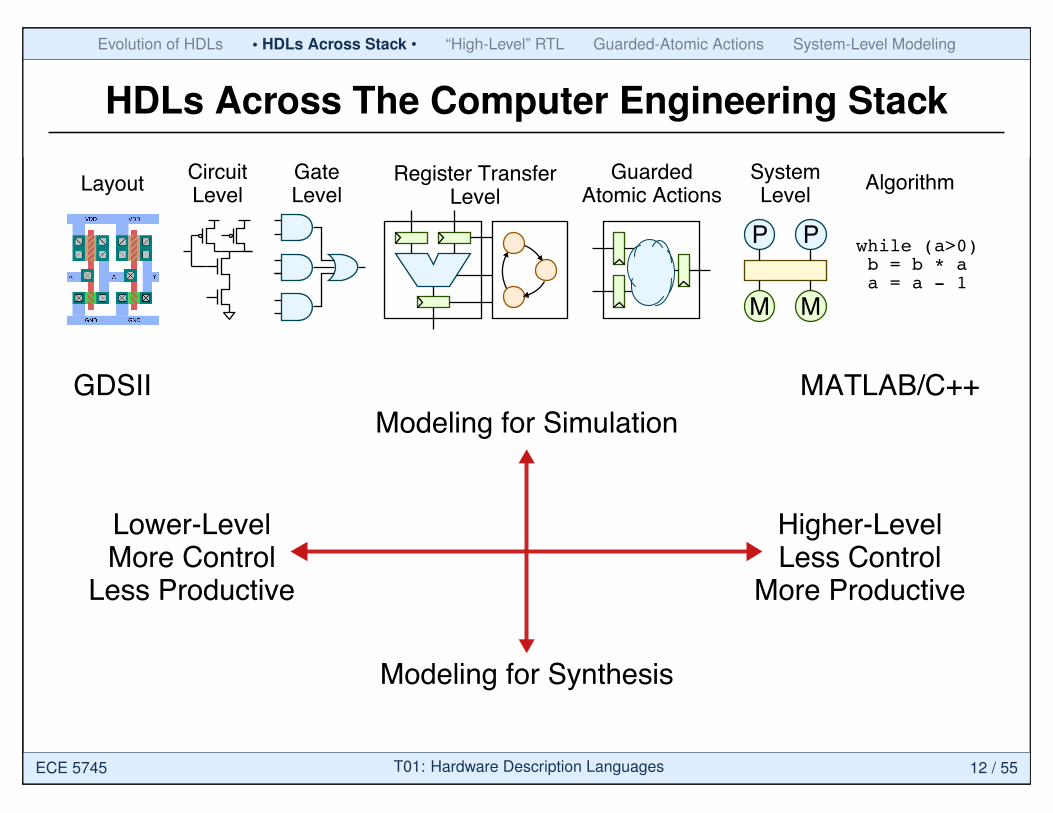
HDLs Across The Computer Engineering Stack
LayoutCircuitLevel
Register TransferLevel
GuardedAtomic Actions
SystemLevel
Algorithm
while (a>0) b = b * a a = a - 1
P P
MM
GateLevel
GDSII MATLAB/C++
Lower-LevelMore Control
Less Productive
Higher-LevelLess Control
More Productive
Modeling for Simulation
Modeling for Synthesis
ECE 5745 T01: Hardware Description Languages 12 / 55

Evolution of HDLs • HDLs Across Stack • “High-Level” RTL Guarded-Atomic Actions System-Level Modeling
Circuit-Level Modeling with Spice
LayoutCircuitLevel
Register TransferLevel
GuardedAtomic Actions
SystemLevel
Algorithm
while (a>0) b = b * a a = a - 1
P P
MM
GateLevel
* CMOS NAND gateMP1 4 1 3 3 CMOSP W=28.0U L=2.0U AS=252P AD=252PMP2 4 2 3 3 CMOSP W=28.0U L=2.0U AS=252P AD=252PMN1 4 1 5 0 CMOSN W=10.0U L=2.0U AS=90P AD=90PMN2 5 2 0 0 CMOSN W=10.0U L=2.0U AS=90P AD=90P
* Input stimulusVINA 2 0 PULSE(0 5 100ns 5ns 5ns 100n 200ns)VINB 1 0 PULSE(0 5 205ns 5ns 5ns 200n 400ns)VDD 3 0 DC 5.0
ECE 5745 T01: Hardware Description Languages 13 / 55
Evolution of HDLs • HDLs Across Stack • “High-Level” RTL Guarded-Atomic Actions System-Level Modeling
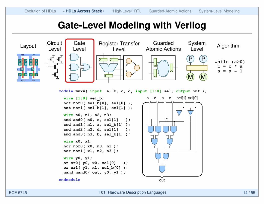
Gate-Level Modeling with Verilog
LayoutCircuitLevel
Register TransferLevel
GuardedAtomic Actions
SystemLevel
Algorithm
while (a>0) b = b * a a = a - 1
P P
MM
GateLevel
ECE 4750 Computer Architecture • Verilog Basics • 25
module mux4( input a, b, c, d, input [1:0] sel, output out );
wire [1:0] sel_b; not not0( sel_b[0], sel[0] ); not not1( sel_b[1], sel[1] );
wire n0, n1, n2, n3; and and0( n0, c, sel[1] ); and and1( n1, a, sel_b[1] ); and and2( n2, d, sel[1] ); and and3( n3, b, sel_b[1] );
wire x0, x1; nor nor0( x0, n0, n1 ); nor nor1( x1, n2, n3 );
wire y0, y1; or or0( y0, x0, sel[0] ); or or1( y1, x1, sel_b[0] ); nand nand0( out, y0, y1 );
endmodule
Gate-level Verilog uses structural
Verilog to connect primitive gates
sel[0] sel[1] c a d b
out
ECE 5745 T01: Hardware Description Languages 14 / 55
Evolution of HDLs • HDLs Across Stack • “High-Level” RTL Guarded-Atomic Actions System-Level Modeling
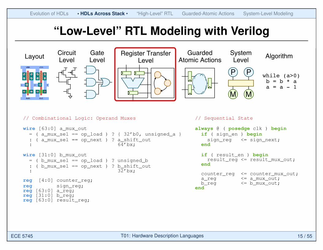
“Low-Level” RTL Modeling with Verilog
LayoutCircuitLevel
Register TransferLevel
GuardedAtomic Actions
SystemLevel
Algorithm
while (a>0) b = b * a a = a - 1
P P
MM
GateLevel
// Combinational Logic: Operand Muxes
wire [63:0] a_mux_out= ( a_mux_sel == op_load ) ? { 32’b0, unsigned_a }: ( a_mux_sel == op_next ) ? a_shift_out: 64’bx;
wire [31:0] b_mux_out= ( b_mux_sel == op_load ) ? unsigned_b: ( b_mux_sel == op_next ) ? b_shift_out: 32’bx;
reg [4:0] counter_reg;reg sign_reg;reg [63:0] a_reg;reg [31:0] b_reg;reg [63:0] result_reg;
// Sequential State
always @ ( posedge clk ) beginif ( sign_en ) beginsign_reg <= sign_next;
end
if ( result_en ) beginresult_reg <= result_mux_out;
end
counter_reg <= counter_mux_out;a_reg <= a_mux_out;b_reg <= b_mux_out;
end
ECE 5745 T01: Hardware Description Languages 15 / 55
Evolution of HDLs • HDLs Across Stack • “High-Level” RTL Guarded-Atomic Actions System-Level Modeling
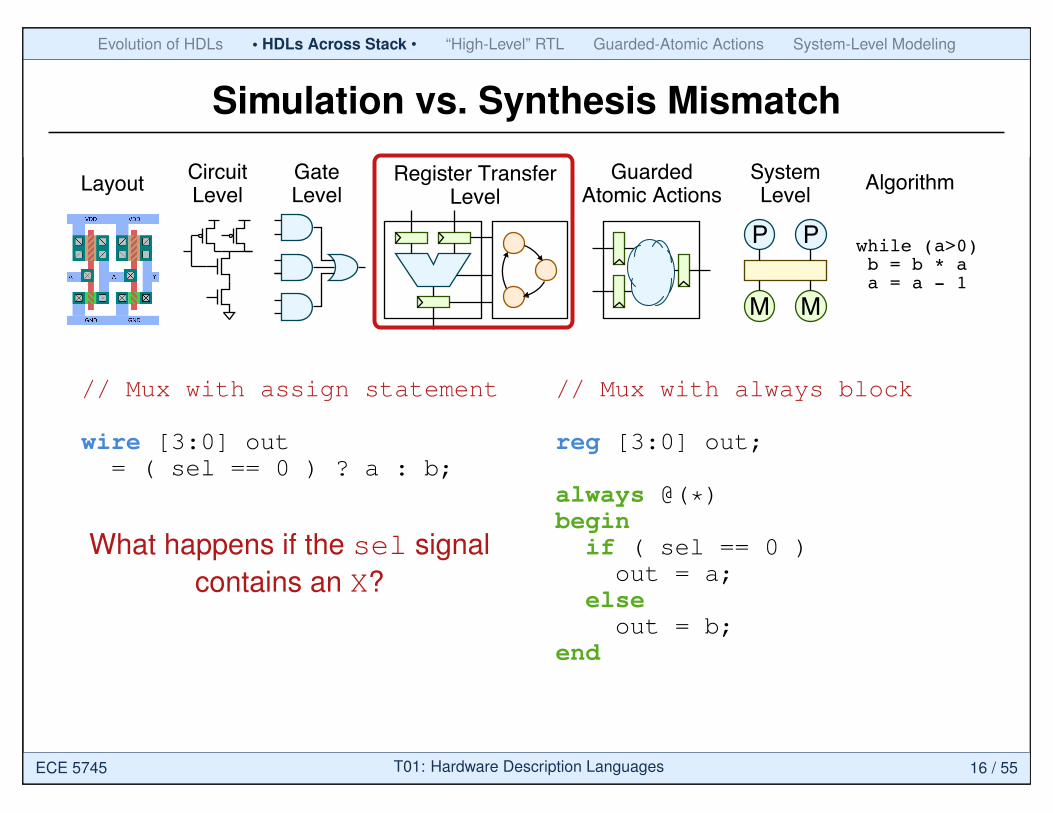
Simulation vs. Synthesis Mismatch
LayoutCircuitLevel
Register TransferLevel
GuardedAtomic Actions
SystemLevel
Algorithm
while (a>0) b = b * a a = a - 1
P P
MM
GateLevel
// Mux with assign statement
wire [3:0] out= ( sel == 0 ) ? a : b;
What happens if the sel signalcontains an X?
// Mux with always block
reg [3:0] out;
always @(*)begin
if ( sel == 0 )out = a;
elseout = b;
end
ECE 5745 T01: Hardware Description Languages 16 / 55
Evolution of HDLs • HDLs Across Stack • “High-Level” RTL Guarded-Atomic Actions System-Level Modeling
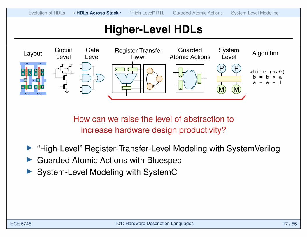
Higher-Level HDLs
LayoutCircuitLevel
Register TransferLevel
GuardedAtomic Actions
SystemLevel
Algorithm
while (a>0) b = b * a a = a - 1
P P
MM
GateLevel
How can we raise the level of abstraction toincrease hardware design productivity?
I “High-Level” Register-Transfer-Level Modeling with SystemVerilogI Guarded Atomic Actions with BluespecI System-Level Modeling with SystemC
ECE 5745 T01: Hardware Description Languages 17 / 55

Evolution of HDLs HDLs Across Stack • “High-Level” RTL • Guarded-Atomic Actions System-Level Modeling
Agenda
Evolution of Hardware Description Languages
Hardware Description Languages Across Stack
“High-Level” RTL with SystemVerilog
Guarded-Atomic Actions with Bluespec
System-Level Modeling with SystemC
ECE 5745 T01: Hardware Description Languages 18 / 55
Evolution of HDLs HDLs Across Stack • “High-Level” RTL • Guarded-Atomic Actions System-Level Modeling
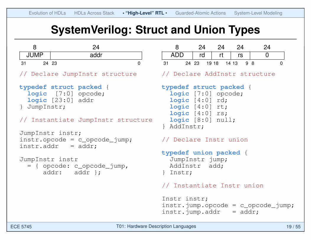
SystemVerilog: Struct and Union Types8 24
JUMP addr31 24 23 0
// Declare JumpInstr structure
typedef struct packed {logic [7:0] opcode;logic [23:0] addr
} JumpInstr;
// Instantiate JumpInstr structure
JumpInstr instr;instr.opcode = c_opcode_jump;instr.addr = addr;
JumpInstr instr= { opcode: c_opcode_jump,
addr: addr };
8 24 24 24 24ADD rd rt rs 0
31 24 23 19 18 14 13 9 8 0
// Declare AddInstr structure
typedef struct packed {logic [7:0] opcode;logic [4:0] rd;logic [4:0] rt;logic [4:0] rs;logic [8:0] null;
} AddInstr;
// Declare Instr union
typedef union packed {JumpInstr jump;AddInstr add;
} Instr;
// Instantiate Instr union
Instr instr;instr.jump.opcode = c_opcode_jump;instr.jump.addr = addr;
ECE 5745 T01: Hardware Description Languages 19 / 55
Evolution of HDLs HDLs Across Stack • “High-Level” RTL • Guarded-Atomic Actions System-Level Modeling
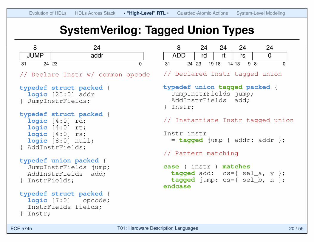
SystemVerilog: Tagged Union Types8 24
JUMP addr31 24 23 0
// Declare Instr w/ common opcode
typedef struct packed {logic [23:0] addr
} JumpInstrFields;
typedef struct packed {logic [4:0] rd;logic [4:0] rt;logic [4:0] rs;logic [8:0] null;
} AddInstrFields;
typedef union packed {JumpInstrFields jump;AddInstrFields add;
} InstrFields;
typedef struct packed {logic [7:0] opcode;InstrFields fields;
} Instr;
8 24 24 24 24ADD rd rt rs 0
31 24 23 19 18 14 13 9 8 0
// Declared Instr tagged union
typedef union tagged packed {JumpInstrFields jump;AddInstrFields add;
} Instr;
// Instantiate Instr tagged union
Instr instr= tagged jump { addr: addr };
// Pattern matching
case ( instr ) matchestagged add: cs={ sel_a, y };tagged jump: cs={ sel_b, n };
endcase
ECE 5745 T01: Hardware Description Languages 20 / 55
Evolution of HDLs HDLs Across Stack • “High-Level” RTL • Guarded-Atomic Actions System-Level Modeling
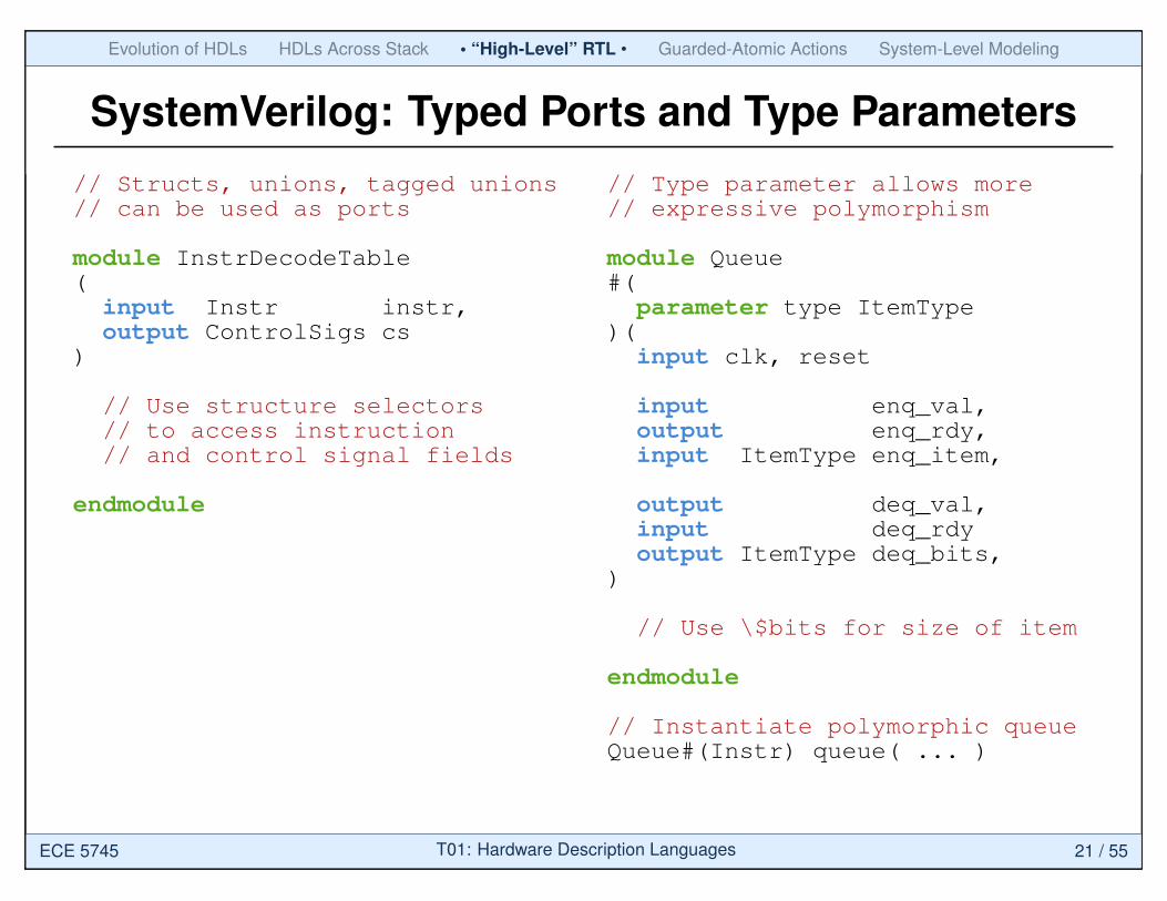
SystemVerilog: Typed Ports and Type Parameters// Structs, unions, tagged unions// can be used as ports
module InstrDecodeTable(
input Instr instr,output ControlSigs cs
)
// Use structure selectors// to access instruction// and control signal fields
endmodule
// Type parameter allows more// expressive polymorphism
module Queue#(
parameter type ItemType)(
input clk, reset
input enq_val,output enq_rdy,input ItemType enq_item,
output deq_val,input deq_rdyoutput ItemType deq_bits,
)
// Use \$bits for size of item
endmodule
// Instantiate polymorphic queueQueue#(Instr) queue( ... )
ECE 5745 T01: Hardware Description Languages 21 / 55

Evolution of HDLs HDLs Across Stack • “High-Level” RTL • Guarded-Atomic Actions System-Level Modeling
SystemVerilog: Port Bundle Interfaces// Declare valrdy interface
interface ValRdyIfc;logic val;logic rdy;logic [31:0] msg;
modport send_ifc( output val,input rdy,output msg );
modport recv_ifc( input val,output rdy,input msg );
endinterface
// Instantiate and use interface
ValRdyIfc channel;Producer producer(channel);Consumer consumer(channel);
// Using an interface
module Producer(
input clk, reset,ValRdyIfc.send_ifc send_ifc
)
// ...
always @( posedge clk )begin
send_ifc.val = ...send_ifc.msg = ...
end
endmodule
ECE 5745 T01: Hardware Description Languages 22 / 55

Evolution of HDLs HDLs Across Stack • “High-Level” RTL • Guarded-Atomic Actions System-Level Modeling
SystemVerilog: Method Interfaces// Declare valrdy method interface
interface ValRdyIfc;logic val;logic rdy;logic [31:0] msg;
// ...
function send( input logic [31:0] msg );
// ...endfunction
function is_send_done( output logic done );
// ...endfunction
endinterface
// Using an method interface
module Producer(
input clk, reset,ValRdyIfc.send_ifc send_ifc
)
// ...
logic done;
always @( posedge clk )begin
send_ifc.send( msg );send_ifc.is_send_done( done );if ( done )
...end
endmodule
ECE 5745 T01: Hardware Description Languages 23 / 55

Evolution of HDLs HDLs Across Stack • “High-Level” RTL • Guarded-Atomic Actions System-Level Modeling
SystemVerilog: Interfaces
Bus Fabric
Master
Slave Slave
Ifc Ifc
Ifc
ECE 5745 T01: Hardware Description Languages 24 / 55
Evolution of HDLs HDLs Across Stack “High-Level” RTL • Guarded-Atomic Actions • System-Level Modeling
Agenda
Evolution of Hardware Description Languages
Hardware Description Languages Across Stack
“High-Level” RTL with SystemVerilog
Guarded-Atomic Actions with Bluespec
System-Level Modeling with SystemC
ECE 5745 T01: Hardware Description Languages 25 / 55

Evolution of HDLs HDLs Across Stack “High-Level” RTL • Guarded-Atomic Actions • System-Level Modeling
Designers Usually Use Weak Interfaces
data_in push_req_n pop_req_n clk rstn
data_out
full
empty
Example: Commercially available FIFO IP block
These constraints are spread over many pages of the documentation...
Adapted from [Arvind’11]
ECE 5745 T01: Hardware Description Languages 26 / 55

Evolution of HDLs HDLs Across Stack “High-Level” RTL • Guarded-Atomic Actions • System-Level Modeling
Expressing Hardware withGuarded Atomic Actions in Bluespec
I Guarded rules. Hardware expressed as collection of rules that execute atomically
and in a well-defined serialized sequence. Allows thinking of pieces of the design in isolation. Compiler manages scheduling of rules to increase performance
I Guarded method interfaces. Formalizes composition. Compiler manages connectivity (muxing and control logic)
I Powerful type and static elaboration facilities. Significant amount of compile-time static checking. Permits parameterization of designs at all levels
ECE 5745 T01: Hardware Description Languages 27 / 55
Evolution of HDLs HDLs Across Stack “High-Level” RTL • Guarded-Atomic Actions • System-Level Modeling
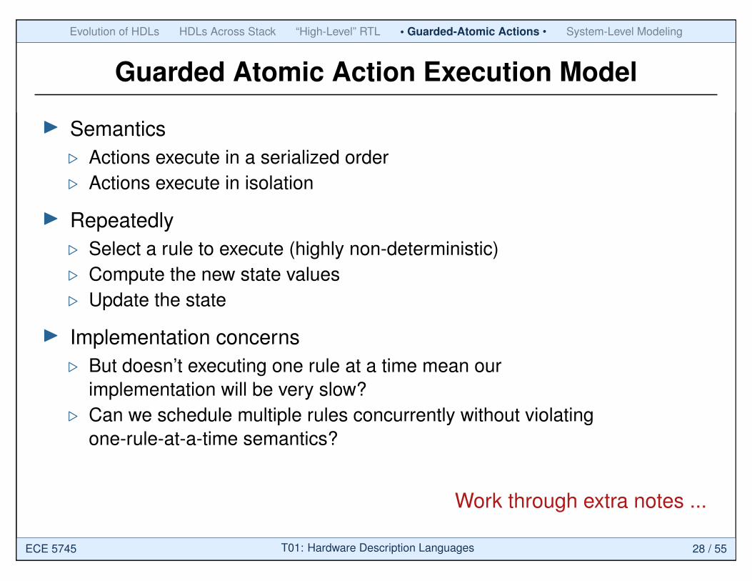
Guarded Atomic Action Execution Model
I Semantics. Actions execute in a serialized order. Actions execute in isolation
I Repeatedly. Select a rule to execute (highly non-deterministic). Compute the new state values. Update the state
I Implementation concerns. But doesn’t executing one rule at a time mean our
implementation will be very slow?. Can we schedule multiple rules concurrently without violating
one-rule-at-a-time semantics?
Work through extra notes ...
ECE 5745 T01: Hardware Description Languages 28 / 55

Evolution of HDLs HDLs Across Stack “High-Level” RTL • Guarded-Atomic Actions • System-Level Modeling
State and Rules Organized into Modules
interface
module
I All state is explicit (no inferred latches or flip-flops)I Behavior is expressed in terms of guarded rules within each module
that atomically update state internal to that moduleI Rules can manipulate state in other modules only via their guarded
method interfacesAdapted from [Arvind’11]
ECE 5745 T01: Hardware Description Languages 29 / 55
Evolution of HDLs HDLs Across Stack “High-Level” RTL • Guarded-Atomic Actions • System-Level Modeling
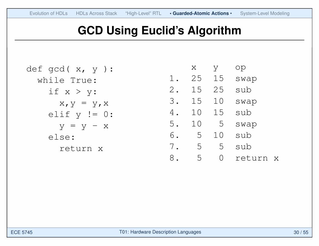
GCD Using Euclid’s Algorithm
def gcd( x, y ):while True:if x > y:x,y = y,x
elif y != 0:y = y - x
else:return x
x y op1. 25 15 swap2. 15 25 sub3. 15 10 swap4. 10 15 sub5. 10 5 swap6. 5 10 sub7. 5 5 sub8. 5 0 return x
ECE 5745 T01: Hardware Description Languages 30 / 55

Evolution of HDLs HDLs Across Stack “High-Level” RTL • Guarded-Atomic Actions • System-Level Modeling
GCD Implementation in Bluespec
module mkGCD (I_GCD);Reg#(Int#(32)) x <- mkRegU;Reg#(Int#(32)) y <- mkReg(0);
rule swap ((x > y) && (y != 0));x <= y; y <= x;
endrule
rule sub ((x <= y) && (y != 0));y <= y – x;
endrule
method Action start(Int#(32) a, Int#(32) b) if (y==0);x <= a; y <=
endmethod
method Int#(32) result() if (y==0);return x;
endmethodendmodule
ExplicitState
InternalBehavior
ExternalInterface
b;
x y
swap sub
Adapted from [Arvind’11]
ECE 5745 T01: Hardware Description Languages 31 / 55

Evolution of HDLs HDLs Across Stack “High-Level” RTL • Guarded-Atomic Actions • System-Level Modeling
GCD Alternative Implementation
module mkGCD (I_GCD);Reg#(Int#(32)) x <- mkRegU;Reg#(Int#(32)) y <- mkReg(0);
rule swapx <= y;
endrule
rule sub ((x <= y) && (y != 0));
(y != 0));
y <= y – x;endrule
method Action start(Int#(32) a, Int#(32) b) if (y==0);x <= a; y <=
endmethod
method Int#(32) result() if (y==0);return x;
endmethodendmodule
Combined
Rule
b;
y <= ;x - ysub((x > y) &&
x y op1. 25 15 swapsub2. 15 10 swapsub3. 10 5 swapsub4. 5 5 sub5. 5 0 return x
Adapted from [Arvind’11]
ECE 5745 T01: Hardware Description Languages 32 / 55
Evolution of HDLs HDLs Across Stack “High-Level” RTL • Guarded-Atomic Actions • System-Level Modeling
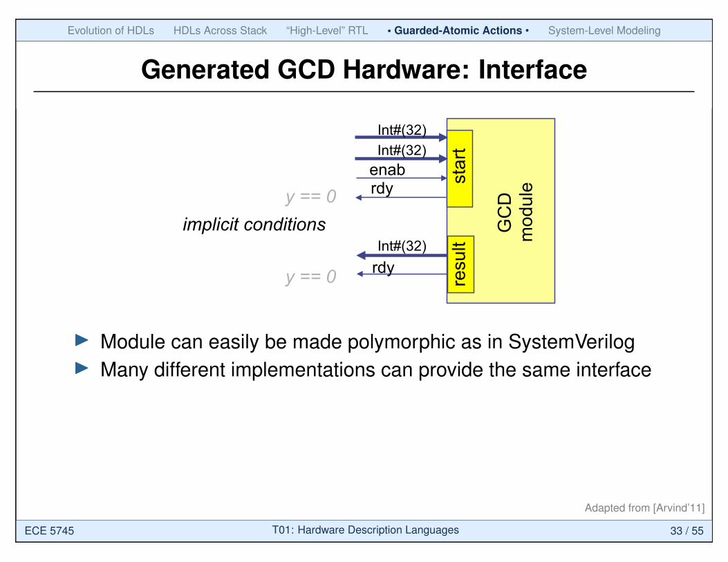
Generated GCD Hardware: Interface
rdy enab
Int#(32)
Int#(32) rdy
star
t re
sult
GC
D
mod
ule
Int#(32)
y == 0
y == 0
implicit conditions
I Module can easily be made polymorphic as in SystemVerilogI Many different implementations can provide the same interface
Adapted from [Arvind’11]
ECE 5745 T01: Hardware Description Languages 33 / 55
Evolution of HDLs HDLs Across Stack “High-Level” RTL • Guarded-Atomic Actions • System-Level Modeling
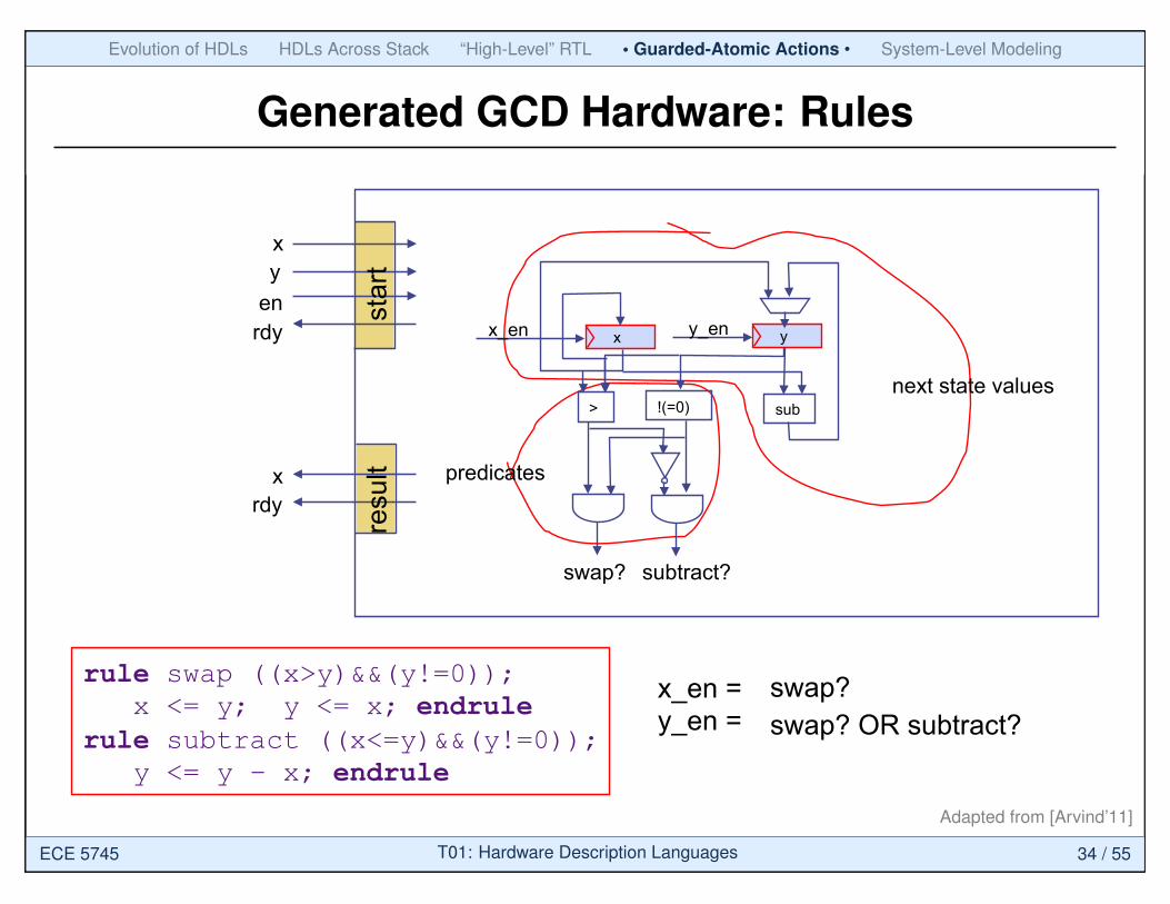
Generated GCD Hardware: Rules
next state values
predicates
x_en y_en
x_en = y_en =
x y
> !(=0)
swap? subtract?
sub
x y
en rdy
x rdy
star
t re
sult
swap? swap? OR subtract?
rule swap ((x>y)&&(y!=0)); x <= y; y <= x; endrule rule subtract ((x<=y)&&(y!=0)); y <= y – x; endrule
Adapted from [Arvind’11]
ECE 5745 T01: Hardware Description Languages 34 / 55
Evolution of HDLs HDLs Across Stack “High-Level” RTL • Guarded-Atomic Actions • System-Level Modeling
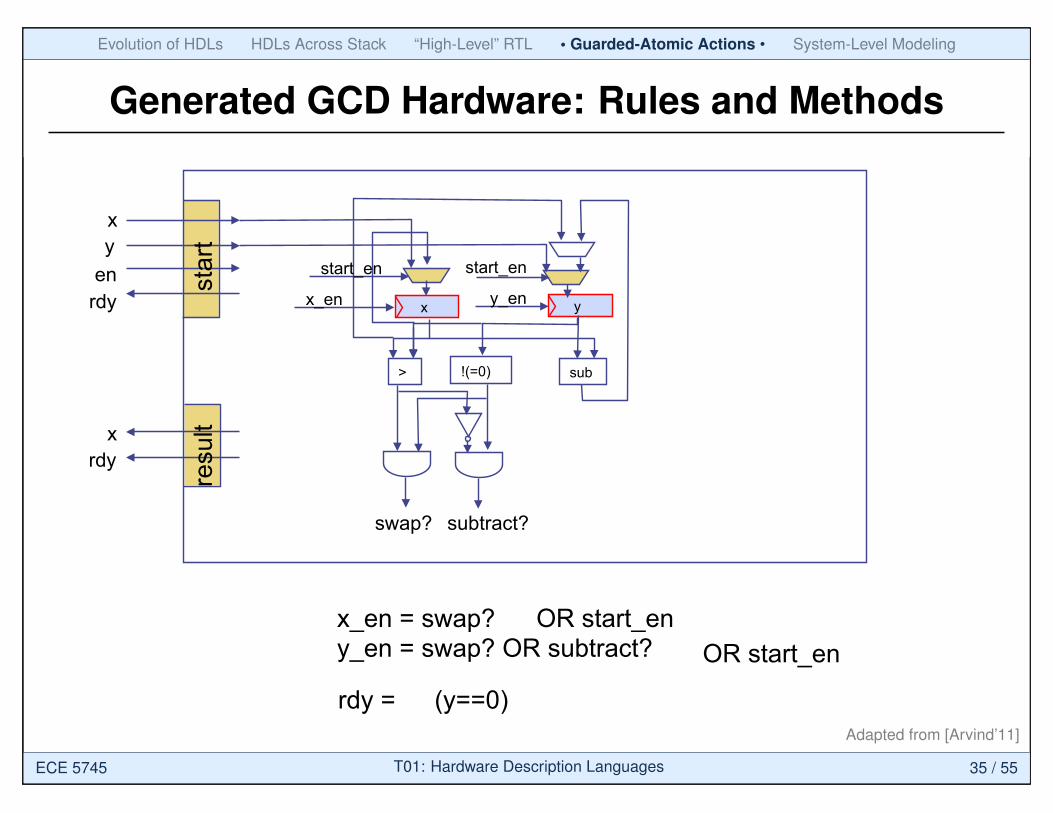
Generated GCD Hardware: Rules and Methods
x_en y_en
x_en = swap? y_en = swap? OR subtract?
x y
> !(=0)
swap? subtract?
sub
x y
en rdy
x rdy
star
t re
sult
rdy =
start_en start_en
OR start_en
(y==0)
OR start_en
Adapted from [Arvind’11]
ECE 5745 T01: Hardware Description Languages 35 / 55

Evolution of HDLs HDLs Across Stack “High-Level” RTL • Guarded-Atomic Actions • System-Level Modeling
A Systematic Approch to GAA Synthesis
A rule may be decomposed into two parts π(s) and δ(s) such that
snext = if π(s) then δ(s) else s π(s) is the condition (predicate) of the rule, a.k.a. the “CAN_FIRE” signal of the rule. π is a conjunction of explicit and implicit conditions δ(s) is the “state transformation” function, i.e., computes the next-state values from the current state values
Adapted from [Arvind’11]
ECE 5745 T01: Hardware Description Languages 36 / 55
Evolution of HDLs HDLs Across Stack “High-Level” RTL • Guarded-Atomic Actions • System-Level Modeling
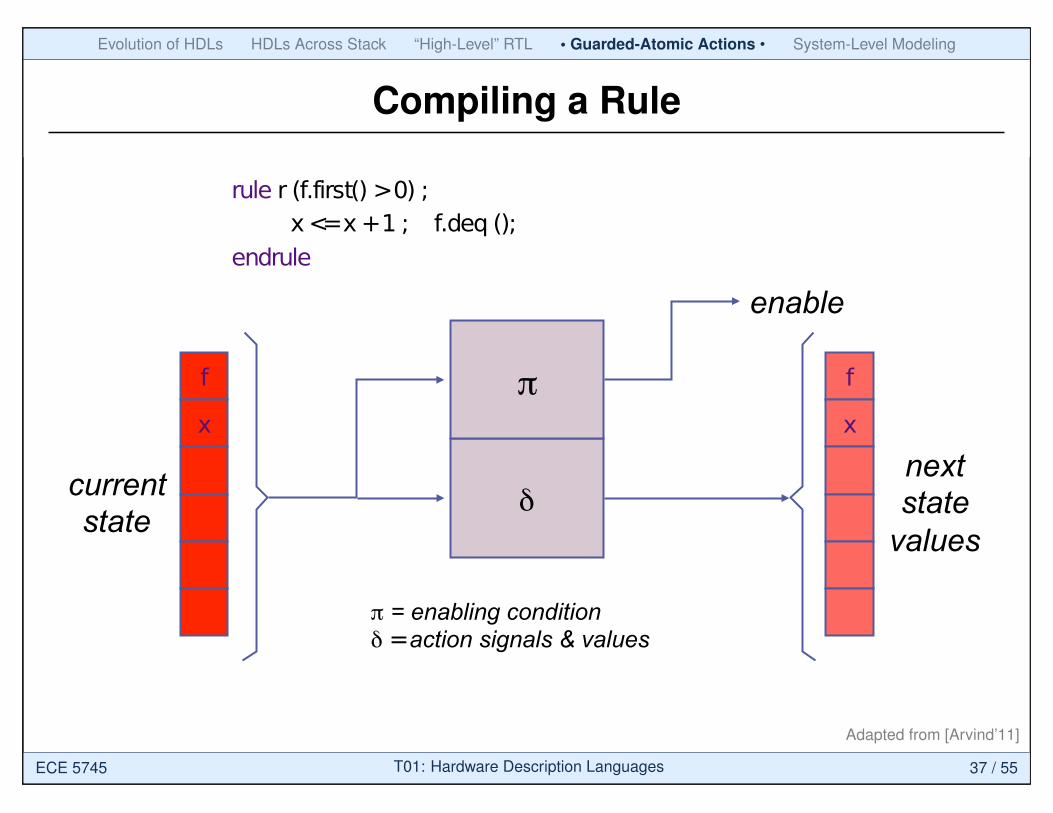
Compiling a Rule
f
x
current state
next state
values δ
π
enable
f
x
rule r (f.first() > 0) ; x <= x + 1 ; f.deq ();
endrule
π = enabling condition δ = action signals & values
Adapted from [Arvind’11]
ECE 5745 T01: Hardware Description Languages 37 / 55

Evolution of HDLs HDLs Across Stack “High-Level” RTL • Guarded-Atomic Actions • System-Level Modeling
Combining State Updates (strawman)
next state value
latch enable
R
π1
πn
δ1,R
δn,R
OR
π’s from the rules that update R
δ’s from the rules that update R
What if more than one rule is enabled?
OR
Adapted from [Arvind’11]
ECE 5745 T01: Hardware Description Languages 38 / 55

Evolution of HDLs HDLs Across Stack “High-Level” RTL • Guarded-Atomic Actions • System-Level Modeling
Combining State Updates
next state value
latch enable
R
Scheduler: Priority
Encoder
φ1
φn
π1
πn
δ1,R
δn,R
OR δ’s from the rules
that update R
Scheduler ensures that at most one φi is true
π’s from all the rules
one-rule-at-a-time scheduler is conservative
OR
Adapted from [Arvind’11]
ECE 5745 T01: Hardware Description Languages 39 / 55
Evolution of HDLs HDLs Across Stack “High-Level” RTL • Guarded-Atomic Actions • System-Level Modeling
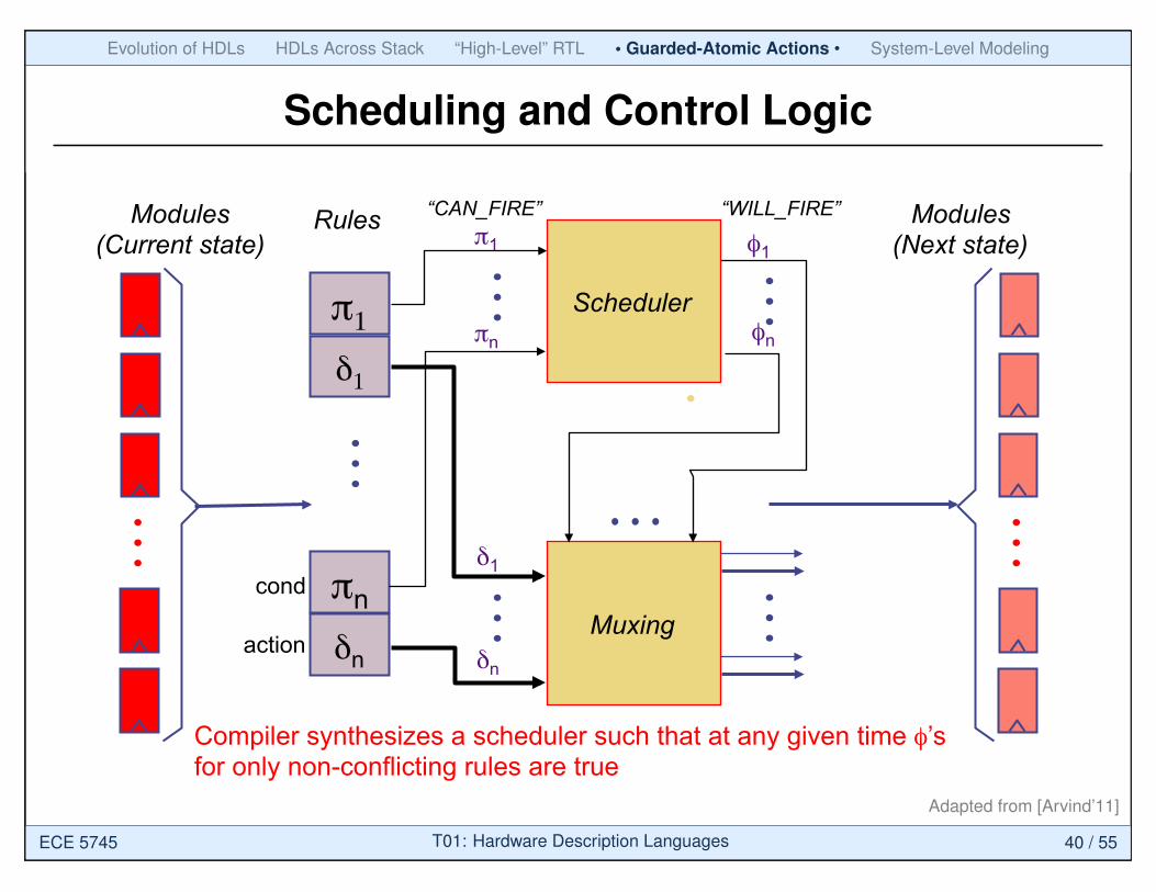
Scheduling and Control Logic
Modules (Current state)
Rules
δ1
π1
φ1
φn
π1
πn
Muxing
δ1
δn δn
πn
Modules (Next state)
cond
action
“CAN_FIRE” “WILL_FIRE”
Compiler synthesizes a scheduler such that at any given time φ’s for only non-conflicting rules are true
Scheduler
Adapted from [Arvind’11]
ECE 5745 T01: Hardware Description Languages 40 / 55
Evolution of HDLs HDLs Across Stack “High-Level” RTL Guarded-Atomic Actions • System-Level Modeling •
Agenda
Evolution of Hardware Description Languages
Hardware Description Languages Across Stack
“High-Level” RTL with SystemVerilog
Guarded-Atomic Actions with Bluespec
System-Level Modeling with SystemC
ECE 5745 T01: Hardware Description Languages 41 / 55

Evolution of HDLs HDLs Across Stack “High-Level” RTL Guarded-Atomic Actions • System-Level Modeling •
System-Level Modeling
Transaction Level Modeling: An Overview
Lukai Cai and Daniel GajskiCenter for Embedded Computer Systems
University of California, IrvineIrvine, CA 92697, USA
{lcai,gajski}@cecs.uci.edu
ABSTRACTRecently, the transaction-level modeling has been widely re-ferred to in system-level design community. However, thetransaction-level models(TLMs) are not well defined and theusage of TLMs in the existing design domains, namely mod-eling, validation, refinement, exploration, and synthesis, isnot well coordinated. This paper introduces a TLM taxon-omy and compares the benefits of TLMs’ use.
Categories and Subject DescriptorsC.0 [Computer Systems Organization]: General
General TermsDesign
KeywordsTransaction level model, modeling, validation, refinement,exploration, synthesis
1. INTRODUCTIONIn order to handle the ever increasing complexity of system-
on-chips (SoCs) and time-to-market pressures, the designabstraction has been raised to the system level in order toincrease design productivity. This higher level of abstrac-tion generated large interest in transaction-level modeling,synthesis, and verification [10][12].
In a transaction-level model (TLM), the details of com-munication among computation components are separatedfrom the details of computation components. Communica-tion is modeled by channels, while transaction requests takeplace by calling interface functions of these channel models.Unnecessary details of communication and computation arehidden in a TLM and may be added later. TLMs speed upsimulation and allow exploring and validating design alter-natives at the higher level of abstraction.
However, the definition of TLMs is not well understood.Without clear definition of TLMs, not only the predefined
Permission to make digital or hard copies of all or part of this work forpersonal or classroom use is granted without fee provided that copies arenot made or distributed for profit or commercial advantage and that copiesbear this notice and the full citation on the first page. To copy otherwise, torepublish, to post on servers or to redistribute to lists, requires prior specificpermission and/or a fee.CODES+ISSS’03, October 1–3, 2003, Newport Beach, California, USA.Copyright 2003 ACM 1-58113-742-7/03/0010 ...$5.00.
Computation
Communication
A B
C
D F
Un-timed
Approximate-timed
Cycle-timed
Un-timed
Approximate-timed
Cycle-timed
A. Specification modelB. Component-assembly modelC. Bus-arbitration modelD. Bus-functional modelE. Cycle-accurate computationmodelF. Implementation model
E
Figure 1: System modeling graph
TLMs cannot be easily reused, but also the usage of TLMsin the existing design domains, namely modeling, validation,refinement, exploration, and synthesis, cannot be systemat-ically developed. Consequently, the inherent advantages ofTLMs don’t e!ectively benefit designers. In order to elim-inate some ambiguity of TLMs, this paper attempts to ex-plicitly define several transaction-level models, each of whichis adopted for di!erent design purpose. It also explores theusage of defined TLMs under a general design flow and an-alyzes how the TLMs are used in the design domains.
This paper is organized as follows: Section 2 reviews therelated work; Section 3 defines four TLMs; Section 4 in-troduces the usage of TLMs in di!erent design domains;Finally, the conclusion is given in section 5.
2. RELATEDWORKThe concept of TLM first appears in system level lan-
guage and modeling domain. [10] defines the concept ofa channel, which enables separating communication fromcomputation. It proposes four well-defined models at di!er-ent abstraction levels in a top-down design flow. Some ofthese models can be classified as TLMs. However, the capa-bilities of TLMs are not explicitly emphasized. [12] broadlydescribes the TLM features based on the channel conceptand presents some design examples. However, the TLMsare not well defined and the usage of TLMs in the existingdesign domains is not addressed. [10] [12] also demonstratethat both SpecC [3] and SystemC [2] support transactionlevel modeling using the channel concept.
The TLMs can be used in top-down approaches such as
19
Separate computation/storagefrom communication
Adapted from [Cai’03]
ECE 5745 T01: Hardware Description Languages 42 / 55
Evolution of HDLs HDLs Across Stack “High-Level” RTL Guarded-Atomic Actions • System-Level Modeling •
Specification Model
proposed by SCE [6] that starts design from the system be-havior representing the design’s functionality, generates asystem architecture from the behavior, and gradually reachesthe implementation model by adding implementation de-tails. In comparison to the top-down approaches, meet-in-the-middle approaches [13] map the system behavior tothe predefined system architecture, rather than generatingthe architecture from the behavior. An example of meet-in-the-middle approach is VCC [5] for architecture estima-tion/exploration and N2C [1] for interface synthesis. Un-like above two approaches, bottom-up approaches assem-ble the existing computation components by inserting wrap-pers among them. Bottom-up approaches, such as proposedin [9], focus on component reuse and wrapper generation.All of above three design practices fully or partly cover thedesign from the system behavior to the detailed system im-plementation, which exhibits great potential of employingTLMs.
Some other research groups have applied TLMs in thedesign. [14] adopts TLMs to ease the development of em-bedded software. [15] defines a TLM with certain proto-col details in a platform-based design, and uses it to inte-grate components at the transaction level. [11] implementsco-simulation across-abstraction level using channels, whichimplies the usage of TLM. Each of above research addressesonly one limited aspect of TLMs.
3. TRANSACTION LEVEL MODELSIn order to simplify the design process, designers gener-
ally use a number of intermediate models. The intermedi-ate models slice the entire design into several smaller designstages, each of which has a specific design objective. Sincethe models can be simulated and estimated, the result ofeach of these design stages can be independently validated.
In order to relate di!erent models, we introduce the sys-tem modeling graph (shown in Figure 1) [8]. X-axis in thegraph represents computation and y-axis represents com-munication. On each axis, we have three degrees of timeaccuracy: un-timed, approximate-timed, and cycle-timed.Un-timed computation/communication represents the purefunctionality of the design without any implementation de-tails. Approximate-timed computation/communication con-tains system-level implementation details, such as the se-lected system architecture, the mapping relations betweenprocesses of the system specification and the processing el-ements of the system architecture. The execution time forapproximate-timed computation/communication is usuallyestimated at the system level without cycle-accurate RTL(register transfer level) /ISS (instruction set simulation) levelevaluation [5]. Cycle-timed computation/communication con-tains implementation details at both system level and theRTL/ISS level, such that cycle-accurate estimation can beobtained.
Inspired by [10] [12], we define six abstraction models inthe system modeling graph, which are indicated by circles.Among them, component-assembly model, bus-arbitrationmodel, bus-functional model, and cycle-accurate computa-tion model are TLMs, which are indicated by shaded circles.
Specification model. It describes the system function-ality and is free of any implementation details. This modelis similar to the specification model in [10] and untimedfunctional model in [12]. It can model the data transferbetween processes through variable accessing without using
v2 = v1 + b*b; v3= v1- b*b;
v1
v1 = a*a;
v2
v4 = v2 + v3;c = sequ(v4);
B1
B2
v3
B3
B4
B2B3
Figure 2: The example of specification model
v3
v3= v1- b*b;B3
v4 = v2 + v3;c = sequ(v4);
B4
PE3
v2 = v1 + b*b;B2
PE2
v1 = a*a;B1
PE1
cv2
cv12
cv11
Figure 3: The example of component-assemblymodel
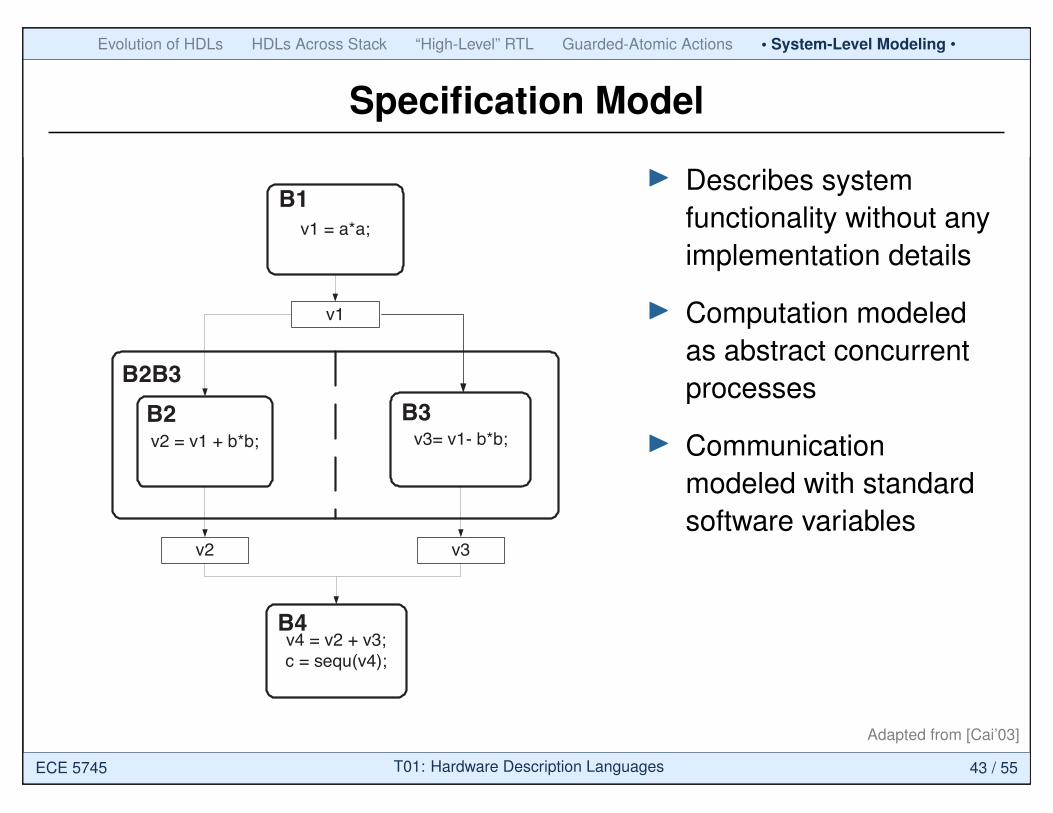
channel concept, which eases to convert C/C++ languageto SystemC/SpecC language. Specification model is an un-timed model. Figure 2 displays an example of specificationmodel. Processes B1, B2B3, and B4 execute sequentially.B2B3 is a parallel composition of B2 and B3. Variables v1,v2 and v3 are used to transfer data among processes.
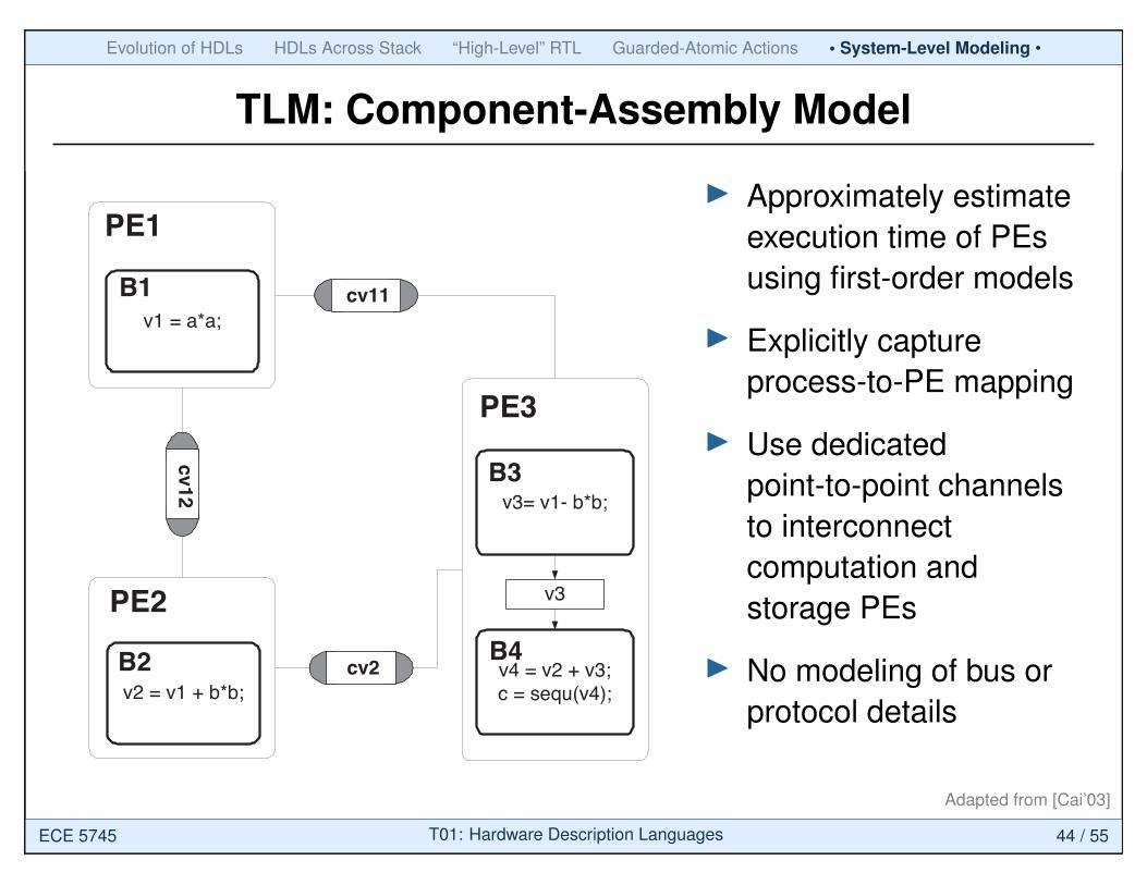
Component-assembly model. The entities at the toplevel of the model represent concurrently executing process-ing elements (PEs) and global memories, which commu-nicate through channels. A PE can be a custom hard-ware, a general-purpose processor, a DSP, or an IP. Thechannels are message passing channels, which only repre-sent data transfer or process synchronization between PEswithout any bus/protocol implementation. The communi-cation part of the model (channel) is un-timed, while com-putation part of the model (PE) is timed by approximatelyestimating the execution on specific PE. The estimated timeof computation is computed by system-level estimator suchas [5]. The estimated time is annotated into the code byinserting wait statements. Component-assembly model isthe same as architecture model defined in [10] and belongs
20
I Describes systemfunctionality without anyimplementation details
I Computation modeledas abstract concurrentprocesses
I Communicationmodeled with standardsoftware variables
Adapted from [Cai’03]
ECE 5745 T01: Hardware Description Languages 43 / 55
Evolution of HDLs HDLs Across Stack “High-Level” RTL Guarded-Atomic Actions • System-Level Modeling •
TLM: Component-Assembly Model
proposed by SCE [6] that starts design from the system be-havior representing the design’s functionality, generates asystem architecture from the behavior, and gradually reachesthe implementation model by adding implementation de-tails. In comparison to the top-down approaches, meet-in-the-middle approaches [13] map the system behavior tothe predefined system architecture, rather than generatingthe architecture from the behavior. An example of meet-in-the-middle approach is VCC [5] for architecture estima-tion/exploration and N2C [1] for interface synthesis. Un-like above two approaches, bottom-up approaches assem-ble the existing computation components by inserting wrap-pers among them. Bottom-up approaches, such as proposedin [9], focus on component reuse and wrapper generation.All of above three design practices fully or partly cover thedesign from the system behavior to the detailed system im-plementation, which exhibits great potential of employingTLMs.
Some other research groups have applied TLMs in thedesign. [14] adopts TLMs to ease the development of em-bedded software. [15] defines a TLM with certain proto-col details in a platform-based design, and uses it to inte-grate components at the transaction level. [11] implementsco-simulation across-abstraction level using channels, whichimplies the usage of TLM. Each of above research addressesonly one limited aspect of TLMs.
3. TRANSACTION LEVEL MODELSIn order to simplify the design process, designers gener-
ally use a number of intermediate models. The intermedi-ate models slice the entire design into several smaller designstages, each of which has a specific design objective. Sincethe models can be simulated and estimated, the result ofeach of these design stages can be independently validated.
In order to relate di!erent models, we introduce the sys-tem modeling graph (shown in Figure 1) [8]. X-axis in thegraph represents computation and y-axis represents com-munication. On each axis, we have three degrees of timeaccuracy: un-timed, approximate-timed, and cycle-timed.Un-timed computation/communication represents the purefunctionality of the design without any implementation de-tails. Approximate-timed computation/communication con-tains system-level implementation details, such as the se-lected system architecture, the mapping relations betweenprocesses of the system specification and the processing el-ements of the system architecture. The execution time forapproximate-timed computation/communication is usuallyestimated at the system level without cycle-accurate RTL(register transfer level) /ISS (instruction set simulation) levelevaluation [5]. Cycle-timed computation/communication con-tains implementation details at both system level and theRTL/ISS level, such that cycle-accurate estimation can beobtained.
Inspired by [10] [12], we define six abstraction models inthe system modeling graph, which are indicated by circles.Among them, component-assembly model, bus-arbitrationmodel, bus-functional model, and cycle-accurate computa-tion model are TLMs, which are indicated by shaded circles.
Specification model. It describes the system function-ality and is free of any implementation details. This modelis similar to the specification model in [10] and untimedfunctional model in [12]. It can model the data transferbetween processes through variable accessing without using
v2 = v1 + b*b; v3= v1- b*b;
v1
v1 = a*a;
v2
v4 = v2 + v3;c = sequ(v4);
B1
B2
v3
B3
B4
B2B3
Figure 2: The example of specification model
v3
v3= v1- b*b;B3
v4 = v2 + v3;c = sequ(v4);
B4
PE3
v2 = v1 + b*b;B2
PE2
v1 = a*a;B1
PE1
cv2
cv12
cv11
Figure 3: The example of component-assemblymodel
channel concept, which eases to convert C/C++ languageto SystemC/SpecC language. Specification model is an un-timed model. Figure 2 displays an example of specificationmodel. Processes B1, B2B3, and B4 execute sequentially.B2B3 is a parallel composition of B2 and B3. Variables v1,v2 and v3 are used to transfer data among processes.
Component-assembly model. The entities at the toplevel of the model represent concurrently executing process-ing elements (PEs) and global memories, which commu-nicate through channels. A PE can be a custom hard-ware, a general-purpose processor, a DSP, or an IP. Thechannels are message passing channels, which only repre-sent data transfer or process synchronization between PEswithout any bus/protocol implementation. The communi-cation part of the model (channel) is un-timed, while com-putation part of the model (PE) is timed by approximatelyestimating the execution on specific PE. The estimated timeof computation is computed by system-level estimator suchas [5]. The estimated time is annotated into the code byinserting wait statements. Component-assembly model isthe same as architecture model defined in [10] and belongs
20
I Approximately estimateexecution time of PEsusing first-order models
I Explicitly captureprocess-to-PE mapping
I Use dedicatedpoint-to-point channelsto interconnectcomputation andstorage PEs
I No modeling of bus orprotocol details
Adapted from [Cai’03]
ECE 5745 T01: Hardware Description Languages 44 / 55

Evolution of HDLs HDLs Across Stack “High-Level” RTL Guarded-Atomic Actions • System-Level Modeling •
TLM: Bus-Arbitration Model
v2 = v1 + b*b;B2
PE2
v1 = a*a;B1
PE1
v3
v3= v1- b*b;B3
v4 = v2 + v3;c = sequ(v4);
B4
PE3
cv12
cv11
cv2
PE4(Arbiter)
3
1 2
1. Master interface2. Slave interface3. Arbiter interface
Figure 4: The example of bus-arbitration model
to timed functional model defined in [12]. In compari-son to specification model, component-assembly model ex-plicitly specifies the allocated PEs in the system architec-ture and process-to-PE mapping decision. The example ofcomponent-assembly model is displayed in Figure 3. PE1,PE2 and PE3 are three allocated PEs. cv11, cv12, cv2 arethe message-passing channels.
Bus-arbitration model. In comparison to component-assembly model, channels between PEs in bus-arbitrationmodel represent buses, which are called abstract bus chan-nels. The channels still implement data transfer throughmessage passing, while bus protocols can be simplified asblocking and nonblocking I/O. No cycle-accurate and pin-accurate protocol details are specified. The abstract buschannels have estimated approximate time, which is speci-fied in the channels by one wait statement per transaction.Because several channels may be grouped to one abstractbus channel, two parameters are added to the interface func-tions of channels: logical address and bus priority. Logicaladdress distinguishes interface function calls of di!erent PEsor processes; bus priority determines the bus access sequencewhen bus conflict happens. Furthermore, a bus arbiter is in-serted into the system architecture as a new PE to arbitratethe bus conflict. Master PEs, slave PEs, and the arbiter callthe functions of di!erent interfaces of the same abstract buschannels.
Figure 4 illustrates an example of bus-arbitration modelrefined from component-assembly model in Figure 3. Thethree channels in component-assembly model are encapsu-lated into an abstract bus channel representing a system bus.In order to access the new channel, the bus masters (PE1and PE2 ), the bus slave (PE3 ), and the inserted arbiter(PE4) use di!erent channel interfaces.
Bus-functional model. It contains time/cycle accuratecommunication and approximate-timed computation. Twotypes of bus-functional model are specified: time-accuratemodel and cycle-accurate model. Time-accurate model spec-ifies the time constraint of communication, which is deter-mined by the time diagram of component’s protocol. Forexample, in Figure 5(a), the time is limited in the time rangebetween 25 and 75. Cycle-accurate model can specify thetime in terms of the bus master’s clock cycles, as displayedin Figure 5(b). The task of refining a time-accurate modelto a cycle-accurate model is called protocol refinement.
(5, 15) (5, 25)(10, 20) (5, 15)
ready
ack
address[15:0]
data[31:0]
(a)Time Diagram
(b)Cycle accurate time diagram
ready
ack
address[15:0]
data[31:0]
CLK
Lowerbound = 5 + 10 + 5 + 5 = 25Upperbound = 15 + 20 +25 + 15 =75
Figure 5: Time/cycle accurate diagram
v2 = v1 + b*b;B2
PE2
v1 = a*a;B1
PE1
v3
v3= v1- b*b;B3
v4 = v2 + v3;c = sequ(v4);
B4
PE3
PE4(Arbiter)
3
1 2
1. Master interface2. Slave interface3. Arbiter interface
readyack
address[15:0]data[31:0]
IProtocolSlav
e
readyack
address[15:0]
data[31:0]
Figure 6: The example of bus-functional model
In bus-functional model, the message-passing channels arereplaced by protocol channels. A protocol channel is time/cycle-accurate and pin-accurate. Inside a protocol channel, wiresof the bus are represented by instantiating correspondingvariables/signals. Data is transferred following the time/cycleaccurate protocol sequence. At its interface, a protocolchannel provides functions for all abstraction bus transac-tion. A protocol channel is the same as a protocol channelof [10]. We call an abstract bus channel containing a pro-tocol channel a detailed bus channel. It should be notedthat in the bus-functional model, it is not necessary to re-fine all the abstract bus channels into detailed bus chan-nels. Some abstract bus channels can be refined while othersare untouched. The refinement process from bus-arbitrationmodel to the bus-functional model is similar to the proto-col insertion introduced in [10]. Figure 6 illustrates ourbus-functional model.
Cycle-accurate computation model. It contains cycle-accurate computation and approximate-timed communica-tion. This model can be generated from the bus-arbitration
21
I Approximately estimateexecution time of PEsusing first-order models
I Explicitly capturechannel-to-bus mapping
I Still communicatethrough abstractchannels, but alsoestimate busperformance withfirst-order arbitrationmodels
Adapted from [Cai’03]
ECE 5745 T01: Hardware Description Languages 45 / 55
Evolution of HDLs HDLs Across Stack “High-Level” RTL Guarded-Atomic Actions • System-Level Modeling •
TLM: Bus-Functional Model
v2 = v1 + b*b;B2
PE2
v1 = a*a;B1
PE1
v3
v3= v1- b*b;B3
v4 = v2 + v3;c = sequ(v4);
B4
PE3
cv12
cv11
cv2
PE4(Arbiter)
3
1 2
1. Master interface2. Slave interface3. Arbiter interface
Figure 4: The example of bus-arbitration model
to timed functional model defined in [12]. In compari-son to specification model, component-assembly model ex-plicitly specifies the allocated PEs in the system architec-ture and process-to-PE mapping decision. The example ofcomponent-assembly model is displayed in Figure 3. PE1,PE2 and PE3 are three allocated PEs. cv11, cv12, cv2 arethe message-passing channels.
Bus-arbitration model. In comparison to component-assembly model, channels between PEs in bus-arbitrationmodel represent buses, which are called abstract bus chan-nels. The channels still implement data transfer throughmessage passing, while bus protocols can be simplified asblocking and nonblocking I/O. No cycle-accurate and pin-accurate protocol details are specified. The abstract buschannels have estimated approximate time, which is speci-fied in the channels by one wait statement per transaction.Because several channels may be grouped to one abstractbus channel, two parameters are added to the interface func-tions of channels: logical address and bus priority. Logicaladdress distinguishes interface function calls of di!erent PEsor processes; bus priority determines the bus access sequencewhen bus conflict happens. Furthermore, a bus arbiter is in-serted into the system architecture as a new PE to arbitratethe bus conflict. Master PEs, slave PEs, and the arbiter callthe functions of di!erent interfaces of the same abstract buschannels.
Figure 4 illustrates an example of bus-arbitration modelrefined from component-assembly model in Figure 3. Thethree channels in component-assembly model are encapsu-lated into an abstract bus channel representing a system bus.In order to access the new channel, the bus masters (PE1and PE2 ), the bus slave (PE3 ), and the inserted arbiter(PE4) use di!erent channel interfaces.
Bus-functional model. It contains time/cycle accuratecommunication and approximate-timed computation. Twotypes of bus-functional model are specified: time-accuratemodel and cycle-accurate model. Time-accurate model spec-ifies the time constraint of communication, which is deter-mined by the time diagram of component’s protocol. Forexample, in Figure 5(a), the time is limited in the time rangebetween 25 and 75. Cycle-accurate model can specify thetime in terms of the bus master’s clock cycles, as displayedin Figure 5(b). The task of refining a time-accurate modelto a cycle-accurate model is called protocol refinement.
(5, 15) (5, 25)(10, 20) (5, 15)
ready
ack
address[15:0]
data[31:0]
(a)Time Diagram
(b)Cycle accurate time diagram
ready
ack
address[15:0]
data[31:0]
CLK
Lowerbound = 5 + 10 + 5 + 5 = 25Upperbound = 15 + 20 +25 + 15 =75
Figure 5: Time/cycle accurate diagram
v2 = v1 + b*b;B2
PE2
v1 = a*a;B1
PE1
v3
v3= v1- b*b;B3
v4 = v2 + v3;c = sequ(v4);
B4
PE3
PE4(Arbiter)
3
1 2
1. Master interface2. Slave interface3. Arbiter interface
readyack
address[15:0]data[31:0]
IProtocolSlav
ereadyack
address[15:0]
data[31:0]
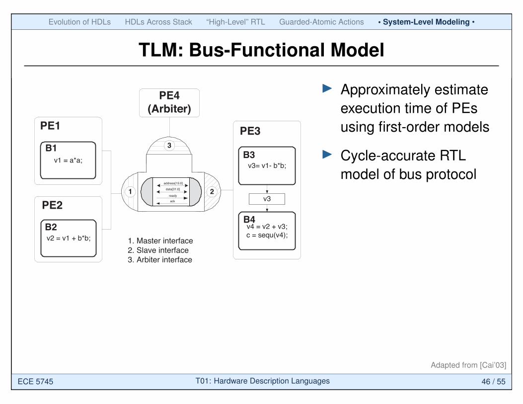
Figure 6: The example of bus-functional model
In bus-functional model, the message-passing channels arereplaced by protocol channels. A protocol channel is time/cycle-accurate and pin-accurate. Inside a protocol channel, wiresof the bus are represented by instantiating correspondingvariables/signals. Data is transferred following the time/cycleaccurate protocol sequence. At its interface, a protocolchannel provides functions for all abstraction bus transac-tion. A protocol channel is the same as a protocol channelof [10]. We call an abstract bus channel containing a pro-tocol channel a detailed bus channel. It should be notedthat in the bus-functional model, it is not necessary to re-fine all the abstract bus channels into detailed bus chan-nels. Some abstract bus channels can be refined while othersare untouched. The refinement process from bus-arbitrationmodel to the bus-functional model is similar to the proto-col insertion introduced in [10]. Figure 6 illustrates ourbus-functional model.
Cycle-accurate computation model. It contains cycle-accurate computation and approximate-timed communica-tion. This model can be generated from the bus-arbitration
21
I Approximately estimateexecution time of PEsusing first-order models
I Cycle-accurate RTLmodel of bus protocol
Adapted from [Cai’03]
ECE 5745 T01: Hardware Description Languages 46 / 55

Evolution of HDLs HDLs Across Stack “High-Level” RTL Guarded-Atomic Actions • System-Level Modeling •
TLM: Cycle-Accurate Computation Model
Models Communication Computation Communication PE interfacetime time scheme
Specification model no no variable/channel (no PE)Component-assembly no approximate message- abstractmodel passing channelBus-transaction model approximate approximate abstract bus channel abstractBus-functional time/cycle approximate detailed abstractmodel accurate bus channelCycle-accurate approximate cycle-accurate abstract bus channel pin-accuratecomputation modelImplementation model cycle-accurate cycle-accurate wire pin-accurate
Table 1: Characteristics of di!erent abstraction models
v2 = v1 + b*b;B2
PE2
v1 = a*a;B1
PE1 PE3
cv12
cv11
cv2
PE4(Arbiter)
3
1 2
1. Master interface2. Slave interface3. Arbiter interface4. Wrapper
S0
S1
S2
S3
S4
4
Figure 7: The example of cycle-accurate computa-tion model
model. In this model, computation components (PEs) arepin accurate and execute cycle-accurately. The custom hard-ware components are modeled at register-transfer level, andgeneral-purpose processors and DSPs are modeled in termsof cycle-accurate instruction set architecture. To enablecommunication between cycle-accurate PEs and abstractlevel interfaces of abstract bus channels, wrappers whichconvert data transfer from higher level of abstraction tolower level abstraction are inserted to bridge the PEs andthe bus interfaces. Similar to the bus-functional model, itis not necessary to refine all the PEs to the cycle-accuratelevel. Some PEs can be refined while others are untouched.Figure 7 illustrates a cycle-accurate computation model, inwhich only PE3 is refined to a time-accurate and pin-accuratemodel.
Implementation model. It has both cycle-accuratecommunication and cycle-accurate computation. The com-ponents are defined in terms of their register-transfer orinstruction-set architecture. The implementation model canbe obtained from the bus-functional model or the cycle-accurate computation model. The implementation model isthe same as the implementation model in [10] and register-transfer level model in [12]. Figure 8 displays an exampleof the implementation model. PE1 and PE2 are micro-processors while PE3 and PE4 are custom-hardwares.
Table 1 summaries the characteristics of di!erent abstrac-tion models. Although models indicated by ! in Figure 1can also be specified, they will not be discussed in this paperbecause they are not commonly used.
PE2PE1
PE3PE4
S0
S1
S2
S3
S4
MOV r1, 10MUL r1, r1, r1
....
...MLA r1, r2, r2, r1
....
S0
S1
S2
S3
MCNTRMADDRMDATA
interrupt
interrupt
interrupt
req req
Figure 8: The example of implementation model
4. SYSTEM DESIGNWITH TLMS
4.1 Design FlowThe gray solid arrow in Figure 1 represents a well-accepted
design flow. It goes through models A, C, and F, which rep-resents system functionality, abstract system architecture,and cycle-accurate system implementation respectively. Amongthem, bus-arbitration model divides the system flow into twostages: system design stage and component design stage.System design stage selects/generates system architectureand maps the system behavior to that architecture. Compo-nent design stage refines/systhezises computation and com-munication components to the cycle accurate level. In gen-eral, di!erent design flows include di!erent models. For ex-ample, [10] goes through models A, B, D and F, [9] goesthrough models A, C, E and F, while [12] goes throughmodels A, B, C, D and F.
4.2 Design Domain DefinitionIn Figure 1, we use arrows to represent a set of tasks that
generate one abstraction model from the previous one. Fig-ure 9 shows a general design flow with five design domainsfor generating model B from model A.
1. Modeling domain. It deals with languages and stylesof writing models. In other words, it deals with seman-
22
I Cycle-accurate RTLmodel of (some) PEs
I Adapters interfacelower-level RTLinterface to higher-levelbus-arbitration model
I Still communicatethrough abstractchannels, but alsoestimate busperformance withfirst-order arbitrationmodels
Adapted from [Cai’03]
ECE 5745 T01: Hardware Description Languages 47 / 55
Evolution of HDLs HDLs Across Stack “High-Level” RTL Guarded-Atomic Actions • System-Level Modeling •
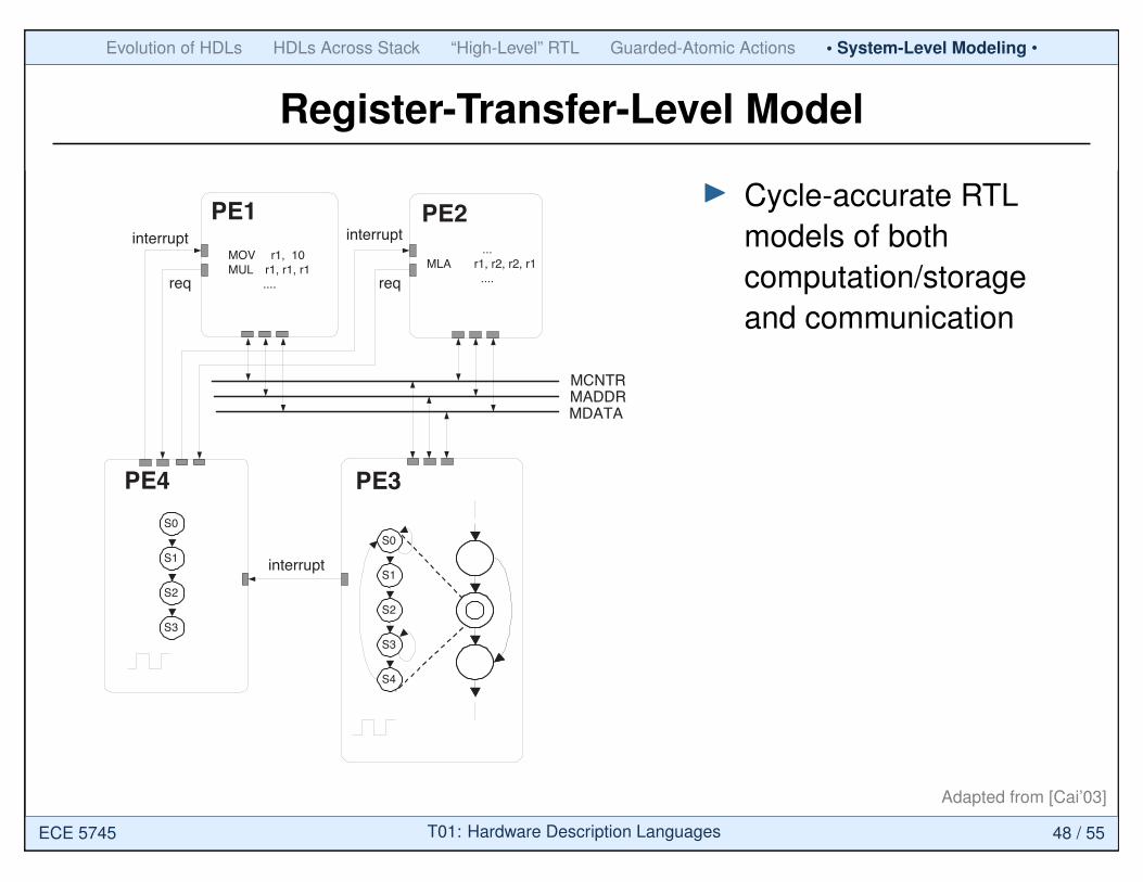
Register-Transfer-Level Model
Models Communication Computation Communication PE interfacetime time scheme
Specification model no no variable/channel (no PE)Component-assembly no approximate message- abstractmodel passing channelBus-transaction model approximate approximate abstract bus channel abstractBus-functional time/cycle approximate detailed abstractmodel accurate bus channelCycle-accurate approximate cycle-accurate abstract bus channel pin-accuratecomputation modelImplementation model cycle-accurate cycle-accurate wire pin-accurate
Table 1: Characteristics of di!erent abstraction models
v2 = v1 + b*b;B2
PE2
v1 = a*a;B1
PE1 PE3
cv12
cv11
cv2
PE4(Arbiter)
3
1 2
1. Master interface2. Slave interface3. Arbiter interface4. Wrapper
S0
S1
S2
S3
S4
4
Figure 7: The example of cycle-accurate computa-tion model
model. In this model, computation components (PEs) arepin accurate and execute cycle-accurately. The custom hard-ware components are modeled at register-transfer level, andgeneral-purpose processors and DSPs are modeled in termsof cycle-accurate instruction set architecture. To enablecommunication between cycle-accurate PEs and abstractlevel interfaces of abstract bus channels, wrappers whichconvert data transfer from higher level of abstraction tolower level abstraction are inserted to bridge the PEs andthe bus interfaces. Similar to the bus-functional model, itis not necessary to refine all the PEs to the cycle-accuratelevel. Some PEs can be refined while others are untouched.Figure 7 illustrates a cycle-accurate computation model, inwhich only PE3 is refined to a time-accurate and pin-accuratemodel.
Implementation model. It has both cycle-accuratecommunication and cycle-accurate computation. The com-ponents are defined in terms of their register-transfer orinstruction-set architecture. The implementation model canbe obtained from the bus-functional model or the cycle-accurate computation model. The implementation model isthe same as the implementation model in [10] and register-transfer level model in [12]. Figure 8 displays an exampleof the implementation model. PE1 and PE2 are micro-processors while PE3 and PE4 are custom-hardwares.
Table 1 summaries the characteristics of di!erent abstrac-tion models. Although models indicated by ! in Figure 1can also be specified, they will not be discussed in this paperbecause they are not commonly used.
PE2PE1
PE3PE4
S0
S1
S2
S3
S4
MOV r1, 10MUL r1, r1, r1
....
...MLA r1, r2, r2, r1
....
S0
S1
S2
S3
MCNTRMADDRMDATA
interrupt
interrupt
interrupt
req req
Figure 8: The example of implementation model
4. SYSTEM DESIGNWITH TLMS
4.1 Design FlowThe gray solid arrow in Figure 1 represents a well-accepted
design flow. It goes through models A, C, and F, which rep-resents system functionality, abstract system architecture,and cycle-accurate system implementation respectively. Amongthem, bus-arbitration model divides the system flow into twostages: system design stage and component design stage.System design stage selects/generates system architectureand maps the system behavior to that architecture. Compo-nent design stage refines/systhezises computation and com-munication components to the cycle accurate level. In gen-eral, di!erent design flows include di!erent models. For ex-ample, [10] goes through models A, B, D and F, [9] goesthrough models A, C, E and F, while [12] goes throughmodels A, B, C, D and F.
4.2 Design Domain DefinitionIn Figure 1, we use arrows to represent a set of tasks that
generate one abstraction model from the previous one. Fig-ure 9 shows a general design flow with five design domainsfor generating model B from model A.
1. Modeling domain. It deals with languages and stylesof writing models. In other words, it deals with seman-
22
I Cycle-accurate RTLmodels of bothcomputation/storageand communication
Adapted from [Cai’03]
ECE 5745 T01: Hardware Description Languages 48 / 55
Evolution of HDLs HDLs Across Stack “High-Level” RTL Guarded-Atomic Actions • System-Level Modeling •
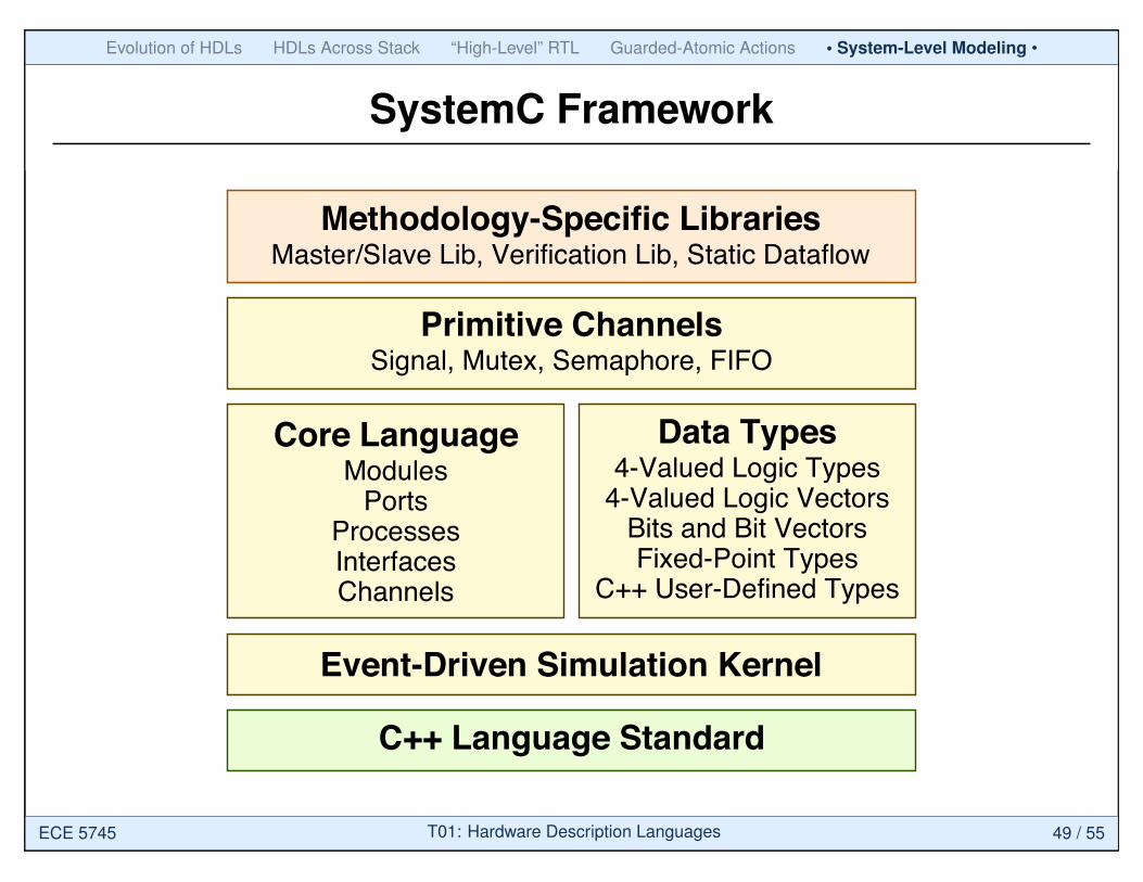
SystemC Framework
Methodology-Specific LibrariesMaster/Slave Lib, Verification Lib, Static Dataflow
Core LanguageModules
PortsProcessesInterfacesChannels
Data Types4-Valued Logic Types
4-Valued Logic VectorsBits and Bit VectorsFixed-Point Types
C++ User-Defined Types
Event-Driven Simulation Kernel
C++ Language Standard
Primitive ChannelsSignal, Mutex, Semaphore, FIFO
ECE 5745 T01: Hardware Description Languages 49 / 55
Evolution of HDLs HDLs Across Stack “High-Level” RTL Guarded-Atomic Actions • System-Level Modeling •
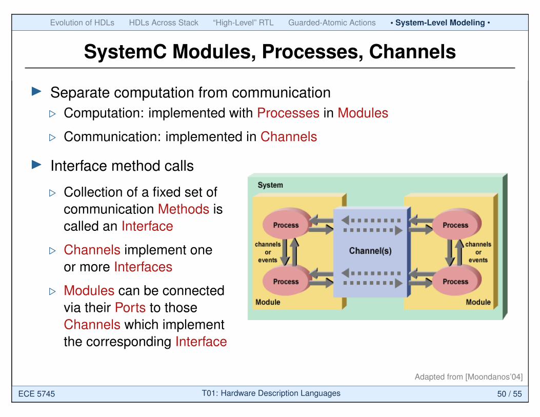
SystemC Modules, Processes, Channels
I Separate computation from communication. Computation: implemented with Processes in Modules
. Communication: implemented in Channels
I Interface method calls
. Collection of a fixed set ofcommunication Methods iscalled an Interface
. Channels implement oneor more Interfaces
. Modules can be connectedvia their Ports to thoseChannels which implementthe corresponding Interface
Adapted from [Moondanos’04]
ECE 5745 T01: Hardware Description Languages 50 / 55
Evolution of HDLs HDLs Across Stack “High-Level” RTL Guarded-Atomic Actions • System-Level Modeling •
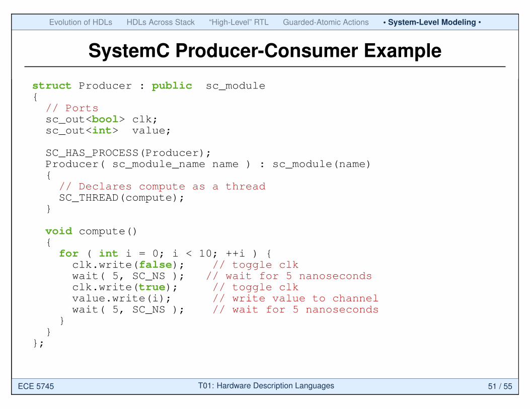
SystemC Producer-Consumer Example
struct Producer : public sc_module{
// Portssc_out<bool> clk;sc_out<int> value;
SC_HAS_PROCESS(Producer);Producer( sc_module_name name ) : sc_module(name){
// Declares compute as a threadSC_THREAD(compute);
}
void compute(){
for ( int i = 0; i < 10; ++i ) {clk.write(false); // toggle clkwait( 5, SC_NS ); // wait for 5 nanosecondsclk.write(true); // toggle clkvalue.write(i); // write value to channelwait( 5, SC_NS ); // wait for 5 nanoseconds
}}
};
ECE 5745 T01: Hardware Description Languages 51 / 55
Evolution of HDLs HDLs Across Stack “High-Level” RTL Guarded-Atomic Actions • System-Level Modeling •
SystemC Producer-Consumer Example
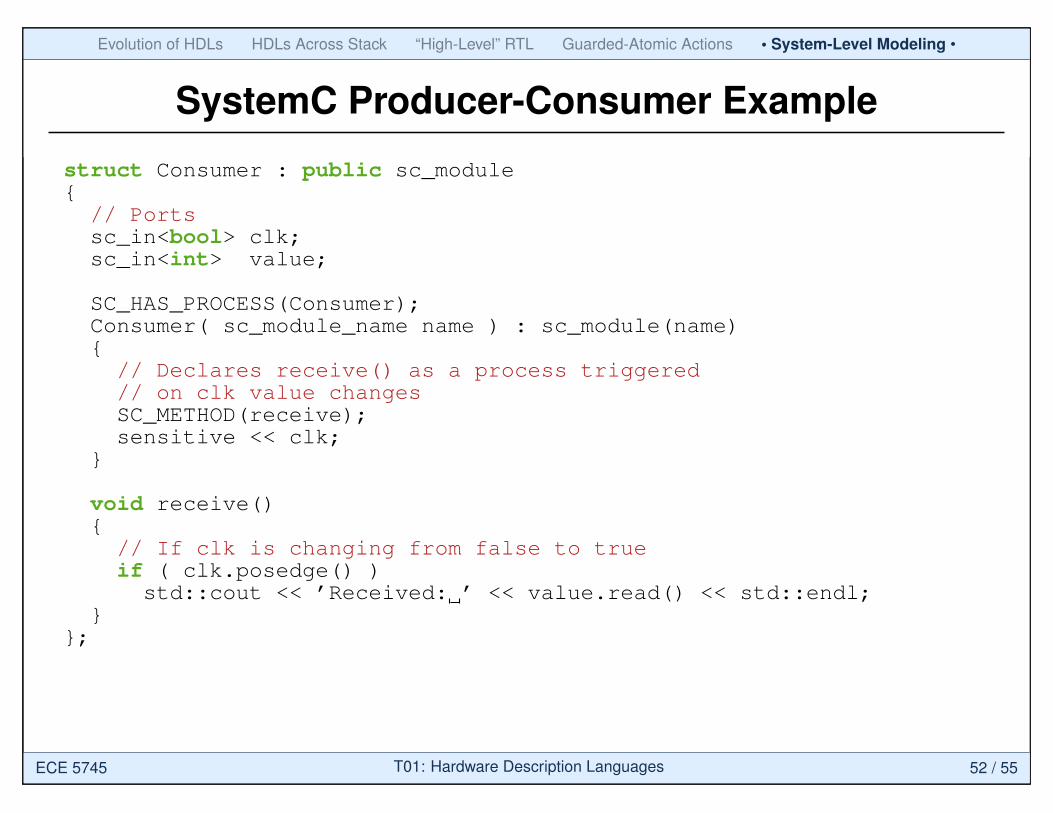
struct Consumer : public sc_module{
// Portssc_in<bool> clk;sc_in<int> value;
SC_HAS_PROCESS(Consumer);Consumer( sc_module_name name ) : sc_module(name){
// Declares receive() as a process triggered// on clk value changesSC_METHOD(receive);sensitive << clk;
}
void receive(){
// If clk is changing from false to trueif ( clk.posedge() )
std::cout << ’Received: ’ << value.read() << std::endl;}
};
ECE 5745 T01: Hardware Description Languages 52 / 55

Evolution of HDLs HDLs Across Stack “High-Level” RTL Guarded-Atomic Actions • System-Level Modeling •
SystemC System
Adapted from [Moondanos’04]
ECE 5745 T01: Hardware Description Languages 53 / 55
Evolution of HDLs HDLs Across Stack “High-Level” RTL Guarded-Atomic Actions System-Level Modeling
Take-Away Points
LayoutCircuitLevel
Register TransferLevel
GuardedAtomic Actions
SystemLevel
Algorithm
while (a>0) b = b * a a = a - 1
P P
MM
GateLevel
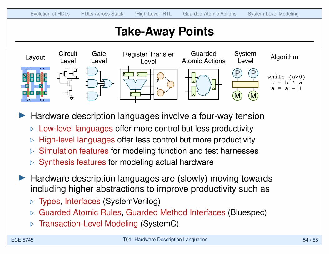
I Hardware description languages involve a four-way tension. Low-level languages offer more control but less productivity. High-level languages offer less control but more productivity. Simulation features for modeling function and test harnesses. Synthesis features for modeling actual hardware
I Hardware description languages are (slowly) moving towardsincluding higher abstractions to improve productivity such as. Types, Interfaces (SystemVerilog). Guarded Atomic Rules, Guarded Method Interfaces (Bluespec). Transaction-Level Modeling (SystemC)
ECE 5745 T01: Hardware Description Languages 54 / 55

Evolution of HDLs HDLs Across Stack “High-Level” RTL Guarded-Atomic Actions System-Level Modeling
Acknowledgments
I [Arvind’11] Arvind, “Introduction to Bluespec,” MIT 6.375 ComplexDigital Systems, Lecture, 2011.
I [Cai’03] L. Cai and D. Gajski, “Transaction Level Modeling: AnOverview,” Int’l Conf. on Hardware/Software Codesign and SystemSynthesis, Oct. 2003.
I [Moondanos’04] J. Moondanos, “SystemC Tutorial,” UC Berkeley EE249 Embedded System Design, Guest Lecture, 2004.
ECE 5745 T01: Hardware Description Languages 55 / 55