Christmas Valley Airport Airport Layout Plan Report · CHRISTMAS VALLEY Christmas Valley Airport...
100
CHRISTMAS VALLEY Christmas Valley Airport PARKS AND RECREATION DISTRICT Airport Layout Plan Report June 2003 i Century West Engineering Aron Faegre & Associates Gazeley & Associates Christmas Valley Airport Airport Layout Plan Report Final Report June 2003 Prepared for CHRISTMAS VALLEY PARKS AND RECREATION DISTRICT Prepared by Century West Engineering 6650 SW Redwood Lane, Suite 300 Portland, Oregon 97224 Tel. 503.419.2130 Fax 503.639.2710 www.centurywest.com In Association With Aron Faegre & Associates Portland, Oregon Gazeley & Associates Corvallis, Oregon
Transcript of Christmas Valley Airport Airport Layout Plan Report · CHRISTMAS VALLEY Christmas Valley Airport...

CHRISTMAS VALLEY Christmas Valley Airport PARKS AND RECREATION DISTRICT Airport Layout Plan Report
June 2003 i Century West Engineering Aron Faegre & Associates Gazeley & Associates
Christmas Valley Airport
Airport Layout Plan Report Final Report June 2003
Prepared for CHRISTMAS VALLEY PARKS AND RECREATION DISTRICT Prepared by
Century West Engineering
6650 SW Redwood Lane, Suite 300 Portland, Oregon 97224 Tel. 503.419.2130 Fax 503.639.2710 www.centurywest.com
In Association With Aron Faegre & Associates Portland, Oregon
Gazeley & Associates Corvallis, Oregon

CHRISTMAS VALLEY Christmas Valley Airport PARKS AND RECREATION DISTRICT Airport Layout Plan Report
June 2003 i Century West Engineering Aron Faegre & Associates Gazeley & Associates
TABLE OF CONTENTS
CHAPTER ONE INTRODUCTION AND SUMMARY ........................................................1-1 PUBLIC INVOLVEMENT .............................................................................................................1-2 AIRPORT LAYOUT PLAN REPORT CONCLUSIONS ..............................................................1-3 AIRPORT LAYOUT PLAN RECOMMENDATIONS..................................................................1-4
CHAPTER TWO INVENTORY AND FORECASTS ...........................................................2-1 INTRODUCTION ...........................................................................................................................2-1 AIRPORT LOCALE........................................................................................................................2-1 CLIMATE........................................................................................................................................2-2 GEOLOGY ......................................................................................................................................2-2 SOCIOECONOMIC CONDITIONS...............................................................................................2-3
Population ....................................................................................................................................2-3 Economy.......................................................................................................................................2-4 Airport History .............................................................................................................................2-4 Airport Environment ....................................................................................................................2-5
AIRFIELD FACILITIES.................................................................................................................2-5 Runways and Taxiways ................................................................................................................2-8 Aircraft Apron ..............................................................................................................................2-9 Agricultural Aircraft Facilities ....................................................................................................2-9 Airfield Pavement Condition........................................................................................................2-9
LANDSIDE FACILITIES .............................................................................................................2-10 Hangars and Airport Buildings..................................................................................................2-10 Airport Lighting .........................................................................................................................2-11 Airspace and Navigational Aids.................................................................................................2-11
AIRPORT SUPPORT FACILITIES/SERVICES..........................................................................2-13 Aircraft Fuel...............................................................................................................................2-13 Surface Access and Vehicle Parking..........................................................................................2-13 Fencing.......................................................................................................................................2-14 Utilities.......................................................................................................................................2-14 Land Use Planning and Zoning .................................................................................................2-14 Airport Service Area ..................................................................................................................2-15
AVIATION ACTIVITY AND FORECASTS...............................................................................2-16 Historical Aviation Activity........................................................................................................2-16 Forecasts of Activity...................................................................................................................2-18 Based Aircraft ............................................................................................................................2-19 Aircraft Operations ....................................................................................................................2-20 Airfield Capacity ........................................................................................................................2-20
CHAPTER THREE AIRPORT FACILITY REQUIREMENTS..........................................3-1 INTRODUCTION ...........................................................................................................................3-1 AIRPORT PLANNING OVERVIEW.............................................................................................3-2 LAND UTILIZATION....................................................................................................................3-2 AIRSPACE ......................................................................................................................................3-3 INSTRUMENT APPROACH CAPABILITIES..............................................................................3-4 AIRPORT DESIGN STANDARDS................................................................................................3-5
Runway Safety Area (RSA).........................................................................................................3-10

CHRISTMAS VALLEY Christmas Valley Airport PARKS AND RECREATION DISTRICT Airport Layout Plan Report
June 2003 ii Century West Engineering Aron Faegre & Associates Gazeley & Associates
Runway Object Free Area (OFA)...............................................................................................3-11 Obstacle Free Zone (OFZ).........................................................................................................3-12 Taxiway Safety Area...................................................................................................................3-13 Taxiway/Taxilane Object Free Area ..........................................................................................3-13 Building Restriction Line (BRL).................................................................................................3-13 Runway Protection Zones (RPZ)................................................................................................3-14 Aircraft Parking Line (APL) ......................................................................................................3-15 Runway-Parallel Taxiway Separation .......................................................................................3-15
FAR PART 77 SURFACES ..........................................................................................................3-15 Approach Surfaces .....................................................................................................................3-18 Primary Surface .........................................................................................................................3-19 Transitional Surface...................................................................................................................3-19 Horizontal Surface .....................................................................................................................3-20 Conical Surface..........................................................................................................................3-20
AIRSIDE REQUIREMENTS........................................................................................................3-20 Runways .....................................................................................................................................3-21 Runway Orientation ...................................................................................................................3-21 Runway Dimensions ...................................................................................................................3-21 Airfield Pavement.......................................................................................................................3-22 Airfield Capacity ........................................................................................................................3-24 Taxiways.....................................................................................................................................3-24 Airfield Instrumentation and Lighting........................................................................................3-25 On-Field Weather Data..............................................................................................................3-25
LANDSIDE FACILITIES .............................................................................................................3-26 Hangars......................................................................................................................................3-26 Aircraft Parking and Tiedown Apron.........................................................................................3-27 Agricultural Aircraft Facilities ..................................................................................................3-29 Surface Access Requirements.....................................................................................................3-30
SUPPORT FACILITIES................................................................................................................3-30 Aviation Fuel Storage ................................................................................................................3-30 Airport Utilities ..........................................................................................................................3-31 Security.......................................................................................................................................3-31
FACILITY REQUIREMENTS SUMMARY................................................................................3-32 CHAPTER FOUR AIRPORT DEVELOPMENT ALTERNATIVES AND AIRPORT
LAYOUT PLANS ..........................................................................................................................4-1 INTRODUCTION ...........................................................................................................................4-1 ALTERNATIVE A..........................................................................................................................4-2 ALTERNATIVE B..........................................................................................................................4-2 PREFERRED ALTERNATIVE ......................................................................................................4-2 AIRPORT LAYOUT PLANS .........................................................................................................4-5
Airport Layout Plan .....................................................................................................................4-5 FAR PART 77 AIRSPACE PLAN..................................................................................................4-6 LAND USE PLAN ..........................................................................................................................4-7
CHAPTER FIVE FINANCIAL MANAGEMENT AND DEVELOPMENT PROGRAM..5-1 AIRPORT DEVELOPMENT SCHEDULE AND COST ESTIMATES ........................................5-1
Short Term Projects .....................................................................................................................5-3 Long Term Projects......................................................................................................................5-3

CHRISTMAS VALLEY Christmas Valley Airport PARKS AND RECREATION DISTRICT Airport Layout Plan Report
June 2003 iii Century West Engineering Aron Faegre & Associates Gazeley & Associates
FINANCING OF DEVELOPMENT PROGRAM ..........................................................................5-7 Federal Grants .............................................................................................................................5-7 State Funding ...............................................................................................................................5-7 Financing the Local Share of Capital Improvements ..................................................................5-8
CHAPTER SIX ENVIRONMENTAL CHECKLIST.............................................................6-1 INTRODUCTION ...........................................................................................................................6-1 NOISE EVALUATION – INTRODUCTION.................................................................................6-3
DNL Methodology........................................................................................................................6-4 Noise Modeling and Contour Criteria .........................................................................................6-5 Noise and Land-Use Compatibility Criteria ................................................................................6-6
FURTHER ENVIRONMENTAL CONSIDERATIONS ..............................................................6-10
LIST OF TABLES
Table 2-1: Airport Data .......................................................................................................................2-5 Table 2-2: Runway Data......................................................................................................................2-8 Table 2-3: Taxiway Data .....................................................................................................................2-8 Table 2-4: Aircraft Apron Data ...........................................................................................................2-9 Table 2-5: Summary of Airfield Pavement Condition ......................................................................2-10 Table 2-6: Airport Lighting ...............................................................................................................2-11 Table 2-7: Navigational Aids and Related Items...............................................................................2-12 Table 2-8: Local Airspace Obstructions/Features .............................................................................2-12 Table 2-9: Airspace/Instrument Routes.............................................................................................2-13 Table 2-10: Airport Vicinity Land Use and Zoning ..........................................................................2-15 Table 2-11: Public Use Airports in Vicinity......................................................................................2-15 Table 2-12: Historical Aviation Activity...........................................................................................2-17 Table 2-13: Local Population/Aviation Activity Ratios....................................................................2-18 Table 2-14: 2002 Based Aircraft .......................................................................................................2-18 Table 2-15: OASP/TAF Forecasts.....................................................................................................2-21 Table 3-1: Airport Land Use Configuration ........................................................................................3-3 Table 3-2: Typical Aircraft & Design Categories ...............................................................................3-7 Table 3-3: Airport Design Standards Summary ..................................................................................3-8 Table 3-4: Runway 7/25 Compliance with FAA Design Standards....................................................3-9 Table 3-5: FAR Part 77 Airspace Surfaces .......................................................................................3-18 Table 3-6: Summary of Airfield Pavement Condition ......................................................................3-22 Table 3-7: Apron and Hangar Facility Requirements Summary .......................................................3-29 Table 3-8: Facility Requirements Summary......................................................................................3-33 Table 5-1: 20-Year Capital Improvement Program 2003-2022 ..........................................................5-4 Table 5-2: CIP Projects by Category...................................................................................................5-5 Table 6-1: Land-Use Compatibility with DNL ...................................................................................6-7 Table 6-2: Christmas Valley Airport Environmental Checklist .......................................................6-14
LIST OF FIGURES
Figure 2-1: Airport Location Map......................................................................................................2-6

CHRISTMAS VALLEY Christmas Valley Airport PARKS AND RECREATION DISTRICT Airport Layout Plan Report
June 2003 iv Century West Engineering Aron Faegre & Associates Gazeley & Associates
Figure 2-2: Site Map and Existing Conditions ...................................................................................2-7 Figure 3-1: FAR Part 77 Diagram....................................................................................................3-17 Figure 4-1: Alternative A ...................................................................................................................4-3 Figure 4-2: Alternative B....................................................................................................................4-4 Figure 6-1: Noise Contours ................................................................................................................6-9
LIST OF DRAWINGS Cover Sheet .........................................................................................................................................4-8 Drawing 2 – Airport Layout Plan........................................................................................................4-9 Drawing 3 – FAR Part 77 Airspace Plan...........................................................................................4-10 Drawing 4 – Airport Land Use Plan with Noise Contours................................................................4-11
APPENDICES
Glossary of Aviation Terms Appendix 1: Joint Planning Conferences – Correspondence/Meeting Minutes Appendix 2: FAA Airport Design Printouts Appendix 3: FAA Documentation Appendix 4: Agency Coordination

CHRISTMAS VALLEY Christmas Valley Airport PARKS AND RECREATION DISTRICT Airport Layout Plan Report
June 2003 1-1 Introduction and Summary Century West Engineering Aron Faegre & Associates Gazeley & Associates
CHAPTER ONE INTRODUCTION AND SUMMARY
This study will evaluate the configuration and condition of existing facilities and address the current, short-term and long-term needs of Christmas Valley Airport. The 2002 Airport Layout Plan Report will replace the previous plan, completed in 1984.1 Prior plan recommendations will be reviewed and revised as necessary, to reflect current conditions and any changes in activity, utilization, or facility development that may affect future demand for aviation facilities.
The Christmas Valley Parks and Recreation District, in cooperation with the Oregon Department of Aviation (ODA) has undertaken the Airport Layout Plan Report project with the support of the Federal Aviation Administration (FAA). The airport is included the National Plan of Integrated Airport Systems (NPIAS), administered by the FAA. NPIAS airports are eligible for federal funding of improvements through FAA programs such as the current Airport Improvement Program (AIP). The FAA requires that all NPIAS airports periodically update their airport plans to maintain effective long-term planning. This project will enable the airport to meet the FAA’s requirement to maintain an up-to-date plan.
The preparation of this document may have been supported, in part, through the Airport Improvement Program financial assistance from the Federal Aviation Administration as provided under Title 49, United States Code, section 47104. The contents do not necessarily reflect the official views or policy of the FAA. Acceptance of this report by the FAA does not in any way constitute a commitment on the part of the United States to participate in any development depicted therein nor does it indicate that the proposed development is environmentally acceptable with appropriate public laws. 1 Christmas Valley Airport Improvement Plan (Miner & Associates, 1984)

CHRISTMAS VALLEY Christmas Valley Airport PARKS AND RECREATION DISTRICT Airport Layout Plan Report
June 2003 1-2 Introduction and Summary Century West Engineering Aron Faegre & Associates Gazeley & Associates
Christmas Valley Airport is categorized as a “Low Activity General Aviation Airport” in the Oregon Aviation System, as defined in the 2000 Oregon Aviation Plan (OAP). 2 Low Activity GA Airports serve remote areas, small communities and often provide an emergency use function for aircraft experiencing weather or mechanical difficulties. The airport is also included in Oregon’s “Core System of Public Use Airports.” Core system airports are defined as having “a significant role in the statewide aviation system.”
The primary objective of this Airport Layout Plan Report is to identify current and future facility needs and the improvements necessary to maintain a safe, efficient, economical, and environmentally acceptable air transportation facility. The Airport Layout Plan Report will:
• Examine previous recommendations and development alternatives as appropriate to meet the current and projected airport facility needs;
• Determine current and future activity and facility requirements;
• Update the airport layout plan, airspace plan, and land-use plan for the airport and its surrounding areas; and
• Schedule priorities of improvements and estimate development costs for the 20-year planning period.
PUBLIC INVOLVEMENT
The public involvement element of the planning process provided opportunities for all interested individuals, organizations, or groups to participate in the project. At the beginning of the project, a Joint Planning Conference (JPC) was held (December 18, 2001) and all parties with a specific interest in the airport were invited to attend. The purpose of the JPC was to identify any concerns or issues, which needed to be addressed as part of the airport layout plan update. The input provided by the airport sponsor, pilots, local citizens, ODA staff, and a variety of state and federal government agencies provided valuable information that was used in the preparation of the plan.
The Christmas Valley Parks and Recreation District board provided the consultant with a list of thirty items (airport needs) to be evaluated in the plan update. After an initial review, the consultant prepared and forwarded to the board, a written response to each item (see Appendix 1). Several of the listed items were related to airport maintenance and operation issues, rather
2 Oregon Aviation Plan (Dye Management/Century West), Oregon Department of Transportation 2000.

CHRISTMAS VALLEY Christmas Valley Airport PARKS AND RECREATION DISTRICT Airport Layout Plan Report
June 2003 1-3 Introduction and Summary Century West Engineering Aron Faegre & Associates Gazeley & Associates
than facility planning and those items were directed to the board for further action. The items that were relevant to the planning process were noted for future reference.
Over the next several months, draft chapters were distributed for review and comment as the updated assessment of facility activity and needs was conducted. A project meeting was held on December 12, 2002, to discuss these findings and the proposed development alternatives and capital improvement plan (CIP). Based on the information presented, the airport board selected a preferred alternative to integrate into the airport layout plan. The airport board also approved the draft CIP and recommended that the Draft ALP Report and drawings be completed (reflecting the comments provided through local review) and submitted to FAA for formal review and comment.
Following this review, the Draft ALP Report was prepared, which contained the entire work effort and reflected the input provided by all participants in the planning process. Following a period of review, all public and agency comments received were integrated into the Final ALP Report and drawing set.
AIRPORT LAYOUT PLAN REPORT CONCLUSIONS
1. Christmas Valley is an unincorporated community located in Lake County, Oregon. Lake County is the responsible land use authority in Christmas Valley.
2. Christmas Valley Airport is owned and operated by the Christmas Valley Parks and Recreation District. The airport was originally constructed in 1962; the runway, main taxiways, aircraft apron, and runway lighting were reconstructed in 1985-1986. Airport elevation is 4,317 feet above mean sea level.
3. Christmas Valley Airport is categorized as a “Low Activity General Aviation Airport” in the 2000 Oregon Aviation Plan and is included in Oregon’s core system of airports, which denotes its significance in Oregon’s aviation system. The airport is included in the National Plan of Integrated Airport System (NPIAS), making it eligible for federal funding assistance through the Federal Aviation Administration (FAA).
4. Christmas Valley Airport has a single paved and lighted runway (5,200 feet by 60 feet) with several connecting taxiways serving aircraft hangars and parking areas.
5. All existing landside facilities (aircraft parking apron, hangars, etc.) are located on the north side of the runway.

CHRISTMAS VALLEY Christmas Valley Airport PARKS AND RECREATION DISTRICT Airport Layout Plan Report
June 2003 1-4 Introduction and Summary Century West Engineering Aron Faegre & Associates Gazeley & Associates
6. The existing (2002) condition of airfield pavements at Christmas Valley Airport ranges from fair (apron) to good (runway). However, without recommended pavement maintenance, the runway is expected to be in poor condition and the apron in very poor condition by 2010. The projected deterioration of airfield pavements underscores the need to consistently maintain pavements to prevent premature failure.
7. The design category recommended for the airport in the 1984 Christmas Valley Airport Improvement Plan was Basic Utility II, which roughly corresponds the current Aircraft Design Group I (ADG I). ADG I consists primarily of single engine or light twin-engine aircraft weighing 12,500 pounds or less. The existing airfield facilities appear to be most consistent with dimensions based on Airplane Design Group (ADG) I (small aircraft exclusively) and Approach Category B.
8. Based on a review of available data and information provided by the board, it is estimated that Christmas Valley Airport had nine based aircraft in December 2002. The most recent activity (operations) count at the airport was made in 1992, with 600 operations.
9. Christmas Valley Airport operates under day and night visual flight rules (VFR) and does not currently have instrument approach capabilities.
10. Christmas Valley Airport has a land area of approximately 68 acres and is zoned Public Facilities (P-F) by Lake County. Zoning in the outer periphery of the airport includes Rural Residential (R-1) and Commercial (C-1).
11. The existing Lake County Airport Approach Combining (A-A) Zone does not fully comply with Oregon’s airport overlay zone requirements law (ORS Ch. 836.600-630).
AIRPORT LAYOUT PLAN RECOMMENDATIONS
The recommendations of previous planning efforts were examined and revalidated or modified as appropriate, based on current considerations and design standards.
1. Airfield facilities at Christmas Valley Airport should be designed to meet FAA Airport Design Group I (ADG I) – (small aircraft exclusively) dimensional standards. A single wheel weight bearing capacity of 12,500 pounds (single wheel) is recommended for airfield pavements.

CHRISTMAS VALLEY Christmas Valley Airport PARKS AND RECREATION DISTRICT Airport Layout Plan Report
June 2003 1-5 Introduction and Summary Century West Engineering Aron Faegre & Associates Gazeley & Associates
2. A regular schedule of pavement maintenance (vegetation control, crack filling, fog seals, patching, etc.) should be conducted on airfield pavements to maximize useful life and optimize life cycle maintenance expenditures.
3. Approximately 4 acres of private property located within the Runway 7 RPZ should be acquired to maintain an unobstructed approach.
4. A north-side parallel taxiway is recommended for Runway 7/25 based on ADG I (small) design standards. Existing taxiway access to the runway from off-airport hangars should be consolidated into the parallel taxiway, with limited taxiway connections then provided between the parallel taxiway and the runway.
5. New on-airport landside developments (aircraft hangars, parking, fuel, pilot/user buildings, etc.) should be located in the main apron area. Although the area has limited undeveloped space, it represents the only developable land on the airport that is suited for landside facility development. Although demand for on-airport facilities is currently modest, a development reserve should be established to accommodate long-term demand for aviation facilities and protect the scarce on-airport developable land areas from potentially land uses.
6. Extend electrical service to the new hangars and other buildings (as needed) in the terminal area in conjunction with future landside development.
7. Relocate/replace the segmented circle to the south side of the runway, at such a time when hangar development occurs at the east end of main apron.
8. Install precision approach path indicators on Runways 7 and 25.
9. Install lighted wind cones near the ends of Runway 7 and 25 to improve the representation of surface wind conditions.
10. Overhead power lines located along Old Lake Road / Christmas Tree Lane should be placed below ground to improve obstruction clearance for the Runway 7 approach.
11. Overhead flood lighting should be provided in the terminal area (hangars, aircraft parking, fueling areas) to improve safety and security for airport users, parked aircraft and other airport facilities.
12. Fencing should be added along the airport boundary to limit unauthorized human, animal and vehicle access to the airfield. All existing and future through-the-fence taxiways located on along the north side of the airport should be gated when not in use. The cost

CHRISTMAS VALLEY Christmas Valley Airport PARKS AND RECREATION DISTRICT Airport Layout Plan Report
June 2003 1-6 Introduction and Summary Century West Engineering Aron Faegre & Associates Gazeley & Associates
of providing the aircraft gates should be reflected all airport access agreements; alternatively, the airport board may require the applicant to install an approved gate as a condition of granting access to the airport.
13. Lake County should develop, adopt and map an airport overlay zone that coincides with the airport’s FAR Part 77 Airspace Surfaces and is consistent with state law (ORS Ch. 836.600-630).
14. The Christmas Valley Parks and Recreation District should adopt the Airport Layout Plan Report and drawings in a timely manner to guide airport activities. Lake County should adopt the Airport Layout Plan Report and drawings for incorporation in the County Comprehensive Plan. Local adoption of the plan should also reflect the need to address zoning issues identified in Recommendation 12.
15. The Christmas Valley Parks and Recreation District should initiate the recommended improvements and major maintenance items in a timely manner, requesting funding assistance under FAA and other federal, state or county funding programs for all eligible capital improvements.
16. The Christmas Valley Parks and Recreation District should develop a long-term financial plan for the airport to address ongoing local funding needs. Based on the airport’s limited revenue base, the economic implication of existing and future through-the-fence agreements needs to be a key element in a local funding strategy At a minimum, the district should be able to consistently fund annual airfield maintenance and provide the local matching funds (typically 10 percent) required for regularly-scheduled ODA pavement maintenance projects and major capital projects funded through FAA grants.

CHRISTMAS VALLEY Christmas Valley Airport PARKS AND RECREATION DISTRICT Airport Layout Plan Report
June 2003 2-1 Inventory and Forecasts Century West Engineering Aron Faegre & Associates Gazeley & Associates
CHAPTER TWO INVENTORY AND FORECASTS
INTRODUCTION
This chapter documents existing conditions and aviation activity at the airport. The inventory of facilities is intended to document the type and condition of facilities to provide a basis for determining future maintenance and development needs. Existing forecasts of aviation activity will be evaluated, and updated as necessary to identify in broad terms, anticipated trends that may affect development needs at Christmas Valley Airport through the twenty-year planning period and beyond. The existing airfield facilities were examined during recent on-site inspections. Historical data from a variety of sources are used in this evaluation:
• Christmas Valley Airport Improvement Plan (M.R. Miner & Associates, 1984) • Environmental Assessment - Christmas Valley Airport (M.R. Miner & Associates, 1983) • Christmas Valley Airport Pavement Evaluation Maintenance-Management
Program (Pavement Consultants, Inc., 2000) • Oregon Continuous Aviation System Plan – Inventory and Forecasts (AirTech, 1997) • Oregon Aviation Plan (Dye Management/Century West, 2000) • Lake County Comprehensive Plan and Zoning Ordinance, Assessor Maps • FAA Airport Master Record Form (5010-1); FAA Terminal Area Forecasts. • Local documents; regional socioeconomic and population data.
AIRPORT LOCALE
Christmas Valley Airport is located approximately one mile southeast of the unincorporated community of Christmas Valley, in northern Lake County. Lake County is located in south-central Oregon and borders Klamath County to the west, Harney County to the east; Deschutes County to the north; and the states of California and Nevada to the south. The nearest major city is Bend, located approximately 103 road miles northwest of Christmas Valley.

CHRISTMAS VALLEY Christmas Valley Airport PARKS AND RECREATION DISTRICT Airport Layout Plan Report
June 2003 2-2 Inventory and Forecasts Century West Engineering Aron Faegre & Associates Gazeley & Associates
Lake County is the third largest county in Oregon, with a land area of 8,340 square miles (5,337,600 acres). The region is comprised mainly of farmland, rangeland, forestland, lakes, and sand dunes. The terrain within Lake County ranges from an elevation of about 4,300 feet to nearly 8,500 feet. The elevation at Christmas Valley Airport is 4,317 feet above mean sea level.
Northern Lake County has two primary north-south highway routes, U.S. Route 395 (U.S. 395) and U.S. Route 97 (U.S. 97). U.S. Route 20, the main east-west route, is accessed from either U.S. 395 (to the east) or U.S. 97 (to the west) and is the direct route to Bend. State Route 31, an Oregon Scenic Byway, also connects U.S. 395 to U.S. 97, running from the northwest corner of the county southeast, to the California border, becoming U.S. 395. In southern Lake County, State Route 31 connects to State Route 140, which runs east-west.
Recreational activities in the local area include golf, hunting, fishing, sand dune activities, camping, hiking, and visiting historical sites.
CLIMATE
With an elevation of about 4,300 feet above sea level, Christmas Valley is located on a high desert and has a semi-arid climate. The climate is characterized by cold winters and warm summers, with a relatively short growing season. Climatic data was available for a 29-year period between 1961 and 1990, in the same region as Christmas Valley (Paisley and Alkali Lake).3 The average maximum temperature is between 83 and 88 degrees Fahrenheit (July/August) and the average minimum temperature is between 19 and 22 degrees (December/January). The daily extreme temperatures for Christmas Valley are from –30 to -38 degrees Fahrenheit (December/January) and 101 to 105 degrees (July/August). Christmas Valley averages from 9 to 11 inches of precipitation and from 20 and 22 inches of snowfall annually. According to available data, the prevailing winds are from the west-southwest.
GEOLOGY
Northern Lake County is characterized by unique geological and prehistoric sites formed by dramatic volcanic events. Located near Christmas Valley is Fort Rock, the remnants of a volcano where many prehistoric artifacts have been found. Other nearby natural attractions include a 16,000-acre sand dune deposit located about 18 miles southeast of Christmas Valley and lava beds located north of Christmas Valley. 3 Western Regional Climate Center.

CHRISTMAS VALLEY Christmas Valley Airport PARKS AND RECREATION DISTRICT Airport Layout Plan Report
June 2003 2-3 Inventory and Forecasts Century West Engineering Aron Faegre & Associates Gazeley & Associates
The terrain at the airport site is generally level. The soils in the vicinity of the airport are currently undergoing classification by the USDA Soil Conservation Service. Vegetation is primarily grass shrub rangeland. Although the growing season is short (100 days), large agricultural areas surrounding the airport are used for growing wheat and barley.
SOCIOECONOMIC CONDITIONS
Population
According to data compiled by the U.S. Census Bureau and Portland State University Center for Population Research and Census, the population of Lake County was 7,422 in 2000. Christmas Valley is an unincorporated community located in northern Lake County. Unincorporated areas account for the majority (63%) of Lake County’s population, 4,701 in 2000.
Based on published census data, the population of Lake County increased by 3.3 percent between 1990 and 2000. However, during the same period, the population of northern Lake County, which includes the Silver Lake-Fort Rock and Summer Lake census county subdivisions (CCD), increased by 17.6 percent (net increase of 314 - from 1,782 to 2,096). All of this population growth occurred in the Silver Lake-Fort Rock CCD, which includes the communities of Christmas Valley, Summer Lake, Fort Rock and Silver Lake where population increased by 36.2 percent (+421). The population within the Summer Lake CCD declined by 17.3 percent (-107) during the same period.
In addition to the census data, the Christmas Valley Parks and Recreation District provided population data for the subarea defined by the Christmas Valley zip code (97641) to illustrate that growth within the local community has outpaced other communities within the county by a wide margin. The data indicates that population within the local zip code area increased by more than 54 percent (a net increase of 397 - from 731 to 1,128) during the period from 1990 to 2001. Based on available data, it appears that Christmas Valley (zip code 97641) accounted for approximately 94 percent of the overall population increase within the Silver Lake-Fort Rock CCD between 1990 and 2000.
Long term forecasts of population for Lake County project an increase to 9,235 (+1,813) by the year 2040, an increase of approximately 24 percent over 2000 population levels.4 Based on
4 State of Oregon, Office of Economic Analysis.

CHRISTMAS VALLEY Christmas Valley Airport PARKS AND RECREATION DISTRICT Airport Layout Plan Report
June 2003 2-4 Inventory and Forecasts Century West Engineering Aron Faegre & Associates Gazeley & Associates
recent trends, it appears that the northern part of Lake County and Christmas Valley in particular, may be expected to account for the largest portions of future county population increases.
In general, changes in population within an airport’s service area may reasonably be expected to affect activity levels at that airport. However, the degree to which population affects aviation activity varies at each airport. For most small airports, airport-specific factors such as the availability and/or price of fuel, aircraft services or hangar space will often have a greater influence on activity trends than changes in population. This appears to be the case at Christmas Valley Airport, when airport activity (operations and based aircraft) actually declined during a period of rapid population growth. According to local airport users, the decline can be attributed to the loss of aviation fuel sales and other factors unique to the airport that have occurred during the last six to ten years. These issues will be discussed further in the aviation forecasts section of this chapter.
Economy
The economy of Lake County is heavily dependent on agriculture and wood products. Approximately 77 percent of the county’s land is managed by government agencies including the Bureau of Land Management and the USDA Forest Service. Cattle sales account for approximately 70 percent of annual agricultural revenues. Wheat, barley, hay, and oats are principal crops. The average farm size is 1,762 acres. Hunting, fishing, and tourism are secondary industries.
Wood products manufacturing accounts for 98 percent of the county’s total manufacturing and 20 percent of non-farm payroll employment. Since 1994, however, growth in this sector has slowed and is even showing a slight loss. Employment in both the agricultural and government is highly seasonal. Other sources of jobs for the county have been in the government and trade industries. The 2000 average annual unemployment rate in Lake County was 9.4 percent, higher than the state average.
Airport History
The airport has been owned and operated by the Christmas Valley Parks and Recreation District since 1962. The airport has a single paved runway, which was constructed in 1985 to replace the original runway. The airport was originally built for the purpose of promoting land development.

CHRISTMAS VALLEY Christmas Valley Airport PARKS AND RECREATION DISTRICT Airport Layout Plan Report
June 2003 2-5 Inventory and Forecasts Century West Engineering Aron Faegre & Associates Gazeley & Associates
Airport Environment
Christmas Valley Airport is located on Christmas Valley Road (also identified as Wagontire Road), approximately one mile southeast of Christmas Valley. The airport area is approximately 68 acres (Exhibit “A” Property Map, dated 6/85) and is bordered predominantly by residential, commercial and agricultural land uses. An airport location map is provided in Figure 2-1.
AIRFIELD FACILITIES
Historically, Christmas Valley Airport has served a variety of general aviation users, including business, government and recreational aviation. The current runway, connecting taxiways, and airfield lighting were newly constructed in 1985-86. Table 2-1 summarizes airport data; Figure 2-2 depicts a site map and existing conditions at the airport.
TABLE 2-1 AIRPORT DATA
Airport Name/Designation Christmas Valley Airport (62S)
Airport Owner Christmas Valley Parks and Recreation District
Date Established 1962
Airport Category National Plan of Integrated Airport Systems (NPIAS) General Aviation FAA Airport Reference Code: B-I
Airport Acreage 68 Acres (as noted on 1985 Exhibit A; updated with subsequent property acquisition)
Airport Coordinates N 43º14.19’ W 120º 39.97’
Airport Elevation 4,317 feet Mean Sea Level (MSL) Airport Traffic Pattern Configuration/Altitude
Left Traffic - 1,000 feet above ground level

CHRISTMAS VALLEY Christmas Valley Airport PARKS AND RECREATION DISTRICT Airport Layout Plan Report
June 2003 2-6 Inventory and Forecasts Century West Engineering Aron Faegre & Associates Gazeley & Associates
Figure 2-1: Airport Location Map

CHRISTMAS VALLEY Christmas Valley Airport PARKS AND RECREATION DISTRICT Airport Layout Plan Report
June 2003 2-7 Inventory and Forecasts Century West Engineering Aron Faegre & Associates Gazeley & Associates
Figure 2-2: Site Map and Existing Conditions

CHRISTMAS VALLEY Christmas Valley Airport PARKS AND RECREATION DISTRICT Airport Layout Plan Report
June 2003 2-8 Inventory and Forecasts Century West Engineering Aron Faegre & Associates Gazeley & Associates
Runways and Taxiways
Christmas Valley Airport has one paved, lighted runway (7/25), which is oriented on a 070-250 degree magnetic alignment. The runway is not served by a parallel taxiway. A single exit taxiway is located at the west end of the runway to provide access to the aircraft parking apron. An aircraft turnaround is located at end of Runway 25, on the north side. The turnaround is marked with an aircraft hold line 125 feet from runway centerline, which coincides with the boundary of the runway obstacle free zone (OFZ), object free area (OFA), and primary surface.
A single access taxiway extends from the west end of the main apron to an off-airport fueling area (not currently in use), apron and hangar. This area was previously used by the local fixed base operator. There are also six individual taxiways (all except two are paved) that connect directly to north side of the runway from hangars located off airport property. Table 2-2 and Table 2-3 summarize existing runway and taxiway facilities.
TABLE 2-2 RUNWAY DATA
Dimensions 5,200 x 60 feet
Effective Gradient .02%
Surface Bituminous Surface Treatment (BST) on Cold Mix Asphalt Concrete (good condition)
Weight Bearing Capacity (WBC) Not Rated
Marking Basic (runway numbers, centerline stripe)
Lighting Medium Intensity Runway Edge Lighting (MIRL); Threshold Lights
Wind Coverage 97.7 percent (12 MPH). Data: 1981-83
TABLE 2-3
TAXIWAY DATA
Configuration/ Dimensions West Exit Taxiway: 100’ x 30’. Access to west hangar and fueling areas. Aircraft Turnaround (Rwy 25): Approx. 140’ x 80’
Surface Bituminous Surface Treatment (BST) on Cold Mix Asphalt Concrete (very good condition)
Marking Centerline Stripe, Hold Lines
Lighting/Reflectors Edge Lighting on Turnarounds
Runway-Parallel Taxiway Separation N/A

CHRISTMAS VALLEY Christmas Valley Airport PARKS AND RECREATION DISTRICT Airport Layout Plan Report
June 2003 2-9 Inventory and Forecasts Century West Engineering Aron Faegre & Associates Gazeley & Associates
Wind data for the airport was collected in 1981-83 from Silver Lake prior to construction of the runway. Prevailing winds are from the west-southwest. The wind data indicates that Runway 7/25 meets FAA wind coverage requirements for small runways.
Aircraft Apron
Christmas Valley Airport has one aircraft parking apron located on the north side of the runway, near its west end The apron is configured with four rows (north-south) of cable tiedowns, with parking available for four to five airplanes per cable. A single taxiway connects the apron (at the southwest corner) to the end of Runway 7. The apron and tiedowns appear to be in fair condition, although the surface appears to have deteriorated slightly more than the runway. Vehicle access to the apron and adjacent vehicle parking area is provided directly from Christmas Valley Road. Table 2-4 summarizes existing apron facilities at the airport.
TABLE 2-4 AIRCRAFT APRON DATA
Main Apron 230’ x 270’ (6,900 square yards) Four rows of aircraft tiedowns (16-20 positions) Bituminous Surface Treatment (BST) on Cold Mix Asphalt Concrete (fair condition)
Agricultural Aircraft Facilities
Christmas Valley Airport does not accommodate regular agricultural-related operations and does not have any AG-related facilities.
Airfield Pavement Condition
As part of the Oregon Aviation System Plan, the Oregon Department of Aviation manages a program of pavement evaluation and maintenance for Oregon’s general aviation airports. This evaluation provides standardized pavement condition index (PCI) ratings, pavement features and current conditions. Through the use of MicroPAVER computer software, current pavement condition ratings are entered into the system with the specifics of each pavement section. The program is able to predict the future condition of the pavements if no action is taken (i.e. rate of

CHRISTMAS VALLEY Christmas Valley Airport PARKS AND RECREATION DISTRICT Airport Layout Plan Report
June 2003 2-10 Inventory and Forecasts Century West Engineering Aron Faegre & Associates Gazeley & Associates
deterioration) while also identifying the recommended measures needed to extend the useful life of the pavement section.
Table 2-5 summarizes airfield pavement conditions for Christmas Valley Airport based on the most recent inspection conducted in 2000. As noted earlier, the runway, taxiways, and apron are constructed of cold mix asphalt concrete (AC) with an added BST application on the surface. During the most recent pavement inspection, the ratings for the pavements ranged from “fair” to “very good.” Based on normal use, the runway pavement is projected to be in poor condition by 2010 without rehabilitation. The apron pavement is projected to be in very poor condition by 2010.
TABLE 2-5 SUMMARY OF AIRFIELD PAVEMENT CONDITION
(AUGUST 2000)
Pavement Section Design/Age PCI Rating1 Condition
Runway
2” Crushed Aggregate Subbase (1985); 3.25” Stabilized Base (1985); 2.5” Cold Mix AC (1985); BST (1985); Crack Seal (2000).
69 (Runway) 68 (Rwy 7 turnaround) 67 (Rwy 25 turnaround)
Good Good Good
Taxiway
2” Crushed Aggregate Subbase (1985); 3.25” Stabilized Base (1985); 2.5” Cold Mix AC (1986); BST (1985); Crack Seal (2000).
71 Very Good
Main Apron
2” Crushed Aggregate Subbase (1986); 3.25” Stabilized Base (1986); 2.5” Cold Mix AC (1986); BST (1986); Crack Seal (2000).
51 Fair
1. The Pavement Condition Index (PCI) scale ranges from 0 to 100, with seven general condition categories ranging from “failed” to “excellent.” For additional details, see Oregon Aviation System Plan Pavement Evaluation/Maintenance Management Program for Christmas Valley Airport.
LANDSIDE FACILITIES
Hangars and Airport Buildings
There are no hangars located on airport property. There are currently seven hangars located off airport property on the north side of the runway. The hangars are used primarily for aircraft storage and most are located adjacent to residences. In addition to the hangars, one larger
CHRISTMAS VALLEY Christmas Valley Airport PARKS AND RECREATION DISTRICT Airport Layout Plan Report
June 2003 2-11 Inventory and Forecasts Century West Engineering Aron Faegre & Associates Gazeley & Associates
conventional hangar is located near the west end of the runway on private property. This hangar previously accommodated the local fixed base operator (FBO). An airport electrical building is located on the northeast corner of the apron. The electrical building houses the regulator, photocell control, and the electrical control panel for airfield lighting.
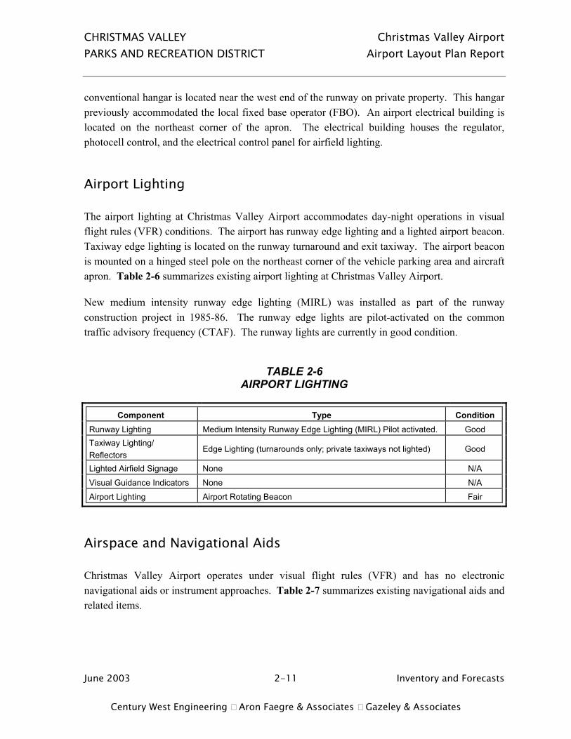
Airport Lighting
The airport lighting at Christmas Valley Airport accommodates day-night operations in visual flight rules (VFR) conditions. The airport has runway edge lighting and a lighted airport beacon. Taxiway edge lighting is located on the runway turnaround and exit taxiway. The airport beacon is mounted on a hinged steel pole on the northeast corner of the vehicle parking area and aircraft apron. Table 2-6 summarizes existing airport lighting at Christmas Valley Airport.
New medium intensity runway edge lighting (MIRL) was installed as part of the runway construction project in 1985-86. The runway edge lights are pilot-activated on the common traffic advisory frequency (CTAF). The runway lights are currently in good condition.
TABLE 2-6
AIRPORT LIGHTING
Component Type Condition Runway Lighting Medium Intensity Runway Edge Lighting (MIRL) Pilot activated. Good Taxiway Lighting/ Reflectors
Edge Lighting (turnarounds only; private taxiways not lighted) Good
Lighted Airfield Signage None N/A
Visual Guidance Indicators None N/A
Airport Lighting Airport Rotating Beacon Fair
Airspace and Navigational Aids
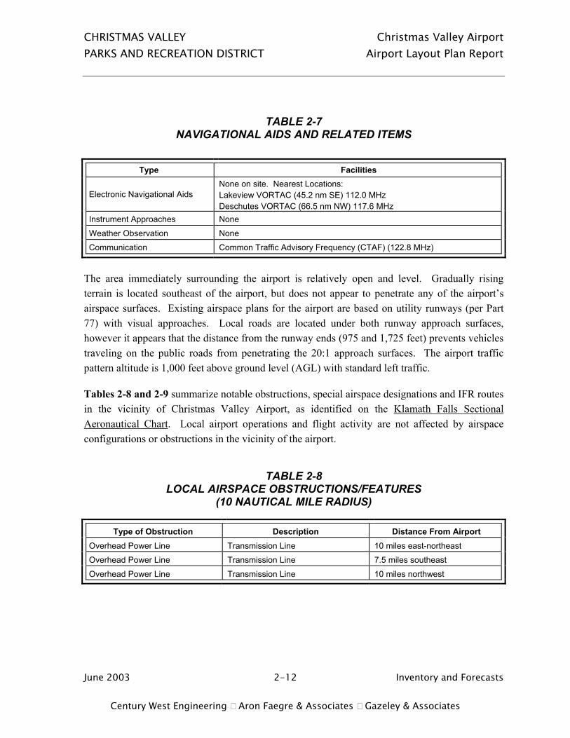
Christmas Valley Airport operates under visual flight rules (VFR) and has no electronic navigational aids or instrument approaches. Table 2-7 summarizes existing navigational aids and related items.
CHRISTMAS VALLEY Christmas Valley Airport PARKS AND RECREATION DISTRICT Airport Layout Plan Report
June 2003 2-12 Inventory and Forecasts Century West Engineering Aron Faegre & Associates Gazeley & Associates
TABLE 2-7 NAVIGATIONAL AIDS AND RELATED ITEMS
Type Facilities
Electronic Navigational Aids None on site. Nearest Locations: Lakeview VORTAC (45.2 nm SE) 112.0 MHz Deschutes VORTAC (66.5 nm NW) 117.6 MHz
Instrument Approaches None
Weather Observation None
Communication Common Traffic Advisory Frequency (CTAF) (122.8 MHz)
The area immediately surrounding the airport is relatively open and level. Gradually rising terrain is located southeast of the airport, but does not appear to penetrate any of the airport’s airspace surfaces. Existing airspace plans for the airport are based on utility runways (per Part 77) with visual approaches. Local roads are located under both runway approach surfaces, however it appears that the distance from the runway ends (975 and 1,725 feet) prevents vehicles traveling on the public roads from penetrating the 20:1 approach surfaces. The airport traffic pattern altitude is 1,000 feet above ground level (AGL) with standard left traffic.
Tables 2-8 and 2-9 summarize notable obstructions, special airspace designations and IFR routes in the vicinity of Christmas Valley Airport, as identified on the Klamath Falls Sectional Aeronautical Chart. Local airport operations and flight activity are not affected by airspace configurations or obstructions in the vicinity of the airport.
TABLE 2-8 LOCAL AIRSPACE OBSTRUCTIONS/FEATURES
(10 NAUTICAL MILE RADIUS)
Type of Obstruction Description Distance From Airport Overhead Power Line Transmission Line 10 miles east-northeast
Overhead Power Line Transmission Line 7.5 miles southeast
Overhead Power Line Transmission Line 10 miles northwest

CHRISTMAS VALLEY Christmas Valley Airport PARKS AND RECREATION DISTRICT Airport Layout Plan Report
June 2003 2-13 Inventory and Forecasts Century West Engineering Aron Faegre & Associates Gazeley & Associates
TABLE 2-9
AIRSPACE/INSTRUMENT ROUTES
Airspace Item Description Location
Low Altitude Enroute Airway Victor 165 – 9,500 feet mean sea level minimum enroute altitude (MEA)
7 nautical miles southwest. Connects Lakeview and Deschutes VORTACs on a 143-323 degree course.
Military Training Route IR 342 (surface upward) 4 miles west.
Military Training Route VR 1353 (surface upward) 5 miles west.
Military Operations Area (MOA) Juniper South (11,000 MSL Floor upward to FL180) & Low (300 feet above ground level (AGL) to FL180)
7 miles east.
Military Operations Area (MOA) Juniper North (11,000 MSL Floor upward to FL180) & Low (300 feet above ground level (AGL) to FL180)
10 miles northeast.
Airport (Table Rock) Private 3,300-foot airstrip 8 miles west.
AIRPORT SUPPORT FACILITIES/SERVICES
Aircraft Fuel
There is no aviation gasoline (AVGAS) or jet fuel currently available for sale at the airport. Fuel service was provided for many years, until 1996 when the local fixed based operator (FBO) closed. When last in operation, the FBO maintained two 8,000-gallon (estimated capacity) above-ground fuel storage tanks located on the east side of their hangar. The tanks and dispensing equipment remain in place but are not currently in use.
Surface Access and Vehicle Parking
Vehicle access to the airport apron and hangar areas is provided by Christmas Valley Road, which runs east-west connecting with U.S. Route 395. The only designated vehicle parking on the airport is a paved area located adjacent to north side of the aircraft apron. There are also several private roads/driveways connecting to Christmas Valley Road that connect directly to private taxiways entering the airport. The wire fence located along the airport’s northern property line has gates at most of the taxiway entrances to the airport.
CHRISTMAS VALLEY Christmas Valley Airport PARKS AND RECREATION DISTRICT Airport Layout Plan Report
June 2003 2-14 Inventory and Forecasts Century West Engineering Aron Faegre & Associates Gazeley & Associates
Fencing
The airport has limited wire fencing around most of its property boundary. Local airport users indicate that wildlife (primarily deer) are present at the airport and occasionally need to be cleared from the runway or taxiways in order for aircraft to operate.
Utilities
Local utility providers include Pacific Power & Light (electric) and CenturyTel (telephone). The airport has an electrical building located near the runway and adjacent to Christmas Valley Road that houses controls for airfield lighting and the airport beacon Electricity is supplied to the airport electrical building by overhead power lines that run along Christmas Valley Road. There are no restrooms at the airport and phone service is not provided.
Land Use Planning and Zoning
The Christmas Valley Airport is located in Lake County, Oregon, in the unincorporated community of Christmas Valley. Lake County has planning and zoning jurisdiction over the site and its surroundings. The airport property is zoned Lake County Public Facilities (P-F), which allows airport uses outright. Christmas Valley / Wagontire Road is a county right-of-way, which is located north of the airport. Lands located between the north side of the airport and the road are in residential and commercial zoning. North of the road, the area is primarily open space range use (agriculture zoning). The primary zoning in the areas immediately south of the airport is residential. The areas located under the runway approaches are primarily zoned agriculture (east) and commercial (west). The County’s Airport Approach Combining (A-A) Zone extends off either runway end, and is intended to protect against incompatible land uses directly aligning with those areas. The existing airport overlay zones will be reviewed in more detail in Chapter Six to determine whether they fully comply with the requirements defined in Oregon’s Revised Statutes Chapters 836.600-630. No significant issues or concerns have arisen during these investigations relative to the compatibility of existing or foreseeable land uses on property neighboring this facility. Please see Chapter Six of this report for further discussions regarding land use compatibility related to operations of Christmas Valley Airport. Table 2-10 summarizes the existing land uses and zoning in the vicinity of the airport.

CHRISTMAS VALLEY Christmas Valley Airport PARKS AND RECREATION DISTRICT Airport Layout Plan Report
June 2003 2-15 Inventory and Forecasts Century West Engineering Aron Faegre & Associates Gazeley & Associates
TABLE 2-10
AIRPORT VICINITY LAND USE AND ZONING
Land Use Zoning Airport Site: Lake County Public Facilities (P-F) North: Vacant Land, Wagontire Road Open Space, Single Family Residential
Lake County Rural Residential (R-1), Commercial (C-1), Agriculture (A) R-1
South: Residential and Open Space
R-1
East: Open Space, Single Family Residential
A R-1
West: Single Family Residential Burned Out Gas Station
C-1
Northwest: Various Limited Commercial Uses, Community of Christmas Valley
C-1
Airport Service Area
The airport service area refers to the area surrounding an airport that is directly affected by the activities at that airport. Normally a 30 or 60-minute surface travel time is used to approximate the boundaries of a service area for a small general aviation airport. There are only a few public use airports located within a 60-mile (air) radius of Christmas Valley and most of these have drive times of an hour or more. Table 2-11 lists the public use airports in the vicinity of Christmas Valley.
TABLE 2-11 PUBLIC USE AIRPORTS IN VICINITY
(WITHIN 60 NAUTICAL MILES)
Airport Location Runway
Dimension (feet) Runway Lighting
Surface Fuel
Alkali State 32 NM east-southeast 6,100 x 150 No Gravel No
Paisley 31 NM south-southeast 4,300 x 60 Yes Asphalt No
Silver Lake USFS 20 NM southwest 3,000 x 55 No Gravel No
Beaver Marsh 51 NM west-southwest 4,500 x 60 No Dirt No
Sunriver 52 NM northwest 5,455 x 70 Yes Asphalt Yes

CHRISTMAS VALLEY Christmas Valley Airport PARKS AND RECREATION DISTRICT Airport Layout Plan Report
June 2003 2-16 Inventory and Forecasts Century West Engineering Aron Faegre & Associates Gazeley & Associates
Bend Municipal 56 NM northwest 5,005 x 75 Yes Asphalt Yes
AVIATION ACTIVITY AND FORECASTS
Historical Aviation Activity
Recent aviation activity data for Christmas Valley Airport is limited to state aviation system plan inventory and forecast documents, FAA forecasts and measurements taken as part of the Acoustical Activity Counting program, conducted by the Oregon Department of Aviation (ODA). The most recent airport-specific planning documents for Christmas Valley were prepared in the early 1980’s, as part of an airport master plan and environmental assessment. Existing activity was estimated at 20-based aircraft and 4,200 annual operations in the 1983 Airport Development Plan. Acoustical activity counts are available for Christmas Valley Airport for the years 1981, 1986 and 1992. The three activity counts reflect a decline in operations (-81%) over the 11-year period. The number of aircraft based at the airport has declined by about half during this period. A summary of historical activity is provided in Table 2-12. The most recent activity count for the airport was 600 annual operations in 1992. Available data indicates that there were approximately 17-based aircraft at the airport in 1992. Local airport users indicate that fuel was available at the airport during that time. Since that time, the number of based aircraft has fallen by about one-half and aviation fuel has not been available for sale since 1996. These factors suggest that the 1992 estimate may have understated activity, although that cannot be documented. However, based on current conditions (nine based aircraft, no aviation fuel, and a modest amount of itinerant traffic), the previous estimate of 600 may be relatively close to current airport activity. As noted earlier, recent activity at Christmas Valley Airport declined during a period of strong population growth within the community. These opposite trends suggest that while changes in population (historic and future) may be expected to affect airport activity, other airport-specific factors will often be more significant. However, it is possible that the decline in airport activity may have been even greater had local population also declined during this period.
Based on all available information, it appears that the dampening effect of the prolonged absence of fuel and services has been fully reflected in airport activity, which has stabilized at relatively low levels in recent years. Although a further decline in activity would not be indicated, it is reasonable to expect that these factors will continue to constrain the rate of growth for future

CHRISTMAS VALLEY Christmas Valley Airport PARKS AND RECREATION DISTRICT Airport Layout Plan Report
June 2003 2-17 Inventory and Forecasts Century West Engineering Aron Faegre & Associates Gazeley & Associates
airport activity. It appears that the existing core group of airport users is not significantly deterred by the absence of fuel and services.
If conditions remain unchanged, this segment of activity may be expected to increase at a modest rate during the planning period. Given the current uncertainty associated with these local conditions, aviation activity can reasonably be expected to experience modest growth above current levels. However, if fuel and services became available during the planning period, airport activity may respond positively to the events both in terms of attracting new based aircraft and itinerant activity. Based on this, it will be particularly important to provide adequate development reserves to accommodate activity that may exceed the current modest projections.
To draw a broad historical comparison, the data for the eight separate years available were totaled and divided to provide a simple average. This information is included in Table 2-12 and provides a reasonable basis for evaluating historic and current activity ratios. Current activity is estimated at 1,350 operations, based on recent historical utilization ratios and the current count of nine based aircraft. A review of the relationships between local population and airport activity is summarized in Table 2-13. This information illustrates that the population-based airport activity ratios have changed significantly over the last twenty years based on the decline in airport activity and the increase in local population. Since 1980, the number of annual aircraft operations per capita has declined from around 4 to 1, and the number of residents per based aircraft has increased from around 50 to 125. Table 2-14 summarizes current based aircraft at the airport, all of which are single-engine piston.
TABLE 2-12 HISTORICAL AVIATION ACTIVITY
Year Based Aircraft
Aircraft Operations
Avg. Operations per Based Aircraft Data Source
1981 15 3,232 215 Rens Activity Counts OASP Estimate (based aircraft)
1983 20 4,200 210 Master Plan Estimate
1986 10 2,093 209 Rens Activity Counts OASP Estimate (based aircraft)
1989 8 1,500 188 OASP Estimate
1990 13 1,200 92 OASP Estimate
1992 17 600 35 Rens Activity Counts OASP Estimate (based aircraft)
1994 7 600 86 OASP Estimate
2002 9 1,350 150 Updated Based Aircraft Inventory User/Century West Estimates

CHRISTMAS VALLEY Christmas Valley Airport PARKS AND RECREATION DISTRICT Airport Layout Plan Report
June 2003 2-18 Inventory and Forecasts Century West Engineering Aron Faegre & Associates Gazeley & Associates
8-Period Average
12.4 1,847 148 Straight Average Over Eight Separate Years
TABLE 2-13
LOCAL POPULATION/AVIATION ACTIVITY RATIOS
Year Population Based Aircraft
Aircraft Operations
Ratio of Aircraft Operations Per Capita
Ratio of Christmas Valley Population Per Based Aircraft (BAC)
1980 766 15 3,232 4.2 ops per capita 51.1 residents per BAC
1990 731 13 1,200 1.6 ops per capita 56.2 residents per BAC
2000 1,128 9 1,350 1.2 ops per capita 125.3 residents per BAC
3-Period Average
875 12.3 1,927 2.3 ops per capita 77.5 residents per BAC
TABLE 2-14
2002 BASED AIRCRAFT
Aircraft Type Quantity Single Engine 9
Multi-Engine 0
Other 0
Total 9
Source: Updated airport inventory (December 2002)
Forecasts of Activity
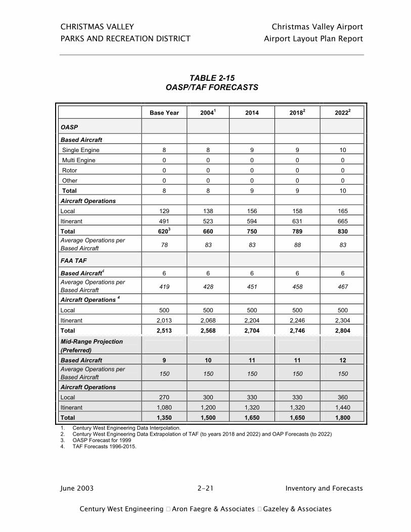
The aviation forecasts contained in the Christmas Valley Airport Improvement Plan (M.R. Miner & Associates, 1984), projected 28 based aircraft and 8,400 annual operations for the airport in the year 2003, considerably higher than current or recent activity. Although these forecasts provide an interesting historical reference, they are not useful for predicting future activity-based needs at Christmas Valley Airport. Table 2-15 summarizes the forecasts of based aircraft and aircraft operations (takeoffs and landings) developed through statewide aviation system plans and the Federal Aviation Administration’s Terminal Area Forecast (TAF) program. These forecasts reflect low growth rates, which are typical of lower activity general aviation airports in Oregon.

CHRISTMAS VALLEY Christmas Valley Airport PARKS AND RECREATION DISTRICT Airport Layout Plan Report
June 2003 2-19 Inventory and Forecasts Century West Engineering Aron Faegre & Associates Gazeley & Associates
Based Aircraft
The 1997 OASP based aircraft forecasts range from 7 aircraft (1994) to 9 aircraft (2014) for Christmas Valley. The 2000 Oregon Aviation Plan, projects 9-based aircraft for Christmas Valley in the year 2018. The TAF projects an unchanged 6-based aircraft through 2015. For the purposes of forecasting, these existing projections were extended out to the end of the current ALP twenty-year planning period (2022) using the same average annual growth rates.
Future improvements in airport facilities or new hangar space could stimulate activity. However, at Christmas Valley, the largest portion of the recent decline in based aircraft occurred after the new runway was constructed in 1985, which suggests that the quality of facilities may not have been a key factor in the trend. Similarly, there are no apparent barriers to the development of the 40 private residence-hangar lots located on the north edge of the airport.
As noted earlier, local pilots who attended the joint planning conference for this project indicated that there was a significant reduction in aircraft operations after 1996 when fuel service and other FBO type services ceased to be provided. The individual who had provided fuel service also organized fly-ins and provided training and other flying services. The availability of fuel and the involvement of an individual or group committed to promoting aviation-related activities seem to be important factors affecting operations levels at the airport. It is generally recognized that the loss of aviation fuel has adversely affected aircraft activity at the airport in recent years. However, to this point there has been no successful effort to resume aviation fuel sales at the airport.
Based on current conditions, the existing OASP based aircraft forecast provides a reasonable projection of growth and is recommended as the preferred forecast of based aircraft for the ALP Report. Note: the OASP forecasts were subsequently adjusted to reflect the current base year (2002) based aircraft total of nine aircraft.
The large number of undeveloped hangar parcels adjacent to the airport suggests that the potential exists for the number of based aircraft to increase significantly in the future. Although there is no immediate indication that a large number of new hangars will be developed in the near future, development reserves should be maintained to accommodate any increased demand for on-airport facilities that would be associated with this potential development.

CHRISTMAS VALLEY Christmas Valley Airport PARKS AND RECREATION DISTRICT Airport Layout Plan Report
June 2003 2-20 Inventory and Forecasts Century West Engineering Aron Faegre & Associates Gazeley & Associates
Aircraft Operations
The OASP and FAA TAF aircraft operations forecasts reflect low annual growth rates (less than one percent). The OASP and TAF split between local traffic (touch and go, local traffic area) (20 percent) and itinerant traffic (80 percent) appears to be reasonable based on current conditions.
The OASP and TAF projections both reflect modest overall activity levels. However, the forecasts reflect significantly different aircraft utilization levels. As noted earlier, the existing ratio of operations per based aircraft is estimated at approximately 150. The OASP projections reflect a ratio of 83 operations per based aircraft and the TAF reflects a ratio of 428 to 467, when extrapolated to 2022.
For the purposes of providing updated forecasts, it is recommended that a mid-range projection be developed based on the OASP based aircraft forecast with an operations ratio of 150, which is consistent with the airport’s historical average. This projection is presented in Table 2-15 and is recommended for use as the preferred forecast. As noted above, the operations projection was adjusted slightly to reflect the updated (2002) based aircraft count.
Airfield Capacity
Airfield capacity for a single runway without a parallel taxiway normally ranges from 30 to 60 operations per hour. Based on forecast activity, existing runway capacity at Christmas Valley Airport is considered to be adequate through the planning period.
CHRISTMAS VALLEY Christmas Valley Airport PARKS AND RECREATION DISTRICT Airport Layout Plan Report
June 2003 2-21 Inventory and Forecasts Century West Engineering Aron Faegre & Associates Gazeley & Associates
TABLE 2-15
OASP/TAF FORECASTS
Base Year 20041 2014 20182 20222
OASP
Based Aircraft
Single Engine 8 8 9 9 10
Multi Engine 0 0 0 0 0
Rotor 0 0 0 0 0
Other 0 0 0 0 0
Total 8 8 9 9 10
Aircraft Operations
Local 129 138 156 158 165
Itinerant 491 523 594 631 665
Total 6203 660 750 789 830 Average Operations per Based Aircraft 78 83 83 88 83
FAA TAF
Based Aircraft4 6 6 6 6 6 Average Operations per Based Aircraft 419 428 451 458 467
Aircraft Operations 4
Local 500 500 500 500 500
Itinerant 2,013 2,068 2,204 2,246 2,304
Total 2,513 2,568 2,704 2,746 2,804
Mid-Range Projection (Preferred)
Based Aircraft 9 10 11 11 12 Average Operations per Based Aircraft 150 150 150 150 150
Aircraft Operations
Local 270 300 330 330 360
Itinerant 1,080 1,200 1,320 1,320 1,440
Total 1,350 1,500 1,650 1,650 1,800 1. Century West Engineering Data Interpolation. 2. Century West Engineering Data Extrapolation of TAF (to years 2018 and 2022) and OAP Forecasts (to 2022) 3. OASP Forecast for 1999 4. TAF Forecasts 1996-2015.

CHRISTMAS VALLEY Christmas Valley Airport PARKS AND RECREATION DISTRICT Airport Layout Plan Report
June 2003 3-1 Facility Requirements Century West Engineering Aron Faegre & Associates Gazeley & Associates
CHAPTER THREE AIRPORT FACILITY REQUIREMENTS
INTRODUCTION
This chapter uses the results of the inventory and forecasts conducted in Chapter Two and established planning criteria to determine the airport’s airside and landside facility requirements through the twenty-year planning period. Airside facilities include runways, taxiways, navigational aids and lighting systems. Landside items include hangars, fixed base operator (FBO) facilities, aircraft parking apron, aircraft fuel storage and dispensing facilities, automobile parking, utilities and surface access.
The facility requirements evaluation is used to identify the adequacy or inadequacy of existing airport facilities and identify any new facilities required during the current twenty-year planning period based on forecast demand. Options for providing these facilities will be evaluated in Chapter Four to determine the most cost effective and efficient means for implementation.
As noted in the previous chapter, activity at Christmas Valley Airport is low and has declined from the activity peaks experienced in the mid 1980s. It is widely believed among local residents that the elimination of aviation fuel sales has significantly affected activity levels at the airport. According to available data, the number of based aircraft has declined from around 20 in 1983 to the current estimate of 8 aircraft. Aircraft operations have not exceeded 1,500 since the late 1980s and the most recent ODA activity count for the airport was 600 operations, generated in 1992. The updated forecasts of aviation activity projects an increase in based aircraft from 9 to 12 over the next twenty years (+3 aircraft) with an operations forecast to increase to approximately 1,800 operations during the same period.
Eight of the nine aircraft currently based at the airport are stored in hangars off airport property. One aircraft (inactive) is parked on the apron. Based on the modest growth projections for the airport, the current level of facility utilization, and the capacity/capabilities of existing facilities, the majority of facility requirements are associated with maintaining current facilities and capabilities. However, despite modest projections of growth, it is difficult to predict how

CHRISTMAS VALLEY Christmas Valley Airport PARKS AND RECREATION DISTRICT Airport Layout Plan Report
June 2003 3-2 Facility Requirements Century West Engineering Aron Faegre & Associates Gazeley & Associates
quickly demand for facilities can change. For this reason, landside development reserves (aircraft parking, hangars, etc.) should be established to accommodate unanticipated demand and to also protect the relatively small amount of remaining developable land on the airport.
One unique feature of the airfield configuration at Christmas Valley Airport is the number of existing private taxiways that have direct access to the runway. Although existing and forecast air traffic levels would not typically require development of parallel taxiway for capacity improvement, the existing aircraft access to the runway does present safety concerns. In addition, the potential development of individual taxiways from each of the vacant residence/hangar lots located north of the runway could create significant safety concerns for the airport and users. As part of the development of a north side parallel taxiway, the existing hangar access taxiway connections would terminate at the parallel taxiway; a limited number of taxiways connections would be provided between the runway and parallel taxiway. Adding a parallel taxiway would also eliminate the need for aircraft to back-taxi on the runway, which provides additional safety benefits for users.
AIRPORT PLANNING OVERVIEW
Runway 7/25 was reconstructed and paved in 1985 based on standards comparable to the current Airplane Design Group I (ADG I) (for runways serving small aircraft exclusively).5 Runway 7/25 was planned as a utility (visual) runway and the design aircraft was identified as a light twin aircraft, weighing less than 12,500 pounds. No significant changes in the type of aircraft using the airport have occurred since the last ALP update was completed in 1984, just prior to the runway reconstruction.
LAND UTILIZATION
The airport consists of approximately 68 acres, which includes the airside area (runway and its protected areas) and the landside area located near the northwest corner of the airport. Table 3-1 summarizes existing airport land uses based on current and previously planned airfield configurations.
In its current configuration, the runway and most required clear areas associated with the airside facilities are contained within airport property. The runway protection zones (RPZ) for both runway ends extend beyond airport property and have public roads located within their 5 See Page 3-6 for a detailed description of FAA airport planning/design criteria

CHRISTMAS VALLEY Christmas Valley Airport PARKS AND RECREATION DISTRICT Airport Layout Plan Report
June 2003 3-3 Facility Requirements Century West Engineering Aron Faegre & Associates Gazeley & Associates
boundaries. The airside portion of the airport accounts for approximately 63 acres (93% of the total airport area). This area is adequate to accommodate a parallel taxiway on the north side of the runway to serve existing and future landside developments. A review of previous recommendations for property acquisition or easements will be completed based on the configuration of facilities depicted on the updated airport layout plan.
The landside area of the airport consists of approximately 5 acres, of which nearly half is currently developed (apron, vehicle parking, access, etc.). The remaining undeveloped landside areas consist of approximately 2 acres located on the west and east sides of the apron. Although this is very limited amount of land, the historical development of hangars off airport property, combined with modest growth projections, suggests that the remaining land area will be adequate to accommodate facility demand through the current planning period and beyond. However, due to the small amount of developable acreage, it is important that development in this area be limited to aviation related uses.
TABLE 3-1 AIRPORT LAND USE CONFIGURATION
CHRISTMAS VALLEY AIRPORT
Existing Land Use Acreage1 Percentage of Total Airport
Property Airside (Developed or Reserved) Runway, Parallel Taxiway Reserve, Runway Protection Zones, Object Free Area, Runway Safety Area, Obstacle Free Zone, Primary Surface.
63 92%
Landside (Developed or Reserved) Aircraft Apron, Hangar Area, Vehicle Parking, Access Roads, Undeveloped Land.
5 8%
Total 681 100%
1. Property Map, Exhibit “A” Christmas Valley Airport, 1985; subsequent property acquisition identified at west end of airport.
AIRSPACE
The airspace surfaces depicted on the 1984 Approach and Clear Zone Plan6 were based on utility runways and visual approaches. The airport is surrounded by relatively flat terrain with rising terrain located several miles from the airport. No areas of terrain penetration to the airspace surfaces were depicted on the 1984 plan and none were noted in the updated review. The 1984 plan did not identify any other airspace obstructions such as structures. However, based on a
6 Christmas Valley Airport – Airport Airspace Plan, Miner Associates (1984)
CHRISTMAS VALLEY Christmas Valley Airport PARKS AND RECREATION DISTRICT Airport Layout Plan Report
June 2003 3-4 Facility Requirements Century West Engineering Aron Faegre & Associates Gazeley & Associates
review of available aerial photography, it appears that several structures have been constructed in close proximity to the runway in recent years. It is not clear whether airspace evaluations have consistently been completed as part of the local land use review or issuance of building permits for construction in the vicinity of the airport, although a record of such reviews was not located during this project.
To provide verifiable information, a baseline obstruction survey should be conducted to determine whether any existing structures penetrate FAR Part 77 airspace surfaces. If an obstruction exists, the item should be lighted or the obstruction removed, if feasible. The responsibility to ensure that obstructions are identified and adequately addressed rests with the airport sponsor. All future construction in the vicinity of the airport should include a coordinated local, state and federal review to ensure that no obstructions are created as a result of the project. Nearby structures will be depicted on the updated airspace plan and roof height elevations will be estimated if surveyed elevations are not available.
Under 14 Code of Federal Regulations (14 CFR, part 77), the sponsor who proposes new construction or alteration of an existing structure in the vicinity of an airport is responsible for notifying the FAA through submittal of FAA Form 7460-1 Notice of Proposed Construction or Alteration. However, in order to protect its interests, the airport sponsor (Christmas Valley Parks and Recreation District) should require that a completed 7460 form and the FAA written response be provided as a condition of issuing airport access agreements for off-airport hangars or approving leases for construction of facilities on airport property. In addition, Lake County planning and building officials should require that an applicant demonstrate that the 7460 form has been properly coordinated with FAA, the Oregon Department of Aviation and the county prior to issuing local permits. A sample FAA Form 7460-1 and instructions for its completion is provided in Appendix 3. Based on the length of the runway at Christmas Valley Airport, the 7460 review area extends outward at a slope of 100 to 1 for a horizontal distance of 20,000 feet from the nearest point on the runway.
The airspace features described in Chapter Two (IFR airways, military training routes, etc.) do not affect local airport operation. The airspace structure surrounding Christmas Valley Airport is uncomplicated and is not expected to constrain future airport development or operation.
INSTRUMENT APPROACH CAPABILITIES
Christmas Valley Airport does not currently have a published instrument approach procedure (IAP). As noted earlier, previous airfield/airspace planning for Christmas Valley has been based on visual approach surfaces, as defined by FAR Part 77. The development of an instrument
CHRISTMAS VALLEY Christmas Valley Airport PARKS AND RECREATION DISTRICT Airport Layout Plan Report
June 2003 3-5 Facility Requirements Century West Engineering Aron Faegre & Associates Gazeley & Associates
approach was not included among the priorities identified by airport users during the planning conference held at the outset of this project.
Recent changes in FAA standards for establishing day/night instrument approaches at small airports now require considerably larger clear areas surrounding the runway than are currently available at Christmas Valley Airport. For this reason, accommodating an instrument approach that is authorized for day and night use for Runway 7/25 is not feasible without property acquisition to the north and/or shifting the road located along the south side of the airport to provide the required clear areas.
Based on the limited practicality of pursuing the necessary property acquisition and roadway relocation, it is recommended that Runway 7/25 and the associated airspace surfaces continue to be planned based on visual approaches. Development of a future nonprecision instrument approach that is authorized for daytime use only can be accommodated within the existing airfield development and airspace configuration.
AIRPORT DESIGN STANDARDS
The selection of the appropriate design standards for the development of airfield facilities is based primarily upon the characteristics of the aircraft that are expected to use the airport. The most critical characteristics are the approach speed and wingspan of the design aircraft anticipated for the airport. Federal Aviation Administration (FAA) Advisory Circular (AC) 150/5300-13, Airport Design, serves as the primary reference in planning airfield facilities. FAR Part 77, Objects Affecting Navigable Airspace, defines airport imaginary surfaces, which are established to protect the airspace immediately surrounding a runway. The airspace and ground areas surrounding a runway should be free of obstructions (i.e., structures, parked aircraft, terrain, trees, etc.) to the greatest extent possible.
FAA Advisory Circular 150/5300-13 groups aircraft into five categories based upon their approach speed. Categories A and B include small propeller aircraft, some smaller business jet aircraft, and some larger aircraft with approach speeds of less than 121 knots. Categories C, D, and E consist of the remaining business jets as well as larger jet and propeller aircraft generally associated with commercial and military use; these aircraft have approach speeds of 121 knots or more. The advisory circular also establishes six aircraft design groups, based on the physical size (wingspan) of the aircraft. The categories range from Airplane Design Group (ADG) I, for aircraft with wingspans of less than 49 feet, to ADG VI for the largest commercial and military aircraft. A summary of typical aircraft and their respective design categories is presented in Table 3-2.

CHRISTMAS VALLEY Christmas Valley Airport PARKS AND RECREATION DISTRICT Airport Layout Plan Report
June 2003 3-6 Facility Requirements Century West Engineering Aron Faegre & Associates Gazeley & Associates
The 1984 Airport Improvement Plan7 recommended that facilities at Christmas Valley be planned based on Basic Utility II design standards, which are comparable to the current Aircraft Approach Category B and Airplane Design Group I (B-I). All locally based aircraft and the majority of itinerant aircraft using the airport on a regular basis are classified as small aircraft, weighing less than 12,500 pounds.
Based on a review of historic, existing and forecast air traffic; site considerations; the design of existing facilities; and prior planning recommendations, it is recommended that the “small aircraft exclusively” subcategory of Airplane Design Group I be used as the appropriate planning criteria for Christmas Valley Airport. For comparison, airfield design standards for both ADG I and ADG I (small aircraft exclusively) are presented in Table 3-3. A summary of Christmas Valley Airport’s current compliance with the design standards is presented in Table 3-4. A detailed description of the applicable airport design standards is presented later in this chapter.
7 Airport Improvement Plan Christmas Valley Airport (M.R. Miner Associates, January 1984).
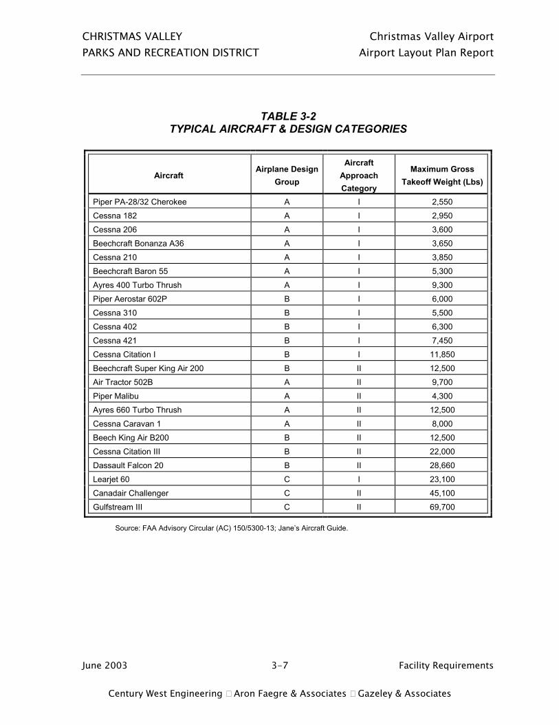
CHRISTMAS VALLEY Christmas Valley Airport PARKS AND RECREATION DISTRICT Airport Layout Plan Report
June 2003 3-7 Facility Requirements Century West Engineering Aron Faegre & Associates Gazeley & Associates
TABLE 3-2 TYPICAL AIRCRAFT & DESIGN CATEGORIES
Aircraft Airplane Design
Group
Aircraft Approach Category
Maximum Gross Takeoff Weight (Lbs)
Piper PA-28/32 Cherokee A I 2,550
Cessna 182 A I 2,950
Cessna 206 A I 3,600
Beechcraft Bonanza A36 A I 3,650
Cessna 210 A I 3,850
Beechcraft Baron 55 A I 5,300
Ayres 400 Turbo Thrush A I 9,300
Piper Aerostar 602P B I 6,000
Cessna 310 B I 5,500
Cessna 402 B I 6,300
Cessna 421 B I 7,450
Cessna Citation I B I 11,850
Beechcraft Super King Air 200 B II 12,500
Air Tractor 502B A II 9,700
Piper Malibu A II 4,300
Ayres 660 Turbo Thrush A II 12,500
Cessna Caravan 1 A II 8,000
Beech King Air B200 B II 12,500
Cessna Citation III B II 22,000
Dassault Falcon 20 B II 28,660
Learjet 60 C I 23,100
Canadair Challenger C II 45,100
Gulfstream III C II 69,700
Source: FAA Advisory Circular (AC) 150/5300-13; Jane’s Aircraft Guide.

CHRISTMAS VALLEY Christmas Valley Airport PARKS AND RECREATION DISTRICT Airport Layout Plan Report
June 2003 3-8 Facility Requirements Century West Engineering Aron Faegre & Associates Gazeley & Associates
TABLE 3-3 AIRPORT DESIGN STANDARDS SUMMARY
(DIMENSIONS IN FEET)
Standard Existing
Runway 7/25 ADG I1
Small Aircraft Exclusively ADG I1
A&B Aircraft
Runway Length 5,200 4,030/5,2602 4,030/5,2602
Runway Width 60 60 60
Runway Shoulder Width 10 10 10
Runway Safety Area Width 120 120 120
Runway Safety Area Length (Beyond Rwy End) 240 240 240
Obstacle-Free Zone 250 250 250
Object Free Area Width 250 250 400
Object Free Area Length (Beyond Runway End) 240 240 240
Primary Surface Width 250 2501 5001
Primary Surface Length (Beyond Runway End) 200 2001 2001
Runway Protection Zone Length 1,000 1,0001 1,0001
Runway Protection Zone Inner Width 250 2501 5001
Runway Protection Zone Outer Width 450 4501 7001 Runway Centerline to:
Parallel Taxiway Centerline Aircraft Parking Area Building Restriction Line
Taxiway Width Taxiway Shoulder Width Taxiway Safety Area Width Taxiway Object Free Area Width Taxiway Centerline to Fixed/Movable Object
n/a
none identified 250
(north side only)6
255 varies varies varies varies
150
125/194.53 2514
25 10 49 89
44.5
225
200/269.53 3764
25 10 49 89
44.5
Notes: 1. Utility runways (Per FAR Part 77); all other dimensions reflect nonprecision runways with not lower than 3/4-statute mile
approach visibility minimums (per AC 150/5300-13, Change 7). RPZ dimensions based on visual and not lower than 1-mile approach visibility minimums for “small aircraft exclusively”/ “Category A & B Aircraft.”
2. Runway length required to accommodate 75 and 95 percent of General Aviation Fleet 12,500 pounds or less. 80 degrees F, 1-foot change in runway centerline elevation
3. Standard distance per AC150/5300-13 & distance required to accommodate a 10-foot aircraft tail height (at the APL) beneath the 7:1 Transitional Surface with an ADG I/ADG I (small) parallel taxiway object free area.
4. Distance required to accommodate an 18-foot structure (at the BRL) beneath the 7:1 Transitional Surface for runways with visual approaches or nonprecision instrument approaches with circle-to-land procedure; also protects ADG I/ ADG I (small) parallel taxiway object free area.
5. Existing width of West Taxiway. 6. As depicted on 1984 ALP.

CHRISTMAS VALLEY Christmas Valley Airport PARKS AND RECREATION DISTRICT Airport Layout Plan Report
June 2003 3-9 Facility Requirements Century West Engineering Aron Faegre & Associates Gazeley & Associates
TABLE 3-4
RUNWAY 7/25 COMPLIANCE WITH FAA DESIGN STANDARDS
Item Airplane Design
Group I (Small Aircraft Exclusively)1
Airplane Design Group I
(A&B Aircraft)1 Runway Safety Area Yes Yes
Runway Object Free Area Yes No3
Runway Obstacle Free Zone Yes Yes
Taxiway Safety Area Yes4 No6
Taxiway Object Free Area Yes4 No6
Taxilane Object Free Area No7 No3
Building Restriction Line Yes No2
Aircraft Parking Line Yes4 No3
Runway Protection Zones No5 No5
Runway-Parallel Taxiway Separation N/A
Yes (Future) N/A
No (Future)6 Runway Width Yes Yes
Runway Length Yes Yes
Runway Pavement Strength Yes Yes
Taxiway Width Yes Yes
Notes: 1. Runway design standards for visual runways and runways with not lower than ¾-statute mile approach visibility minimums. 2. Clearance required for 500-foot wide primary surface and 18-foot building under transitional surface. 3. Front section of main apron parking located within runway object free area, obstacle free zone, primary surface, and
transitional surface. 4. Assumes that front edge of apron would be converted into parallel taxiway as part of construction; new APL based
on ADG I (small) taxiway OFA separation of 44.5 feet from centerline. 5. Public roadways located within Runway 7 and 25 RPZ; structures located in Rwy 7 RPZ. 6. Insufficient airport property to meet FAA ADG I Taxiway separation, OFA and safety area requirements. 7. The taxilane clearance between tiedown rows on the main apron is less than the FAA-recommended 79 feet (39.5
feet from taxilane centerline).

CHRISTMAS VALLEY Christmas Valley Airport PARKS AND RECREATION DISTRICT Airport Layout Plan Report
June 2003 3-10 Facility Requirements Century West Engineering Aron Faegre & Associates Gazeley & Associates
Airport Design Standards Note: The following airport design standards are based on visual runways and runways with not lower than ¾ statute mile visibility minimums. For defining runway protection zones (RPZ), the visibility standard is “visual and not lower than 1-mile.” All references to the “standards” are based on these approach visibility assumptions, unless otherwise noted. (Per FAA Advisory Circular 150/5300-13, change 7). Existing and future Airport Design Standards are based on Airport Reference Code (ARC) B-I (small aircraft exclusively). FAR Part 77 airspace planning criteria based on “utility runways” with visual approaches. See Table 3-3 for recommended dimensions for all design standards.
Runway Safety Area (RSA)
The FAA defines runway safety area (RSA) as “A defined surface surrounding the runway prepared or suitable for reducing the risk of damage to airplanes in the event of an undershoot, overshoot, or excursion from the runway.” Runway safety areas are most commonly used by aircraft that inadvertently leave (or miss) the runway environment during landing or takeoff.
By FAA design standard, the RSA “shall be:
(1) cleared and graded and have no potentially hazardous ruts, humps, depressions, or other surface variations;
(2) drained by grading or storm sewers to prevent water accumulation;
(3) capable, under dry conditions, of supporting snow removal equipment, aircraft rescue and firefighting equipment, and the occasional passage of aircraft without causing structural damage to the aircraft; and
(4) free of objects, except for objects that need to be located in the runway safety area because of their function. Objects higher than 3 inches above grade should be constructed on low impact resistant supports (frangible mounted structures) of the lowest practical height with the frangible point no higher than 3 inches. Other objects such as manholes, should be constructed at grade. In no case should their height exceed 3 inches.”
The recommended transverse grade for the lateral RSA ranges between 1½ and 5 percent from runway shoulder edges. The recommended longitudinal grade for the first 200 feet of extended

CHRISTMAS VALLEY Christmas Valley Airport PARKS AND RECREATION DISTRICT Airport Layout Plan Report
June 2003 3-11 Facility Requirements Century West Engineering Aron Faegre & Associates Gazeley & Associates
RSA beyond the runway end is 0 to 3 percent. The remainder of the RSA must remain below the runway approach surface slope. The maximum negative grade is 5 percent. Limits on longitudinal grade changes are plus or minus 2 percent per 100 feet within the RSA. The ADG I (small) RSA is 120 feet wide and extends 240 feet beyond each runway end.
The RSA along the sides and beyond the ends of Runway 7/25 has been cleared and graded to meet FAA dimensional standards. The RSA appears to be free of physical obstructions and within grade standards. The runway edge lights and threshold lights located within the RSA are mounted on frangible supports (breakable coupling and disconnect plug) with a height of approximately 14 inches. Any future lighting (such as PAPI) located within the RSA will also need to meet FAA frangibility standards.
Local pilots have indicated that brush build-up along the runway is a regular maintenance problem. The airport sponsor should regularly clear the RSA of brush or other debris and periodically grade and compact the RSA to maintain FAA standards.
Runway Object Free Area (OFA)
Runway object free areas (OFA) are two-dimensional surfaces intended to be clear of ground objects that protrude above the runway safety area edge elevation. Obstructions within the OFA may interfere with aircraft flight in the immediate vicinity of the runway. The FAA defines the OFA clearing standard:
“The OFA clearing standard requires clearing the OFA of above ground objects protruding above the runway safety area edge elevation. Except where precluded by other clearing standards, it is acceptable to place objects that need to be located in the OFA for air navigation or aircraft ground maneuvering purposes and to taxi and hold aircraft in the OFA. Objects non-essential for air navigation or aircraft ground maneuvering purposes are not to be placed in the OFA. This includes parked airplanes and agricultural operations.”
The OFA meets the ADG I (small) dimensional standards (250 feet wide, extending 240 feet beyond each runway end) and appears to be free of physical obstructions. The airport sponsor should periodically inspect the OFA and remove any objects that protrude into the OFA.

CHRISTMAS VALLEY Christmas Valley Airport PARKS AND RECREATION DISTRICT Airport Layout Plan Report
June 2003 3-12 Facility Requirements Century West Engineering Aron Faegre & Associates Gazeley & Associates
Obstacle Free Zone (OFZ)
The OFZ is a plane of clear airspace extending upward to a height of 150 feet above runway elevation, which coincides with the FAR Part 77 horizontal surface elevation. The FAA defines the following clearing standard for the OFZ:
“The OFZ clearing standard precludes taxiing and parked airplanes and object penetrations, except for frangible visual NAVAIDs that need to located in the OFZ because of their function.”
The OFZ may include the runway OFZ, the inner-approach OFZ (for runways with approach lighting systems), and the inner-transitional OFZ (for runways with lower than ¾-statute mile approach visibility minimums. For Christmas Valley Airport, only the runway OFZ is required based on runway configuration and instrument approach capabilities. The FAA defines the runway OFZ as:
“The runway OFZ is a defined volume of airspace centered above the runway centerline. The runway OFZ is the airspace above a surface whose elevation at any point is the same as the elevation of the nearest point on the runway centerline. The runway OFZ extends 200 feet beyond each end of the runway.”
The standard OFZ for runways serving small aircraft is 250 feet wide. This dimension corresponds with visual or nonprecision instrument approaches (not lower than ¾ mile approach visibility minimums). By FAA definition “the OFZ clearing standard precludes taxiing and parked airplanes and object penetrations, except for frangible visual NAVAIDS that need to be located in the OFZ because of their function.” The OFZ for Runway 7/25 appears to be free of physical obstructions and meets the required dimensional standard.
Aircraft hold lines are located 125 feet from runway centerline on the west taxiway (apron access) and the east aircraft turnaround/holding area, which coincide with the outer edge of the OFZ. Approximately 40 feet of the east turnaround is located outside the marked hold lines, which allows aircraft to remain outside the OFZ. Aircraft holding at the west end of the runway are able to remain clear of the OFZ by using the adjacent apron.
Aircraft hold lines were not observed on the private taxiways accessing the runway from the north, although several of the taxiways are unpaved.
CHRISTMAS VALLEY Christmas Valley Airport PARKS AND RECREATION DISTRICT Airport Layout Plan Report
June 2003 3-13 Facility Requirements Century West Engineering Aron Faegre & Associates Gazeley & Associates
Taxiway Safety Area
With the exception of the west taxiway, which serves the aircraft apron, the existing taxiways at Christmas Valley Airport are private, providing access between the runway and adjacent hangars located off airport property. These taxiways vary in dimension and condition.
The west taxiway is located at the threshold of Runway 7 and serves the adjacent aircraft parking apron. The west taxiway appears to meet the dimensional standard for ADG I taxiway safety area. The taxiway safety areas should be regularly cleared of brush or other debris and periodically graded and compacted to maintain FAA standards.
Taxiway/Taxilane Object Free Area
The west taxiway meets the dimensional standard for ADG I taxiway object free area. The configurations of any future aircraft parking apron or hangar development should reflect required taxiway OFA clearances. Fixed or moveable objects (parked aircraft, hangars, etc.) should be located at least 44.5 feet from a taxiway centerline to protect the ADG I taxiway OFA.
The taxilanes located on the aircraft apron do not meet the fixed/moveable object clearance standard of 39.5 feet from centerline to protect the taxilane OFA. It may be desirable to reconfigure the apron in the future to provide adequate taxilane clearances.
Building Restriction Line (BRL)
The 1984 ALP depicts a 250-foot building restriction line (BRL) on the north side of the runway. The 250-foot BRL represents the minimum recommended development setback from the runway-taxiway system (based on a typical 18-foot high small hangar roof height). Structures with higher roof elevations will require additional setback distances to remain clear of the runway transitional surface.
It is noted that the existing (north) BRL depicted on the ALP is not contained entirely within airport property. Lake County land use authorities should ensure that all off-airport development observes appropriate height limitations (as represented by the BRL) to prevent unintended penetration of airport airspace.
The 1984 ALP does not depict a BRL on the south side of the runway, although the southern airport property line and the adjacent road right of way coincide approximately 200 feet from the

CHRISTMAS VALLEY Christmas Valley Airport PARKS AND RECREATION DISTRICT Airport Layout Plan Report
June 2003 3-14 Facility Requirements Century West Engineering Aron Faegre & Associates Gazeley & Associates
runway centerline. The limited depth of available land on the south side of the runway does not provide sufficient space to accommodate buildings without creating obstructions to the runway transitional surface or primary surface.
Runway Protection Zones (RPZ)
The FAA provides the following definition for runway protection zones (RPZ):
“The RPZ’s function is to enhance the protection of people and property on the ground. This is achieved through airport owner control over RPZs. Such control includes clearing RPZ areas (and maintaining them clear) of incompatible objects and activities. Control is preferably exercised through the acquisition of property interest in the RPZ. The RPZ is trapezoidal in shape and centered about the extended runway centerline. The RPZ begins 200 feet beyond the end of the area useable for takeoff or landing.”
The 1984 ALP depicts clear zones (now referred to as runway protection zones) that are consistent with visual and not lower than 1-mile approach minimums for runways serving small aircraft exclusively. The Runway 25 RPZ extends off airport property and has a public road (Comet Lane) passing through the outer end. The RPZ for Runway 7 also extends beyond airport property, has a public road (Cedar Street) passing through the southern edge, and has several structures (including at least one residence) located within its boundaries. The Christmas Valley Parks and Recreation District has acquired two lots located immediately west of the former western airport property line (within a few hundred feet of the runway end) to prevent development of incompatible land uses. However, several other undeveloped lots are located within the RPZ (the nearest within 700 feet of the runway end), which may eventually accommodate new residences. As noted above, the FAA strongly discourages incompatible development within RPZ boundaries. The airport board should consider acquiring the remaining undeveloped lots located within the Runway 7 RPZ to encourage long-term land use compatibility with airport operations.
The 1984 ALP identifies avigation easements (to be acquired) for portions of the RPZs that extend beyond airport property. No record of acquisition was located during the inventory for this project. In the event that the previously recommended easements have not been acquired, the Christmas Valley Parks and Recreation District should secure the easements as soon as possible. Avigation easements and/or property acquisition will be depicted on the updated ALP for the portions of the RPZs that extend beyond airport property.

CHRISTMAS VALLEY Christmas Valley Airport PARKS AND RECREATION DISTRICT Airport Layout Plan Report
June 2003 3-15 Facility Requirements Century West Engineering Aron Faegre & Associates Gazeley & Associates
Aircraft Parking Line (APL)
The 1984 Airport Layout Plan does not depict aircraft parking lines (APL), although the front edge of the main apron is located approximately 125 feet of the runway at its nearest point, which meets the ADG I (small) APL standard for runways without a parallel taxiway.
Aircraft parking areas may be located as close as 194.5 feet from runway centerline to remain clear of an ADG I (small) parallel taxiway OFA and accommodate parked aircraft with up to 10-foot tail heights without penetrating the transitional surface. Based on the plan to develop a north side parallel taxiway, a 194.5-foot north APL should be depicted on the updated ALP to provide this clearance; a 125-foot south APL will also be depicted since the limited developable area will not accommodate a parallel taxiway.
Runway-Parallel Taxiway Separation
Runway 7/25 is not currently served by a parallel taxiway. The 1984 ALP depicts a future full-length parallel taxiway on the north side of the runway with a separation of 150 feet, which meets the current standard for ADG I (small). The north airport property line is located approximately 200 feet from runway centerline, which would prevent an upgrade in separation to meet full ADG I standards (without property acquisition).
FAR PART 77 SURFACES
Airspace planning for U.S. airports is defined by Federal Air Regulations (FAR) Part 77 – Objects Affecting Navigable Airspace. FAR Part 77 defines the airspace surfaces to be protected surrounding airports. Figure 3-1 illustrates plan and isometric views of the Part 77 surfaces.
The 1984 Approach and Clear Zone Plan depicts airspace surfaces consistent with visual approach capabilities and utility runways. No terrain penetrations were identified within the airspace surfaces. Table 3-5 summarizes FAR Part 77 standards with the corresponding runway type and approach capability. For airspace planning purposes, the use of utility runway standards with visual approach capabilities (per FAR Part 77) continues to be appropriate for Runway 7/25. As noted earlier, the development of a nonprecision instrument approach with a circle-to-land procedure may be developed based on visual approach surfaces. However, based on current FAA standards, this type of approach is authorized for day use only at utility class airports.

CHRISTMAS VALLEY Christmas Valley Airport PARKS AND RECREATION DISTRICT Airport Layout Plan Report
June 2003 3-16 Facility Requirements Century West Engineering Aron Faegre & Associates Gazeley & Associates

CHRISTMAS VALLEY Christmas Valley Airport PARKS AND RECREATION DISTRICT Airport Layout Plan Report
June 2003 3-17 Facility Requirements Century West Engineering Aron Faegre & Associates Gazeley & Associates
Figure 3-1: Far Part 77 Diagram

CHRISTMAS VALLEY Christmas Valley Airport PARKS AND RECREATION DISTRICT Airport Layout Plan Report
June 2003 3-18 Facility Requirements Century West Engineering Aron Faegre & Associates Gazeley & Associates
TABLE 3-5 FAR PART 77 AIRSPACE SURFACES
CHRISTMAS VALLEY AIRPORT - RUNWAY 7/25
Item Utility (Visual)1 Width of Primary Surface 250 feet
Radius of Horizontal Surface 5,000 feet
Approach Surface Width at End 1,250 feet
Approach Surface Length 5,000 feet
Approach Slope 20:1
1. Utility runways are designed for aircraft weighing 12,500 pounds or less.
Approach Surfaces
Runway approach surfaces extend outward and upward from each runway end, along the extended runway centerline. The FAR Part 77 standard slope for utility runway approach surfaces is 20:1. The inner edge of the approach surface connects to the primary surface and extends outward 5,000 feet. For Runway 7/25, the inner width of the visual approach surface is 250 feet and the outer width is 1,250 feet.
No obstructions to the approach surface were noted on the 1984 Airspace Plan and none appear to exist at this time. However, several structures are located within the boundaries of the inner portion of the Runway 7 approach surface (and within the RPZ, as noted earlier) and several undeveloped lots are located beyond the end of the runway. Although it appears that no obstructions currently exist, development of the remaining lots may result in residences being located within 700 feet of the runway end and within 100 feet of the extended runway centerline. The potential for creating hazards to air navigation or airport-generated noise impacts in this area is significant. If the property cannot be acquired or development prevented outright based on land use compatibility concerns, local land use authorities should ensure that adequate height & hazard limitations are in place to protect the 20:1 approach surface (and the transitional surface) and require full disclosure to prospective buyers regarding proximity to airport noise, flight patterns and hazard areas.
Local airport users have also indicated that the overhead powerlines located beyond the west end of the runway need to be buried to eliminate a safety hazard. The nearest powerlines in this area appear to be located along Old Lake Road/Christmas Tree Lane (approximately 1,800 feet from the runway end). At this location, no obstruction would exist for items less than 65 feet above

CHRISTMAS VALLEY Christmas Valley Airport PARKS AND RECREATION DISTRICT Airport Layout Plan Report
June 2003 3-19 Facility Requirements Century West Engineering Aron Faegre & Associates Gazeley & Associates
ground elevation, although as a general safety improvement, burying the section of the lines that cross the approach surface is recommended.
Public roadways cross beneath both approach surfaces for the runway, although no obstructions are created by vehicles traveling on the roads.
Primary Surface
The primary surface for Runway 7/25 is a rectangular plane of airspace 250 feet wide, which rests on the runway (at centerline elevation) and extends 200 feet beyond the runway end. The primary surface should be free of any penetrations, except items with locations fixed by function (i.e., VASI, edge lights, etc.). The ends of the primary surface connect to the inner portion of the runway approach surfaces.
No obstructions to the primary surface were noted on the 1984 Airspace Plan and none appear to exist at this time.
Transitional Surface
The transitional surface is located at the outer edge of the primary surface, represented by a plane of airspace that rises perpendicularly at a slope of 7 to 1, until reaching an elevation 150 feet above runway elevation. This surface should be free of obstructions (i.e., parked aircraft, structures, trees, natural terrain, etc.).
No obstructions to the transitional surface were noted on the 1984 Airspace Plan. As noted earlier, several hangars/residences have been constructed along the north side of the airport in recent years. It appears that most of these structures do not penetrate the transitional surface, but it is not evident what level of obstruction evaluation was completed by local land use authorities (through building permits) or through FAA review (Notice of Proposed Construction or Alteration - Form 7460-1). If definitive evaluations were not conducted, it is recommended that the airport conduct an obstruction survey to verify roof heights for all close-in structures located within the transitional surface. Any structure found to penetrate an airspace surface should have standard red lighting installed to mark the obstruction.
Local permitting for new construction in vicinity of the airport (as defined by the FAR Part 77), particularly along the northern edge of the airport, should require an evaluation of airspace and

CHRISTMAS VALLEY Christmas Valley Airport PARKS AND RECREATION DISTRICT Airport Layout Plan Report
June 2003 3-20 Facility Requirements Century West Engineering Aron Faegre & Associates Gazeley & Associates
coordination with FAA, with the applicant submitting a Form 7460-1 for FAA review and approval.
Horizontal Surface
The horizontal surface is a flat plane of airspace located 150 feet above the runway. The horizontal surface for Runway 7/25 is at an elevation of 4,467 feet above mean sea level (msl). The outer boundary of the horizontal surface is defined by two 5,000-foot radii, which extend from the runway ends (the intersection point of the extended runway centerline, the outer edge of primary surface, and the inner edge of the approach surface). The outer points of the radii for each runway are connected to form an oval, which is defined as the horizontal surface. No terrain penetrations are identified within the horizontal surface, where the terrain ranges from about 4,300 to 4,350 feet.
Conical Surface
The conical surface is an outer band of airspace, which abuts the horizontal surface. The conical surface begins at the elevation of the horizontal surface and extends outward 4,000 feet at a slope of 20:1. The top elevation of the conical surface (4,657’msl) is 200 feet above the horizontal surface and 350 feet above airport elevation. No areas of terrain penetration are identified within the conical surface, where the terrain ranges from about 4,350 to 4,450 feet.
AIRSIDE REQUIREMENTS
Airside facilities are those directly related to the arrival and departure and movement of aircraft:
• Runways • Taxiways • Airfield Instrumentation and Lighting

CHRISTMAS VALLEY Christmas Valley Airport PARKS AND RECREATION DISTRICT Airport Layout Plan Report
June 2003 3-21 Facility Requirements Century West Engineering Aron Faegre & Associates Gazeley & Associates
RUNWAYS
The adequacy of the existing runway system at Christmas Valley Airport was analyzed from a number of perspectives including runway orientation, airfield capacity, runway dimensions, and pavement strength.
Runway Orientation
The orientation of runways for takeoff and landing operations is primarily a function of wind speed and direction, combined with the ability of aircraft to operate under adverse wind conditions. Runway 7/25 is oriented in an east-west direction, which generally reflects local prevailing winds and the surrounding terrain.
The maximum allowable crosswind depends not only on the size of aircraft, but also on the wing configuration and the condition of the runway surface. For runway planning and design, a direct (90 degree) crosswind component is considered excessive at 12 miles per hour for smaller aircraft (gross takeoff weight 12,500 pounds or less) and 15 miles per hour for larger aircraft. FAA planning standards indicate that an airport should be planned with the capability to operate under allowable wind conditions at least 95 percent of the time. Wind data for the airport was collected in 1981-83 from Silver Lake prior to reconstruction of the runway. Prevailing winds are from the west-southwest. The wind data indicates that Runway 7/25 meets FAA wind coverage requirements for small runways with 97.7 percent at 12 miles per hour.
Runway Dimensions
Runway 7/25 is 5,200 feet by 60 feet. The width of the runway meets the Airplane Design Group (ADG) I standard. At its existing length, the runway can accommodate approximately 95 percent of the general aviation small airplane fleet under most conditions, as defined in the FAA’s runway length model. Small airplanes weigh 12,500 pounds or less, which includes most single engine and twin-engine aircraft, including several turboprops and light business jets. The FAA model confirms that the airfield elevation combined with moderately high summer temperatures effectively limits the 5,200-foot runway to use by small aircraft under the most demanding conditions.
A summary of FAA-recommended runway lengths for a variety of aircraft types and load configurations is described below:

CHRISTMAS VALLEY Christmas Valley Airport PARKS AND RECREATION DISTRICT Airport Layout Plan Report
June 2003 3-22 Facility Requirements Century West Engineering Aron Faegre & Associates Gazeley & Associates
FAA Runway Lengths Recommended For Airport Design (From FAA Computer Model):
Airport Elevation: 4,317 MSL Mean Max Temperature in Hottest Month: 80.0 F Maximum Difference in runway centerline elevation: 1 Foot Current Runway Length: 5,200 feet Small Airplanes with less than 10 seats
75 percent of these airplanes 4,030 feet 95 percent of these airplanes 5,260 feet 100 percent of these airplanes 5,550 feet
Small airplanes with 10 or more seats 5,550 feet Large Airplanes of 60,000 pounds or less 75 percent of these airplanes at 60 percent useful load 6,040 feet
75 percent of these airplanes at 90 percent useful load 8,560 feet Airplanes of more than 60,000 pounds 6,530 feet
Airfield Pavement
Table 3-6 summarizes existing and forecast airfield pavement conditions for Christmas Valley Airport based on the most recent inspection conducted in 2000. As part of the pavement maintenance conducted in 2000, crack filling was conducted on all airfield pavements and a fog seal was conducted on the runway, east turnaround, and the southwest corner of the main apron. The projected pavement condition for 2010 reflects a normal rate of deterioration that would occur if maintenance is not performed in the intervening years.
TABLE 3-6 SUMMARY OF AIRFIELD PAVEMENT CONDITION
(APRIL 2000)
Pavement Existing (2000)
PCI Rating1 / Condition Forecast (2010) 2
PCI Rating / Condition Runway 69 / Good 39 / Poor
East End Turnaround 67 / Good 37 / Poor
West Taxiway (Apron Connection) 71 / Very Good 41 / Fair
Main Apron (SW Section) 68 / Good 38 / Poor

CHRISTMAS VALLEY Christmas Valley Airport PARKS AND RECREATION DISTRICT Airport Layout Plan Report
June 2003 3-23 Facility Requirements Century West Engineering Aron Faegre & Associates Gazeley & Associates
Main Apron 51 / Good 21 / Very Poor
Notes: 1. The Pavement Condition Index (PCI) scale ranges from 0 to 100, with seven general condition categories ranging from
“failed” to “excellent.” For additional details, see Oregon Aviation System Plan Pavement Evaluation/Maintenance Management Program for Christmas Valley Airport.
2. Forecast PCI based on pavement deterioration models developed by MicroPAVER and present condition if no additional maintenance is performed.
The 2000 Pavement Report outlined a five-year pavement maintenance and rehabilitation program, which included the following items:
• Runway and East Turnaround – Slurry Seal (2001) • West Taxiway – Slurry Seal (2001) • Apron – Slurry Seal (2001)
According to Oregon Department of Aviation staff, a slurry seal for the existing airfield pavements is tentatively planned for 2003, depending on program funding and the ability of the airport sponsor to provide the required 10 percent match funding. In addition to the short-term maintenance needs identified in the PCI report, it is anticipated the runway and aircraft apron will require a 2-inch asphalt overlay and/or new BST applications within the current planning period. Based on the current condition of the pavement, the regular application of pavement maintenance may allow an overlay project to be deferred well into the planning period. However, if pavement maintenance is deferred, the rate of deterioration will accelerate and the point at which maintenance can extend the useful life of the pavements will be reached much earlier in the planning period. The current Airport/Facility Directory, published by NOAA, does not list pavement weight bearing capacity for Runway 7/25, although the 1984 ALP lists the “future” pavement strength at 12,500 pounds. However, based on a review of the runway design drawings, it appears that the pavement will have a single wheel weight bearing capacity of approximately 12,500 pounds. All future improvements to the runway, taxiway and apron pavements should be based on the 12,500-pound weight bearing capacity. Existing pavement markings including runway numbers, centerline stripe, taxiway lead-in lines and aircraft hold lines will require periodic repainting during the current planning period.

CHRISTMAS VALLEY Christmas Valley Airport PARKS AND RECREATION DISTRICT Airport Layout Plan Report
June 2003 3-24 Facility Requirements Century West Engineering Aron Faegre & Associates Gazeley & Associates
Airfield Capacity
Hourly capacity for Runway 7/25 without a parallel taxiway ranges from 30 to 60 operations (defined as a takeoff or landing). The turnaround/holding area located at the east end of the runway and the exit taxiway located at the west end of the runway provide opportunities for aircraft to exit the runway environment to facilitate aircraft movement, although lengthy back taxiing is required due to the 5,200-foot length of the runway. Adding a full-length or partial-length parallel taxiway will increase runway capacity by eliminating back-taxiing and runway occupancy times for aircraft. However, based on forecast operations, the runway will be capable of operating below capacity during the twenty-year planning period and beyond with the existing runway-taxiway configuration.
Taxiways
Taxiways are constructed primarily to facilitate aircraft movements to and from the runway system. Some taxiways are necessary simply to provide access between apron and runways, while other taxiways become necessary as activity increases and safer and more efficient use of the airfield is needed.
Runway 7/25 is not served by a parallel taxiway and taxiway access is not provided to either end of the runway for the majority of based aircraft. A taxiway connection exists between the end of Runway 7 and the adjacent aircraft apron. However, most local aircraft are stored in hangars off airport property. These aircraft use private taxiways to directly access the runway, then back-taxi for takeoff. The same procedure is used in reverse order for landing. According to airport users, 90 percent of operations occur on Runway 25.
The 1984 ALP recommended a north side parallel taxiway (25 feet wide) with a 150-foot separation to the runway. These dimensions meet the ADG I (small) design standards recommended for the airport. As noted earlier, the need for a parallel taxiway is based primarily on safety (eliminating back-taxiing on the runway), rather to enhance airfield capacity. The number of individual taxiways directly accessing the runway further supports consolidation of taxiway access points on the runway. If funding constraints prevent construction of a full-length parallel taxiway in a single project, local pilots indicate that constructing the western half of taxiway would be the first priority. The holding area located at the end of Runway 25 may need to be expanded as part of a parallel taxiway project to provide adequate clearance between holding and taxiing aircraft.
CHRISTMAS VALLEY Christmas Valley Airport PARKS AND RECREATION DISTRICT Airport Layout Plan Report
June 2003 3-25 Facility Requirements Century West Engineering Aron Faegre & Associates Gazeley & Associates
Airfield Instrumentation and Lighting
Runway 7/25 has medium-intensity runway edge lighting (MIRL) and threshold lights at each runway end. A new MIRL system and threshold lighting was installed new as part of the runway reconstruction project in 1985. These runway lighting components are currently in good condition. The airport beacon is located on the north side of the runway on the east side of the apron. The beacon was replaced in 2002.
Runways 7 and 25 are not equipped with visual guidance indicators (VGI). The Precision Approach Path Indicator (PAPI) system is the primary visual guidance system used at general aviation airports. PAPIs provide vertical descent guidance (visual) for pilots and are recommended for both runway ends.
Edge reflectors are recommended for all taxiways and aircraft turnarounds. Taxiway edge lighting may also be considered, but the acquisition cost of the system combined with the maintenance and energy costs are often not justified at smaller airports. If an instrument approach is established at the airport, runway end identifier lights (REIL) should be added to the runway ends to assist pilots in locating the runway during periods of reduced visibility.
Local pilots have indicated that the existing windsock is difficult to see at pattern altitude. The 1984 ALP identified two future segmented circles/wind cones to be located near each end of the runway. Local pilots have requested a lighted tetrahedron. Based on current FAA practice, the development of a larger lighted wind cone in conjunction with a segmented circle is recommended near mid-field; lighted wind cones should also be placed at each end of the runway.
Overhead lighting should be provided in aircraft hangar and aircraft parking areas to improve security, safety and convenience for airport users.
On-Field Weather Data
Weather data is not available at the airport. Adding an on-site automated weather observation system (AWOS) has not been identified as a high priority need.

CHRISTMAS VALLEY Christmas Valley Airport PARKS AND RECREATION DISTRICT Airport Layout Plan Report
June 2003 3-26 Facility Requirements Century West Engineering Aron Faegre & Associates Gazeley & Associates
LANDSIDE FACILITIES
The purpose of this section is to determine the space requirements during the planning period for the following types of facilities normally associated with general aviation operations areas:
• Hangars • Aircraft Parking and Tiedown Apron • Agricultural Aircraft Areas
Hangars
Christmas Valley Airport currently has seven conventional hangars (all located off airport property) that house all but one of the airport’s based aircraft. It is expected that the current level of hangar utilization and preference toward off-airport hangar development will continue during the twenty year planning period. However, the airport should maintain the ability to accommodate forecast hangar demand (plus development reserves) in the event that changes occur in the demand profile for hangar space at the airport. If all future demand for new hangar space is accommodated off the airport, the existing on-airport landside area should be preserved for aviation use.
Due to the modest forecast increase in based aircraft (+3) during the planning period, future hangar demands are also expected to be minimal. For facility planning purposes, it is assumed that 90 percent of future based aircraft will be stored in hangars and 10 percent will be parked on an apron. A planning standard of 1,500 square feet per based aircraft stored in hangars is used to project gross space requirements for single engine aircraft. For the purposes of projecting gross hangar requirements, it is assumed that all existing hangars are utilized and will not be available to accommodate future demand.
Projections of hangar needs for Christmas Valley Airport are presented in Table 3-7. Individual aircraft owners needs vary and demand can be influenced by a wide range of factors beyond the control of an airport. For this reason, it is recommended that an additional hangar development reserve be identified to accommodate any unanticipated demand for conventional hangars and T-hangars.

CHRISTMAS VALLEY Christmas Valley Airport PARKS AND RECREATION DISTRICT Airport Layout Plan Report
June 2003 3-27 Facility Requirements Century West Engineering Aron Faegre & Associates Gazeley & Associates
Aircraft Parking and Tiedown Apron
An aircraft parking apron is provided for locally based aircraft that are not stored in hangars and for transient aircraft visiting the airport. Currently, with all but one of the locally based aircraft stored in hangars, the aircraft apron is used primarily by itinerant aircraft. The existing apron has slightly different geometry than depicted on the 1984 ALP, although the basic configuration is similar. A review of potential changes in apron configuration options will be included in the alternatives evaluation contained in Chapter Four.
The existing apron has parking capacity for 16 to 20 small aircraft each in four rows of cable tiedowns. Actual capacity is based on the size of aircraft and whether the helicopter parking area is in use at the southeast corner of the apron. With the exception of occasional events such as fly-ins, it appears that the capacity of parking space is adequate to meet typical (existing) demand.
The method used for estimating future demand for itinerant parking spaces at Christmas Valley reflects moderate demands typically associated with the airport’s itinerant activity. The forecasts of parking demand are based on a percentage of busy day itinerant operations during the peak month. For Christmas Valley, peak month is estimated to equal 15 percent of annual operations. Busy day activity is estimated to account for 25 percent of the operations that occur during average week in the peak month. It was estimated that 50 percent of the airport’s busy day operations are associated with itinerant aircraft. One-half of that total equals the number of itinerant aircraft on the airport during the busy day. Due to the relatively low numbers involved and potential for event-driven peaks, the number of itinerant aircraft at the airport during the busy day will be used to define peak apron requirements.
Based on the modest forecasts of annual operations, the peak demand translates into 2 to 3 itinerant parking spaces through the current planning period. However, any set of conditions such as the availability of fuel or aircraft services or additional hangar construction could stimulate demand well above forecast levels.
The existing apron capacity can accommodate forecast itinerant parking demand through the planning period and will also accommodate considerably higher activity levels than currently forecast. For example, based on the same peaking assumptions described above, the existing apron (16-20 spaces) would be capable of accommodating itinerant parking requirements associated with an eight-fold increase over current operations (approximately 9,500 annual operations).

CHRISTMAS VALLEY Christmas Valley Airport PARKS AND RECREATION DISTRICT Airport Layout Plan Report
June 2003 3-28 Facility Requirements Century West Engineering Aron Faegre & Associates Gazeley & Associates
The FAA planning criterion of 360 square yards per itinerant aircraft was applied to the number itinerant spaces to determine future itinerant ramp requirements. Locally based aircraft tiedowns are planned at 300 square yards per position. The aircraft parking area requirements are summarized in Table 3-7. Based on the low level of demand for light aircraft tiedowns, a portion of the apron could be reconfigured to accommodate the periodic parking and passenger loading needs of larger fixed wing business, medevac aircraft, or helicopters. The designated helicopter parking area located at the southeast corner of the apron occupies approximately 1,500 square yards.
As noted earlier, demand for aircraft parking could also exceed the modest projections developed for the airport. Apron development reserves should be identified to accommodate any unanticipated needs, and the needs beyond the current planning period. An aircraft fuel storage reserve should also be located adjacent to the aircraft apron to accommodate future demand for aviation fueling.

CHRISTMAS VALLEY Christmas Valley Airport PARKS AND RECREATION DISTRICT Airport Layout Plan Report
June 2003 3-29 Facility Requirements Century West Engineering Aron Faegre & Associates Gazeley & Associates
TABLE 3-7 APRON AND HANGAR
FACILITY REQUIREMENTS SUMMARY
Item Base Year (2002)
2004 2014 2018 2022
Demand
Based Aircraft 9 10 11 11 12
Itinerant GA Peak Day Aircraft 2 3 3 3 3
Existing Facilities
Light Aircraft Tiedowns 16-20 Existing Hangar Spaces 7 hangars
12 spaces /
17,900 sf (est.)
Total Apron Area (on airport) 10,890 sy
Projected Needs Itinerant Aircraft Parking (@ 360 sy each)
3 spaces / 1,080 sy
3 spaces / 1,080 sy
3 spaces / 1,080 sy
3 spaces / 1,080 sy
Locally-Based Tiedown Needs (@ 300 sy each)
1 space / 300 sy
1 space / 300 sy
1 space / 300 sy
2 spaces / 600 sy
Helicopter Parking (assumes 75-foot2 parking area)
1 space / 625 sy
1 space / 625 sy
1 space / 625 sy
1 space / 625 sy
Total Apron Needs 5 spaces /
2,005 sy 5 spaces / 2,005 sy
5 spaces / 2,005 sy
6 spaces / 2,305 sy
Hangar Spaces (@ 1,500 sf per space)
1 space / 1,500 sf
2 spaces / 3,000 sf
2 spaces / 3,000 sf
2 spaces / 3,000 sf
Agricultural Aircraft Facilities
Christmas Valley Airport does not have a designated agricultural apron or operations area, nor does the airport accommodate regular aerial applicator activity. The 1984 ALP identified a future agricultural area (and property acquisition) immediately north of the holding area on Runway 25. It appears that a portion of this area has been privately developed (hangar). It is not known if demand currently exists to justify development of a designated agricultural operations area on the airport. However, if demand does occur in the future, a small facility could be located near the main apron or the airport could acquire property on the north side of the runway. It may also be possible to locate AG facilities on the south side of the runway, outside the object free area and obstacle free zone, immediately adjacent to Cedar Street.

CHRISTMAS VALLEY Christmas Valley Airport PARKS AND RECREATION DISTRICT Airport Layout Plan Report
June 2003 3-30 Facility Requirements Century West Engineering Aron Faegre & Associates Gazeley & Associates
Surface Access Requirements
The airport has a designated automobile parking area located immediately behind the apron. Vehicle access to the airport is limited to a single access road connection to Christmas Valley Road, which serves the terminal area. All on-airport landside facilities are located at the west end of the runway and the existing vehicle access and parking adequately serves this area. All private lots supporting aviation development are located on the north side of the runway and have private surface access connections to Christmas Valley Road. Future development of hangars or related facilities on the airport may require internal access road improvements.
SUPPORT FACILITIES
Aviation Fuel Storage
Aviation fuel is not available for public sale at Christmas Valley Airport. The potential demand for aviation fuel at Christmas Valley cannot be accurately predicted based on the airport’s current/historic low activity levels.
Local airport users have expressed a strong desire to have aviation fuel available at the airport. From a facility planning perspective, adequate space should be reserved adjacent to the main apron to accommodate a storage tank and dispensing equipment or fuel truck (on airport property) with proper containment, in the event that fuel service can be resumed at the airport. It is difficult for most low-activity airports to sustain a viable fuel sales business. In some cases, the airport assumes the cost of acquiring and maintaining the equipment and purchasing the fuel. In cases where airport owners are unable to justify the investment, local pilots occasionally organize to form a fuel cooperative.
For planning purposes, a fuel storage development reserve capable of accommodating one or two small (6,000 to 9,000-gallon) aboveground fuel tanks or truck will be identified adjacent to the aircraft parking apron.
Some local interest has been expressed in purchasing and operating the existing private fuel tanks and equipment, although it is not known whether the owner of the fuel system has any interest in this option. However, in the event that this option is considered by the airport or another local group, a Phase I Environmental Site Assessment should be conducted to evaluate the potential for site contamination before any decision is made regarding purchase of the tanks. Acquisition of

CHRISTMAS VALLEY Christmas Valley Airport PARKS AND RECREATION DISTRICT Airport Layout Plan Report
June 2003 3-31 Facility Requirements Century West Engineering Aron Faegre & Associates Gazeley & Associates
any existing fuel system brings the potential of inherited liability for site clean up if problems are discovered in the future. It is also recommended that any sale/use of the tanks be made contingent upon documenting compliance with all current Oregon DEQ regulations for fuel storage and dispensing systems.
Airport Utilities
Electricity is supplied to the airport electrical building by overhead power lines that run along Christmas Valley Road. The existing electrical service can be extended to serve any new hangar development or to provide overhead lighting in the terminal area. New airfield electrical requirements include providing power to the PAPIs and lighted wind cones, which can be served through upgraded connections through the airport electrical building.
There are no restrooms at the airport and phone service is not provided. These facilities are not eligible for funding through the FAA, although adequate space exists within the existing terminal area to accommodate the facilities in the event that they are developed locally.
Security
Wire fencing is located along portions of the airport property boundary. Since most aircraft are stored off airport in private hangars, vandalism on the public apron is not reported to be a significant problem. However, as facilities are developed in the terminal area, improved fencing would be recommended. Local airport users indicate that wildlife (primarily deer) are present at the airport and occasionally need to be cleared from the runway or taxiways in order for aircraft to operate. Perimeter fencing could also be provided along the airport boundary to reduce runway incursions by animals, pedestrians and vehicles. The north side of the airport abuts numerous private lots, many of which have taxiways entering the airport. With either the existing wire fencing or upgraded chain link fencing on the airport boundary, all entry points into the airport should be gated. The addition of overhead lighting on the aircraft apron is recommended to improve visibility in the area and may discourage unauthorized access on the airfield. Providing lighting on the apron has also been recommended to make night medevac patient transfers more convenient.

CHRISTMAS VALLEY Christmas Valley Airport PARKS AND RECREATION DISTRICT Airport Layout Plan Report
June 2003 3-32 Facility Requirements Century West Engineering Aron Faegre & Associates Gazeley & Associates
FACILITY REQUIREMENTS SUMMARY
The facility requirements for Christmas Valley Airport are largely related to maintaining existing airfield capabilities through preservation and modernization. The highest facility improvement identified by local pilots is the development of a north side parallel taxiway to reduce runway aircraft back-taxiing on the runway. Local pilots have also indicated that providing aviation fuel at the airport is a high priority. As described earlier, the ability of the airport to support aviation fuel sales is largely driven by market economics and local financial resources. However, the ALP will identify a fuel storage reserve adjacent to the main apron to accommodate this potential facility need. Demand for new on-airport aircraft hangars will also be market driven and can be accommodated within planned development areas.
Property acquisition is recommended for portions of the runway protection zones located off airport property. Although some development currently exists within the Runway 7 RPZ, it would benefit the airport to acquire any remaining undeveloped parcels to prevent additional development within the RPZ. The airport sponsor may also want to consider acquiring the land currently occupied by the aircraft apron located off airport property as a long-term aviation reserve area.
The projected facility requirements are based on the forecasts of aviation activity contained in Chapter Two. These projections reflect very nominal growth that will result in modest facility demands beyond existing capabilities. The basic airfield facilities have the ability to accommodate a significant increase in activity, without requiring major facility upgrades or expansion. As noted before, the use of development reserves is recommended to accommodate unforeseen changes in facility demand, particularly hangars and aircraft parking.
The projected twenty-year facility needs are summarized in Table 3-8. The next step in the planning process is to evaluate alternatives that can accommodate these requirements.

CHRISTMAS VALLEY Christmas Valley Airport PARKS AND RECREATION DISTRICT Airport Layout Plan Report
June 2003 3-33 Facility Requirements Century West Engineering Aron Faegre & Associates Gazeley & Associates
TABLE 3-8 FACILITY REQUIREMENTS SUMMARY
Item Short Term Facility Requirements Long Term Facility Requirements
Runway Slurry Seal
Pavement Maintenance
Pavement Maintenance
Slurry Seals (3 to 5 year intervals)
Asphalt Overlay/BST
Taxiways Slurry Seal
Pavement Maintenance
North Parallel Taxiway
Expand Aircraft Holding Area (Rwy 25)
Pavement Maintenance
Slurry Seals (3 to 5 year intervals)
Taxiways to New Hangars
Asphalt Overlay/BST (on existing taxiways)
Aircraft Apron
None
Pavement Maintenance
Slurry Seals (3 to 5 year intervals)
Asphalt Overlay/BST
Apron Development Reserves
Hangars T-hangar and Conventional Hangar
Development Development Reserves
Navigational Aids
and Lighting
PAPI (Rwy 7 & 25)
Lighted Segmented Circle and Wind Cones
Taxiway Edge Reflectors
Flood Lighting (a/c parking & hangar areas)
GPS Instrument Approach (daytime only)
REIL (Rwy 7 & 25)
Fuel Storage Fuel Storage Reserve Same
Utilities Extend Electrical Service
to New PAPIs, Wind Cones, and Overhead
Lighting (Apron)
Extend Electrical Service
For New On-Airport Hangars
Roadways None Internal Access to New Development Areas
Security Fencing and Gates at All Access Points
Additional Flood Lighting
Airport Perimeter Fencing
Other Pilot/User
Building and Restroom None
Property
Acquisition Runway 7 RPZ (.8 to 4.0 acres) Adjacent Aviation Development Area

CHRISTMAS VALLEY Christmas Valley Airport PARKS AND RECREATION DISTRICT Airport Layout Plan Report
June 2003 4-1 Alternatives/Airport Layout Plans Century West Engineering Aron Faegre & Associates Gazeley & Associates
CHAPTER FOUR AIRPORT DEVELOPMENT ALTERNATIVES AND AIRPORT LAYOUT PLANS
INTRODUCTION
Preliminary development alternative concepts were prepared to evaluate options for developing new airport facilities. As noted in the forecasts, demand for on-airport hangars, aircraft parking and associated facilities within the current 20-year planning period is expected to be modest. However, based on the limited amount of undeveloped land currently available on the airport, it is recommended that facility development areas and reserves be identified to ensure its long-term protection. In addition to protecting the viability of the airport, development reserves will allow the airport to accommodate unexpected surges in demand that may occur in the future.
To evaluate development options for the airport, the previous preferred alternative (as depicted on the 1984 Airport Layout Plan) and a modified development concept were compared (Alternatives A and B). Both options include a north-side parallel taxiway. No runway extensions are recommended at this time.
The proposed landside developments are concentrated at the west end of the runway in both alternatives. This approach is consistent with past plans and the west end/north side of the runway provides the only available space to develop on-airport landside facilities without additional property acquisition.
The preliminary alternatives described below are depicted in Figures 4-1 and 4-2. Following a review of the concepts, the Christmas Valley Parks and Recreation District board selected a preferred development alternative to be incorporated into the draft final airport layout plan for formal review and approval. The preferred alternative is described below and is depicted on the airport layout plan drawing presented at the end of this chapter.

CHRISTMAS VALLEY Christmas Valley Airport PARKS AND RECREATION DISTRICT Airport Layout Plan Report
June 2003 4-2 Alternatives/Airport Layout Plans Century West Engineering Aron Faegre & Associates Gazeley & Associates
ALTERNATIVE A
“Alternative A” identifies a future hangar area on the east side of the main apron, although no specifics are provided regarding hangar configuration. The undeveloped area located on the west side of the apron is identified for development of “operations type buildings.” These would typically include fixed base operator (FBO), aircraft maintenance or other airport-related business uses. This concept will accommodate a limited amount of new hangar and business-related development adjacent to the apron, while maintaining existing vehicle parking and aircraft tiedown configurations.
ALTERNATIVE B
“Alternative B” provides a modified development configuration for the existing terminal area. In this option, the existing vehicle parking area (26,625 square feet +-) would be reconfigured to provide a designated access lane and sites to develop small/medium conventional hangars and related buildings. A location for a future pilot facilities building is identified near the northwest corner of the apron. This building would provide an enclosed waiting area, restrooms and other amenities. Reconfigured vehicle parking (10-14 spaces) would be provided near the northeast corner of the apron. An aircraft fuel storage reserve is also located near the northeast corner of the apron. The currently undeveloped area east of the apron would be reserved to accommodate future hangar construction. Alternative B depicts two T-hangar buildings, although small conventional hangars could also be accommodated in the area. Taxilane access to the new hangar area is provided from the existing apron and the future parallel taxiway. The existing segmented circle would be relocated to the south side of the runway. The area located on the west side of the apron is identified as potential hangar and apron development area (long-term) but could also accommodate an internal vehicle access road if the adjacent privately-owned apron was acquired. The land area surrounding the adjacent privately owned aircraft apron is identified as potential property acquisition. The apron could accommodate helicopter parking and future fuel facilities other aviation facilities.
PREFERRED ALTERNATIVE
Based on a review of the preliminary alternative concepts, the Christmas Valley Parks and Recreation District board selected “Alternative B” as the preferred alternative. Minor revisions reflected in the preferred alternative include a pilot building site located near the northwest corner of the apron. The building may include a restroom and telephone and would provide an

CHRISTMAS VALLEY Christmas Valley Airport PARKS AND RECREATION DISTRICT Airport Layout Plan Report
June 2003 4-3 Alternatives/Airport Layout Plans Century West Engineering Aron Faegre & Associates Gazeley & Associates
enclosed waiting area for pilots and airport users protected from the weather. The building may also be used to provide visitor information about local services and attractions. Figure 4-1: Alternative A

CHRISTMAS VALLEY Christmas Valley Airport PARKS AND RECREATION DISTRICT Airport Layout Plan Report
June 2003 4-4 Alternatives/Airport Layout Plans Century West Engineering Aron Faegre & Associates Gazeley & Associates
Figure 4-2: Alternative B

CHRISTMAS VALLEY Christmas Valley Airport PARKS AND RECREATION DISTRICT Airport Layout Plan Report
June 2003 4-5 Alternatives/Airport Layout Plans Century West Engineering Aron Faegre & Associates Gazeley & Associates
AIRPORT LAYOUT PLANS
Options for the long-term development of Christmas Valley Airport were evaluated in the Alternatives section, leading to the selection of a preferred alternative. The set of airport plans, which is referred to in aggregate as the “Airport Layout Plans,” has been prepared in accordance with FAA guidelines. The drawings illustrate existing conditions, recommended changes in airfield facilities, existing and recommended property ownership, land use, and obstruction removal. The ALP set is presented at the end of this chapter:
• Cover Sheet • Drawing 2 – Airport Layout Plan • Drawing 3 – FAR Part 77 Airspace Plan • Drawing 4 – Airport Land Use Plan with 2004 Noise Contours
Airport Layout Plan
The Airport Layout Plan (ALP) presents the existing and ultimate airport layout and depicts the improvements that are recommended to enable the airport to meet forecast aviation demand. Detailed airport and runway data tables and a list of existing/future buildings are provided to facilitate the interpretation of the planning recommendations. An enlarged view of the existing/planned facilities within the terminal area is also provided.
The improvements depicted on the ALP reflect all major airfield developments recommended in the twenty-year planning period. Decisions made by the airport sponsor regarding the actual scheduling of projects will be based on specific demand and the availability of funding. Long-term development reserves are also identified on the ALP to accommodate potential demand that could exceed current expectations or may occur beyond the current twenty-year planning period. The major improvements depicted on the ALP are summarized below:
• The ALP depicts Runway 7/25 with existing/future length of 5,200 by 60 feet. No runway extensions are planned at this time.
• A future full-length parallel taxiway is recommended on the north side of Runway 7/25. The existing private access taxiways that connect directly to the runway will terminate at the new parallel taxiway, which will have not more than four exit taxiway connections with the runway. An east extension of the parallel taxiway is identified near the end of Runway 25.

CHRISTMAS VALLEY Christmas Valley Airport PARKS AND RECREATION DISTRICT Airport Layout Plan Report
June 2003 4-6 Alternatives/Airport Layout Plans Century West Engineering Aron Faegre & Associates Gazeley & Associates
• The area surrounding the existing main apron is planned/reserved for hangar development. The area will accommodate a combination of small/medium conventional hangars and two T-hangar buildings. The existing vehicle parking area located along the north edge of the apron will be reconfigured to accommodate both new hangars and vehicle parking needs.
• Future T-hangar taxiway connections are depicted extending from the apron and/or future parallel taxiway.
• A location for a future pilot building/restroom is reserved near the northeast corner of the apron.
• An aircraft fuel storage reserve is identified on the apron.
• A long-term reconfiguration of existing vehicle access in the terminal area is depicted to accommodate conventional hangar development.
• Precision approach path indicators (PAPI) are recommended for both runway ends.
• Lighted wind cones are recommended at both ends of the runway; the existing segmented circle will be relocated in the future (as needed) to accommodate development of the T-hangar area.
• Airport fencing is identified for the airport perimeter and within the terminal area. Vehicle and pedestrian gate are recommended for key access points.
Projects such as maintenance or reconstruction of airfield pavements, which are not depicted on the ALP, are described in the Capital Improvements Program, in Chapter Five.
FAR PART 77 AIRSPACE PLAN
The FAR Part 77 Airspace Plan for Christmas Valley Airport was developed based on Federal Aviation Regulations (FAR) Part 77, Objects Affecting Navigable Airspace. The Airspace Plan provides the plan view of the airspace surfaces, profile views of the runway approach surfaces, and a detailed plan view of the runway approach surfaces. This information is intended to define and protect the airspace surfaces from encroachment due to incompatible land uses, which could adversely affect safe airport operations. By comparing the elevations of the airspace surfaces with the surrounding terrain, an evaluation of potential obstructions to navigable airspace was conducted.

CHRISTMAS VALLEY Christmas Valley Airport PARKS AND RECREATION DISTRICT Airport Layout Plan Report
June 2003 4-7 Alternatives/Airport Layout Plans Century West Engineering Aron Faegre & Associates Gazeley & Associates
The airspace surfaces depicted for Christmas Valley Airport reflect the ALP-recommended runway length of 5,200 feet. The runway is designed for use by small aircraft (weighing 12,500 pounds or less), which places it in the “utility” category under FAR Part 77.
The airspace surfaces for Christmas Valley Airport are free of terrain penetrations. Several structures located in the vicinity of the runway are listed in the obstruction table with a recommendation for surveying to determine their height and whether any airspace surface penetration exists.
LAND USE PLAN
The Airport Land Use Plan for Christmas Valley Airport depicts existing zoning in the immediate vicinity of the airport. The land areas surrounding the airport are under the jurisdiction of Lake County. The airport is zoned Public Facilities (PF). The zoning abutting the north and south sides of the airport is residential. Commercial zoning is located in areas north and west of the airport. Large areas of agricultural zoning surround the airport in all directions. Lake County should ensure that an airport overlay zone is updated to reflect the boundaries and elevations of the FAR Part 77 airspace surfaces depicted in this drawing.
Noise exposure contours based on the 2004 forecasts of aircraft activity are depicted on the Land Use Plan. The noise contours were created using the FAA’s Integrated Noise Model (INM). Data from activity forecasts and aircraft fleet mix are combined with common flight tracks and runway use to create a general indication of airport-generated noise exposure.
Based on forecast activity, the 55 DNL noise contours extend outward along the sides of the runway, slightly beyond airport property. Small areas of 60 and 65 DNL contours also extend beyond the narrow width of the airport property along the runway. The nearest area of residential zoning is located immediately north of the airport, however, these parcels are planned to accommodate residences with aircraft hangars. A detailed description of airport noise and land use compatibility is presented in Chapter Six.

CHRISTMAS VALLEY Christmas Valley Airport PARKS AND RECREATION DISTRICT Airport Layout Plan Report
June 2003 4-8 Alternatives/Airport Layout Plans Century West Engineering Aron Faegre & Associates Gazeley & Associates
Cover Sheet

CHRISTMAS VALLEY Christmas Valley Airport PARKS AND RECREATION DISTRICT Airport Layout Plan Report
June 2003 4-9 Alternatives/Airport Layout Plans Century West Engineering Aron Faegre & Associates Gazeley & Associates
Drawing 2 – Airport Layout Plan

CHRISTMAS VALLEY Christmas Valley Airport PARKS AND RECREATION DISTRICT Airport Layout Plan Report
June 2003 4-10 Alternatives/Airport Layout Plans Century West Engineering Aron Faegre & Associates Gazeley & Associates
Drawing 3 – FAR Part 77 Airspace Plan

CHRISTMAS VALLEY Christmas Valley Airport PARKS AND RECREATION DISTRICT Airport Layout Plan Report
June 2003 4-11 Alternatives/Airport Layout Plans Century West Engineering Aron Faegre & Associates Gazeley & Associates
Drawing 4 – Airport Land Use Plan with Noise Contours

CHRISTMAS VALLEY Christmas Valley Airport PARKS AND RECREATION DISTRICT Airport Layout Plan Report
June 2003 5-1 Financial Management and Development Program
Century West Engineering Aron Faegre & Associates Gazeley & Associates
CHAPTER FIVE FINANCIAL MANAGEMENT AND DEVELOPMENT PROGRAM
The analyses conducted in the previous chapters have evaluated airport development needs based on forecast changes in aircraft activity, environmental factors, and operational efficiency. One of the most important elements of the master planning process is the application of basic economic, financial and management rationale so that the feasibility of implementation can be assured.
Historically, funding of major capital projects at the airport has been through Federal Aviation Trust Fund monies and local funding. Federal airport development funds are generated through aviation user fees. In cases where federal grant monies and local funds are not sufficient to conduct a particular project or group of projects, other funding sources may need to be pursued, or the project deferred until adequate funding may be obtained.
The maintenance of airfield pavements ranges from very minor items such as crack filling to fog seals or patching. Minor pavement maintenance items such as crackfilling are not included in the capital improvement program, but will need to be undertaken by the airport sponsor on an annual or semi-annual basis. The Pavement Management Program (PMP) managed by the Oregon Department of Aviation (ODA) provides funding assistance for airfield pavement maintenance on established multi-year cycles. This program is intended to preserve and maintain existing airfield pavements in order to maximize their useful lives and the economic value of the pavement. As noted earlier, several short-term pavement maintenance projects are identified for Christmas Valley Airport in the current PMP, which will require local matching funds.
AIRPORT DEVELOPMENT SCHEDULE AND COST ESTIMATES
The analyses presented in Chapter Four described the airport's overall development needs for the next twenty years. Estimates of project costs were developed for each project based on 2002 dollars. A 30 percent contingency overhead for engineering, administration, and unforeseen circumstances has been included in the estimated component and total costs. In future years, as
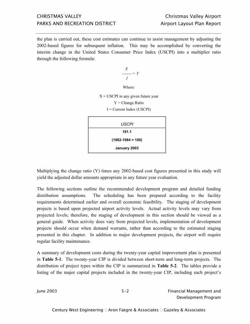
CHRISTMAS VALLEY Christmas Valley Airport PARKS AND RECREATION DISTRICT Airport Layout Plan Report
June 2003 5-2 Financial Management and Development Program
Century West Engineering Aron Faegre & Associates Gazeley & Associates
the plan is carried out, these cost estimates can continue to assist management by adjusting the 2002-based figures for subsequent inflation. This may be accomplished by converting the interim change in the United States Consumer Price Index (USCPI) into a multiplier ratio through the following formula:
X ------- = Y
I
Where:
X = USCPI in any given future year Y = Change Ratio
I = Current Index (USCPI)
USCPI
181.1
(1982-1984 = 100)
January 2003
Multiplying the change ratio (Y) times any 2002-based cost figures presented in this study will yield the adjusted dollar amounts appropriate in any future year evaluation.
The following sections outline the recommended development program and detailed funding distribution assumptions. The scheduling has been prepared according to the facility requirements determined earlier and overall economic feasibility. The staging of development projects is based upon projected airport activity levels. Actual activity levels may vary from projected levels; therefore, the staging of development in this section should be viewed as a general guide. When activity does vary from projected levels, implementation of development projects should occur when demand warrants, rather than according to the estimated staging presented in this chapter. In addition to major development projects, the airport will require regular facility maintenance.
A summary of development costs during the twenty-year capital improvement plan is presented in Table 5-1. The twenty-year CIP is divided between short-term and long-term projects. The distribution of project types within the CIP is summarized in Table 5-2. The tables provide a listing of the major capital projects included in the twenty-year CIP, including each project’s

CHRISTMAS VALLEY Christmas Valley Airport PARKS AND RECREATION DISTRICT Airport Layout Plan Report
June 2003 5-3 Financial Management and Development Program
Century West Engineering Aron Faegre & Associates Gazeley & Associates
eligibility for FAA funding. The FAA will not participate in vehicle parking, hangar development, building renovations, utilities, or costs associated with non-aviation developments.
The short-term phase of the capital improvement program includes the highest priority projects recommended during the first five years. Long-term projects are expected to occur beyond the next five years, although changes in demand or other conditions could accelerate or slow demand for some improvements. As with most airports, pavement related improvements represent the largest portion of CIP needs at Christmas Valley during the current planning period:
• Preserve/Resurface Existing Airfield Pavement 60% • New or Reconstructed Airfield Pavement 23% • NAVAIDS, Lighting, Marking 6% • Other Items (Fencing, Access Roads, etc.) 11%
Total 100%
Short Term Projects
Short-term projects at Christmas Valley include pavement maintenance on the runway and the apron. The construction of the north side parallel taxiway is identified as the highest priority (and most costly) new development project. Other short-term projects include the addition of lighted wind socks at both ends of the runway. Property acquisition for the Runway 7 RPZ is also listed, although no specific dollar value is identified at this time due to the multiple parcels and differing levels of development involved. A property appraisal will be required to establish potential FAA funding levels.
Long Term Projects
Long-term projects include Precision Approach Path Indicators (PAPI) on both runway ends, hangar taxilane construction, and two phases of airport fencing. Property acquisition is identified in the long-term period for the off-airport aircraft apron. Airfield pavement maintenance projects are repeated throughout the long-term planning period. Resurfacing projects for the runway and aircraft apron are also identified as long-term projects.

CHRISTMAS VALLEY Christmas Valley Airport PARKS AND RECREATION DISTRICT Airport Layout Plan Report
June 2003 5-4 Financial Management and Development Program
Century West Engineering Aron Faegre & Associates Gazeley & Associates
TABLE 5-1 20-YEAR CAPITAL IMPROVEMENT PROGRAM
2003 TO 2022
Project Qty. Unit Unit $ Total Cost* FAA Eligible Local
Short Term Projects (Years 1 - 5) Slurry Seal Runway and East Holding Area (2003) 36,800 SY $3.60 $132,480 $119,232 $13,248 Slurry Seal Apron (2003) 11,667 SY $3.60 $42,001 $37,801 $4,200 Construct East Parallel Taxiway w/ 2 Mid Field Exits (5,200 x 25') 14,175 SY $30 $430,250 $387,225 $43,025 Parallel Taxiway Edge Reflectors 5,200 LF $3 $15,600 $14,040 $1,560 Lighted Wind Socks (Both Ends of Rwy) 2 ea $7,500 $15,000 $13,500 $1,500 Property Acquisition (West RPZ) 1.6 acres $0 $0 $0 $0
Total Short Term Projects $635,331 $571,798 $63,533
Long Term Projects (Years 6 - 20) Precision Approach Path Indicators (PAPI) 2 ea $35,000 $70,000 $63,000 $7,000 Construct Hangar Taxilane (300 x 20') 667 LF $30 $25,010 $22,509 $2,501
Airport Fencing Phase I (Terminal Area; Northwest Section of Airport) w/ vehicle & ped. gates 1,400 LF $15 $23,500 $21,150 $2,350 Apron/Hangar Flood Lighting 4 ea $6,000 $24,000 $21,600 $2,400 Slurry Seal Runway and East Holding Area (2009) 36,800 SY $3.60 $132,480 $119,232 $13,248 Slurry Seal Apron (2009) 11,667 SY $3.60 $42,001 $37,801 $4,200 Airport Fencing Phase II (North and South Sides of Airfield) 13,300 LF $15 $199,500 $179,550 $19,950 Property Acquistion (west apron) 0.50 acres $0 $0 $0 $0 Slurry Seal Runway & Parallel Taxiway (2015) 51,000 SY $3.60 $183,600 $165,240 $18,360 Resurface Apron (Asphalt Overlay) 11,667 SY $12.00 $140,004 $126,004 $14,000 Resurface Runway (Asphalt Overlay) 36,800 SY $12.00 $441,600 $397,440 $44,160 Slurry Seal Parallel Taxiway (2021) 14,175 SY $3.60 $51,030 $45,927 $5,103 Slurry Seal Apron (2021) 11,667 SY $3.60 $42,001 $37,801 $4,200
Total Long Term Projects $1,374,726 $1,237,254 $137,473
TOTAL SHORT & LONG TERM PROJECTS $2,010,058 $1,809,052 $201,006
* Project costs include 30% engineering and contingency.

CHRISTMAS VALLEY Christmas Valley Airport PARKS AND RECREATION DISTRICT Airport Layout Plan Report
June 2003 5-5 Financial Management and Development Program
Century West Engineering Aron Faegre & Associates Gazeley & Associates
TABLE 5-2 CIP PROJECTS BY CATEGORY
Project Qty. Unit Unit $ Total Cost* FAA Eligible Local / State
Short Term Projects Preserve/Resurface Existing Pavement Slurry Seal Runway and East Holding Area (2003) 36,800 SY $3.60 $132,480 $119,232 $13,248 Slurry Seal Apron (2003) 11,667 SY $3.60 $42,001 $37,801 $4,200 Subtotal $174,481 $157,033 $17,448 New or Reconstructed Pavement Construct East Parallel Taxiway w/ 2 Mid Field Exits (5,200 x 25') 14,175 SY $30 $430,250 $387,225 $43,025 Subtotal $430,250 $387,225 $43,025 NAVAIDS, Lighting, Marking Parallel Taxiway Edge Reflectors 5,200 LF $3 $15,600 $14,040 $1,560 Lighted Wind Socks (Both Ends of Rwy) 2 ea $7,500 $15,000 $13,500 $1,500 Subtotal $30,600 $27,540 $3,060 OTHER ITEMS Property Acquisition (West RPZ) 1.6 acres $0 $0 $0 $0 Subtotal $0 $0 $0 Total Short Term Projects $635,331 $571,798 $63,533
Long Term Projects Preserve/Resurface Existing Pavement Slurry Seal Runway and East Holding Area (2009) 36,800 SY $3.60 $132,480 $119,232 $13,248 Slurry Seal Apron (2009) 11,667 SY $3.60 $42,001 $37,801 $4,200 Slurry Seal Runway & Parallel Taxiway (2015) 51,000 SY $3.60 $183,600 $165,240 $18,360 Resurface Apron (Asphalt Overlay) 11,667 SY $12.00 $140,004 $126,004 $14,000 Resurface Runway (Asphalt Overlay) 36,800 SY $12.00 $441,600 $397,440 $44,160 Slurry Seal Parallel Taxiway (2021) 14,175 SY $3.60 $51,030 $45,927 $5,103 Slurry Seal Apron (2021) 11,667 SY $3.60 $42,001 $37,801 $4,200 Subtotal $1,032,716 $929,445 $103,272 New or Reconstructed Pavement Construct Hangar Taxilane (300 x 20') 667 LF $30 $25,010 $22,509 $2,501 Subtotal $25,010 $22,509 $2,501
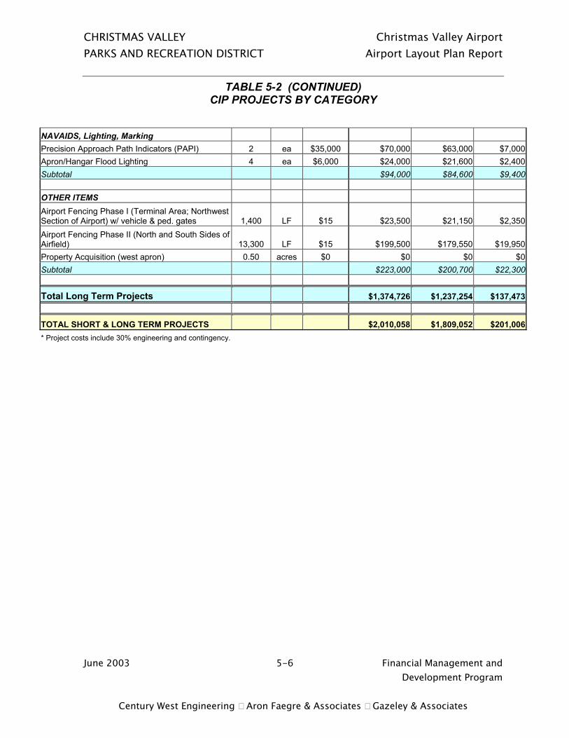
CHRISTMAS VALLEY Christmas Valley Airport PARKS AND RECREATION DISTRICT Airport Layout Plan Report
June 2003 5-6 Financial Management and Development Program
Century West Engineering Aron Faegre & Associates Gazeley & Associates
TABLE 5-2 (CONTINUED) CIP PROJECTS BY CATEGORY
NAVAIDS, Lighting, Marking Precision Approach Path Indicators (PAPI) 2 ea $35,000 $70,000 $63,000 $7,000 Apron/Hangar Flood Lighting 4 ea $6,000 $24,000 $21,600 $2,400 Subtotal $94,000 $84,600 $9,400 OTHER ITEMS Airport Fencing Phase I (Terminal Area; Northwest Section of Airport) w/ vehicle & ped. gates 1,400 LF $15 $23,500 $21,150 $2,350 Airport Fencing Phase II (North and South Sides of Airfield) 13,300 LF $15 $199,500 $179,550 $19,950 Property Acquisition (west apron) 0.50 acres $0 $0 $0 $0 Subtotal $223,000 $200,700 $22,300
Total Long Term Projects $1,374,726 $1,237,254 $137,473
TOTAL SHORT & LONG TERM PROJECTS $2,010,058 $1,809,052 $201,006 * Project costs include 30% engineering and contingency.

CHRISTMAS VALLEY Christmas Valley Airport PARKS AND RECREATION DISTRICT Airport Layout Plan Report
June 2003 5-7 Financial Management and Development Program
Century West Engineering Aron Faegre & Associates Gazeley & Associates
FINANCING OF DEVELOPMENT PROGRAM
Federal Grants
A primary source of potential funding identified in this plan is the Federal Airport Improvement Program (AIP). As proposed, approximately 90 percent of the airport’s 20-year CIP will be eligible for federal funding. Funds from this program are derived from the Aviation Trust Fund, which is the depository for all federal aviation taxes collected on such items as airline tickets, aviation fuel, lubricants, tires, aircraft registrations, and other aviation-related fees. These funds are distributed under appropriations set by Congress to all airports in the United States that have certified eligibility. The funds are distributed through grants administered by the Federal Aviation Administration (FAA).
Under current guidelines, the airport sponsor receives 90 percent participation on eligible projects. According to FAA guidelines, Christmas Valley Airport is eligible under the Airport Improvement Program (AIP) to receive discretionary grants and general aviation entitlement grants. Under the current authorization, airports like Christmas Valley receive up to $150,000 per year in the GA entitlement grants. The future availability of the GA non-primary entitlement funding is unknown and dependent on congressional reauthorization. However, based on current legislation, these grants have become a very significant source of FAA funding for general aviation airports.
The constraints of AIP funding availability will dictate in large part, the actual schedule for completing airport improvement projects through the planning period. As a result, some projects included in the twenty-year CIP may be deferred beyond the twenty-year time frame. However, federal grants are expected to continue playing a significant role in the financing of the airport's projected capital expenditures.
State Funding
The Oregon Department of Aviation (ODA) manages a pavement maintenance funding program to enable regularly-scheduled investment in airfield pavements. The program funds pavement maintenance and associated improvements (crack filling, repair, sealcoats, etc.), which have not traditionally been eligible for FAA funding. ODA also provides limited funding assistance through its Financial Assistance to Municipalities (FAM) grant program.

CHRISTMAS VALLEY Christmas Valley Airport PARKS AND RECREATION DISTRICT Airport Layout Plan Report
June 2003 5-8 Financial Management and Development Program
Century West Engineering Aron Faegre & Associates Gazeley & Associates
Financing the Local Share of Capital Improvements
For most smaller airports, one of the most challenging aspects of financial planning is generating enough revenue to match available state or federal grants for large projects. As noted earlier, FAA AIP grants usually represent the single largest source of funding for major capital projects. However, the local match level for AIP grants is set at 10 percent. As currently defined, the local match required for projects included in the current planning period is estimated to be more than $200,000 (over the next twenty years).
With the recent availability of the General Aviation Airport Entitlement Program, Christmas Valley Airport could be eligible to receive up to $150,000 per year in FAA development funds, which would require an annual local match of approximately $15,000. Although the full funding may not be required every year or within the typical three-year funding cycles, it would be advisable for the airport to base its financial planning on the ability to provide adequate matching funds to address all projected facility needs during the current planning period.
Given the limited ability to generate substantial airport revenues on an annual basis, it may be necessary to use local user assessments to fund major projects. For example, the cost of a project such as the parallel taxiway will require upwards of $50,000 in local matching funds. It may be possible to charge the equivalent of a one-time hook-up fee for airport users that will regularly use the taxiway in exchange for granting or maintaining taxiway access to the airfield. Although the parallel taxiway project is identified by local airport users as the airport’s current number one development priority, the ability to generate local funding may determine when the project can be constructed.
It is evident that the current revenue generated through existing access agreements and other airport-sourced activities will not be adequate to fund the local share of the projected capital improvements. Additional revenue generation or reallocation of other available district resources may be needed to meet all of the projected airport needs. It may also be worth considering an increased level of financial and management involvement from Lake County in the long term operation and maintenance needs of the airport.

CHRISTMAS VALLEY Christmas Valley Airport PARKS AND RECREATION DISTRICT Airport Layout Plan Report
June 2003 6-1 Environmental Checklist Century West Engineering Aron Faegre & Associates Gazeley & Associates
CHAPTER SIX ENVIRONMENTAL CHECKLIST
INTRODUCTION
The purpose of the Environmental Checklist is to identify physical, social and environmental conditions of record, which may affect the ability to undertake future improvements at Christmas Valley Airport. In comparison to an Environmental Assessment, the project scope for this review is limited and focuses on gathering and summarizing information of record from the applicable local, State and Federal sources, pertaining to existing conditions as they apply to the subject site and its environs. The scope of the review research does not involve extensive professional interpretation of the information; in-depth analyses; detailed descriptions of preferred development alternatives and their potential impacts; or the more comprehensive, follow-up correspondence and inquiries with affected agencies and persons as are normally associated with Environmental Assessments (EA). As each federally funded projects is undertaken, the FAA will evaluate the need for more detailed environmental analyses on a case bay case basis.
All research activities for this report, including correspondence, data collection and documentation, proceeded under the provisions of FAA Order 5050.4A, The Airport Environmental Handbook, which is intended to implement the requirements of Sections 1505.1 and 1507.3 of the National Environmental Policy Act (NEPA). This report briefly addresses, either in narrative or in the attached checklist format, each potential impact category identified by Order 5050.4A as to be investigated under the Environmental Impact Statement (EIS) or EA processes. If, however, a particular potential environmental impact category does not appear to apply to this study site, the checklist is noted accordingly, and little or no discussion regarding such particular topic(s) will appear in this narrative section of the report.
The Christmas Valley Airport is located in the unincorporated rural community of Christmas Valley, in northern Lake County, Oregon, approximately 13 miles northeast of Silver Lake. The subject property abuts on Christmas Valley / Wagontire Road on its northerly exterior. Surrounding uses are primarily rural residential, open space, and some limited commercial uses associated with the small community of Christmas Valley.
CHRISTMAS VALLEY Christmas Valley Airport PARKS AND RECREATION DISTRICT Airport Layout Plan Report
June 2003 6-2 Environmental Checklist Century West Engineering Aron Faegre & Associates Gazeley & Associates
Lake County has planning and zoning jurisdiction over this area, and County planning personnel indicate that the airport is zoned “Public Facilities”. Airport development and related activities are permitted outright in this zone as “public facilities and services, (including)…minor betterments thereof…” It is unclear from the information available as of this writing whether there is an identified threshold in Lake County for classifying an action as a major betterment as opposed to a minor betterment, or what the implications of any alternate policies or regulations which may apply might mean for development options at the subject facility. Zoning on surrounding lands is primarily Rural Residential (RR).
Oregon Revised Statutes (ORS) Chapter 836.600 through 836.630 addresses the appropriate zoning of Oregon’s airports and aviation-affected areas through placing certain safety restrictions upon the use and development of adjacent and neighboring properties. Among its provisions, it requires height restrictive zoning and, to some extent, use-restrictive zoning, as necessary components affecting neighboring lands around an airport’s periphery. While the Lake County zoning code includes an “Airport Approach Combining (A-A) Zone”, and in fact FAA Transitional and Horizontal Zones are indicated on the south side of the runway on the zoning graphics provided to the consultant by the local planner, this is not sufficient for demonstrating compliance with FAA regulations and / or ORS Ch. 836.600 et. seq. In addition to ensuring quality and cohesive mapping of the areas affected by the Lake County Airport Approach Combining, or Overlay, Zone, the existing zoning ordinance and transportation plan language, as applicable, should be reviewed and amended to ensure compliance with ORS Chapter 836.600-630. Among the provisions of this statute are the following (not intended to be a comprehensive summation of this legislation):
OAR 660-13-160(1) Requires jurisdictions to update Plan, land use regulations at Periodic Review to conform with provisions of this statute, or at next update of Transportation System Plan, per OAR 660-12-0015(4) and OAR 660-12-0045(2)(c)&(d). If more than one local government is affected by the Airport Safety Overlay (see below), a Coordinated Work Program for all jurisdictions is required, concurrent with timing of Periodic Review (or TSP update) for the jurisdiction having the most land area devoted to the airport use(s). The Lake County, Oregon Comprehensive Plan, Zoning Ordinance, and mapping should be amended no later than the next Periodic Review work cycle to ensure compliance with these provisions. No other jurisdictions are affected by the recommended Airport Safety Overlay Zone.
(8) Adopt map delineating Safety Zones, compatibility zones, and existing noise impact boundaries identified by OAR 340-35. See also OAR 660-13-0070(1) and Exhibits 1 & 2 to Division 13. The limited mapping which appears to be available is not adequate, as discussed above. This Airport Layout Plan Update Report will provide the information necessary to incorporate into the County zoning data and mapping files, consistent with these provisions.
CHRISTMAS VALLEY Christmas Valley Airport PARKS AND RECREATION DISTRICT Airport Layout Plan Report
June 2003 6-3 Environmental Checklist Century West Engineering Aron Faegre & Associates Gazeley & Associates
OAR 660-13-0070(2):Review future development in Airport Safety Overlay for compliance with maximum height limitations. The Airport Approach Combining Zone language provided by the Lake County planner includes some use and height limitations in airspace surfaces as defined by the FAA; however, many of these ordinances are outdated, and the definitions of the surfaces may have changed in the interim. In addition, the Safety and Compatibility zones and noise impact boundaries required by ORS 836 and OAR 660-13 are not a part of the current documents, and must be applied to the existing overlay zone ordinance. In addition, the associated mapping must be produced and adopted by Lake County.
In addition to Airport Hazard Overlay requirements described above, OAR 660-13-0040(1)-(3) also require that jurisdictions adopt a map of existing and planned airport improvements.
Consistent with the Airport Land Use Compatibility Guidelines for small general aviation airports, from the State of Oregon Department of Aviation, a 1,300-foot wide “Airport Development Area” is typically recommended to be established, centered on the runway centerline, for a length of 5,400 feet. This Airport Development Area should be “...under the airport’s control to prevent incompatible land use development.” (Page 56 of State Guidelines). This does not appear to be a feasible option to the north or south, where public roadways are located within a few hundred feet of the runway. Residential uses at the easterly end of the runway, and residential and commercial uses off the westerly end, make it unlikely that this could be realized at this time in those general directions.
The consultant recommends that a more detailed review of all applicable ordinances, Comprehensive and Transportation Plan language, and mapping pertaining to the Christmas Valley Airport be performed, to compare those with the requirements of ORS Chapter 836.600-630 for airport compatibility. This analysis would identify any amendments to the Lake County codes, plans and maps which may be necessary in order to demonstrate compliance. It is further recommended that this Airport Layout Plan Report be adopted as part of the Transportation Element of the County’s Comprehensive Plan.
NOISE EVALUATION – INTRODUCTION
Noise is sometimes defined as unwanted sound. However, sound is measurable, whereas noise is subjective. The relationship between measurable sound and human irritation is the key to understanding aircraft noise impact. A rating scale has been devised to relate sound to the sensitivity of the human ear. The A-weighted decibel scale (dBA) is measured on a “log” scale, by which is meant that for each increase in sound energy level by a factor of 10, there is a designated increase of 1 dBA. This system of measurement is used because the human ear
CHRISTMAS VALLEY Christmas Valley Airport PARKS AND RECREATION DISTRICT Airport Layout Plan Report
June 2003 6-4 Environmental Checklist Century West Engineering Aron Faegre & Associates Gazeley & Associates
functions over such an enormous range of sound energy impacts. At a psychological level, there is a rule of thumb that the human ear often “hears” an increase of 10 decibels as equivalent to a “doubling” of sound. The challenge to evaluating noise impact lies in determining what amount and what kind of sound constitutes noise. The vast majority of people exposed to aircraft noise are not in danger of direct physical harm. However, much research on the effects of noise has led to several generally accepted conclusions:
• The effects of sound are cumulative, therefore, the duration of exposure must be included in any evaluation of noise.
• Noise can interfere with outdoor activities and other communication.
• Noise can disturb sleep, TV/radio listening, and relaxation.
• When community noise levels have reached sufficient intensity, community wide objection to the noise will likely occur.
Research has also found that individual responses to noise are difficult to predict8. Some people are annoyed by perceptible noise events, while others show little concern over the most disruptive events. However, it is possible to predict the responses of large groups of people – i.e. communities. Consequently, community response, not individual response, has emerged as the prime index of aircraft noise measurement.
DNL Methodology
On the basis of the findings described above, a methodology has been devised to relate measurable sound from a variety of sources to community response. It has been termed "Day-Night Average Sound Level" (DNL) and has been adopted by the U. S. Environmental Protection Agency (EPA), the Department of Housing and Urban Development (HUD), and the Federal Aviation Administration (FAA) for use in evaluating noise impacts. In a general sense, it is the yearly average of aircraft-created noise for a specific location (i.e., runway), but includes a calculation penalty for each night flight.
The basic unit in the computation of DNL is the sound exposure level (SEL). An SEL is computed by mathematically summing the dBA level for each second during which a noise event occurs. For example, the noise level of an aircraft might be recorded as it approaches, passes overhead, and then departs. The recorded noise level of each second of the noise event is then 8 Beranek, Leo, Noise and Vibration Control, McGraw-Hill, 1971, pages ix-x.
CHRISTMAS VALLEY Christmas Valley Airport PARKS AND RECREATION DISTRICT Airport Layout Plan Report
June 2003 6-5 Environmental Checklist Century West Engineering Aron Faegre & Associates Gazeley & Associates
added logarithmically to compute the SEL. To provide a penalty for night time flights (considered to be between 10 PM and 7 AM), 10 dBA is added to each night-time dBA measurement, second by second. Due to the mathematics of logarithms, this calculation penalty is equivalent to 10 day flights for each night flight9.
A DNL level is approximately equal to the average dBA level during a 24-hour period with a weighing for nighttime noise events. The main advantage of DNL is that it provides a common measure for a variety of different noise environments. The same DNL level can describe an area with very few high noise events as well as an area with many low level events.
Noise Modeling and Contour Criteria
DNL levels are typically depicted as contours. Contours are an interpolation of noise levels drawn to connect all points of a constant level, which are derived from information processed by the FAA-approved computer noise model. They appear similar to topographical contours and are superimposed on a map of the airport and its surrounding area. It is this map of noise levels drawn about an airport, which is used to predict community response to the noise from aircraft using that airport. DNL mapping is best used for comparative purposes, rather than for providing absolute values. That is, valid comparisons can be made between scenarios as long as consistent assumptions and basic data are used for all calculations. It should be noted that a line drawn on a map by a computer does not imply that a particular noise condition exists on one side of the line and not on the other. These calculations can only be used for comparing average noise impacts, not precisely defining them relative to a specific location at a specific time.
The noise contours depicted in Figure 6-1 are plotted in 5 DNL increments starting at 55 DNL based on the 2004 forecast activity levels. Due to the minor increase in forecast air traffic anticipated during the planning period, the 2004 contours provide a reasonable indication of both existing and long-term noise exposure within the community.
Due to the narrow configuration of the airport, portions of the 55 DNL contour extend beyond airport property both to the north and south. The 60 and 65 DNL are contained within the airport boundaries along the runway. No noise sensitive land uses are located within the 60 or 65 DNL contour, although a limited number of residences are located within the 55 DNL contour.
9 Where Leq (“Equivalent Sound Level”) is the same measure as DNL without the night penalty incorporated, this can be shown through the mathematical relationship of: Leqd = 10 log ( Nd x 10 (SEL/10) ) Leqn = 10 log ( Nn x 10 ((SEL+10)/10) ) 86,400 86,400 If SEL equals the same measured sound exposure level for each computation, and if Nd = 10 daytime flights, and Nn = 1 night-time flight, then use of a calculator shows that for any SEL value inserted, Leqd = Leqn.
CHRISTMAS VALLEY Christmas Valley Airport PARKS AND RECREATION DISTRICT Airport Layout Plan Report
June 2003 6-6 Environmental Checklist Century West Engineering Aron Faegre & Associates Gazeley & Associates
Noise and Land-Use Compatibility Criteria
Federal regulatory agencies of government have adopted standards and suggested guidelines relating DNL to compatible land uses. Most of the noise and land-use compatibility guidelines strongly support the concept that significant annoyance from aircraft noise levels does not occur outside a 65 DNL noise contour. Federal agencies supporting this concept include the Environmental Protection Agency, Department of Housing and Urban Development, and the Federal Aviation Administration.
Part 150, Airport Noise Compatibility Planning, of the Federal Aviation Regulations, provides guidance for land-use compatibility around airports. Table 6-1 presents these guidelines. Compatibility or non-compatibility of land use is determined by comparing the noise contours with existing and potential land uses. All types of land uses are compatible in areas below 65 DNL. Generally, residential and some public uses are not compatible within the 65-70 DNL, and above. As noted in Table 6-1, some degree of noise level reduction (NLR) from outdoor to indoor environments may be required for specific land uses located within higher-level noise contours. Land uses such as commercial, manufacturing, some recreational uses, and agriculture are compatible within 65-70 DNL contours.

CHRISTMAS VALLEY Christmas Valley Airport PARKS AND RECREATION DISTRICT Airport Layout Plan Report
June 2003 6-7 Environmental Checklist Century West Engineering Aron Faegre & Associates Gazeley & Associates
TABLE 6-1 LAND-USE COMPATIBILITY WITH DNL
Yearly Day-Night Average Sound Level (DNL) In Decibels
_______________________________________________ Land Use Below Over _______________________________ 65 65-70 70-75 75-80 80-85 85
Residential Residential, other than mobile homes & transient lodgings............................................... Y N(1) N(1) N N N Mobile Home Parks............................................... Y N N N N N Transient Lodgings................................................ Y N(1) N(1) N(1) N N
Public Use Schools ................................................................. Y N(1) N(1) N N N Hospitals and Nursing Homes............................... Y 25 30 N N N Churches, Auditoriums, and Concert Halls .......... Y 25 30 N N N Governmental Services......................................... Y Y 25 30 N N Transportation ....................................................... Y Y Y(2) Y(3) Y(4) Y(4) Parking.................................................................. Y Y Y(2) Y(3) Y(4) N
Commercial Use Offices, Business and Professional....................... Y Y 25 30 N N Wholesale and Retail—Building Materials, Hardware and Farm Equipment ............................................................. Y Y Y(2) Y(3) Y(4) N Retail Trade--General ........................................... Y Y 25 30 N N Utilities .................................................................. Y Y Y(2) Y(3) Y(4) N Communication ..................................................... Y Y 25 30 N N
Manufacturing and Production Manufacturing General.......................................... Y Y Y(2) Y(3) Y(4) N Photographic and Optical ...................................... Y Y 25 30 N N Agriculture (except livestock) and Forestry................................................................. Y Y(6) Y(7) Y(8) Y(8) Y(8) Livestock Farming and Breeding........................... Y Y(6) Y(7) N N N Mining and Fishing, Resource Production and Extraction ....................................................... Y Y Y Y Y Y
Recreational Outdoor Sports Arenas, Spectator Sports.................................................................... Y Y(5) Y(5) N N N Outdoor Music Shells, Amphitheaters ................... Y N N N N N Nature Exhibits and Zoos...................................... Y Y N N N N Amusements, Parks, Resorts and Camps ............ Y Y Y N N N Golf Courses, Riding Stables and Water Recreation .................................................. Y Y 25 30 N N
Y (Yes) Land-use and related structures compatible without restrictions. N (No) Land-use and related structures are not compatible and should be prohibited. NLR Noise Level Reduction (outdoor to indoor) to be achieved through incorporation of noise
attenuation into design and construction of the structure. 25, 30 or 35 Land uses and structures generally compatible; measures to achieve NLR or 25, 30, or
35 dB must be incorporated into design and construction of the structure.

CHRISTMAS VALLEY Christmas Valley Airport PARKS AND RECREATION DISTRICT Airport Layout Plan Report
June 2003 6-8 Environmental Checklist Century West Engineering Aron Faegre & Associates Gazeley & Associates
NOTES:
1. Where the community determines that residential uses must be allowed, measures to achieve outdoor to indoor Noise Levels Reduction (NLR) of at least 25dB and 30dB should be incorporated into building codes and be considered in individual approvals. Normal residential construction can be expected to provide a NLR of 20 dB; thus, the reduction requirements are often stated as 5, 10, or 15 dB over standard construction and normally assume mechanical ventilation and closed windows year-round. However, the use of NLR criteria will not eliminate outdoor noise problems.
2. Measures to achieve NLR of 25 dB must be incorporated into the design and construction of portions of these buildings where the public is received, office areas, noise sensitive areas, or where the normal noise level is low.
3. Measures to achieve NLR of 30 dB must be incorporated into the design and construction of portions of these buildings where the public is received, office areas, noise sensitive areas, or where the normal noise level is low.
4. Measures to achieve NLR of 35 dB must be incorporated into the design and construction of portions of these buildings where the public is received office areas, noise sensitive areas, or where the normal noise level is low.
5. Land-use compatible, provided special sound reinforcement systems are installed.
6. Residential buildings require an NLR of 25.
7. Residential buildings require an NLR of 30.
8. Residential buildings not permitted.
SOURCE: Federal Aviation Regulations, Part 150, Airport Noise Compatibility Planning, dated January 18, 1985.
CHRISTMAS VALLEY Christmas Valley Airport PARKS AND RECREATION DISTRICT Airport Layout Plan Report
June 2003 6-9 Environmental Checklist Century West Engineering Aron Faegre & Associates Gazeley & Associates
Figure 6-1: Noise Contours

CHRISTMAS VALLEY Christmas Valley Airport PARKS AND RECREATION DISTRICT Airport Layout Plan Report
June 2003 6-10 Environmental Checklist Century West Engineering Aron Faegre & Associates Gazeley & Associates
FURTHER ENVIRONMENTAL CONSIDERATIONS
The land use and development review and overlay zoning recommended in this plan will provide a higher degree of protection from potentially incompatible land uses.
Social and induced socio-economic impacts of any improvement project at this facility would be expected to be positive. Implementation of the preferred alternative will result in the creation of temporary construction employment and improvements to the safety and viability of the airport facility. A viable airport facility serving a community generally provides increased opportunities for diversifying the local economy; responding to transportation needs of the area’s commerce; and enhancing non-commercial travel options for local citizens with access to aircraft. In addition, the Preferred Alternative will enhance the ability of the Christmas Valley Airport to continue to serve functions for “Air Life”, an aircraft-based medical emergency response program. Government and private business entities also make regular use of the facility.
Air quality is not expected to be adversely impacted as a result of plan-recommended improvements. A representative of the Oregon Department of Environmental Quality stated that the area is “in attainment for” (meaning ‘in compliance with’) applicable air quality standards. No significant increase over existing levels of air and/or surface traffic is anticipated under the Preferred Alternative.
Water quality impacts are always a concern with any construction project, and especially when considering uses and sites where potentially hazardous materials, such as aviation fuel, fire retardants, and/or agricultural chemicals are involved. No aerial applicators of agricultural chemicals are currently based at Christmas Valley Airport. The Oregon Department of Environmental Quality routinely recommends for airport projects that, at a minimum, investigations be performed which document past agricultural spraying practices, aviation fuel storage facilities, and other potential sources for adverse water quality impacts associated with past, present and potential future activities at the site. Agricultural chemical operators and airport sponsors must ensure that wash down, collection, treatment and storage devices comply with Oregon Administrative Rule 340-109 and all applicable environmental standards. This includes, but is not limited to, obtaining and complying with a National Discharge Elimination System (NPDES) Permit for all airport construction projects and ongoing operations.
During construction, adherence to the applicable local, state, and federal regulations and standards, and compliance with the guidelines of FAA Advisory Circular 150/5370-10, would help to protect against adverse water quality impacts. In the case of this particular site, DEQ’s Eastern Oregon Region Water Quality Division representative, Mr. Dick Nichols, expressed in

CHRISTMAS VALLEY Christmas Valley Airport PARKS AND RECREATION DISTRICT Airport Layout Plan Report
June 2003 6-11 Environmental Checklist Century West Engineering Aron Faegre & Associates Gazeley & Associates
telephone communication with the consultant that his office has no specific concerns regarding existing water quality conditions in this location relative to the potential projects.
The Oregon State Historic Preservation Office, SHPO, has indicated that, as of April 15, 2001, considerable documentation is required to be provided by any party inquiring about the existence of any significant cultural resources. The new procedure requires such information as architectural classification, window and roof types of all structures within the study area, if they may be considered as a resource; dates of any alterations; and “Significance Statements” for all types of resources. SHPO has specific forms, “Section 106 (of the National Historic Preservation Act) Documentation Forms” and “Section 106 Level of Effect Forms” for use in making such a request. This level of investigation surpasses the scope of this ALP Update Report. It is therefore unknown at this time whether cultural resources are recorded in the immediate area proposed for development or in the airport’s vicinity.
If any historic or cultural resources are discovered during construction, the sponsor will be responsible for immediately notifying SHPO and the other appropriate authorities. Any such resource(s) discovered would be required to be protected from adverse impacts or damages resultant from activities associated with the improvements to the Christmas Valley Airport.
Under the Department of Transportation Act, Section 4(f), (49 USC, Subtitle I, Section 303), any projects which would require use of lands having historic significance on a national, state or local level must be prior demonstrated to be the only feasible and prudent alternative and must be planned to minimize harm resulting from the use. This is not expected to be a factor in recommended acquisition of adjacent property.
According to attached correspondence from Oregon Department of Fish and Wildlife District Biologist Craig L. Foster, his department has “no data that would indicate…significant biotic resources in the vicinity of the Christmas Valley Airport.” He notes that his department has surveyed for the past several years populations of breeding birds on a route which passes the airport along the county road, Wagontire / Christmas Valley Road. This flyway may represent a potential hazard to aviation, and this potential should be considered to the extent feasible in planning take off, landing and flight patterns for the facility.
A search of the database of the Oregon Natural Heritage Program, Nature Conservancy, revealed one noteworthy species of fauna as occurring in the project vicinity. The Western burrowing owl, or Athene cunicula hypugaea, is listed as a “Species of Concern” by the US Department of Interior’s Fish and Wildlife Service (USFWS), and is considered “Sensitive-Critical” by the State of Oregon. Two adults and two juveniles were reported approximately two miles south of the community of Christmas Valley in 1994.

CHRISTMAS VALLEY Christmas Valley Airport PARKS AND RECREATION DISTRICT Airport Layout Plan Report
June 2003 6-12 Environmental Checklist Century West Engineering Aron Faegre & Associates Gazeley & Associates
The U.S. Fish and Wildlife Service (USFWS) lists one species of bird which is listed as Threatened, and which is found in the vicinity of the Christmas Valley Airport. The Bald Eagle, Haliaeetus leucocephalus, is listed as a Threatened Species. In addition, eight (8) species of mammals, ranging from the Pygmy rabbit; Pale western big-eared bat, Corynorhinus townsendii pallenscens, the Preble’s shrew, Sorex peblei, and five additional species of bats, are indicated in the USFWS’ database as “Species of Concern”.
Six birds are also Species of Concern, including the Western burrowing owl, mentioned above; Ferruginous hawk, Buteo regalis; Greater sage-grouse, Centrocercus urophasianus; Willow flycatcher, Emidonax trailli adastus; Yellow –breasted chat, Icteria virens, and Lewis’ woodpecker, Melanerpes lewis. One fish, the Interior redband trout, or Oncrhynchus mykiss gibbsi, is also a Species of Concern noted as occurring in the general vicinity of Christmas Valley, though it would not be affected by the project.
Five species of fauna, which may be found in the project’s general vicinity, are considered by the USFWS as Species of Concern. These include: Cusick’s eriogonum, Eriogonum cusickii; Prostrate wild buckwheat, Eriogonum prociduum; Disappearing monkey flower, Mimulus evanescens; Playa phacelia, Phacelia inundata; and Profuse-flowered mesa mint, or Pogogyne floribunda.
The USFWS states in the attached correspondence that a Biological Assessment is required for “construction projects (or other undertakings having similar physical impacts) which are major Federal actions significantly affecting the quality of the human environment as defined in the National Environmental Policy Act (NEPA) (42 U.S.C. 4332 (2) (c)). For projects other than major construction activities,” the USFWS’ correspondence continues, “the Service suggests that a biological evaluation similar to the Biological Assessment be prepared to determine whether they may affect listed and proposed species.”
According to a review of the US Fish and Wildlife Service’s National Wetlands Inventory (NWI), the nearest wetlands are located approximately ¾ of a mile to the south of the airport, and no inventoried wetland resources appear to be present within or in proximity to areas planned for airport related development.
According to the local planners, no flood plain areas are known to be located on or near the airport. This portion of Lake County is not mapped by either the Federal Emergency Management Agency (FEMA, the government agency responsible for mapping flood plains) or by the USDA’s Natural Resources Conservation Service Soils Surveys. No impact is anticipated under this category.

CHRISTMAS VALLEY Christmas Valley Airport PARKS AND RECREATION DISTRICT Airport Layout Plan Report
June 2003 6-13 Environmental Checklist Century West Engineering Aron Faegre & Associates Gazeley & Associates
Airport Layout Plans and associated projects are exempt from the Farmland Protection Policy Act (FPPA), and no further investigation under this impact category is necessary to demonstrate compliance with NEPA.
Silt fences, runoff diversion tactics, and stormwater detention are commonly implemented in similar projects, and should be utilized for any project on the airport in order to minimize adverse impacts of construction. FAA Advisory Circular 150/5370-10 provides additional measures, which should be implemented to minimize adverse impacts of airport construction activities. Please see the above discussion regarding water quality impacts.

CHRISTMAS VALLEY Christmas Valley Airport PARKS AND RECREATION DISTRICT Airport Layout Plan Report
June 2003 6-14 Environmental Checklist Century West Engineering Aron Faegre & Associates Gazeley & Associates
Potential Impact Category
TABLE 6-2 CHRISTMAS VALLEY AIRPORT ENVIRONMENTAL CHECKLIST
Existing Conditions / Comments
Further Action Anticipated?
Noise Adjacent airport-related residential areas located in 55DNL contours.
No
Compatible Land Use
Obstructions to airspace should be removed/lighted. Local governments must adopt and map Airport Overlay Zoning, planned improvements, ensuring consistency of zoning provisions with State law. Future uses in the vicinity must have the burden of demonstrating compatibility with aviation and compliance with ORS Ch. 836.600-630.
YES
Social / Socio-Economic
Expected to be positive, as is typical with airport projects, including but not limited to the enhancement of safety features at the airfield, creation of jobs, fencing, and improvement to the region’s transportation systems base.
YES
Air Quality Area is in attainment for air quality; no change in current conditions is anticipated.
NO
Water Quality DEQ Eastern Region Water Quality Division requires that the location of disposal for domestic wastewater (sewage) from the airports facilities be divulged, and surface storm water runoff must be contained, treated, prior to discharge to any natural drainage system, water body. NPDES Permit; silt fences, maintaining the maximum physical separation between construction and sensitive waterways, and adherence to FAA Advisory Circular 150/5370-10 required. See Construction Impacts, below. If fuel or agricultural chemical storage are to be established at this site, see Water Quality section of the above narrative and observe compliance with DEQ requirements.
POSSIBLE
Special Land Uses, DOT Act Section4(f)
No parks, recreation areas, or refuge areas per this section affected. State Government owns some land which may be desired for aviation uses. Further analysis advised.
POSSIBLE
Historic, Architectural, Archaeological, and Cultural Resources
Records no longer provided by SHPO. Please see above discussion. Avoid impacting known or suspected resources, notify SHPO immediately if new resources located during construction.
POSSIBLE

CHRISTMAS VALLEY Christmas Valley Airport PARKS AND RECREATION DISTRICT Airport Layout Plan Report
June 2003 6-15 Environmental Checklist Century West Engineering Aron Faegre & Associates Gazeley & Associates
Potential Impact Category
TABLE 6-2 CHRISTMAS VALLEY AIRPORT ENVIRONMENTAL CHECKLIST
Existing Conditions / Comments
Further Action Anticipated?
Biotic Communities One species of fauna was discussed in the narrative above as possibly occurring in the project vicinity. No impact anticipated under this category.
NO
Endangered and Threatened Species
One Threatened Species, several Species of Concern identified as occurring in vicinity. A Biological Evaluation or Assessment is recommended by USFWS prior to construction or similar undertakings. See narrative.
YES
Wetlands According to National Wetlands Inventory Maps produced by the USFWS, no wetland resources affected by the project.
NO
Floodplain No mapping available from Federal Emergency Management Agency (FEMA). No flood plain suspected by local planning officials.
NO
Shoreline Management
Not Applicable to this facility. NO
Coastal Barriers Also Not Applicable. NO
Wild and Scenic Rivers
Not Applicable. NO
Farmland Soils on airport property are not mapped by the NRCS. Moreover, public airport improvement projects on private lands are exempt from Farmland Protection Policy Act (FPPA). It cannot be determined, from the information currently available, whether soils on the site, which are under Federal ownership, qualify for protection under the FPPA. Further coordination with either local planning officials or the Department of Land Conservation and Development is necessary to answer this question.
POSSIBLE
Energy Supply and Natural Resources
No adverse impacts anticipated. NO
Light Emissions and Glare
No analysis of existing light emissions, which might pose potential hazards to aviation, performed. No such hazards reported by local planners or operators, upon inquiry.
POSSIBLE

CHRISTMAS VALLEY Christmas Valley Airport PARKS AND RECREATION DISTRICT Airport Layout Plan Report
June 2003 6-16 Environmental Checklist Century West Engineering Aron Faegre & Associates Gazeley & Associates
Potential Impact Category
TABLE 6-2 CHRISTMAS VALLEY AIRPORT ENVIRONMENTAL CHECKLIST
Existing Conditions / Comments
Further Action Anticipated?
Solid Waste Impacts Ground and surface water systems must be considered and protected from contamination during the handling of waste materials. Development under the Preferred Alternative would not considerably increase production of waste at the facility, except during construction phase.
NO
Construction Impacts
Temporary impacts will accrue during construction phase. Adherence to the provisions of FAA Advisory Circular 150/5370-10 should preclude foreseeable adverse impacts.
NO