Christine J. Alvarado - Design Rationale
104
A Natural Sketching Environment: Bringing the Computer into Early Stages of Mechanical Design by Christine J. Alvarado Submitted to the Department of Electrical Engineering and Computer Science in partial fulfillment of the requirements for the degree of Master of Science in Computer Science and Engineering at the MASSACHUSETTS INSTITUTE OF TECHNOLOGY May 2000 c Massachusetts Institute of Technology 2000. All rights reserved. Author .............................................................. Department of Electrical Engineering and Computer Science May 5, 2000 Certified by .......................................................... Randall Davis Professor of Computer Science and Engineering Thesis Supervisor Accepted by ......................................................... Arthur C. Smith Chairman, Departmental Committee on Graduate Students
Transcript of Christine J. Alvarado - Design Rationale

A Natural Sketching Environment: Bringing the
Computer into Early Stages of Mechanical Design
by
Christine J. Alvarado
Submitted to the Department of Electrical Engineering and ComputerScience
in partial fulfillment of the requirements for the degree of
Master of Science in Computer Science and Engineering
at the
MASSACHUSETTS INSTITUTE OF TECHNOLOGY
May 2000
c© Massachusetts Institute of Technology 2000. All rights reserved.
Author . . . . . . . . . . . . . . . . . . . . . . . . . . . . . . . . . . . . . . . . . . . . . . . . . . . . . . . . . . . . . .Department of Electrical Engineering and Computer Science
May 5, 2000
Certified by. . . . . . . . . . . . . . . . . . . . . . . . . . . . . . . . . . . . . . . . . . . . . . . . . . . . . . . . . .Randall Davis
Professor of Computer Science and EngineeringThesis Supervisor
Accepted by . . . . . . . . . . . . . . . . . . . . . . . . . . . . . . . . . . . . . . . . . . . . . . . . . . . . . . . . .Arthur C. Smith
Chairman, Departmental Committee on Graduate Students

A Natural Sketching Environment: Bringing the Computer
into Early Stages of Mechanical Design
by
Christine J. Alvarado
Submitted to the Department of Electrical Engineering and Computer Scienceon May 5, 2000, in partial fulfillment of the
requirements for the degree ofMaster of Science in Computer Science and Engineering
Abstract
Current computer-based design tools for mechanical engineers are not tailored to earlystages of design. Most designers use pencil and paper at first, and input their designinto CAD systems only after it is nearly complete. The tradeoff between the easeof drawing and the precision of a CAD tool is too great for engineers who are justsketching out rough designs. This thesis presents a tool that is specifically gearedtoward the earlier stages of design. Our system interprets and represents sketchesas the user sketches them, then allows the user to simulate her system using a two-dimensional kinematic simulator. This thesis introduces a method for translatinga sketch into the designer’s intended mechanical devices, despite ambiguities in thesketch.
Thesis Supervisor: Randall DavisTitle: Professor of Computer Science and Engineering

Acknowledgments
I would like to thank my advisor Randy Davis for helpful discussions, ideas, and
guidance throughout the duration of this work.
I would like to thank Luke Weisman and Mike Oltmans for many hours of discus-
sion and collaboration on this work. Luke helped get my work off the ground, and
Mike helped me continue through it.
I would like to thank all the members of the AI Lab and the Laboratory for
Computer Science who participated in the user studies. Their feedback was invaluable
to the evaluation and future direction of this work.
I would like to thank the National Science Foundation and the Ford Motor Com-
pany for their financial support.
Finally, I want to thank my friends and family for their encouragement, especially
Mark Foltz who willingly provided me with feedback, assistance and support whenever
I needed it.

4

Contents
1 Introduction 15
1.1 A Design Tool Worth Using . . . . . . . . . . . . . . . . . . . . . . . 15
1.2 The Importance of a Sketch . . . . . . . . . . . . . . . . . . . . . . . 17
1.3 The Benefits of a Computer in Early Design . . . . . . . . . . . . . . 18
1.3.1 An Interface to Existing Tools . . . . . . . . . . . . . . . . . . 18
1.3.2 Design Rationale Capture . . . . . . . . . . . . . . . . . . . . 19
1.3.3 Simulation in Early Design . . . . . . . . . . . . . . . . . . . . 20
1.4 Challenges in Sketch Interpretation and Display . . . . . . . . . . . . 20
1.4.1 Pattern Recognition . . . . . . . . . . . . . . . . . . . . . . . 21
1.4.2 Ambiguity . . . . . . . . . . . . . . . . . . . . . . . . . . . . . 21
1.4.3 Display . . . . . . . . . . . . . . . . . . . . . . . . . . . . . . 22
1.4.4 Misinterpretation . . . . . . . . . . . . . . . . . . . . . . . . . 22
1.5 Contributions Toward a Natural Interface . . . . . . . . . . . . . . . 22
1.5.1 Overview of the Solution . . . . . . . . . . . . . . . . . . . . . 23
1.6 Structure of this Thesis . . . . . . . . . . . . . . . . . . . . . . . . . . 26
2 Creating a Natural Drawing Environment 29
2.1 How a Person Draws on Paper . . . . . . . . . . . . . . . . . . . . . . 30
2.2 Interpreting a Sketch . . . . . . . . . . . . . . . . . . . . . . . . . . . 31
2.2.1 Levels of Interpretation . . . . . . . . . . . . . . . . . . . . . . 31
2.2.2 Ambiguities in the Drawing . . . . . . . . . . . . . . . . . . . 33
2.2.3 How the Observer Recognizes the Sketch . . . . . . . . . . . . 34
2.3 Interaction with the User . . . . . . . . . . . . . . . . . . . . . . . . . 37
5

2.3.1 Expressing Confusion . . . . . . . . . . . . . . . . . . . . . . . 37
2.3.2 Aggressive vs. Passive Recognition . . . . . . . . . . . . . . . 38
3 The Problem of Recognition 41
3.1 Sketch Recognition vs. Language Recognition . . . . . . . . . . . . . 42
3.2 Combining Multiple Sources of Evidence . . . . . . . . . . . . . . . . 43
3.2.1 Pattern Matching . . . . . . . . . . . . . . . . . . . . . . . . . 43
3.2.2 Temporal Evidence . . . . . . . . . . . . . . . . . . . . . . . . 44
3.2.3 Simpler is Better . . . . . . . . . . . . . . . . . . . . . . . . . 44
3.2.4 Specificity Rules . . . . . . . . . . . . . . . . . . . . . . . . . 45
3.2.5 User Feedback . . . . . . . . . . . . . . . . . . . . . . . . . . . 45
4 The Sketching Interface 49
4.1 The Original Recognition System . . . . . . . . . . . . . . . . . . . . 49
4.1.1 RecSystem’s Interface . . . . . . . . . . . . . . . . . . . . . . 50
4.1.2 Recognition in RecSystem . . . . . . . . . . . . . . . . . . . . 50
4.1.3 Limitations to RecSystem . . . . . . . . . . . . . . . . . . . . 51
4.2 A Shrewd Sketch Interpretation and Simulation Tool: ASSIST . . . . 52
4.2.1 An Example . . . . . . . . . . . . . . . . . . . . . . . . . . . . 53
4.2.2 The Power of Simulation . . . . . . . . . . . . . . . . . . . . . 56
4.2.3 The Part Library . . . . . . . . . . . . . . . . . . . . . . . . . 58
4.3 Managing Multiple Interpretations . . . . . . . . . . . . . . . . . . . 60
4.3.1 Avoiding User Confusion . . . . . . . . . . . . . . . . . . . . . 61
4.3.2 Pruning the Number of Interpretations . . . . . . . . . . . . . 62
4.4 Correcting Interpretation Errors . . . . . . . . . . . . . . . . . . . . . 63
4.5 Level of Aggressiveness . . . . . . . . . . . . . . . . . . . . . . . . . . 64
4.5.1 The Advantages of Aggressive Recognition . . . . . . . . . . . 64
4.5.2 The Disadvantages of Aggressive Recognition . . . . . . . . . 65
5 The Underlying Structure of ASSIST 67
5.1 The Structure of RecSystem . . . . . . . . . . . . . . . . . . . . . . . 67
6

5.1.1 The Basic Model . . . . . . . . . . . . . . . . . . . . . . . . . 67
5.1.2 The Recognition Process . . . . . . . . . . . . . . . . . . . . . 69
5.2 ASSIST: Overview . . . . . . . . . . . . . . . . . . . . . . . . . . . . 70
5.3 Widget Pools . . . . . . . . . . . . . . . . . . . . . . . . . . . . . . . 70
5.4 Recognition . . . . . . . . . . . . . . . . . . . . . . . . . . . . . . . . 71
5.5 Reasoning . . . . . . . . . . . . . . . . . . . . . . . . . . . . . . . . . 71
5.5.1 Reasoning Heuristics . . . . . . . . . . . . . . . . . . . . . . . 73
5.5.2 Ranking the Interpretations . . . . . . . . . . . . . . . . . . . 75
5.6 Resolution . . . . . . . . . . . . . . . . . . . . . . . . . . . . . . . . . 79
6 User Studies 83
6.1 Procedure . . . . . . . . . . . . . . . . . . . . . . . . . . . . . . . . . 83
6.1.1 Test Examples . . . . . . . . . . . . . . . . . . . . . . . . . . 85
6.2 Results . . . . . . . . . . . . . . . . . . . . . . . . . . . . . . . . . . . 86
6.2.1 Drawing Style . . . . . . . . . . . . . . . . . . . . . . . . . . . 87
6.2.2 Stroke Interpretation . . . . . . . . . . . . . . . . . . . . . . . 88
6.2.3 Visual Feedback . . . . . . . . . . . . . . . . . . . . . . . . . . 90
6.2.4 ASSIST as More Than Paper . . . . . . . . . . . . . . . . . . 91
6.3 Summary of Study Results . . . . . . . . . . . . . . . . . . . . . . . . 92
7 Related Work 93
8 Future Work 95
8.1 Low Level Recognizers . . . . . . . . . . . . . . . . . . . . . . . . . . 95
8.2 Sketching Using the Computer as a Tool . . . . . . . . . . . . . . . . 96
8.3 Learning and Adaptation . . . . . . . . . . . . . . . . . . . . . . . . . 97
8.4 Adding Intelligent Behavior . . . . . . . . . . . . . . . . . . . . . . . 97
9 Conclusion 101
7

8

List of Figures
1-1 The user draws the sketch of the circuit breaker (left). When she clicks
the run button, she sees a simulation of her sketch (right). . . . . . . 16
1-2 The top portion of the circuit breaker depicted in Figure 1-1 as the
user drew it (left), and displayed by the system (right). . . . . . . . . 23
1-3 The user selects the bottom portion of the sketch. . . . . . . . . . . . 24
1-4 The user deletes the selected items by drawing a line through them. . 25
1-5 The remaining items in the sketch, after the deletion. . . . . . . . . . 26
1-6 To simulate the sketch, the user taps the run button. . . . . . . . . . 27
1-7 The first three lines of a square, displayed by ASSIST. . . . . . . . . 27
1-8 An overview of the recognition algorithm used by ASSIST. . . . . . . 28
1-9 A square body, displayed by ASSIST. . . . . . . . . . . . . . . . . . . 28
2-1 A simple illustration of sketching order. Consider the simple system in
part (a). Part (b) labels a reasonable version of the order in which the
first 10 strokes of the system were drawn. In contrast, part (c) shows
a stroke ordering we would probably never observe. . . . . . . . . . . 31
2-2 A typical menu-based interface. The user is constrained to select from
among the menu items displayed. . . . . . . . . . . . . . . . . . . . . 32
2-3 An example of ambiguity in the drawing. The bold strokes in (b) and
(c) are identical to the strokes in (a). When (a) is drawn, an observer
cannot know whether the device will become a ball and socket as in
(b), or a set of gears, as in (c). . . . . . . . . . . . . . . . . . . . . . . 33
2-4 A block with a pin joint in the upper right corner. . . . . . . . . . . . 36
9

3-1 Two rectangular bodies. People use different stroke order when draw-
ing the bodies. . . . . . . . . . . . . . . . . . . . . . . . . . . . . . . 44
3-2 The user draws a spring (left). The system interprets the stroke as
both a spring (center) and as a series of lines or rods (right). . . . . . 45
3-3 A polygonal body, displayed by ASSIST (a). When the user draws
the line in (b), it would be surprising if the system displayed the in-
terpretation in (c) because the user has already seen the body as a
whole. . . . . . . . . . . . . . . . . . . . . . . . . . . . . . . . . . . . 46
4-1 Two examples of how one might draw a square. . . . . . . . . . . . . 51
4-2 A reproduction of Figure 2-3. The strokes in (a) become part of a ball
and socket (b) or a set of gears (c). . . . . . . . . . . . . . . . . . . . 52
4-3 A car on a hill, as drawn in ASSIST. . . . . . . . . . . . . . . . . . . 53
4-4 The simulation of a car rolling down a hill. . . . . . . . . . . . . . . . 54
4-5 The user selects the wheel and joint for editing. . . . . . . . . . . . . 55
4-6 The user moved the wheel to the left. . . . . . . . . . . . . . . . . . . 56
4-7 The user tries to draw a wheel. . . . . . . . . . . . . . . . . . . . . . 57
4-8 The system misinterprets the user’s stroke as a pin joint. . . . . . . . 58
4-9 The Try Again dialog box. . . . . . . . . . . . . . . . . . . . . . . . . 59
4-10 An ambiguous system. Depending on the length of the spring, the
spring constant, and the strength of the force, the system will behave
differently . . . . . . . . . . . . . . . . . . . . . . . . . . . . . . . . . 59
4-11 Two equally valid interpretations for the five strokes on the left. . . . 60
4-12 The user selects the bottom portion of the sketch. (Reprint of Figure 1-3) 62
5-1 The user completes a quadrilateral. . . . . . . . . . . . . . . . . . . . 68
5-2 A simple recognition graph for a square. The parents are higher in
the figure, and the lines connect parents and children. Each of the
user’s raw strokes are recognized as lines. Then the lines together
are recognized as a quadrilateral, the quadrilateral is recognized as a
rectangle and the rectangle is recognized as a square. . . . . . . . . . 72
10

5-3 The interpretation ordering algorithm. The edges in the graph are
labeled with the number of the rule that created them. The relative
scores assigned to the interpretations are shown above the nodes at the
bottom. . . . . . . . . . . . . . . . . . . . . . . . . . . . . . . . . . . 76
5-4 Two results from topological sort on an interpretation graph. The
results are combined to form the graph on the bottom. . . . . . . . . 77
5-5 A recognition graph for four strokes. . . . . . . . . . . . . . . . . . . 80
5-6 A recognition graph for four strokes with scores. . . . . . . . . . . . . 81
6-1 The two warmup examples. . . . . . . . . . . . . . . . . . . . . . . . 84
6-2 A scale. . . . . . . . . . . . . . . . . . . . . . . . . . . . . . . . . . . 85
6-3 A Rube-Goldberg machine. . . . . . . . . . . . . . . . . . . . . . . . . 86
6-4 A circuit breaker. . . . . . . . . . . . . . . . . . . . . . . . . . . . . . 87
6-5 The system fails to recognize the two crossed strokes as an anchor in
the recognition step. . . . . . . . . . . . . . . . . . . . . . . . . . . . 89
8-1 An example used in describing annotations. . . . . . . . . . . . . . . 98
11

12

List of Tables
5.1 Recognizers in a simple environment. . . . . . . . . . . . . . . . . . . 68
5.2 An illustration of the RecSystem recognition process. The item in bold
is the interpretation that includes the last stroke the user drew. . . . 68
6.1 Questions we asked the subjects. . . . . . . . . . . . . . . . . . . . . 85
13

14

Chapter 1
Introduction
1.1 A Design Tool Worth Using
Engineers first sketch their designs using pencil and paper. Only after their design
is relatively stable do they take the time to input their system into computer aided
drafting (CAD) tools. The reason for the delayed use of CAD tools is simple: com-
puters are too difficult to use for the payoff that they provide at this stage. Consider
writing a report using a computer. For the trained typist, typing is no more diffi-
cult than writing (some would say that it is simpler and faster), and the computer
provides a world of payoffs for the writing of the document: clean representation,
ability to edit without having to rewrite the whole report, spell checking, and so on.
But while computers are especially good at representing and working with textual
input, they are rather bad at working with drawings. There are freehand drawing
programs that allow the designer to edit and save her drawings, but these benefits
are not compelling enough to persuade the user to abandon pencil and paper.
This thesis takes one step toward creating a tool powerful and natural enough
to be used from the beginning stages of mechanical design. Our long term vision is
a system that would allow the engineer to draw as freely as she draws with a pen
and paper, but that would watch her as she drew, understanding her sketch as she
worked. At any time she wanted, the engineer would be able to stop drawing and
simulate the system as it was drawn to get a feel for how all the parts of the system
15

worked together. Along the way the computer would monitor her design decisions
and ask her to explain parts of the system that might be confusing or design decisions
that might not be obvious to another engineer. Finally, when she was done with her
drawing and satisfied with her design, she would press a button, and the computer
would automatically input the major pieces of her design into the CAD tool of her
choice. She would only have to fix minor details that were not obvious in her drawing.
The computer system would have all the knowledge of another designer and would
not need constant help to work with the engineer’s sketch.
We took a first step toward accomplishing this vision by creating a program called
ASSIST (A Shrewd Sketch Interpretation and Simulation Tool) that understands a
user’s sketch while she draws. To build this system we had to answer several questions:
What should the system do if it does not know what the user is drawing? How should
it indicate its confusion? When should it choose an interpretation and when should
it just let the user draw? Answering these and other questions was fundamental to
building a sketch system that allows the user to express herself as freely as she does
when sketching with pencil and paper.
Our system provides a natural and powerful environment for mechanical engineer-
ing sketches. The user can draw naturally while the system interprets and represents
her strokes as a mechanical system. At any time in the drawing process, the user
can see a simulation of her design by tapping the run button. Figure 1-1 shows a
Figure 1-1: The user draws the sketch of the circuit breaker (left). When she clicksthe run button, she sees a simulation of her sketch (right).
16

session in which the user has drawn a circuit breaker in ASSIST (left) and sees the
simulation (right). During the drawing process she did not have to explicitly identify
any of the parts in her system; as she sketched, ASSIST recognized the pieces of her
sketch by their form and context. She also did not have to enter her system into
the simulator; when she tapped the run button, the system automatically input her
design into two-dimensional mechanical simulator.
1.2 The Importance of a Sketch
Sketching is an important component in early design. Almost all mechanical designers
begin their designs by sketching their ideas out before moving to the computer for
two reasons: engineers often want to express their ideas quickly and naturally, and
sketches give them a rough visual representation of how their system will look. The
indispensable nature of sketching throughout the design process is what motivates
the development of a tool that helps designers sketch on the computer instead of just
on paper.
Engineers make several drawings in the course of the design process, ranging from
informal sketches to formal drafting. Drawing is not just an artifact of the design
process, in fact, it has been shown to be essential at all stages of the design process
(Ullman et al., 1990). In the early stages of design, engineers typically draw rough
sketches on paper or on a white-board. This stage of the drawing can further be
broken down into two types of marks: graphic representations such as drawings of
mechanical parts, and support notation such as textual notes and dimensions (Ullman
et al., 1990). The work presented here focuses on graphic representations made in the
first stages of mechanical design. However, we recognize the importance of including
a method to allow people to annotate their sketches as they design. Such a method
is the subject of work being pursued in (Oltmans, ).
Sketching is also useful in other design areas such as architecture or graphical
interface design. Other research has acknowledged the importance of informal sketch
recognition and it is an area of active work (Landay and Meyers, 1995; Stahovich,
17

1996; Gross, 1996). While each project’s focus is slightly different, the long term
goal of each is the same: to build a tool that supports the design process from the
earliest design stage to the manufacturing of the finished product. CAD tools have
been confined to the end stages of the design process because people are unwilling
to sacrifice the utility of sketching freely that is so important in early design. Until
recently, the only way they could get this ability was with pencil and paper.
1.3 The Benefits of a Computer in Early Design
Although paper provides a natural and uninhibiting interface, it has its limitations.
Paper allows the user to record designs, but does not allow the designer to work with
the design as a mechanical system. Also, to edit a design, the user must cross out,
erase, or redraw the part she wishes to change. A computer tool for early design
potentially has many advantages over paper: the user would not be forced express
the ideas twice by first sketching on paper and then transferring the design to the
computer, it would be easier for the user to edit the design on the computer, the
computer could record the changes made to the design as the user worked, and the
computer could simulate the user’s design as she developed it.
1.3.1 An Interface to Existing Tools
A sketch based design tool provides a more natural interface to existing CAD tools.
Menu-based CAD tools lock the user into choosing and placing parts. When the user
wants to add a spring to a piece of the drawing, she must go to the menu, choose
a spring, and then place it in her drawing, instead of just drawing a spring where
she wanted it in the first place. The menu-based interface breaks up the designer’s
thought process in a way that sketching on paper does not.
A sketch based interface would also save the user the overhead of having to enter
the design into the computer after she had sketched it on paper. If the computer
could translate the user’s sketch directly into a format that CAD tools understand,
the user would only have to input the details that were not explicit in her sketch.
18

1.3.2 Design Rationale Capture
Design rationale capture is an important topic in mechanical design. We believe that
having the ability to sketch a design on the computer would make it easier to capture
design rationale over the full course of the design.
Design rationale is useful so others can understand the finished product when
the engineer is not around to explain it. Engineers come and go, and projects often
get passed on from one person to the next. When a new designer comes to work
on a system she does not understand, she faces a large time overheard to simply
understand the original system. Moreover, not understanding what design decisions
were made, she is liable to make the same mistakes as the previous designer. Design
rationale capture is also useful to the designer herself. After several months or years
of working on the same project, a designer tends to forget why she made the decisions
she did, or how certain parts of the system work.
However, as useful as recording design rationale may be, it rarely seems worth
the effort to the designer. Engineers often design first, thinking they will return and
document later. Unfortunately, after the design is complete the designer often has
forgotten important decisions that were made during the design, or simply fails to
provide a complete record of the process. After all, design rationale is often generated
for someone else, and the designer herself has little to gain from investing the effort
to record it in detail. Thus, documentation often ends up incomplete or missing
altogether.
Bringing the computer into the early stages of the design process is a first step
toward design rationale capture because the computer would, at a minimum, be able
to record changes to the design over the full course of its development. Many of
the important decisions and changes to the design are made before the user begins
using CAD tools. With a natural sketch-based computer design tool, the designer
could work directly on the computer from the early stages of design. Although ideally
we would like to capture the reasoning behind the changes, a program that simply
recorded what changes were made to the design would be helpful to someone else
19

trying to make sense of the finished product.
1.3.3 Simulation in Early Design
Another advantage to working on the computer in early design is that the user would
be able to simulate her design at any time during its development. Currently, engi-
neers wait until the end the the design process to simulate their systems. In early
design, the designer must trust that the mechanics will work the way she thinks they
will. When a design is changing often, it is not worth the effort to enter it into a
simulation program to see how it runs. On the other hand, if the user were to sketch
directly into a system that interpreted her design, the user would be able to simulate
her sketch at any point in the design process and go right back to sketching.
1.4 Challenges in Sketch Interpretation and Dis-
play
As noted earlier, computers are used primary at the end stages of design because
they are good at formally representing mechanical devices. However, they are not
good at interpreting sketches of such devices and translating them into a format that
can be used in fabrication or simulation. CAD and simulation tools force the user to
explicitly identify each mechanical part as she adds it to her design by providing her
with fixed menus of parts from which to choose. In other words, to “draw” a gear,
the user must pick the symbol for “gear” from a table or list and then adjust the size
and placement of the part within the design.
On the other hand, a sketch based tool should be able to identify the mechanical
parts in the user’s drawing by the way she draws them and the context in which
they appear. Unfortunately, recognizing the user’s sketch is not easy; the system
must recognize patterns in the user’s sketch as mechanical parts and must be able to
resolve ambiguities in the sketch. The system also needs to express its interpretation
naturally to the user. Finally, the system needs to handle misinterpretation elegantly.
20

1.4.1 Pattern Recognition
The first challenge in building a system to understand sketches is recognizing the
meaningful patterns in the drawing. This task in itself is not trivial because each
time engineers sketch mechanical parts, they sketch them slightly differently. There-
fore, pattern matching templates must be flexible enough to allow for some variation
between sketches, but constrained enough not to accept incorrect patterns.
1.4.2 Ambiguity
In addition, a sketch is inherently ambiguous as the user is drawing; the same pattern
in the drawing could represent more than one mechanical part. For example, as the
engineer sketches each line, the computer cannot be sure if the line is a rod, a string
or part of some larger piece that is currently being drawn.
There are two steps to handling ambiguities in a sketch: detecting the ambiguities,
and resolving them. To detect ambiguities the system must be able to detect when
there could be more than one interpretation for a stroke or group of strokes in the
drawing. To resolve the ambiguities in the sketch, the program must be able to decide
at what point it has enough information to determine the correct interpretation for
a given stroke or set of strokes.
Determining the optimal level of aggressiveness in resolving ambiguities has its
tradeoffs. On the one hand, if the program is too aggressive in its interpretation, it
will annoy the user by jumping to incorrect conclusions about the interpretation of
the drawing before the user has a chance to finish her drawing. On the other hand, if
the system waits too long to decide on the interpretation and makes an interpretation
mistake, it forces the user to correct interpretations of strokes in part of the drawing
she is already finished with. The user will not want to be interrupted much later in
the drawing process to correct a mistake that was made long ago.
21

1.4.3 Display
Another issue to building a natural interface is the manner in which the program
expresses its interpretation of the drawing to the user.
Some programs leave the user’s sketch untouched but display the interpretation
for each part in a section of the screen beside the drawing surface (Gross, 1996). An
advantage of this method is that it does not change the user’s strokes in the sketch.
A disadvantage is that it forces the user to look away from her sketch to make sure
the system has the correct interpretation for her strokes.
An alternative method is to modify the user’s strokes as she draws, displaying the
system’s feedback directly on the drawing surface. This method does not force the user
to look away from the sketch to see the system’s interpretation of the drawing. But
if the system changes the user’s strokes significantly, the user may become irritated
by the changes to her sketch.
1.4.4 Misinterpretation
Handling error correction elegantly is another difficulty in creating a usable interface.
Any computer program will make mistakes in interpreting a user’s sketch, due to
ambiguities in the drawing or miscalibration of the recognition engine. Ideally, the
user should become aware of any misinterpretations quickly, and should be able to
correct them intuitively and easily; the error correction should not interrupt the
user’s train of thought. Users should always understand what has gone wrong in the
interpretation and be given a way to fix the problem quickly. If the system makes
too many errors or if the errors are too difficult to correct, the interface becomes
cumbersome, and the user will resort to designing on paper.
1.5 Contributions Toward a Natural Interface
This thesis presents the following contributions to the task of creating a natural
sketching environment:
22

• A general architecture for representing and resolving ambiguities in a sketch.
• A drawing program (ASSIST) that uses a knowledge base including knowledge
of drawing style, mechanical engineering design and visual perception to resolve
ambiguities in mechanical engineering sketches.
• A link from the drawing program to a simulation program to give designers a
way to simulate their designs as they sketch them.
• An evaluation of the program’s interface through user studies.
1.5.1 Overview of the Solution
ASSIST allows the user to draw and edit simple mechanical systems using a fixed
library of parts, then simulate them. As the user draws the system recognizes me-
chanical objects in the sketch and replaces the user’s strokes with icons that represent
the recognized part (Figure 1-2). The icons are scaled to best fit the user’s sketch and
Figure 1-2: The top portion of the circuit breaker depicted in Figure 1-1 as the userdrew it (left), and displayed by the system (right).
color coded to help the user understand the system’s interpretation for her sketch —
mechanical bodies are blue, rods are black, and all other mechanical parts are pink.
23

Editing is done through a series of gesture commands. The user does not have to
explicitly change between “edit mode” and “drawing mode”; the system is capable
of interpreting which strokes are edit strokes and which strokes are drawing strokes,
even though they are visually identical. A user can select a region of her drawing by
drawing a circle around it (Figure 1-3). Selected objects appear red. Once selected,
Figure 1-3: The user selects the bottom portion of the sketch.
the objects can be moved by dragging them with the pen or deleted by drawing a
line through them (Figures 1-4, 1-5). To simulate her design, the user taps the run
button (Figure 1-6).
ASSIST evaluates the user’s sketch after each stroke she draws, applying a three
step process to incorporate the new stroke into the drawing: recognition, reasoning,
and resolution (Figure 1-8).1 In the recognition step, ASSIST generates all possible
interpretations for the user’s last stroke by matching the most recent stroke and the
1A stroke is defined by the points traced beginning when the user puts her pen on the tablet,and ending when she lifts it up.
24

Figure 1-4: The user deletes the selected items by drawing a line through them.
strokes near it to a series of templates. In the reasoning step, the system applies
knowledge of mechanical engineering, drawing style and human object perception to
determine the most likely interpretation for the last stroke drawn. In the resolution
step, it finds the highest scored interpretation and displays that interpretation to
the user. Although only one interpretation for each stroke is shown to the user, the
system maintains other interpretations for the stroke internally.
Consider what the system does as the user draws a square. The user has drawn
three of the four lines in the square. Each side is represented as a separate line on
the canvas (Figure 1-7). When the user adds the fourth line, the system must decide
how to represent the strokes on the screen. The interpretations generated in the
recognition step are 4 lines, 4 rods, a square, or a square body.2 In the reasoning
step, the system then ranks these interpretations by assigning each interpretation a
numerical score. Then in the resolution step, the system sees that the interpretation
2A square is a geometric shape that may be used to create other mechanical parts, such as amotor. A square body is a solid body in a mechanical system
25
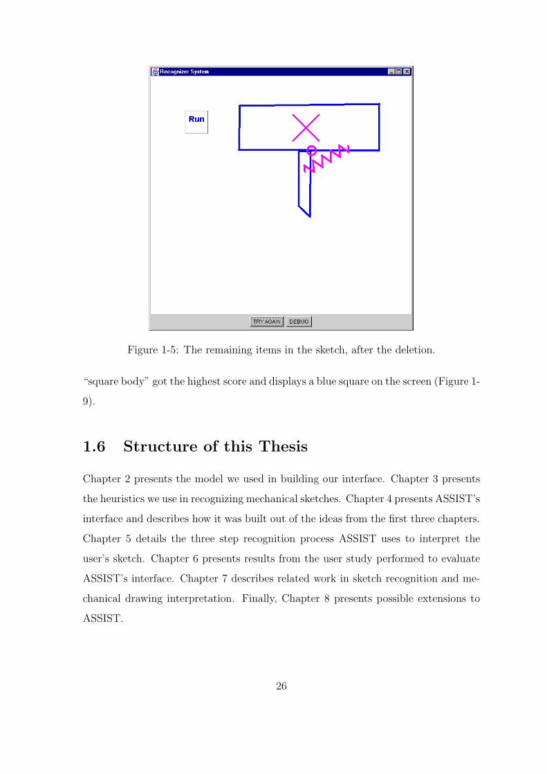
Figure 1-5: The remaining items in the sketch, after the deletion.
“square body” got the highest score and displays a blue square on the screen (Figure 1-
9).
1.6 Structure of this Thesis
Chapter 2 presents the model we used in building our interface. Chapter 3 presents
the heuristics we use in recognizing mechanical sketches. Chapter 4 presents ASSIST’s
interface and describes how it was built out of the ideas from the first three chapters.
Chapter 5 details the three step recognition process ASSIST uses to interpret the
user’s sketch. Chapter 6 presents results from the user study performed to evaluate
ASSIST’s interface. Chapter 7 describes related work in sketch recognition and me-
chanical drawing interpretation. Finally, Chapter 8 presents possible extensions to
ASSIST.
26

Figure 1-6: To simulate the sketch, the user taps the run button.
Figure 1-7: The first three lines of a square, displayed by ASSIST.
27

Recognition: Determine all possible interpretations for the stroke
Reasoning: Rank the generated interpretationsrelative to one another
Resolution: Find the highest scored set of interpretations
This shape could be...1. A square that will be used
4. A square body used for something else3. Four lines that will be 2. Four rods
in another object (e.g. a window)
I know that...
1. Four lines appearing in this formation are usually interpreted as a square2. Mechanical interpretations are preferable to abstract ones.3. All four lines were drawn consecutively
likely interpretation for the strokes is "square body"When we combine the above evidence, the most
Figure 1-8: An overview of the recognition algorithm used by ASSIST.
Figure 1-9: A square body, displayed by ASSIST.
28

Chapter 2
Creating a Natural Drawing
Environment
When people sketch with a pencil and paper, they know exactly what to expect. They
are so accustomed to pencil and paper they often do not know how to describe what
it is that makes sketching so simple and natural.
One of our main goals in developing a natural sketching system was to determine
what people expect from an interactive sketch system. Obviously, we could create
a natural environment by letting people sketch on paper and then scanning their
sketches into the computer, or even simply by recording the strokes people make as
they sketch on paper, as for example is done by the CrossPad. But this type of
sketching does not permit any sort of interaction between the system and the user.
To develop a natural interactive sketching environment we examined the task from
two angles: how do people draw on paper, and how do we get the computer system to
recognize what the person is drawing? In practice (if not in principle), any recognition
system trades off between freedom and power. A system that allows the user to draw
freely may misinterpret pieces of the drawing. On the other hand, a system that
forces the user to pre-specify every part that she is going to draw and precisely how it
will be drawn rarely makes a mistake, but constrains the user’s drawing techniques.
To find a natural balance between freedom and power we chose a real-world model
to imitate. To provide the computer with recognition power yet preserve most of
29

the freedom of drawing on paper, we examined how a person witnessing the drawing
session would understand the strokes being drawn. A computer program that behaves
as intelligently as an informed person watching the drawing process would feel natural
to the user. The more intelligent the program (and the person), the better.
With this model in mind, we considered the behavior of the designer as well as
the behavior of the observer. What does the designer expect from both the sketching
surface and the observer? What process does the observer use in order to understand
what the designer is drawing? When is it natural and acceptable for the observer to
interrupt in order to ask a question of the designer? Answering these questions will
give us a behavioral foundation upon which to base our sketch system.
2.1 How a Person Draws on Paper
To understand how to create a natural drawing environment, we first consider how
a person draws on paper. We would like to change the user’s behavior as little as
possible, so we examined what makes drawing with pencil and paper feel natural.
Paper offers its user a total freedom of expression in the sketch. When a person
draws with paper, everything she draws is represented on the page exactly as she
draws it. Drawing on paper is also unrestrained in that there are only two modes of
interaction: the user can add pigment to the page, or remove it.
Even though drawing on paper is unrestrained, there are some patterns to the way
people sketch. First, in mechanical engineering sketches people use a relatively fixed
set of icons to represent mechanical parts (Artobolevsky, 1976; Muzumdar, 1999).
Second, people tend to draw strokes in a constrained order, finishing one part of their
sketch before moving on to another part. For example, consider the different ways a
person could sketch the system in Figure 2-1. She, of course, is free to draw the lines
in any order, but in general she will not. The drawing order in part (c) seems absurd
and would likely never occur in practice.
30

1
2
3
46
7
8
9
105
10
81 7
2
5
9 6
4
3
(a)
(b) (c)
Figure 2-1: A simple illustration of sketching order. Consider the simple system inpart (a). Part (b) labels a reasonable version of the order in which the first 10 strokesof the system were drawn. In contrast, part (c) shows a stroke ordering we wouldprobably never observe.
2.2 Interpreting a Sketch
The goal of this thesis was to make the computer system behave as a human observer
does while witnessing and understanding a sketching session. In this section we
present two challenges in interpreting a sketch: level of interpretation and ambiguity
in the sketch. We then examine how a human observer deals with these challenges
when interpreting a designer’s sketch as she draws it.
2.2.1 Levels of Interpretation
When an observer witnesses a drawing session, he can have different levels of under-
standing for the strokes on the page. He might see strokes, shapes, or mechanical
objects, depending on his expectations and prior knowledge.
Naıve drawing programs such as Microsoft r©Paint are only capable of representing
31

graphics and drawings in terms of pixel representations and have no understanding
of the drawings beyond that. This level of understanding is clearly unobtrusive and
simple to implement, but also completely useless in helping the designer work with
the drawing as a mechanical system.
A helpful observer recognizes the pieces of the drawing as mechanical parts and
has a notion of how they fit together. CAD and simulation tools represent diagrams
in terms of mechanical parts, but they cannot abstract these representations from low
level sketch input. They require the user to input her system through a fixed menu
of mechanical objects (Figure 2-2). Such programs can best be viewed as observers
who can understand a mechanical system but must be told explicitly what parts are
in the system as they are added. A sketch-based program, on the other hand, should
Figure 2-2: A typical menu-based interface. The user is constrained to select fromamong the menu items displayed.
be able to interpret a sketch as a mechanical system directly, without having to be
explicitly told what is being drawn.
32

2.2.2 Ambiguities in the Drawing
Another issue in sketch interpretation is ambiguities in the drawing. When a designer
is sketching on paper, she knows exactly what she wants to draw. In other words,
she knows which strokes belong to which mechanical parts, and she knows what is
missing from the drawing. She has knowledge of what she intends to draw before
she even starts sketching. An observer, on the other hand, could become confused at
different stages of the drawing process because he does not know what the designer
will draw next.
Consider the case where the designer is drawing a ball and socket mechanism
(Figure 2-3a). She knows what the end product will look like (Figure 2-3b), so when
she draws the first part of it she does not even consider that there could be other
interpretations for the group of strokes she has drawn. However, the group of strokes
(b) (c)
(a)
Figure 2-3: An example of ambiguity in the drawing. The bold strokes in (b) and(c) are identical to the strokes in (a). When (a) is drawn, an observer cannot knowwhether the device will become a ball and socket as in (b), or a set of gears, as in (c).
could also represent the first part of an interlocking gear mechanism (Figure 2-3c). An
observer watching the designer has no way of knowing which mechanism the designer
is drawing from the strokes that are drawn. Both images begin with identical strokes
33

but diverge into conceptually distinct entities.
2.2.3 How the Observer Recognizes the Sketch
The observer’s task is to make sense of the sketch without prior knowledge as to
what is being drawn. As he watches the drawing processes, he continually makes
sense of the strokes on the page as new strokes get added. He may choose to delay
recognition of some strokes, or alternatively he may choose to make a guess as to
the interpretation of what has been drawn. If he chooses an interpretation for a
piece of the drawing that is incomplete, he expects the user to complete the drawing
according to his interpretation. For example, if an observer chooses to interpret the
drawing in Figure 2-3a as the beginning of a gear, he expects the designer to add in
the other lines attached to the circle. If the designer instead completes the drawing
as in part (b), the observer has to recognize that his first interpretation was incorrect
and replace it with the ball and socket interpretation. Although the observer has a
good idea about which parts the designer might draw, at a given point it may be
ambiguous as to which part the user is actually drawing. In this section we explore
how an observer resolves inherent ambiguities in a mechanical sketch as the designer
draws and how a computer system can resolve these same ambiguities to recognize
the mechanical parts depicted by the user’s sketch.
Fluid Interpretation
In order to understand a designer’s sketch, the observer must have a flexible and fluid
interpretation of the sketch, i.e. he must not lock himself into his first interpretation.
Imagine an observer who, at the first glance of Figure 2-3, decided that the user was
trying to draw a gear. What if this interpretation turns out to be incorrect? An
intelligent observer can detect when an interpretation guess must be rejected and a
new interpretation considered. This fluidity of interpretation is essential to produce
the correct interpretation of sketches that pass through phases of ambiguity.
A knowledgeable observer will also be able to detect when the drawing is ambigu-
34

ous. For example, the first stroke the user draws has no context, and therefore is
probably only a small piece of a larger structure. An observer has no way of knowing
what the structure is, and probably waits before trying to interpret this stroke. When
the observer detects ambiguity, he expects that any interpretation he makes could be
incorrect, and considers his interpretation tentative until he is more sure that it is
correct.
When to Commit to an Interpretation
Having a fluid or delayed interpretation of the drawing is not enough on its own. The
observer also needs to be able to detect when he has enough information to believe
his interpretation of the sketch. People are capable of deciding that they have enough
information to interpret parts of sketches, even when they are incomplete.
Deciding when there is enough recognition context is a difficult problem, especially
in the case of low-level structures. Consider the case of circular bodies. When can
the observer be sure that the user has drawn a circular body, and that the circle is
not part of a pulley that has not yet been completed? Because circles are low-level
structures, it is likely that they will soon be used to construct other mechanical parts.
But after some period of time, if a circle has not been used in a higher-level structure,
the observer can assume that the circle is not going to be used in another piece of
the drawing and can consider that circle a body.
Our system has to be more aggressive than a human in committing to interpre-
tations for pieces of the drawing because it relies on feedback from the user to help
maintain correct interpretations for each piece of the sketch. A human observer can
always wait for more information. Similarly, if the system waits for more information
it will probably have a better shot at determining the correct interpretation. Un-
fortunately, more information tends to slow our system’s recognition process. More
strokes in the sketch give rise to more interpretations to be considered and our rea-
soning engine takes a longer time to come up with an interpretation. For humans,
on the other hand, more information tends to lead to faster recognition (Biederman,
1987). One reason for this is that the brain is capable of parallel processing, and might
35
therefore process several interpretations for the image at once (Kolb and Whishaw,
1996), while ASSIST must consider each stage of the recognition and disambiguation
process sequentially. Also, there is strong psychological and biological evidence for
top down processing in the brain, that might activate certain interpretations based
on expectation (Kolb and Whishaw, 1996; Palmer, 1975; Ullman, 1996). Our system
has limited top down processing and must therefore consider each interpretation when
deciding on a representation for the sketch.
Making an Intelligent Interpretation
In order to make a correct interpretation, the observer must not only decide when to
interpret the sketch, he must have knowledge about what interpretations are preferred
over others. Simply put, to be able to interpret a drawing, a system needs to know
what it should expect. The more a system knows, the better it will be at interpreting
what the user draws. For example, it needs to know that when it sees four lines
connected to form a square, they probably represent a square body, not four rods.
There is nothing that says they have to be part of a square, but most people would
expect them to be, so an intelligent system should also.
To help our system correctly interpret ambiguous sections of the sketch, we built
in knowledge about which interpretations are preferred over others. For example, a
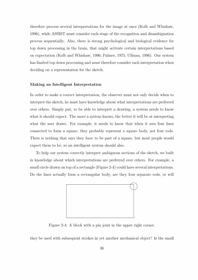
small circle drawn on top of a rectangle (Figure 2-4) could have several interpretations.
Do the lines actually form a rectangular body, are they four separate rods, or will
Figure 2-4: A block with a pin joint in the upper right corner.
they be used with subsequent strokes in yet another mechanical object? Is the small
36

circle a circular body or a pin joint?1 The most likely interpretation is that this is
a block that will be connected to another body by the pin joint in its upper right-
hand corner. The system needs knowledge of the domain in order to come to this
conclusion. The following rules apply to this simple example:
• Mechanical bodies are preferred to abstract shapes.
• Bodies are preferred over rods.
• Pin joints are preferred over circular bodies if they appear in conjunction with
a mechanical body.
These rules are only a small subset of the total body of rules the system needs to
reason about ambiguities in arbitrary mechanical drawings. Chapter 5 discusses the
knowledge we built into our system in more detail.
2.3 Interaction with the User
Another problem in building an interactive sketching system is determining how to
interact with the user. In our system, we use the display as the primary point of
interaction. The advantage to this method is that the user does not have to look
away from her sketch to receive feedback from the system. The disadvantage is that
the feedback could easily interfere with the design process.
2.3.1 Expressing Confusion
When the computer gets confused as to the interpretation of the sketch, it should ask
the designer questions. As long as it asks natural questions every once in a while, the
designer will not become too frustrated with having to answer them.
Our system keeps from getting confused by displaying its interpretation of the
sketch periodically as the user sketches. Displaying the interpretation is like asking
1A pin joint is a pivot joint linking two bodies, or one body and the background. It is depictedin our system by a small circle.
37

the implicit question, “This is what I think. Am I right?” As long as the system is
correct, the user simply continues to sketch, uninterrupted.
When the system is incorrect, or unsure as to the correct interpretation, it gives
the designer a quick, easy way to help it. First, it lets the designer know which part of
the drawing it does not understand by displaying an icon for each piece of the drawing
it has interpreted. When the system gets a wrong interpretation, it is apparent to
the user because the system displays the wrong icon for her strokes. It then tells
the designer all the interpretations it does have for her sketch by displaying the full
list of interpretations for the misinterpreted part and allowing the user to choose the
correct interpretation. The system never hides information from the designer. The
user knows immediately how to correct the system’s mistake.
2.3.2 Aggressive vs. Passive Recognition
Because the display is our feedback mechanism, another area to consider is how
aggressively the system displays its recognition. Each stroke the the user draws could
have several interpretations. As an extreme example, consider the case of each line
that the user draws. Each line could possibly be a rod. How does the system know
that the first line that the user draws is not a rod? It can’t be sure. Given the same
situation, a human observer would not be sure either. It might make sense for the
system to consider each line as a rod until it has information that causes it to believe
otherwise. However, we do not want to bother the user with this distinction at this
point. Imagine a system with an aggressive display that printed the word “rod” next
to each straight line immediately after it was drawn. This display style would not only
distract the user, but also force her to give feedback to fix the incorrect assessment
where none is necessary, because the system will fix its interpretation of the line as
soon as more information is available.
In other words, a system should not be too aggressive in its display. It should be
aware of the shapes that can be used to form more complex objects (e.g. rectangles,
lines, and circles) and hold off on interpretation until it is sure the user will not alter
that section of the sketch. A good principle is to only tentatively recognize low-level
38

structures until the user moves to a new location in the sketch. When the user moves
to a new region in the sketch, the system can then be fairly certain as to the identity
of the previous set of strokes and can employ a more aggressive interpretation and
display strategy. This notion is based on the drawing order heuristic presented in
Section 2.1. When a user moves to a new region of the drawing we assume that she
has finished a coherent, interpretable structure in the section of the drawing she left.
39

40

Chapter 3
The Problem of Recognition
Probably the most important part of creating a natural sketching interface is having
a flexible but accurate recognition engine. The fewer mistakes the system makes,
the less the user will have to pause in his work to correct the system’s mistakes. In
practice, we cannot build a system that makes no mistakes, but we strive to make as
few as possible.
Inherent ambiguities in mechanical sketches make recognition difficult. Because
we cannot be totally sure at any point that we have all the information we need to
recognize a given part of the drawing, we must be flexible in our interpretation. If
there exists more than one interpretation for a given stroke, we should keep track of
that fact.
The problem of recognition can be broken down into two major conceptual parts:
recognizing all possible interpretations, and deciding which is the most likely inter-
pretation for the given context. In this chapter, and in the thesis in general, I am
concerned primarily with the latter problem. While it is important to recognize all
possible interpretations correctly, deciding which one to display to the user is piv-
otal to creating a sketching environment that displays an understanding of the user’s
sketch. A system that always presents a plausible but not contextually relevant in-
terpretation is tedious and frustrating.
41

3.1 Sketch Recognition vs. Language Recognition
From our viewpoint, sketch recognition can be seen as a language recognition problem.
Spoken language is made up of a relatively small set of sounds, called phonemes.1
Phonemes combine in unique ways to form morphemes, that in turn form words.
Similarly, we work under the assumption that basic geometric shapes (lines, circles,
polygons, etc.) combine to form low-level pieces of mechanical drawings (such as
bodies, pin joints, gears and springs) that in turn combine to form larger systems.
The conventions for combining the low-level parts into more complex structures define
the grammar of mechanical engineering sketching.
The idea that visual image processing is done by recognizing and combining low-
level primitives is not new. Biederman argues that there are 36 visual primitives
(geons), equivalent to phonemes in speech, that make up all distinguishable visual
images (Biederman, 1987). On the neurological level, there is strong evidence that
the brain reconstructs images by extracting features rather than dealing directly with
raw patterns of light.2 Even in the retina, there are cells that respond to patterns of
light such as lines at different orientations (Kolb and Whishaw, 1996). It is widely
accepted that the visual system does a large amount of feature extraction before
images even get to the brain.
We can draw several parallels between the difficulties in building a spoken lan-
guage recognition system and the difficulties we face in building a mechanical sketch
recognition system. The most notable way in which our view of sketch recognition
parallels speech recognition is that both are primarily concerned with resolving am-
biguity. In their book on speech recognition, Jurafsky and Martin state, “most or
all tasks in speech and language processing can be viewed as resolving ambiguity”
(Jurafsky and Martin, 2000). In low-level language recognition, it is often hard to
distinguish between different phonemic sounds. In speech processing, as in sketch
recognition, knowledge of the domain is essential to resolve these ambiguities. Speech
1For example, English is made up of around 40 phonemes2For early results in this area see (Corning and Balaban, 1968).
42

recognition systems often use a dictionary and a grammar to help a computer system
resolve ambiguities at the lowest level. Our recognition system contains rules about
the mechanical parts it should expect and rules about how those mechanical parts
are likely to combine.
The process of sketch recognition is also like speech recognition in that it has a
strong temporal component. Phonemes can only combine with temporally adjacent
phonemes to form other words. It makes no sense to ask whether the third and
tenth phoneme in a signal can be part of the same word unless the fourth through
ninth are also included in the same word. Similarly, because sketches are temporally
constructed visual images, temporal data can help the system extract and combine
the visual features. Photographic images, on the other hand, convey only spatial
information; the order that the items in the scene appeared does not matter. Low-
level visual features are typically difficult to extract (see (Mahoney, 1987)) and it is
often simpler, faster and more accurate interpret high-level images such as faces or
people directly from pixel data.
3.2 Combining Multiple Sources of Evidence
Our approach to resolving ambiguity in sketches is to combine multiple sources of
evidence within the drawing. ASSIST combines pattern matching with rules about
mechanical engineering and drawing style to produce its interpretation for the sketch.
3.2.1 Pattern Matching
ASSIST recognizes elements in the user’s drawing by applying a series of pattern
matching recognizers to the sketch after each stroke the user draws. When a recog-
nizer detects the pattern it is tuned to detect, it creates an instance of that inter-
pretation. Note that the system generates several interpretations for each stroke the
user draws, so it must still choose the correct interpretation for the stroke. However,
it is important not to miss a feasible interpretation because the system cannot choose
an interpretation that is not created by the recognizers.
43

3.2.2 Temporal Evidence
The system uses temporal information in the sketch to help determine the correct
interpretation for a group of strokes. Imagine trying to decide whether or not an “X”
is an anchor.3 If the user draws the two strokes continuously, there is evidence that
it is. If, on the other hand, the user draws one stroke of the “X” first, moves to a
different part of the drawing and draws something else, and then comes back to finish
the “X”, we can conclude that the “X” is probably not an anchor.
On the other hand, we must be careful not to let temporal evidence dominate the
recognition process. In practice, we found that there are times when people actually
sketch two objects in parallel. Consider the example in Figure 3-1, which depicts a
set of blocks of equal shape and size. People sometimes drew the four horizontal lines
before drawing any of the four vertical lines. This goes against our heuristic that
Figure 3-1: Two rectangular bodies. People use different stroke order when drawingthe bodies.
people draw all of one object before moving on to another object. In this case, spatial
evidence should dominate and the system should turn the strokes into blocks instead
of leaving them as rods.
3.2.3 Simpler is Better
Another set of knowledge rules deals with the complexity of interpretations. The
fewer parts that can be fit to a set of strokes, the more likely that interpretation
is. One rule illustrating this point is the spring rule (Figure 3-2). When the user
draws the stroke on the left, in addition to recognizing the stroke as a spring (center),
the system will also try to segment the line that makes up the spring into its linear
components and interpret them as rods, or as lines that can be combined later with
3An anchor fixes a body to the background, regardless of what forces are applied to the body. Itis depicted by an “X” in ASSIST.
44

Figure 3-2: The user draws a spring (left). The system interprets the stroke as botha spring (center) and as a series of lines or rods (right).
other strokes to form other mechanical objects (right). The interpretation of the
stroke as separate lines is probably incorrect. If the system can interpret one stroke
as one part, it will because people rarely draw multiple objects with a single stroke.
3.2.4 Specificity Rules
The recognizers in the first step of the interpretation process have different scopes of
recognition—some recognize a wide range of strokes, while others apply only in a more
specific context. In the reasoning step, the system prefers interpretations produced
by recognizers with more specific domains. For example, if we know that the circle
recognizer considers all closed loops drawn with a single stroke to be circles, then we
know it will fire any time the user selects objects by drawing a circle around them.
Therefore the selection recognizer is more specific than the circle recognizer, because
only a subset of all circles are selections, but all selections are circles. In this case,
the system prefers the interpretation “selection” over the interpretation “circle.”
3.2.5 User Feedback
Finally, an important part of recognition comes from user feedback. When the system
recognizes a part incorrectly, it is up to the user to correct its interpretation. For
45

instance, suppose the user draws two crossed rods, and the system misinterprets the
rods as an anchor. The user then expresses to the system that it misinterpreted her
drawing. She informs the system of the correct interpretation, and proceeds with her
sketch. At this point, the system can be sure that the two crossed rods cannot be
an anchor, even though visually it may be feasible. We must be sure that the system
does not present the user with options she has already explicitly ruled out.
In addition, the system maintains the interpretations displayed to the user by not
choosing an interpretation that conflicts with the interpretations already displayed.
Consider a polygonal body, for example (Figure 3-3a). When the system recognizes
Figure 3-3: A polygonal body, displayed by ASSIST (a). When the user draws theline in (b), it would be surprising if the system displayed the interpretation in (c)because the user has already seen the body as a whole.
46

the body (Figure 3-3b), it displays a single object to the user. But, the sides of the
body can still be interpreted separately and when a user draws a line through the
side of the body, the system recognizes an anchor. However, because the user already
saw her strokes displayed as a polygonal body, it is surprising to see the polygon
broken apart and the anchor formed (Figure 3-3c). We avoid this sort of unexpected
interpretation in our system.
47

48

Chapter 4
The Sketching Interface
4.1 The Original Recognition System
ASSIST is built upon the work of Luke Weisman and Manoj Muzumdar. They began
work on the recognition and representation problem by building a recognition and
representation method that could be used across multiple domains (Weisman, 1999;
Muzumdar, 1999). They constructed a system, RecSystem (Recognition System),
that could recognize and represent a variety of low-level geometric shapes. It also
provided the user with a method of interacting with these shapes through gesture
commands.
On top of this basic recognition capability, they built several context-sensitive
recognition applications. One extension of the base system aided the user in design-
ing finite state machines by interpreting circles as nodes and lines as edges between
the nodes. When nodes were moved around the page, the edges followed. Another
application allowed the user to draw floor plans for a house. A third application
allowed the user to sketch mechanical parts from among a set of predetermined parts
that the system could recognize, defined in (Muzumdar, 1999). After each stroke the
user drew, the system evaluated how that stroke, together with other parts in the
sketch, could be fit together to form one of the parts in its recognition library.
49

4.1.1 RecSystem’s Interface
RecSystem functioned in the style of many graphical editing tools. The user could
both undo and redo her actions. She could also select different pieces of her drawing
and move them around. However, instead of using a menu-based system, RecSystem
used a gesture interface. To select an object, the user clicked on (or tapped) the
object she wanted to select. Then she could drag it across the screen by holding
down the mouse button and dragging (or dragging her pen across the screen) and
finish the move by letting go of the mouse button (or lifting her pen). Users could
delete objects by clicking on them twice. RecSystem also provided additional gesture
commands to copy and rotate objects.
RecSystem also allowed users to interact with it through voice commands. Simple
grammars were built to recognize commands such as “delete this”, “help” and “exit”.
The voice recognition provided the user with a more natural way to tell the computer
to perform certain tasks.
4.1.2 Recognition in RecSystem
RecSystem was designed to be a highly modular system in which it was easy for a user
to add new recognition modes. It had a straightforward algorithm for recognizing a
user’s sketch based on a series of user-defined recognizers. For example, the recogniz-
ers in a basic geometric recognition mode might include recognizers for lines, circles,
polygons, squares and ellipses. The recognizers could be defined by any algorithm
(e.g. pattern matching, neural networks, etc.), and upon recognition were required to
return an object of the type that they recognized.
RecSystem used a winner-take-all recognition strategy. When a recognizer saw a
stroke on the surface that it recognized, it picked up that part, and replaced it with a
new interpretation. Therefore, there could only be one interpretation for each stroke
the user drew.
The greedy recognition strategy used in RecSystem also meant that the ordering of
the recognizers was important. If the user drew squares such as the ones in Figure 4-1,
50

the recognizers would each have a chance to look at them and try to recognize them.
A well-defined square, such as the one on the left, would probably be recognized as
Figure 4-1: Two examples of how one might draw a square.
a square and nothing else. However, the shape on the right might either be a square
or a circle. Therefore, the ordering of these recognizers was essential. If the square
recognizer fired first, the stroke was recognized as a square. On the other hand, if the
circle recognizer fired first, the stroke was recognized as a circle, and never had the
opportunity to be recognized as a square.
4.1.3 Limitations to RecSystem
Although RecSystem did provide the ability for users to sketch simple mechanical
parts, its functionality as a natural drawing environment was limited. RecSystem
was designed primarily with simpler applications in mind. It was an excellent and
natural environment for drawing finite state machines, for example, largely because of
the symbolic nature of the drawing process. Finite state machines are highly restricted
graphically. There is a limited number of objects one draws when working with finite
state machines including nodes, edges, and labels, and hence little opportunity for
any ambiguity. With the correct ordering of recognizers, the parts of the finite state
machine can all be recognized quickly and correctly.
But RecSystem’s aggressive and permanent recognition style did not lend itself
to more complicated sketching environments. Recall the example from Figure 2-3
(shown in Figure 4-2). RecSystem’s aggressive style of recognition and replacement
did not give it the opportunity to represent both of the images in Figure 4-2. As the
51
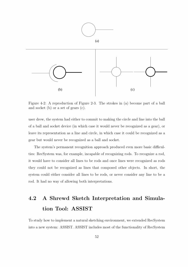
(b) (c)
(a)
Figure 4-2: A reproduction of Figure 2-3. The strokes in (a) become part of a balland socket (b) or a set of gears (c).
user drew, the system had either to commit to making the circle and line into the ball
of a ball and socket device (in which case it would never be recognized as a gear), or
leave its representation as a line and circle, in which case it could be recognized as a
gear but would never be recognized as a ball and socket.
The system’s permanent recognition approach produced even more basic difficul-
ties: RecSystem was, for example, incapable of recognizing rods. To recognize a rod,
it would have to consider all lines to be rods and once lines were recognized as rods
they could not be recognized as lines that composed other objects. In short, the
system could either consider all lines to be rods, or never consider any line to be a
rod. It had no way of allowing both interpretations.
4.2 A Shrewd Sketch Interpretation and Simula-
tion Tool: ASSIST
To study how to implement a natural sketching environment, we extended RecSystem
into a new system: ASSIST. ASSIST includes most of the functionality of RecSystem
52

and is much more flexible in its internal recognition structure.
ASSIST is an extended version of RecSystem with a mechanical engineering
sketching domain. We built the system according to the specifications for a natu-
ral drawing environment outlined in the first section of this document. It eliminates
most of RecSystem’s recognition limitations and provides the user with a natural
sketching environment, with the power to resolve ambiguity in mechanical sketches
composed of a predefined library of parts. In addition, it allows users to simulate
their designs at any time during their sketch.
4.2.1 An Example
Consider the drawing of a simple car on a hill shown in Figure 4-3. The user begins by
Figure 4-3: A car on a hill, as drawn in ASSIST.
drawing the body of the car. As the user completes the polygon, the system displays
its recognition by replacing the lines with a blue polygon. Next the user adds the
wheels of the car, which also turn blue as they are recognized as circular bodies. The
user attaches the wheels to the car with pin joints, that connect wheels to the car
and allow them to rotate. The user then draws a surface for the car to roll down, and
anchors it to the background (anything not anchored can fall). Finally, the user adds
gravity to the world by placing a force (arrow) pointing downward, not attached to
53

any object in the drawing. The user then sees his system in action by tapping on the
run button (Figure 4-4).
Figure 4-4: The simulation of a car rolling down a hill.
The first thing to note about the interaction with ASSIST is that the user drew
his whole system without interruption. The system knew enough to get the correct
interpretation in the face of ambiguities. For example, it was able to distinguish
between the wheels and the pin joints, even though visually they are both circles,
by examining the context in which the strokes appeared and applying the heuristics
outlined in Section 3.2. When the user drew the first circle, the system determined
that it was too large relative to the size of the car body to be a pin joint. When the
user drew the pin joint, the system applied its knowledge that a small circle drawn
on top of two bodies is more likely a pin joint than a body. Because the system
correctly and automatically interpreted the pieces in the user’s sketch, drawing with
the system was as easy as drawing on paper, and more natural than having to input
the same system directly into the simulation program.
ASSIST also provides a natural way for the user to make modifications to the
drawing. Say the user wants to move the wheels of the car further apart. He circles
54

the wheel and the joint and the system highlights both pieces (Figure 4-5).1 He then
Figure 4-5: The user selects the wheel and joint for editing.
drags them by putting his pen on one of the highlighted objects and dragging it to
the new position (Figure 4-6). Correcting the system’s interpretation errors is also
a simple process. Imagine that in drawing one of the wheels of the car (Figure 4-7),
the system things that the user is drawing a pin joint instead of a circular body.
The user immediately realizes the misinterpretation because his stroke turns into a
small pink circle instead of a blue circle (Figure 4-8). He can can correct the system’s
interpretation by clicking the “Try Again” button. The system presents the user
with a menu from which to choose the correct interpretation (Figure 4-9). Finally,
the system offers the user a simple way to delete parts in his system. To delete any
object or group of objects the user simply selects them by circling the objects he
wants to delete and deletes them by drawing a line through them.
Another feature to ASSIST’s interface is that it offers a quick and natural interface
to the simulator as illustrated when the user pushed the run button (Figures 4-3, 4-
4). If the user wants to test what happens when the car collides with various objects
1Note that the selection is ambiguous and could also be interpreted as a circular body. Thesystem represents the stroke as a selection because the selection recognizer is more specific than thecircular body recognizer. (See Section 3.2.4.)
55

Figure 4-6: The user moved the wheel to the left.
in the drawing he can add them into the original sketch and then hit the run button
again. He can work back and forth, adding new objects and seeing how they affect
the original mechanical system.
4.2.2 The Power of Simulation
The work presented in this thesis tackles a subset of the overall problems in creating
a complete sketching tool that can be interconnected with preexisting mechanical
design tools. To more accurately simulate the sketch we would need a description
of the sketched system’s behavior. There are behavioral ambiguities inherent in the
sketch. For example, consider the system in Figure 4-10. The drawing does not
completely constrain the behavior of the device: depending on the strength of the
force and the length and stiffness of the spring, the block may move left, move right,
or stay still. Additionally, if the block does not exactly fit against the sides of the
tube, or the force is slightly off-center, the block could twist and get jammed inside
the tube. ASSIST cannot determine the intended behavior from the sketch alone,
and displays a literal interpretation of the sketch, with default values for parameters
such as spring constants and magnitudes of forces.
Although our simulation of the user’s sketch may differ from the intended behavior,
56

Figure 4-7: The user tries to draw a wheel.
we felt that it was important to get a connection between sketch and simulation into
the system from the start. In order to provide the user with simulations of his system
at any point during the sketching process, we linked ASSIST with an off-the-shelf
simulation program called Working Model 2D by Knowledge Revolution, Inc.
Working Model has an interface typical of most design programs: it forces users to
choose from a menu of parts. The users then uses the mouse to indicate the position
and size of the part on the screen. Once the user has created a mechanical structure,
he can then see how it runs.
Conveniently for us, Working Model also allows the user to write scripts to specify
the objects and constraints in the mechanical system. ASSIST’s ability to recognize
mechanical parts and their relations enables it to create an internal representation
of these parts and relations, which it is then able to translate into Working Model’s
script language. From the user’s point of view, she has the ability to simulate her
sketch by simply clicking the run button; the result is a simulation of the sketch in
the Working Model window.
The connection between the two programs is not seamless, and has some draw-
backs. First, the simulation appears in a completely separate application. Ideally we
would like the simulation to actually control the user’s drawing, and not replicate it
57

Figure 4-8: The system misinterprets the user’s stroke as a pin joint.
elsewhere. Second, the device properties that are not obvious in the sketch (e.g. the
strength of a force, the spring constant, etc.), are set to default values in working
model. Therefore, the simulation may not behave as the user would expect.
Our motivation for linking ASSIST with the simulator was not to produce a fully
functional system, but to illustrate the direction we hope this work will follow and to
compare a sketch-based interface to a menu-based one. ASSIST’s ability to substitute
for existing interfaces to sketch programs illustrates an important property of the
system.
4.2.3 The Part Library
In order to create a useful mechanical design sketching tool, we came up with a
set of icons that are typically used in mechanical design sketches. Fortunately, the
set of icons used by mechanical engineers in sketching seems to be fairly consistent.
Muzumdar added a basic set of mechanical icons to the RecSystem (Muzumdar,
1999). We have modified this set slightly; ASSIST currently recognizes the following
mechanical parts:
• Rods
58
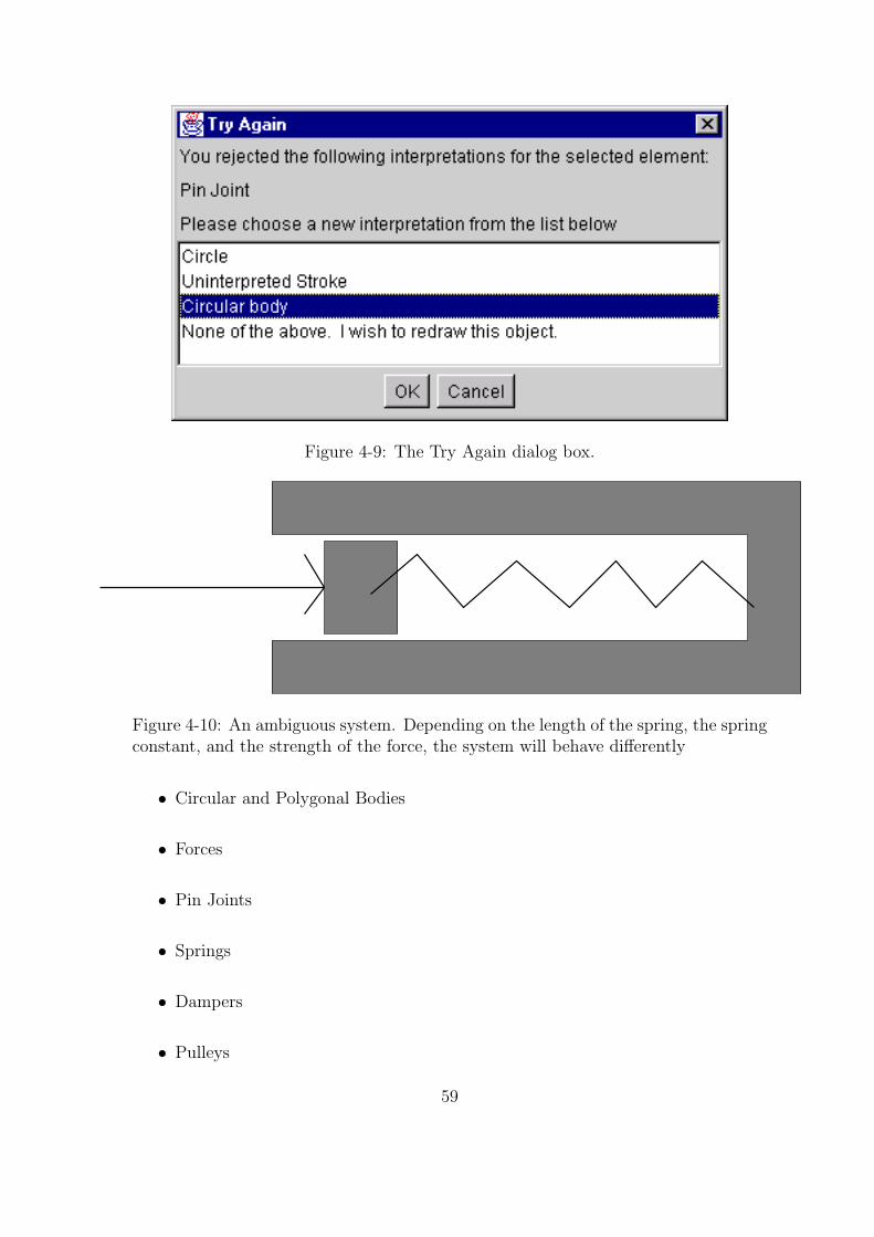
Figure 4-9: The Try Again dialog box.
Figure 4-10: An ambiguous system. Depending on the length of the spring, the springconstant, and the strength of the force, the system will behave differently
• Circular and Polygonal Bodies
• Forces
• Pin Joints
• Springs
• Dampers
• Pulleys
59

• Anchors2
4.3 Managing Multiple Interpretations
One of the greatest challenges to creating a natural sketch-based interface is inter-
preting and representing the user’s strokes as mechanical parts. Given any collection
of strokes, there could be many interpretations for the strokes. While it might be
better to leave the ambiguities uncommitted for a short period to time, we want to
eventually commit to an interpretation without always asking the user to resolve the
ambiguities. Our system is able to handle simple ambiguities (e.g. Is this stroke a
circle or a square?) as well as resolve more complicated ambiguous situations in which
the decisions made about one part can affect the decisions about other parts. For
Figure 4-11: Two equally valid interpretations for the five strokes on the left.
example, the right side of Figure 4-11 shows two interpretations for the five lines on
2An anchor is used in Working Model to fix a body to the background. It is used in ASSIST todenote any fixed body.
60
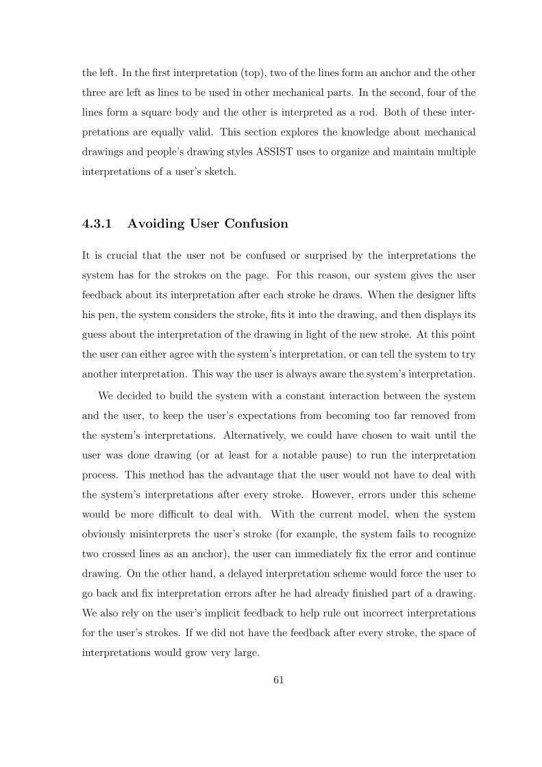
the left. In the first interpretation (top), two of the lines form an anchor and the other
three are left as lines to be used in other mechanical parts. In the second, four of the
lines form a square body and the other is interpreted as a rod. Both of these inter-
pretations are equally valid. This section explores the knowledge about mechanical
drawings and people’s drawing styles ASSIST uses to organize and maintain multiple
interpretations of a user’s sketch.
4.3.1 Avoiding User Confusion
It is crucial that the user not be confused or surprised by the interpretations the
system has for the strokes on the page. For this reason, our system gives the user
feedback about its interpretation after each stroke he draws. When the designer lifts
his pen, the system considers the stroke, fits it into the drawing, and then displays its
guess about the interpretation of the drawing in light of the new stroke. At this point
the user can either agree with the system’s interpretation, or can tell the system to try
another interpretation. This way the user is always aware the system’s interpretation.
We decided to build the system with a constant interaction between the system
and the user, to keep the user’s expectations from becoming too far removed from
the system’s interpretations. Alternatively, we could have chosen to wait until the
user was done drawing (or at least for a notable pause) to run the interpretation
process. This method has the advantage that the user would not have to deal with
the system’s interpretations after every stroke. However, errors under this scheme
would be more difficult to deal with. With the current model, when the system
obviously misinterprets the user’s stroke (for example, the system fails to recognize
two crossed lines as an anchor), the user can immediately fix the error and continue
drawing. On the other hand, a delayed interpretation scheme would force the user to
go back and fix interpretation errors after he had already finished part of a drawing.
We also rely on the user’s implicit feedback to help rule out incorrect interpretations
for the user’s strokes. If we did not have the feedback after every stroke, the space of
interpretations would grow very large.
61

4.3.2 Pruning the Number of Interpretations
Our system uses knowledge of likely and unlikely behavior to prune the space of pos-
sible interpretations. The system first rules out any interpretations that are visually
in conflict with the interpretations displayed on the screen. Imagine the user selects
several objects on the page by circling them, as in Figure 4-12. The user’s stroke
Figure 4-12: The user selects the bottom portion of the sketch. (Reprint of Figure 1-3)
is interpretable in three different ways: as a selection, as a circle, or as a circular
body. Based on the knowledge described in Section 3.2, the selection interpretation
is chosen as the best interpretation, and only that interpretation is shown to the user.
If the user indeed meant to select these objects, he will continue sketching, implicitly
accepting the interpretation of his last stroke as a selection.
If the user continues without correcting the system’s interpretation, the system
concludes that it has a correct interpretation for the strokes, and rules out any pos-
sibilities that this interpretation makes unlikely or impossible. In this example, the
system can rule out the idea that this stroke is a circle or a circular body, because
62

these interpretations do not fit with what the user has seen and accepted as the
correct interpretation.
Now imagine what would happen if we did not do this pruning. The system would
keep the interpretation of the selection as a circle and try to combine it with future
strokes to create new interpretations. Without pruning, the system might decide after
future strokes that this circle is actually the wheel in a pulley. Imagine the user’s
surprise when a stroke he thought was a selection turns into a pulley a few strokes
later.
In this example, pruning helps our system control the number of interpretations
for the strokes in the sketch. However, pruning has one main disadvantage: it requires
the system to display its interpretations to the user after every stroke. The system
relies on implicit user feedback (i.e. the user does not reject the system’s interpretation
for her stroke) to determine the correctness of its interpretations. Without this user
feedback, the system would not be certain enough about its interpretation to be able
prune other interpretations.
4.4 Correcting Interpretation Errors
Although our goal is to create a system that interprets drawings correctly on the
first try, the inherent ambiguities in the drawing make this impossible. In light of
this, ASSIST keeps track of many interpretations for each set of strokes. If the user
draws a stroke and the program selects the wrong interpretation, the user can ask the
program to choose another interpretation. The program will present a list of possible
interpretations and ask the user to choose the correct one (Figure 4-9). If the correct
interpretation is not on the list, the user indicates that the computer did not get the
right interpretation and redraws the stroke.
63

4.5 Level of Aggressiveness
Another interface issue we explored was the level of aggressiveness the computer
takes when recognizing a part of the user’s sketch. Some of the issues involved were
mentioned in Section 2.3.2. When is the right time to accept a recognition for a
particular stoke or group of strokes? When should the computer display its best
guess and when should it wait for more information?
Our system uses a high but variable level of aggressiveness in recognizing parts.
It tries to recognize each stroke as a mechanical object; however, it is able to change
its interpretation for strokes that have already been drawn as more strokes are added.
For example, the system recognizes the first few lines the user draws as rods; however,
as soon as a polygon is completed, it reevaluates the group of strokes to incorporate
them into a polygonal body.
4.5.1 The Advantages of Aggressive Recognition
There are several reasons we chose an aggressive recognition style for our system.
First, it provides the user with constant feedback on the recognition of the sketch,
keeping the user informed about the system’s interpretation. Because the user always
sees the system’s view of the sketch, the system can use his explicit and implicit
feedback to keep the system’s interpretation of the sketch on track.
A second reason we chose aggressive recognition is because the system is flexible
enough to update its interpretations when it receives more information from the user.
Because the system maintains alternative interpretations and is capable of revising its
interpretation as the user adds to the sketch, it does no harm to tentatively recognize
objects, even if it is likely that their interpretations will change, as long as the system
does not force the user to correct the aggressive interpretation.
Finally, we chose an aggressive recognition style because our recognition system
does mostly data-driven processing. Because we recognize after every stroke, it is
natural to display the results of that recognition after every stroke.
64

4.5.2 The Disadvantages of Aggressive Recognition
The major disadvantage of aggressive recognition is that the system must interpret
the sketches as it is at any moment, without the added context provided by the
drawing yet to come. If the system were to wait longer in finalizing its recognition,
it might produce a more accurate interpretation to display to the user and the user
would not have to deal with so many misinterpretations.
Second, as we will discuss further in Chapter 6, some people find it distracting to
have to wait for and respond to the system’s interpretation after each stroke. Our goal
was to produce a tool whose interface would be as close to paper as possible. Even
when a person draws with someone looking over his shoulder, he does not want to be
interrupted after every stroke to make sure the observer has the correct interpretation.
It might be more natural for the system to display its interpretation less often, even
if there are a few more mistakes. In addition, people are reluctant to wait for their
strokes to be recognized. Even though the recognition process usually takes less than
a second, there is enough of a lag that it is not the smooth fluid process of sketching
on paper.
In future versions of the system we will experiment with different levels of recog-
nition to resolve these problems.
65

66

Chapter 5
The Underlying Structure of
ASSIST
In the previous chapters we outlined the techniques we used to produce a natural but
powerful sketching environment. In this chapter we explain the low-level mechanisms
that we use to create this interface.
5.1 The Structure of RecSystem
To create ASSIST, we augmented RecSystem’s recognition system to produce more
flexible interpretation of the drawing and more natural interaction with the user. To
understand how ASSIST works, one must first understand how RecSystem works,
and then understand the alterations made to the original framework.
5.1.1 The Basic Model
RecSystem’s recognition model was designed to be extremely modular. The idea was
to make the system simple to extend by writing and adding recognizers for any new
object that the system should recognize.
To illustrate RecSystem’s basic recognition model, consider the example in Fig-
ure 5-1 in which the user is completing a square. Assume the user is working in a
67

line
lineline
the user draws this stroke
Figure 5-1: The user completes a quadrilateral.
Recognizer Input Type Output Type
Line Recognizer squiggle linePolygon Recognizer line polygonRectangle Recognizer polygon rectangleCircle Recognizer squiggle circle
Table 5.1: Recognizers in a simple environment.
simple world that uses the recognizers listed in Table 5.1. The recognition process is
summarized in Table 5.2. The user already has drawn three strokes that have been
interpreted lines. When the user draws the final stroke in the square, the system
creates an object called a “squiggle” that represents the stroke as a series of graphical
points. The system then passes the squiggle as input to the recognizers in the system.
When the system recognizes the stroke as a line, it replaces the squiggle with the line.
Note that the stroke is no longer represented in terms of its pixels, but in terms of
the end points of the line. Next the system recognizes the four lines as a polygon,
Current Recognizer Action Objects on Surface
None Squiggle added to surface line, line, line, squiggleLine Recognizer Replaces squiggle with line line, line, line, linePolygon Recognizer Replaces lines with polygon polygonRectangle Recognizer Replaces polygon with rectangle rectangleCircle Recognizer None rectangle
Table 5.2: An illustration of the RecSystem recognition process. The item in bold isthe interpretation that includes the last stroke the user drew.
68

and replaces the lines with a polygon. Finally, the system recognizes the polygon as
a rectangle and replaces the polygon with the rectangle. Recognition ends because
none of the recognizers can fire, and the interpretation “rectangle” is presented to the
user.
5.1.2 The Recognition Process
There were two major components to RecSystem’s recognition process: the surface
and the recognizers. Recognizers took turns looking at the interpretations for the
strokes on the surface, and replacing them with more complex interpretations. The
interpretation left on the surface at the end of the recognition process was the inter-
pretation the user saw.
RecSystem’s recognizers conformed to a particular structure to work correctly
within the system. First, each recognizer had to specify the input type it recognized.
For example, the line recognizer recognized squiggles, while the square recognizer
looked for rectangles to turn into squares. A recognizer got a chance to fire only when
its input type was the current interpretation for the last stroke drawn. For example, if
the last stroke drawn had been recognized as a circle, the rectangle recognizer would
never fire because it required a polygon, not a circle, as input. A recognizer examined
both the interpretation that triggered it and surrounding strokes on the surface. If
it recognized a stroke or group of strokes as a new interpretation, it replaced the old
stroke or strokes with the newly recognized object. For example, when the polygon
recognizer recognized a polygon, it removed the lines that formed the polygon, and
replaced them with the single polygon.
The recognizers were stored in an ordered list. Each time a new stroke was drawn,
the list was traversed in order, with each recognizer getting a chance to look at the
objects on the surface. If the recognizer fired, it replaced the current recognition of
the last stroke with a new recognition. Subsequent recognizers saw only the latest
interpretation for the object.
69

5.2 ASSIST: Overview
The RecSystem’s main limitation was that it had only one interpretation for each
stroke the user drew. ASSIST, generates all interpretations for each stroke, and
keeps track of many possible interpretations for the sketch. Only the most likely
interpretation is displayed to the user, but the other interpretations are stored for
possible future use. For example, what is at first considered to be a circular body can
turn into a pulley as soon as more context is added. Because the pulley recognizer
takes circles as input, and not circular bodies, the circle interpretation is stored for
future recognition.
In the next few sections we examine the major components of ASSIST in more
detail: widget pools, recognition, reasoning, and resolution.
5.3 Widget Pools
In RecSystem the interpretations for the user’s strokes were stored in a single data
structure called the surface. ASSIST uses multiple data-structures called widget pools
to store all the interpretations for the user’s strokes. A widget pool is a collection of
interpretations for the strokes in the sketch. ASSIST has three different widget pools
and all interpretations exist in one or more of them: the main pool, the surface pool,
and the recognize pool.
All interpretations are stored in the main widget pool. When a recognizer in-
terprets a stroke, instead of removing the old interpretation from the surface and
replacing it with a new interpretation as was the case in RecSystem, the recognizer
simply adds the new recognition to the main widget pool.
The surface pool contains all the interpretations that the user sees. When the
system chooses the best interpretation for the strokes the user has drawn, the system
places that interpretation in the surface pool. Unlike the main widget pool, there can
only be one interpretation for each stroke in the surface pool.
The recognition pool contains the interpretations that the recognizers can use in
70

recognition. Because of the large number of interpretations that may be generated
by all of the recognizers, the main widget pool becomes large quickly. Only interpre-
tations of strokes that are temporally or spatially close to the last stroke drawn are
put into the recognize pool. The recognize pool is rebuilt each time the user draws a
new stroke.
5.4 Recognition
The recognition step in ASSIST is very similar to the recognition process in the
original RecSystem. The system still includes recognizers almost identical to those
described in Section 5.1.2. However, unlike RecSystem’s recognizers, ASSIST’s rec-
ognizers do not remove previous interpretations from the system. Instead, they link
their new interpretation to the old one and add their new interpretation to the wid-
get pool. When recognition is complete, the interpretations for each stroke can be
represented in terms of a recognition graph. Figure 5-2 shows the recognition graph
for a square.
A second important difference from RecSystem is that ASSIST’s recognizers are
not allowed to modify the display directly. They can only create instances of new
interpretations and add them to the widget pool. The correct interpretation is not
chosen until the resolution step, and we do not want to change the display until we
have chosen an interpretation for the stroke. If recognizers were to take action, they
would have to undo their action if their interpretation for the stroke turned out to be
incorrect.
5.5 Reasoning
In the second stage of the recognition process, the system scores each interpretation
for the last stroke drawn. The goal is to order interpretations in order of likelihood:
the most likely interpretation should receive the highest score, the second most likely
interpretation should receive the second highest score, and so on.
71

Figure 5-2: A simple recognition graph for a square. The parents are higher in thefigure, and the lines connect parents and children. Each of the user’s raw strokes arerecognized as lines. Then the lines together are recognized as a quadrilateral, thequadrilateral is recognized as a rectangle and the rectangle is recognized as a square.
Ranking interpretations is not a straightforward process; there are several com-
peting factors that make an interpretation more or less likely. We may know that
most of the time four lines drawn in a square formation will form a square body.
However, sometimes they might all be used in separate mechanical parts, and just
happen to be arranged in a square.
We make a division between general rules for ranking interpretations (e.g. four
lines usually form a square body) and rules that apply to specific instances of objects
in the sketch, regardless of their interpretation (e.g. objects that have been on the
surface for a longer time are more likely to be correct). We call these two types
of rules categorical rules and situational rules, respectively. Categorical rules rank
interpretations relative to one another based on heuristics about which interpretations
72

are more likely in which contexts, before the user has had a chance to provide feedback
on the interpretation. For example, a small circle drawn on top of a mechanical body
is probably a pin joint, not a circular body. Situational rules apply implicit and
explicit feedback from the user to interpretations that have drawn on the screen.
For example, the longer a rectangular body has been on the screen, the stronger its
interpretation becomes, because it becomes more likely that the rectangle is meant
as a body and that the user will not turn it into anything else.
5.5.1 Reasoning Heuristics
In addition to the major division between categorical and situational rules, we used
a number of heuristics in the reasoning engine.
Occam’s Razor
Occam’s Razor states that the simplest explanation is usually the best one; in keeping
with this, the system tries to determine the simplest interpretation for a given set
of strokes. As one example, it favors interpretations that indicate whole pieces over
interpretations including rods or line segments. In general, the fewer parts the system
can fit to a given set of strokes, the better.
Preference for Mechanical Parts
Because we assume that our context is mechanical engineering, the system tries to fit
a mechanical interpretation to every stroke or group of strokes the user draws. For
example, if it has the option of interpreting a stroke as a circle or interpreting it as a
pin joint, it will choose a pin joint.
Temporal Grouping Preference
While time data alone is not enough to tell us which strokes should be grouped into
one object, it does help. First, we observed that most people tend to draw objects
with successive strokes. They rarely start drawing one thing, move to another piece in
73

the drawing, and then come back to the first piece. Furthermore, when people pause,
they tend to do so between objects. Interpretations that include only temporally
proximate strokes are preferable to those that use strokes that are spaced out over
time.
Preference for More Constrained Interpretations
As mentioned earlier, not all recognizers are created equal. In general, the more
limited the domain of a recognizer, the more likely it is that its interpretation is
correct. Some objects always have more than one interpretation. For example, a pin
joint is a small circle, and therefore can always be interpreted as a circular body.
Because we know that all pin joints will be recognized as circular bodies, but not all
circular bodies are recognized as pin joints, we rank the interpretation of “pin joint”
higher than the interpretation of “circular body.”
Always Remember the User
The above heuristics were mainly used to develop the categorical rules. To develop
the situational rules we focused on the system from the perspective of the user. A user
affects the interpretation process through both implicit and explicit feedback. Implicit
feedback involves accepting an interpretation by not rejecting it and continuing with
the drawing. Explicit feedback involves actively rejecting the system’s interpretation,
either by deleting the object or by using the Try Again button.
Implicit feedback produces interpretations that may be incorrect. For example,
when the user draws a line, we often choose to call it a rod. Most of the time the user
will add more strokes, causing the system to recognize the set of lines as something
else. Therefore, the system must not commit immediately to the interpretation of the
line as a rod. However, if the user leaves that line there and goes to work in another
part of the drawing, we may gradually increase the strength of the interpretation,
because the user does not seem to want to add more strokes to that portion of the
drawing.
Explicit feedback on the other hand produces a firm interpretation for a stroke. If
74

the user explicitly rejects the system’s interpretation, the system can be sure that its
first guess was definitely incorrect interpretation. It should remove that interpretation
from its current list of possibilities.
5.5.2 Ranking the Interpretations
We have discussed two different types of rules to rank interpretations for strokes in the
sketch: contextual and situational. To combine the two sources of evidence we trans-
late the evidence from both the contextual and situational rules into a numerical score
for the interpretation and then add them together. The higher an interpretation’s
total score, the more likely that interpretation is.
Each interpretation has two numeric scores that rate its strength: a relative score
and an absolute score. The relative score is determined by the output of the contextual
ranking rules. Its value is an integer from 0 to 10; we explain below how this score
is determined. The absolute score is determined by the situational ranking rules; its
value is an integer from -11 to 11. The absolute score dominates the relative score
because we want user feedback to dominate general ranking heuristics.
Scoring Relative Interpretations
Although we want the relative score of an interpretation to be numerical so it can be
combined with the absolute score, the contextual reasoners give us only relative rank-
ings of the interpretations. Contextual reasoners do not assign numerical scores to
the interpretations because the numerical value changes depending on the contextual
rules we add to and remove from the system. For example, consider a system that
contains a circle recognizer and a pin joint recognizer. In general, the interpretation
“pin joint” is preferred over the interpretation “circle” because a pin joint is a me-
chanical part. If the reasoner gave the interpretations scores directly (by assigning a
0 to “circle” and a 1 to “pin joint”, for example), it would be difficult to incorporate
other interpretations. If we added a recognizer for circular bodies, and wanted to
incorporate the knowledge that the interpretation “circular body” is preferred over
75

“circle”, but “pin joint” is preferred over “circular body,” we would have to adjust
the scores given in the previous system to incorporate this new knowledge. Therefore,
we need a consistent way to transform relative rankings into numerical scores that
can change based on which interpretations are present.
The system scores the interpretations by ordering them using a series of graph
algorithms (Figure 5-3). The system builds a directed graph with one node for each
circle
circularbody
2. Bodies are more likely than geometric shapes
than no interpretation1. Any interpretation is more likely
3. Pin joints are more likely than circular bodies
Interpretations: circlecircular bodypin jointuninterpreted stroke
Rules:
uninterpretedstroke
1
1
12
3
uninterpretedstroke
circularbody
10 4 07
pinjoint
pinjoint
circle
Figure 5-3: The interpretation ordering algorithm. The edges in the graph are labeledwith the number of the rule that created them. The relative scores assigned to theinterpretations are shown above the nodes at the bottom.
interpretation. The links in the graph represent the relative likelihood of the inter-
pretations. That is, for two interpretations A and B in the graph, there is a link from
A to B if A is a more likely interpretation than B.
The graph is then processed to produce a total ordering of the interpretations.
First the system removes cycles in the graph by finding the strongly connected compo-
nents and collapsing them into single nodes. Cycles in the graph imply contradictory
76

rules, for example, one rule that states interpretation A is better than interpretation
B and another that says that B is better than A. In this situation, the interpretations
in the cycle are ambiguous according to our rules and they are given the same relative
strength.
Next the system does a topological sort of the graph, sorting the interpretations
from most likely to least likely. This would be a straightforward step if it were not for
the fact that the topological sort may be under constrained, producing a number of
valid orderings for the interpretations. For example, if the second rule in Figure 5-3
is removed, the graph can be sorted two different ways, shown in Figure 5-4. We fix
circle circularbody
circlecircularbody1.
2. uninterpretedstroke
uninterpretedstroke
circle,circular body
pinjoint
pinjoint
pinjoint
uninterpretedstroke
Figure 5-4: Two results from topological sort on an interpretation graph. The resultsare combined to form the graph on the bottom.
this problem by assigning equal scores to any nodes that were not ranked relative to
77

one another, either directly or through other connections.
Once it has a total ordering for the interpretations, the system assigns scores to
the interpretations based on this ordering. It evenly distributes the scores from 0 to
10 over the interpretations. For example, if there are three interpretations in the list,
they are given scores of 10, 5 and 0 from most to least likely. If there are more than
eleven interpretations to score, the top ten interpretations are assigned scores of 10
through 1, and the remaining interpretations are grouped and all given a score of 0.
Scoring Absolute Interpretations
An interpretation’s absolute score is simpler to maintain directly as a numerical value
because situational rules simply strengthen or weaken an interpretation, rather than
ranking it relative to other interpretations. All interpretations start with a default
absolute score of 0; their ranking is wholly determined by their relative score. After
an interpretation has been displayed, situational rules can affect its absolute strength
in four ways: strengthen by 1, weaken by 1, set to 11, or set to -11. An interpretation
is strengthened by 1 when it is left on the surface by the user for a set period of time.
An interpretation is set to 11 or -11 when it is either explicitly accepted or explicitly
rejected by the user through use of the Try Again dialog box. So far, none of our
situational rules weaken an interpretation by 1, but we built this functionality into
the system for future rules to use.
Note that situational rules can cancel each other out. If one rule increases an
interpretation’s absolute score by 1 at the same time another sets it to -11, the
strengthening will likely have no effect on the strength of the interpretation. In this
case, it is likely that the low score should dominate, so the fact that the two actions
contradict one another does not matter. However, it would be a problem in the case
where one rules sets the absolute score to -11, while another sets it to 11. In our
system, this situation never arises, because extreme score alterations are only caused
by explicit user feedback, and it will never be the case that a user both accepts and
rejects the same interpretation for a stroke.
78

5.6 Resolution
The last step in the recognition process is to choose the best interpretation for the
group of strokes the system is considering. We define the “best” interpretation for
each stroke to be the highest scored interpretation that is also consistent with the
interpretations made for other strokes.
To determine how this works, we examine what it means to have a consistent rep-
resentation for each group of strokes. As the recognizers act on each new stroke, they
not only add interpretations for the last stroke drawn, but also provide new interpre-
tations for strokes already on the surface. For example, when the user completes a
square, the strokes that were previously interpreted as lines are incorporated into the
square. The system must choose a consistent interpretation for each stroke to display
to the user, and this can be complicated because a node in the recognition tree can
have multiple parents. Consider the recognition tree in Figure 5-5. If we choose to
represent stroke A as a rod, then we cannot choose to represent stroke B as an edge
of a square, because stroke A would have two representations: a rod and the edge of
a square. Thus, A’s representation would be inconsistent with B’s.
To make sure we get only one interpretation for each stroke, ASSIST uses a process
of choice and elimination, using a greedy algorithm to choose the highest scored
interpretation. The algorithm works as follows:
1. Choose the interpretation with the highest score.
2. Eliminate all interpretations that are made impossible by the choice made in
step 1.
3. Repeat steps 1 and 2 until no more interpretations remain.
Consider the example in Figure 5-6. The rod on the left has the highest score,
therefore it will be chosen as a correct interpretation for stroke A. Choosing that inter-
pretation eliminates the interpretations of quadrilateral, rectangle or square, because
stroke A is needed in any of these interpretations. The system chooses to represent all
79

rod rod rod rod
A B
Figure 5-5: A recognition graph for four strokes.
the other strokes as rods as well because they have the highest scores of the remaining
interpretations.
The resolution step makes it simple to correct interpretations for strokes. When
the system misinterprets a stroke and the user taps the the Try Again button, the
system sets the absolute score of the rejected interpretation to -11 and sets the ab-
solute score of the newly selected interpretation to 11. Then the system reruns the
resolution step to choose the new interpretations to display to the user.
One detail to note is that this method does not always give us a globally optimal
solution. Occasionally a very highly ranked interpretation will cause the system to
rule out other interpretations that would have produced a better interpretation of
the sketch as a whole. We use a greedy algorithm despite this limitation because it
runs quickly and still works well in practice. Because ASSIST is interactive, it cannot
80

rod rod rod rod
A B
1 1 1
2 2
3 3 3
4
4
5 3
1
22
Figure 5-6: A recognition graph for four strokes with scores.
afford to calculate a globally optimal solution. Furthermore, the scores are not exact,
so the greedy solution is sufficiently precise.
81

82

Chapter 6
User Studies
Because we built a natural interface, a critical part of our evaluation of the system
was user testing. Only other people could tell us how successful we had been in our
efforts to build a natural and powerful system.
We had test subjects sketch both on paper and using ASSIST. We observed their
behavior and asked them to explain their experience with the system, describing in
what ways it felt natural, and what was awkward about using it. We focused on
qualitative results, rather than collecting quantitative statistics because this system
was a first version of a novel interface design and we were not looking for subtle
reactions or minor improvements.
6.1 Procedure
We tested the system on eleven people from within the AI Laboratory at MIT, two
of whom had mechanical engineering design experience. The subjects were all asked
to perform the same tasks. They were first asked to draw a number of mechanical
systems on paper (Figures 6-1, 6-2, 6-3, 6-4), so that they had a point of comparison
between paper and ASSIST, and so that we could observe any differences in behavior
they displayed between drawing on paper and drawing with ASSIST. After they had
drawn on paper, we gave them a quick (3 minute) explanation of how to use ASSIST
and then told them to draw the same systems they had drawn on paper. Subjects
83

Figure 6-1: The two warmup examples.
sketched in ASSIST using a Wacom PL-400 tablet. The tablet is an active matrix
LCD display that allows users to sketch and see their strokes appear directly under
the pen.
We made it clear that ASSIST was meant to be an early stage design tool, not a
tool designed to produce flawless output. Subjects were shown computer generated
images of the system we asked them to draw, but they were told not to worry about
exact replications. We told them to put the parts in the correct relative location to
one another and not to worry about the details.
After they had sketched using ASSIST, we asked them a series of question (Ta-
ble 6.1). Our goal was to get them to articulate what they found natural about
ASSIST and what they did not. The first few questions determine the mistakes the
system made and how tolerant users were of these mistakes. The last two questions
are open ended in order to get at issues that had struck the users over the course of
their sketching session.
84
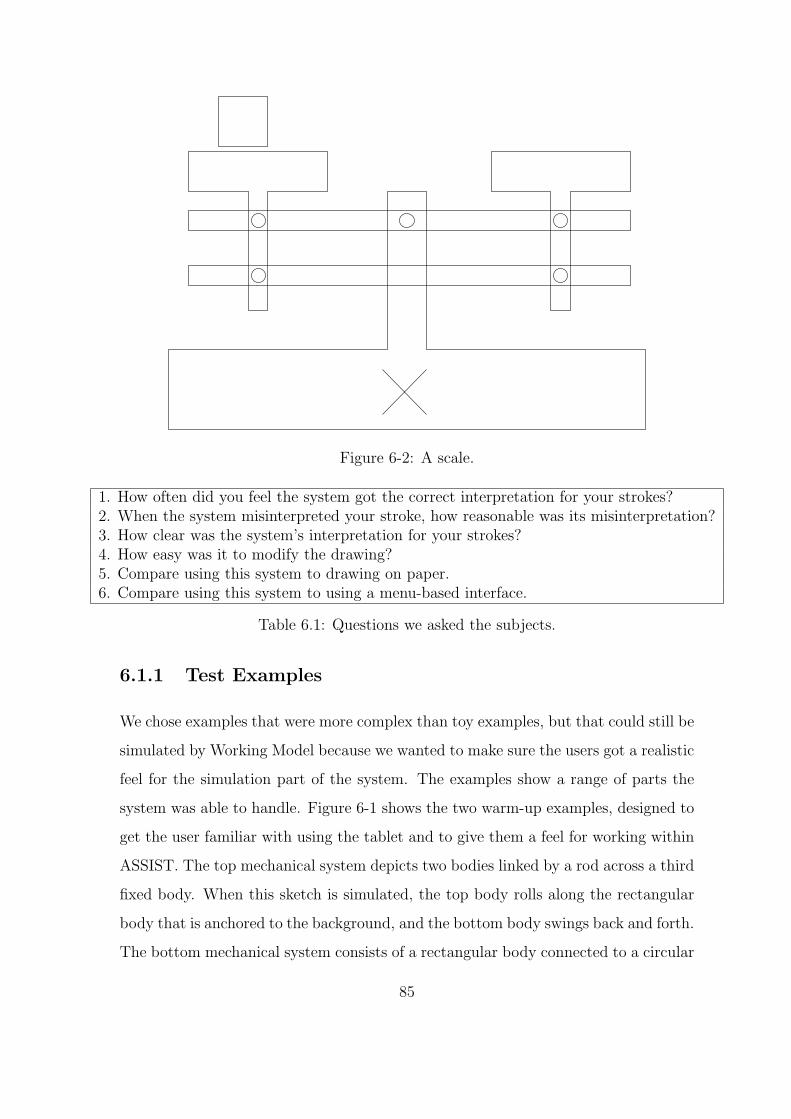
Figure 6-2: A scale.
1. How often did you feel the system got the correct interpretation for your strokes?2. When the system misinterpreted your stroke, how reasonable was its misinterpretation?3. How clear was the system’s interpretation for your strokes?4. How easy was it to modify the drawing?5. Compare using this system to drawing on paper.6. Compare using this system to using a menu-based interface.
Table 6.1: Questions we asked the subjects.
6.1.1 Test Examples
We chose examples that were more complex than toy examples, but that could still be
simulated by Working Model because we wanted to make sure the users got a realistic
feel for the simulation part of the system. The examples show a range of parts the
system was able to handle. Figure 6-1 shows the two warm-up examples, designed to
get the user familiar with using the tablet and to give them a feel for working within
ASSIST. The top mechanical system depicts two bodies linked by a rod across a third
fixed body. When this sketch is simulated, the top body rolls along the rectangular
body that is anchored to the background, and the bottom body swings back and forth.
The bottom mechanical system consists of a rectangular body connected to a circular
85

Figure 6-3: A Rube-Goldberg machine.
body with a rod, and to the background with a spring. Figure 6-2 is a scale. We
chose this example to test the system’s ability to handle overlapping shapes. There
are many areas in this drawing where the system might have become confused due
to the interactions between lines on the page. The next example is a diagram of a
Rube-Goldberg machine (Figure 6-3). It contains a large number of parts that fit
together to form a functional machine. Finally, the last system (Figure 6-4) is a rigid
body representation of a circuit breaker. We choose this example because it is an
example of a simple but realistic mechanical system.
6.2 Results
In this section, we list the features that make the system easy to use and the im-
provements that will make future versions of the system more natural.
86

Figure 6-4: A circuit breaker.
6.2.1 Drawing Style
The first observation we made concerning drawing in ASSIST was that the learning
curve for our system was small. People were able to sketch the sample mechanical
systems and have the computer recognize them with only a short training period.
While they had to slightly modify the way they drew certain objects, such as polygons
and springs, for the most part they were either able to use their natural drawing style,
or learn quickly and easily the small changes that the computer required to recognize
their drawings.1
Some people also explicitly noted what made the system feel natural: they did not
have to be in a specific mode to draw a specific piece of the sketch. One of the most
natural parts about drawing on paper is that a person can draw anything he wants
just by adding strokes to the piece of paper. Our system preserves this freedom. The
user does not have to switch to “spring mode” to draw a spring. He draws one and
the system understands what he means without him having to tell it.
On the other hand, the system does limit the user’s style in some ways due to
the hardware and the software. First, we found that some people had a hard time
getting comfortable with the hardware. Pen based hardware that allows people to
1Another member of our group is currently working to improve low level recognizers so that theyare more accurate with less constrained drawing styles.
87

draw on computers is relatively new, and while roughly the same size as paper, the
tablet is obviously much more cumbersome. Some people reported that they could
not rotate it the way they would like to; others were afraid to put their hand down
on the tablet as they would on paper, causing their drawing style to be slightly more
constrained. Finally, the design of the computer pen we used was problematic for
some: it has a button on its side that sends a signal to the computer, which in our
case, interfered with the signal that is sent by simply placing the pen on the tablet.
Because of the placement of the button, many people pressed it without meaning to,
producing unexpected behavior from the system.
Some subjects were more careful about drawing with ASSIST than they were on
paper. We told people that the drawings they produced did not have to be perfect
copies of the drawing we showed them, rather that we just wanted them to produce a
rough sketch. On paper, people seemed content to allow the drawings to be imperfect
copies of the versions we showed them. However, when they moved to the computer
some subjects became more concerned with making the drawing look neat.
We hypothesize two reasons for this behavior. First, people associate computers
with precision, and therefore might be tempted to try to make any computer-produced
drawing clean. Second, our system gives the user feedback by changing the user’s
strokes as he draws. In effect, the system cleans up the strokes in displaying an iconic
representation for them. On paper strokes stay exactly the same as the user draws
them; however, because the computer cleans up the drawing a small amount, the
subjects might have felt the need to make the drawing perfect.
6.2.2 Stroke Interpretation
Because our system interprets the user’s strokes as he draws, the user is forced to
deal with the system’s interpretations. We examined how well the system interpreted
the user’s drawings and how correcting the system’s mistakes affected the behavior
of the user and the naturalness of the system.
All users felt that the system got the correct interpretation for their strokes most
of the time. We observed two types of errors the system made: incorrect choice of
88

representation and missed interpretation. First, the system sometimes has the correct
interpretation among the many interpretations it has for a stroke, but make the wrong
decision as to which interpretation is correct. In this case the user can use the Try
Again function to tell the system which of its interpretations is correct. Second, the
system can misinterpret a stroke by not generating the correct interpretation at all.
In this case the user has to erase and redraw the stroke. We found that most of the
errors were due to the fact that the system never got the correct interpretation for
the stroke. For example, in the sketch in Figure 6-5, the system failed to interpret the
crossed lines as an anchor in the recognition step. We conclude that our reasoning
Figure 6-5: The system fails to recognize the two crossed strokes as an anchor in therecognition step.
is able to choose the correct interpretation when it is present, but we must work on
building more robust low-level recognizers for future versions of the system.
In addition to observing the types of errors the system made, we also observed
users’ error correction behavior. The Try Again button was designed to give users
a simple way to correct the system’s interpretation of a stroke or group of strokes.
However, in general users did not use the Try Again button, but instead deleted the
misinterpreted stroke and redrew it. We pose two explanations for this behavior.
First, the Try Again button was not usually helpful because, when the system got
the correct interpretation for the object in the drawing it tended to choose that object
to display. Thus, the correct interpretation in the cases where the system missed was
not usually in the interpretation list. Second, hitting “Try Again” is not an option
on paper, so it is not an option that occurs naturally to the user.
Many users also expressed frustration with not being able to modify parts of
objects. They noted that on paper they could erase parts of strokes, while in ASSIST
89

they were forced to erase whole objects. In future versions of this system we will to add
this behavior by exploiting the signal produced by the eraser end of the pen. We will
also explore the effect partial stroke deletion has on recognition and representation.
For example, when the user erases part of a box, at what point is it no longer a box
anymore?
Finally, the fact that the users knew that their strokes were being interpreted as
they drew led some subjects to be more tentative in their drawing. A few reported
the disconcerting feeling that they felt that someone was watching them and therefore
were more cautious with what they drew. Also, they were not always confident about
the computer’s interpretations and were sometimes wary because they were not sure
of the interpretation consequences of their strokes.
6.2.3 Visual Feedback
We also explored the naturalness of the visual feedback the system gave to the user.
Recall that the goal of providing the user with visual feedback was to give him an
idea of the system’s interpretation of his drawing. We found that the visual feedback
in ASSIST gave the user an unambiguous idea of how the system had interpreted the
sketch. In fact, the feedback may have been too intrusive, distracting the user as he
drew and making the system feel less natural than it might have.
Every user reported that they were always clear on what interpretation the system
had for their stroke, thus we have succeeded in always keeping the user informed.
According to subjects, the system rarely made a totally surprising interpretation for
their strokes, and when it did, subjects reported being aware immediately.
On the other hand, some users said that the way the system gave its feedback
was somewhat distracting. When the system recognizes a stroke that a user draws,
it replaces the recognized stroke or group of strokes with an icon that represents the
interpretation it has made. While this icon is fitted to match the strokes the user
has drawn as closely as possible, it still does some modification of the user’s strokes,
appearing to clean up the user’s drawing slightly. This behavior bothered some people
because they felt that they no longer had total control of the strokes they were putting
90

on the page. They reported that it was very difficult to have any sort of precision,
because they were never quite sure how the details of their stroke would end up.
We conclude from this reaction that we should find another way to give the user
clear visual feedback. We aim for a method that is just as clear, but that does
not actually modify the strokes the user puts on the page. Instead of changing the
user’s strokes, we might simply change their color, or we might display the system’s
interpretation for the stroke in a lighter shade over the user’s original stroke.
6.2.4 ASSIST as More Than Paper
It was our goal to capture in ASSIST what is natural about drawing on paper. At the
same time, we must not limit ourselves to the paper and pencil metaphor. The com-
puter allows additional actions such as rotate or copy that paper does not. Although
we are trying to build a paper-like interface, building additional, non-paper-like power
into the system can improve the system’s usability. Users described what they felt
made the system better than paper, and what they would like to see in future versions
of the system.
First, people liked the power that the system brought to the drawing process in the
realm of mechanical engineering. Subjects found the ability to simulate the drawings
to be quite appealing. Some also expressed interest in having semantic information
displayed in the drawing. For example, shading all bodies that are rigidly fixed to
the background.
People also liked the idea that the system could be a more complete editing tool.
For example, although paper does not give users the ability to cut and paste or
rotate their images, most people said that these features would not take away from
the naturalness of the interface, but simply add power that they have already come to
expect from a computer program. Also, people liked the idea that ASSIST was able
to clean up their drawings, even though they would have preferred for this cleanup
to take place after they were done drawing. Several subjects expressed interest in a
more controlled way to clean up their drawings. They wanted their strokes to be left
rough at first, with the option to go back and touch up the drawing later.
91

6.3 Summary of Study Results
The following were the main results we found from the study and their implications
on the system’s interface design.
• The system’s interpretation mistakes were most often due to the system missing
an interpretation rather than choosing the wrong interpretation for the stroke,
implying that our low level recognizers need to be improved so that the correct
interpretation is made at the base level.
• The feedback we gave the user was clear, but intrusive in the drawing process.
In future versions of the system, we will incorporate a method of feedback that
does not modify the user’s strokes.
• The learning curve for our system was extremely low.
• The aggressive recognition was effective, but slightly too aggressive. In future
versions we might wait to interpret strokes until the user has drawn a larger
piece of the sketch.
• We should give people the power to clean up their drawings (e.g. snap lines to
a grid, lock lines into polygons, etc.) because people expect this power from a
computer system.
92

Chapter 7
Related Work
Our work has been influenced by work in sketch interpretation and in mechanical
system simulation.
Similar work in sketch interpretation can be found in the Electronic Cocktail
Napkin project by Mark Gross and Ellen Yi-Luen Do (Gross, 1995; Gross, 1996;
Gross and Do, 1996). They built a system that employs a bottom-up recognition
method similar to ours. Their system also has a method for representing ambiguity
in the user’s sketches, and is capable of refining its interpretations of the user’s stokes
after the appropriate context has been set into place.
Our system differs from theirs in that it takes a more aggressive approach to am-
biguity resolution, and therefore can interpret more complicated interactions between
parts. The Electronic Cocktail Napkin is capable of recognizing ambiguity and stor-
ing it internally, as our system does. However, in order to resolve this ambiguity,
the user must either inform the system explicitly of the correct interpretation of the
stroke, or the system must find a specific higher-level pattern that would provide the
context to disambiguate the interpretation of the stroke. Our system, in contrast,
takes into account not only drawing patterns but also knowledge of drawing style and
user expectations.
A second sketch recognition system is the SILK (Sketching Interfaces Like Krazy)
system by James Landay (Landay and Meyers, 1995). SILK is a recognition system
that allows the user to sketch out rough graphical user interface designs, and then
93

transform them into more polished versions as the design becomes more stable.
SILK also addresses the notion of ambiguity in the sketch, but is limited to its
handling of ambiguity of single parts, e.g. is this group of strokes a radio button
or a check box? Whether a group of strokes is a check box or a radio button does
not affect the interpretation of the other strokes in the sketch. In contrast, our
system can resolve compound ambiguities. That is, whether a stroke is a rod, or
the side of a box affects how the other lines that would have made up the box can
be interpreted. Thus, SILK can simply keep track of ambiguities and allow the user
to specify her interpretation later, while ASSIST uses knowledge of the domain to
resolve ambiguities as the user sketches.
A theoretical motivation to our work was provided by work by Eric Saund and
Tomas Moran. Saund and Moran outline several goals in interpreting ambiguous
sketches (Saund and Moran, 1994; Saund and Moran, 1995). Our work implements
many of the multiple representation and disambiguation techniques suggested in their
work.
We have also been motivated by work in mechanical system behavior analysis,
especially in the field of qualitative behavior extraction and representation (Sacks,
1993; Stahovich et al., 1997). An important part of our system will be to interpret
the behavior of the systems that people draw so we can transfer them intelligently to
the next stage of the design process (i.e. a CAD program) and interact intelligently
with the designer as he is sketching out his design.
A good example of work in this area is Tom Stahovich’s SketchIt system (Sta-
hovich, 1996). SketchIt attempts to understand the mechanical relationships between
parts in a sketch. When people sketch, they draw approximations of the actual sys-
tem they are designing. Stahovich aims to extract the important design constraints
from the designer’s rough sketch. While Stahovich’s goal is also to create a sketch
based interface for the early stages of mechanical design, he focuses on the relation-
ship between the device behavior and the recognition of the sketch, rather than on
creating a natural sketching interface or noticing and resolving visual ambiguities in
the sketch.
94

Chapter 8
Future Work
The work presented here is a first step toward creating natural and powerful sketch
based interfaces for mechanical systems. It can be expanded and improved in many
directions, from improving the base level recognition to adding behavioral intuition
to produce more natural simulations of the user’s sketches. In this chapter we present
some directions for future work that will make for a more intuitive system.
8.1 Low Level Recognizers
ASSIST used an algorithm for separating strokes into line segments that was based
only on the pixel data of the stroke. A more robust algorithm would incorporate
stroke speed data to divide a user’s stroke into line segments. When people draw
polygons, they tend to slow down in the corners. This data, when combined with the
pixel data makes for robust recognition of line segments. Currently recognition of line
segments from single strokes is the weakest part of the low-level recognition system.
A member of our group is already working on improving the base level recognition of
single stroke, multiple line segments.
Our system relies mainly on bottom-up processing to make interpretations. It uses
top-down pattern recognizers to fit strokes together, but the top-down processing only
serves to organize all the low-level information, rather than prune it or merge it. For
example, when the user draws a square using four strokes, the system has no problem
95

recognizing it as a square. If, on the other hand, the user draws a square using eight
strokes, over-tracing parts of previously drawn strokes with each new stroke, the
system will not recognize the shape as a square. It has no way of collapsing strokes
into sides; it assumes that all strokes are equally important and that they contribute
a significant amount to the object they are a part of. We want our system to be able
to detect higher level shapes regardless of the strokes used to draw the shapes.
8.2 Sketching Using the Computer as a Tool
We discovered during user testing that people did not want the system to behave
exactly like paper—they wanted the benefits of the computer combined with the
naturalness of paper.
People were interested in the idea of a sketch program on the computer because
they imagined a sketch-based recognition program as a first level to an interface that
would improve the user’s drawing incrementally as he worked. In an ideal scenario, a
person sketches exactly as he would on paper. As he sketches the computer does not
touch his strokes, rather just recognizes them. When he finishes, the system replaces
his drawing with cleaned up version, with all the parts neatly aligned. Because it is
distracting to have this realignment happening in the initial stages of sketching, the
clean-up process should be delayed until the user is done sketching.
Next, the editing in ASSIST needs to be expanded for it to be a useful tool in
practice. It would be nice to have the best of both drawing on paper and editing
on the computer. When people want to modify part of a sketch, they often want to
erase as they would on paper. At the same time, they want to use features such as
copy, paste and rotate to edit their sketches. Adding such features would make the
computer less like paper, but would likely not limit the natural feeling of the interface.
96

8.3 Learning and Adaptation
Another area we would like to focus on involves adapting to an individual’s use of the
system. The system should be flexible and extendable, not only learning a specific
user’s style, but also learning novel patterns that it had not seen before.
Each user has his own style of drawing. The system should learn to expect each
user’s style, making the system more robust at recognizing a user’s strokes. We have
embedded into the system a certain amount of knowledge about mechanical system
drawing. However, we cannot not predict the drawing styles of individuals. While
the system is natural to some, many of the test subjects found some of the icons to
be slightly restricting. For example, many people had trouble getting the system to
recognize a spring because they drew it in a way the system did not expect. The
system should be able to learn what to expect from specific users.
Learning can also be applied at the reasoning level. A priori, we cannot account
for all the drawing heuristics that people use. For example, we stated that one of
our heuristics was that people draw all of one object before moving onto the next.
However, we found that some people’s drawing pattern does not fit into this style.
When drawing aligned bodies such as the ones in Figure 3-1, some subjects drew
all the horizontal lines before drawing any of the vertical lines. The system should
be able to learn this type of behavior, even though it goes against one of its initial
heuristics.
Another way that the system should be able to learn is by learning new objects to
recognize. This idea was implemented by Gross (Gross, 1996) and suggested in the
context of RecSystem by Weisman (Weisman, 1999).
8.4 Adding Intelligent Behavior
Finally, we would like to improve ASSIST from a mechanical engineering standpoint.
Currently we have a system that recognizes mechanical sketches. However, once it
recognizes pieces of the sketches, it can only naıvely work with the system. We want
97

to incorporate a more intelligent interpretation of the behavioral aspects of the sketch
so that it can be used for design rationale capture and take a more active role in the
design process.
To illustrate the point about behavior, consider the circuit breaker example (Fig-
ure 6-4). A person looks at the example and “sees” the expected behavior: the force
on the latch pushes it downward, the spring attached to the lever at the top pulls it to
the right until it hits the plunger and sits at rest until someone resets it. Now contrast
this view of the behavior with the literal interpretation using Working Model: the
force pushes down on the latch, but the system does not know it is only supposed to
be applied for a short period of time, so the lever oscillates up and down. The spring
attached to the latch at the top is assumed to be at rest, so it does not pull the lever
out to hit the plunger. The plunger does not fit tightly into the “wall”, and bounces
around when hit.
A first step towards behavioral intelligence is an annotation method being devel-
oped by another member of our group. His goal is to allow the user to inform the
system of the behavior through speech and gesture information. For example, a user
might draw the system in Figure 8-1 and say “The block pushes the ball forward until
it rolls down the ramp and off the other side”(Oltmans, ). The system would then
Figure 8-1: An example used in describing annotations.
know how to set the length and constant of the spring to get the system to produce
98

the desired behavior. We can draw on work in literal and qualitative simulation to
help our system understand more about intuitive behavior.
99

100
Chapter 9
Conclusion
Engineers currently do not use computers in early design because the iconic interface
of CAD and simulation tools do not allow them to record their ideas quickly and
naturally. To be useful in early design, computers must allow the designer to sketch
as she does on paper and provide her with benefits, such as the ability to simulate
her system, that she does not have on paper.
Our goal is to create an assistant that can understand the engineer’s design as
she sketches freely. A necessary first step is to get the computer not just to represent
ambiguities in the drawing, but to resolve them as quickly and easily as humans do.
We created a natural sketching interface by building a program that would recognize
a designer’s mechanical sketch more or less the way a human observer would. Our
program allows the user to sketch mechanical systems and then simulate these systems
using a two dimensional kinematic simulator. We also presented a general framework
in which to incorporate domain-specific knowledge to resolve ambiguities in a user’s
sketch. Instead of simply recognizing and storing ambiguities, our system combines
user feedback and knowledge of mechanical engineering design, and properties of
sketching to present the user with the most likely interpretation for her sketch.
This work provides a base upon which future applications can be built, bringing
us one step closer to the vision of a computer tool for the entire design process — a
tool that engineers would be willing to use instead of sketching on paper, instead of
in addition to it.
101

102

Bibliography
Artobolevsky, I. I. (1976). Mechanisms in Modern Engineering Design, volume 1.
MIR Publishers, Moscow.
Biederman, I. (1987). Recognition-by-components: A theory of human image under-
standing. Psychological Review, 94(2):115–147.
Corning, W. C. and Balaban, M., editors (1968). The Mind: Biological Approaches
to its Functions, chapter 7, pages 233–258. Interscience Publishers.
Gross, M. and Do, E. Y.-L. (1996). Ambiguous intentions: a paper-like interface for
creative design. In Proceedings of UIST 96, pages 183–192.
Gross, M. D. (1995). Recognizing and interpreting diagrams in design. In 2nd Annual
International Conference on Image Processing, pages 308–311.
Gross, M. D. (1996). The electronic cocktail napkin - a computational environment
for working with design diagrams. Design Studies, 17:53–69.
Jurafsky, D. and Martin, J. H. (2000). Speech and Language Processing: An Intro-
duction to Natural Language Processing, Computational Linguistics, and Speech
Recognition. Prentice-Hall.
Kolb, B. and Whishaw, I. Q. (1996). Fundamentals of Human Neuropsychology. W.
H. Freeman and Company, fourth edition.
Landay, J. A. and Meyers, B. A. (1995). Interactive sketching for the early stages of
user interface design. In The Art of Human-Computer Interface Design Conf.,
pages 43–50. ACM Press.
103

Mahoney, J. (1987). Image chunking: Defining spatial building blocks for scene
analysis. Master’s thesis, Massachusetts Institute of Technology.
Muzumdar, M. (1999). ICEMENDR: Intelligent capture environment for mechanical
engineering drawing. Master’s thesis, Massachusetts Institute of Technology.
Oltmans, M. Understanding multimodal descriptions of device behavior. Unpublished
Master’s Thesis.
Palmer, S. E. (1975). The effects of contextual scenes of the identification of objects.
Memory and Cognition, 3:519–526.
Sacks, E. (1993). Automated modeling and kinematic simulation of mechanisms.
Computer-Aided Design, 25(2):107–118.
Saund, E. and Moran, T. P. (1994). A perceptually-supported sketch editor. In
Proceedings of ACM Symposium on User Interface Software and Technology.
Saund, E. and Moran, T. P. (1995). Perceptual organization in an interactive sketch
editing application. In ICCV 1995.
Stahovich, T. (1996). Sketchit: a sketch interpretation tool for conceptual mechanism
design. Technical report, MIT AI Laboratory.
Stahovich, T. F., Davis, R., and Shobe, H. (1997). Qualitative rigid body mechanics.
In American Association of Artificial Intelligence Conference Proceedings, pages
138–144.
Ullman, D. G., Wood, S., and Craig, D. (1990). The importance of drawing in
mechanical design process. Computer & Graphics, 14(2):263–274.
Ullman, S. (1996). High Level Vision. MIT Press.
Weisman, L. (1999). A foundation for intelligent multimodal drawing and sketching
programs. Master’s thesis, Massachusetts Institute of Technology.
104