Clinical Quality Measure (CQM) Tim Proctor ([email protected] ...
date post
19-Dec-2015Category
view
218download
0
P11017: Tactile Navigation InterfaceChristian SeemayerRob ProettiTim DeBellisTim GiguereWill Kelly
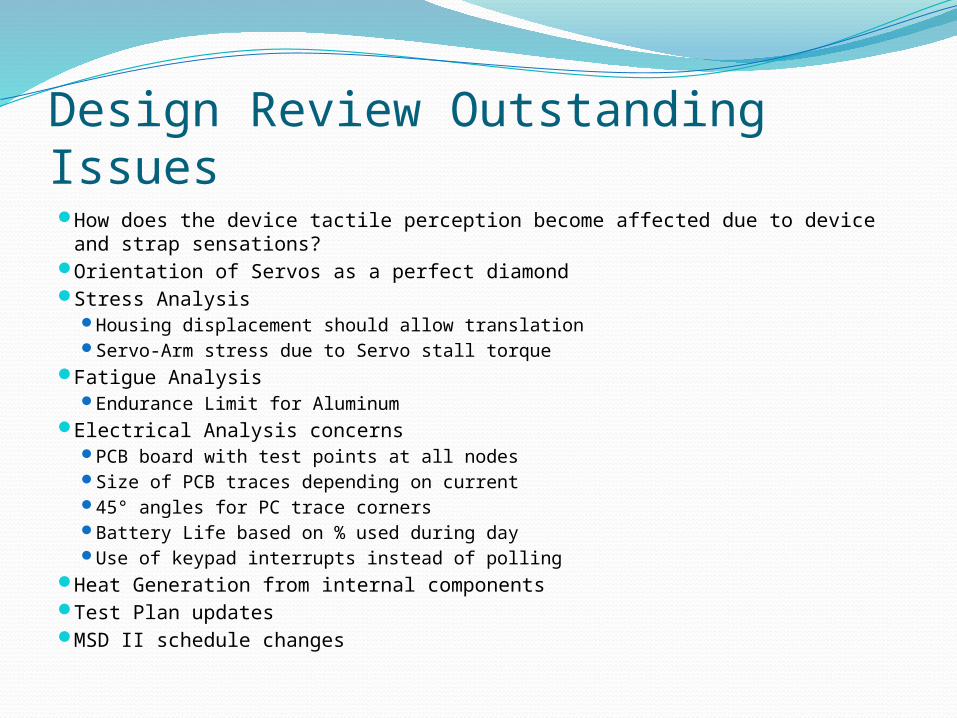
Design Review Outstanding Issues How does the device tactile perception become affected due to device and
strap sensations? Orientation of Servos as a perfect diamond Stress Analysis
Housing displacement should allow translation Servo-Arm stress due to Servo stall torque
Fatigue Analysis Endurance Limit for Aluminum
Electrical Analysis concerns PCB board with test points at all nodes Size of PCB traces depending on current 45° angles for PC trace corners Battery Life based on % used during day Use of keypad interrupts instead of polling
Heat Generation from internal components Test Plan updates MSD II schedule changes
Device and Strap Sensation EffectsMeeting at ABVI on 2/18/2010 with Alexis
Read and Richard What we discussed
Retested more tip designs out of curiosity with preference being large bowl shape (Screw head)
Concept of generating diagonal directions through pulsing
Directional Testing (2 Tests) Basic Test Armband and weight applied Test
What We LearnedResults: 100% accuracy from participants. Extra sensations demonstrated no effect on accurate
direction interpretation. Direction recognition training quicker then expected.
Short (~1 minute)training period Proper Training approach – Diamond Construction
Participants disliked diagonal direction idea4 directions good, 8 creates confusion.
Revamped analysis based on recommendations from Design Review
Put tiny clear dots on the buttons (For sale in Vision Shop at ABVI, 6 dots for $2)
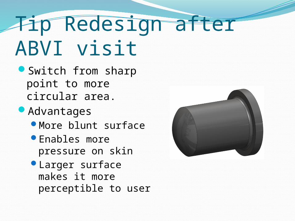
Tip Redesign after ABVI visitSwitch from sharp
point to more circular area.
AdvantagesMore blunt surface Enables more
pressure on skinLarger surface makes
it more perceptible to user
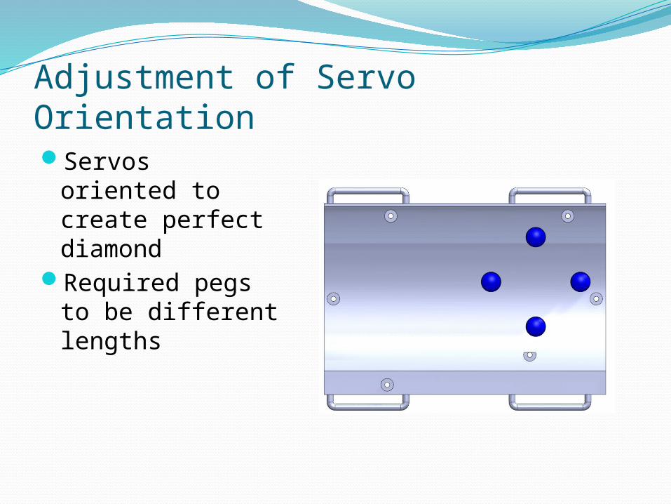
Adjustment of Servo OrientationServos oriented
to create perfect diamond
Required pegs to be different lengths
Stress Analysis: HousingDevice Housing
Switched boundary condition from All DOF to fixed displacement in load direction
Accounted for translation that can occur.Servo-Arm
Accounted for servo stall torque
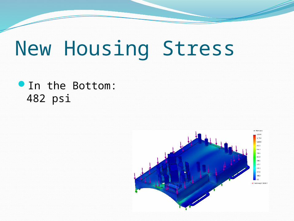
New Housing Stress
In the Bottom: 482 psi
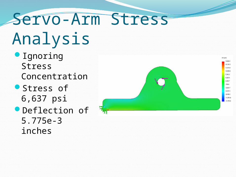
Servo-Arm Stress AnalysisIgnoring Stress
ConcentrationStress of 6,637
psiDeflection of
5.775e-3 inches
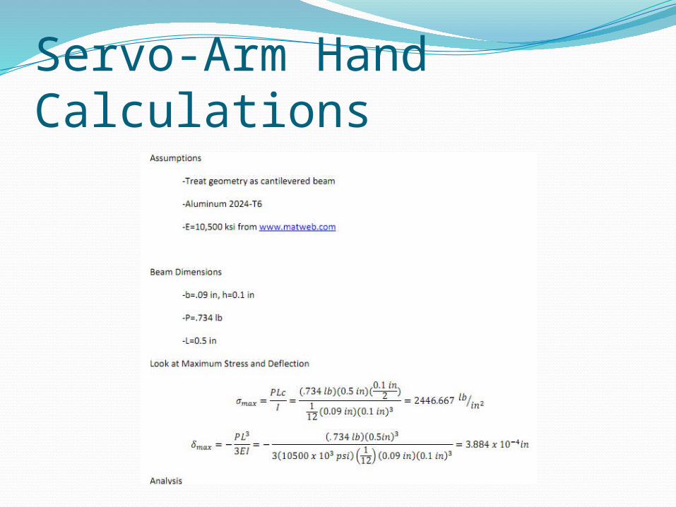
Servo-Arm Hand Calculations
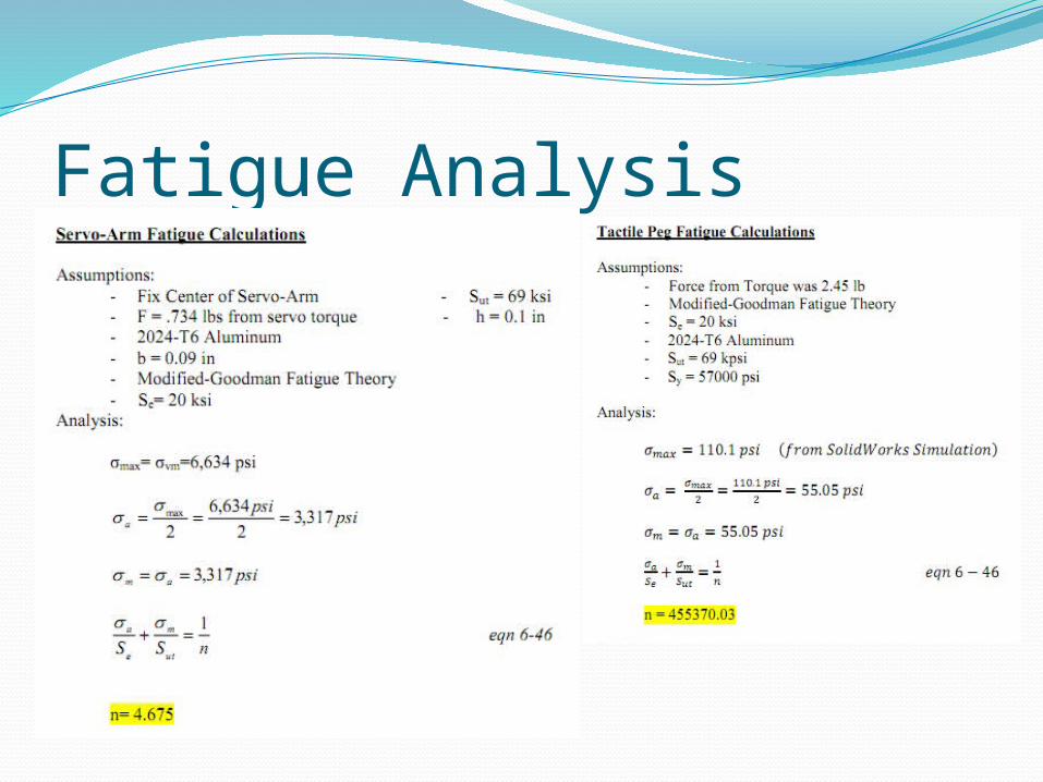
Fatigue Analysis
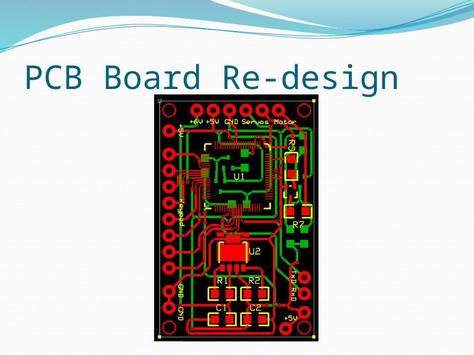
PCB Board Re-design
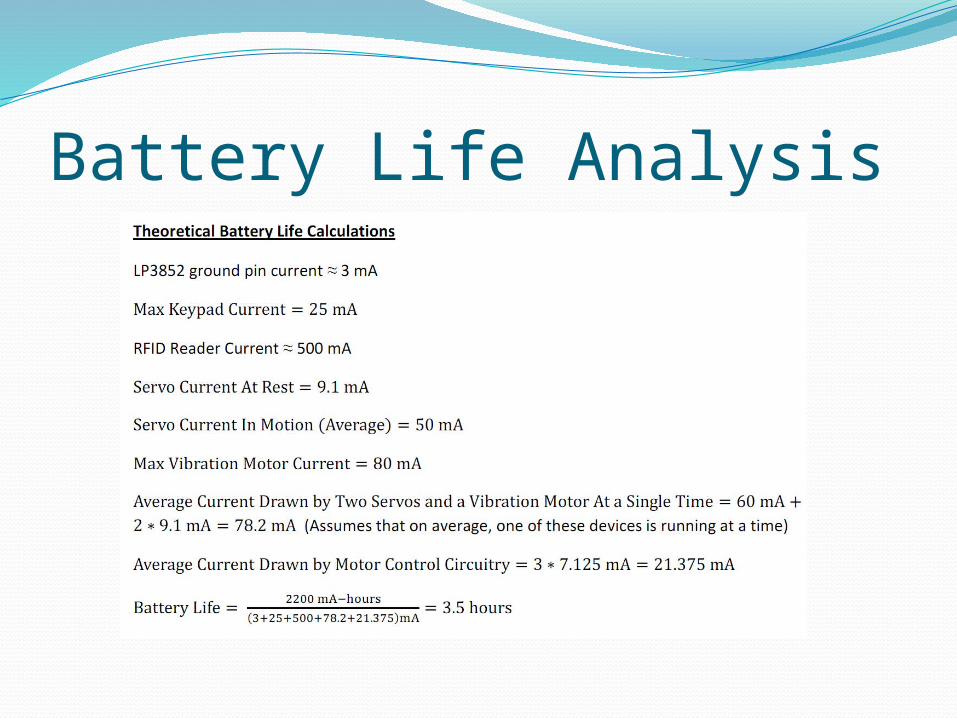
Battery Life Analysis
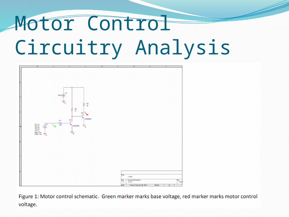
Motor Control Circuitry Analysis
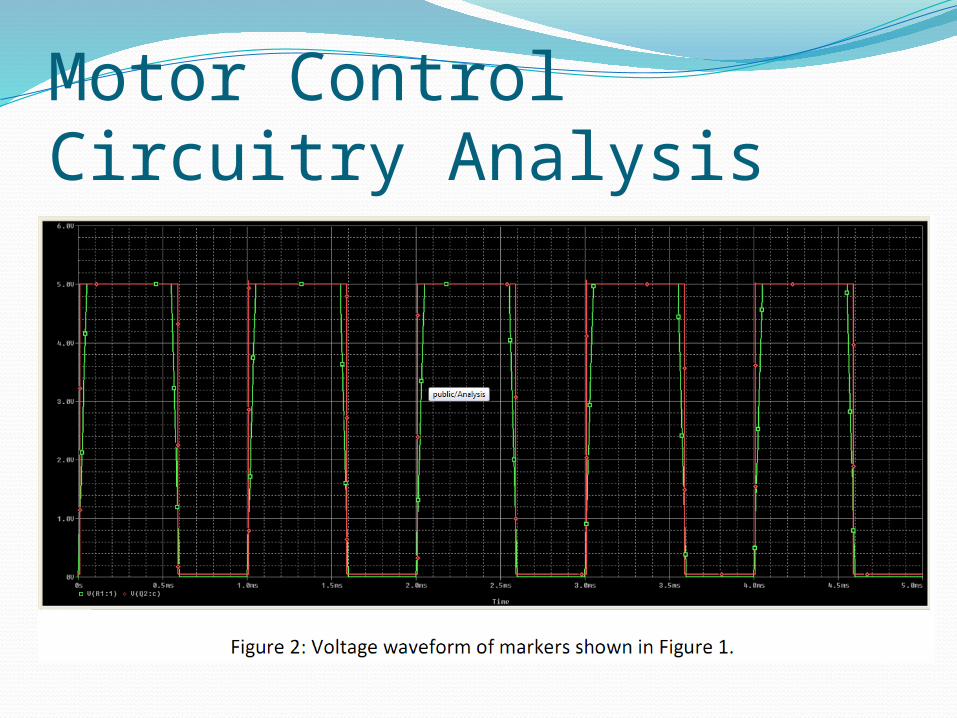
Motor Control Circuitry Analysis
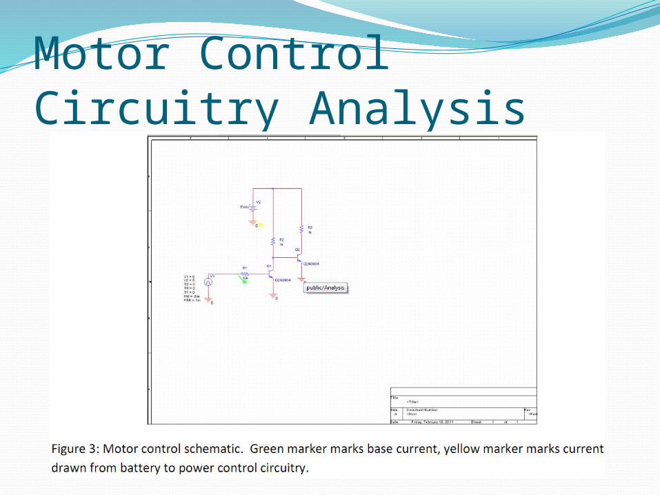
Motor Control Circuitry Analysis
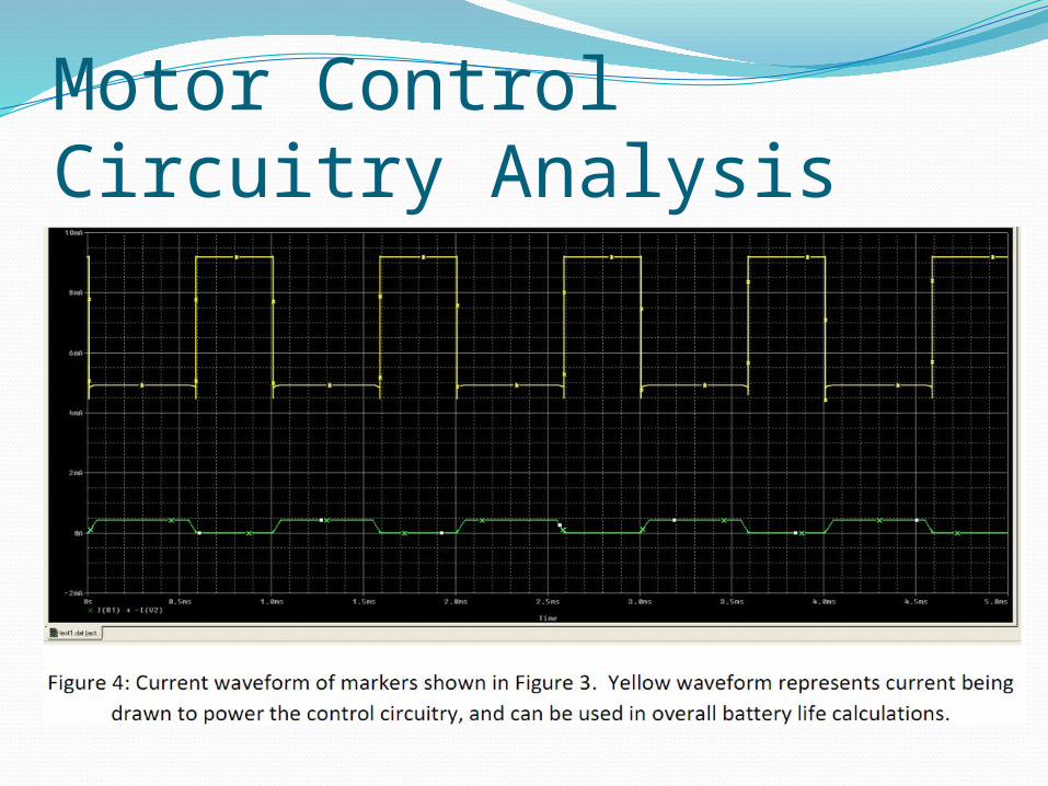
Motor Control Circuitry Analysis
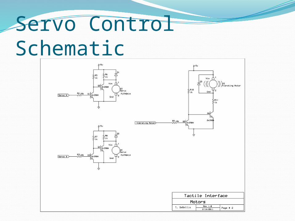
Servo Control Schematic
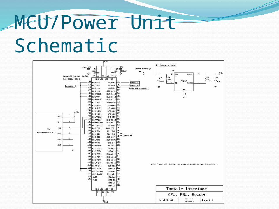
MCU/Power Unit Schematic

Team Interfacing DataCompletely new documentReview posted document on EDGE under
Miscellaneous Documents

Heat Generation Effects
Test Plan UpdatesListed engineering specifications correlated to each test
Can be found under test description and on Specs PageAddition of Test #3 – Electronic Component Testing
Aims to test individual components to ensure proper functioning before beginning assembly period
Eliminated Destructive Tests (Device Drop and Compression)Moved up test dates in scheduleRearranged testing order to account for test with similarities
Direction Relay Test to be conducted with Servo Positioning Test On/Off Switch Test to be conducted in Week 2 or 3 based upon
assembly
MSD II UpdatesTest Plan Date updates incorporated directly into
scheduleCreated a more specific focus on machining of
componentsCreated a focus toward part assembly times for both
mechanical and electrical componentsRough Draft of paper to be started Week 3
75% complete by Week 8Final draft by Week 9
Rough Draft of Poster constructed for Imagine RITTo be finalized during Week 10
Project Plan for MSD I has helped define each member’s role within the team and establish reasonable goals
Evolution of Overall Project PlanDriven to focus on customer needs
Created specific and sometimes last minute alterations
Altered to account for switches in project design
Accounted for simplification of overall project goalDevice becoming stand alone with self inputs
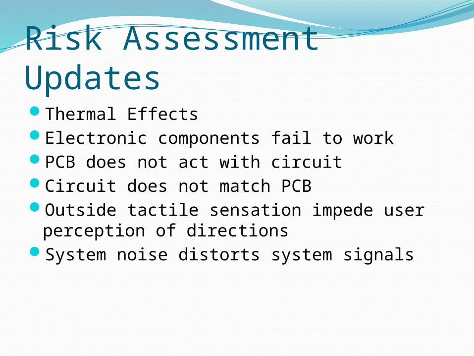
Risk Assessment UpdatesThermal EffectsElectronic components fail to workPCB does not act with circuitCircuit does not match PCBOutside tactile sensation impede user
perception of directionsSystem noise distorts system signals
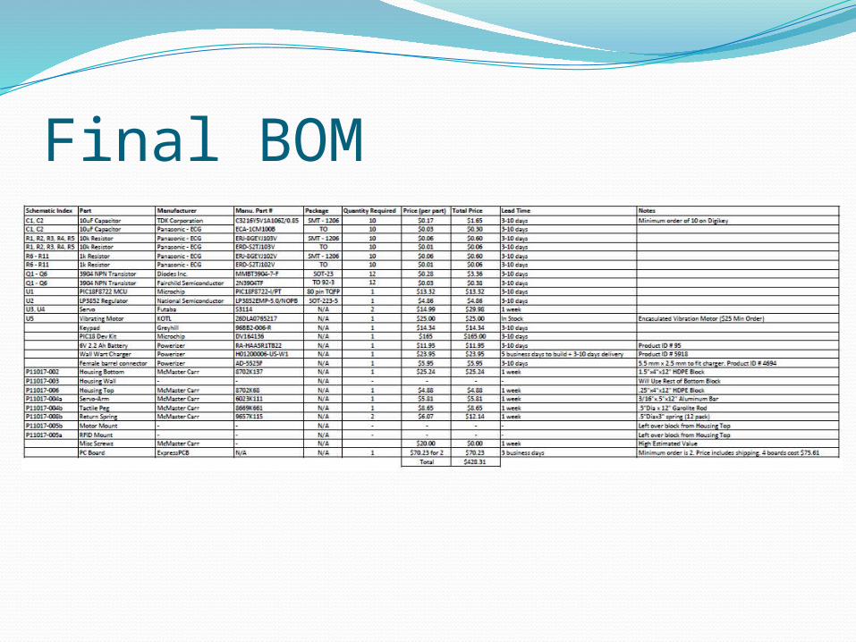
Final BOM
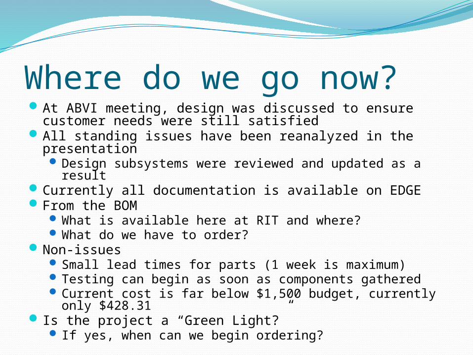
Where do we go now?At ABVI meeting, design was discussed to ensure customer
needs were still satisfiedAll standing issues have been reanalyzed in the
presentation Design subsystems were reviewed and updated as a result
Currently all documentation is available on EDGEFrom the BOM
What is available here at RIT and where? What do we have to order?
Non-issues Small lead times for parts (1 week is maximum) Testing can begin as soon as components gathered Current cost is far below $1,500 budget, currently only
$428.31 Is the project a “Green Light?”
If yes, when can we begin ordering?