How a LERTA Could Expand Business in Berks County Presented by: Christian Y. Leinbach.

1 Revised 10/27/2020
Christian County TYPICAL DECK REQUIREMENTS
The following construction guidelines are for one and two-family residential decks
These guidelines are for single-level and roof covered single-level deck construction. Any deck design or
decks supporting additional loads may be subject to an approved engineer design.
A Permit is required for any deck that meets at least one of the following:
• Exceeds 200 square feet
• More than 30” above grade at any point
• Will be attached to the dwelling
• Serves the required exit door
All exterior decks are considered as permanent structures and required to follow the guidelines as
described in the document.
Exception: Decks for manufactured housing (mobile homes) are required to be free standing and
are subject to approval at the final inspection.
The proposed deck or decks shall be included on the required floor plan when applying for a one and two-
family residential building permit. The deck plan shall include the size, location and dimensions.
RESIDENTIAL WOOD DECK CONSTRUCTION GUIDE
Courtesy of American Wood Council - Leesburg, VA

2 Revised 10/27/2020
ROOF COVERED SINGLE LEVEL DECK REQUIREMENTS ARE ON PAGE 12
GENERAL NOTES:
1. Decks constructed according to this appendix are not approved for future hot tub installations.
2. All decks that require a permit must include a plan submission. (See page 13 for details)
3. It is the responsibility of the permit holder or the permit holder’s representative to notify the
County when the stages of construction are reached that require an inspection. Inspection requests
may be made by contacting the Christian County Building Regulations at 417-581-6064, 8:00
a.m. to 4:00 p.m., Monday - Friday.
4. A footing, framing, and final inspection is required on all decks.
• Footing inspections are required PRIOR to the placement of concrete.
• Framing and final inspections may be combined if all portions of the deck framing and
ledger attachments are at least 42” above grade and visible.
• Inspections are required by law. Failure to receive any and all inspections can result in
the issuance of violations which may lead to legal action.
5. Decks shall not be used or occupied until a final inspection approval is obtained.
DESIGN LOADS:
Decks are required to be designed to support a live load of 40 pounds per square foot. Guardrails are
required to be designed to support a load of 200 pounds applied to a concentrated point along the top of
the rail.
DECK MATERIAL:
All lumber shall be #2 grade or better. Decks shall be constructed of either naturally decay-resistant or
pressure-treated lumber according to American Wood-Preservers’ Association. All lumber in contact
with the ground shall be rated as “approved for ground contact”. Alternate construction material must
have prior approval by the Chief Building Official.
CONNECTIONS:
All connections shall be hot-dipped galvanized or stainless steel. These connectors include bolts, screws,
nails, joist hangers, post anchors, flashings and all other connectors.
All carriage bolts and lag screws are required to be a minimum of one-half (1/2) inch in diameter or have
prior approval from the Chief Building Official. All carriage bolts and lag screws shall be placed a
minimum of two (2) inches from the ends and edges of lumber. The pilot holes for the installation of the
carriage bolts and all-thru-bolts are required to be the same diameter as the bolt. Pilot holes for lag
screws shall be drilled one-eighth (1/8) inch smaller than the diameter of the lag screw and shall not
exceed three-quarters (3/4) of the combined length of the screw shank and thread length

3 Revised 10/27/2020
FOOTINGS:
All deck posts are required to be supported by concrete footings. The footings shall be a minimum of
sixteen (16) inches in diameter, eight (8) inches thick and eighteen (18) inches deep from finished yard
grade. Footings are to be placed on undisturbed or compacted soil. If fill is used a compaction report
may be required before the footing is approved. Slabs supporting posts shall have the approved footings
directly under the support locations. Precast piers will not be allowed.
All footings are required to be inspected prior to placing concrete. These inspections may be incorporated
with other on-site inspections during the dwelling construction.
POST:
All decks are required to have a minimum of a 6” x 6” support post at all required support locations.
Support posts are required to be placed apart at a maximum of eight (8) feet on center with a maximum
height of fourteen (14) feet from the top of the footing to the bottom of the girder or beam (single level
deck with no roof load only). When possible, the posts should extend a minimum of 36 inches above the
floor for the guard rail support (see guard rail requirements, Pages 11 and 12). Notching of posts shall
only be allowed for beam connections (see beam requirements, Page 4).
All posts are required to be supported by concrete footings. The posts shall be attached to the concrete to
resist lateral movement and uplift. Drift pins or bolts placed in the concrete and thru the center of the post
will not be approved.

4 Revised 10/27/2020
BEAMS:
All beams shall be two (2) plys of the sized floor joist required and span a maximum of eight (8) feet.
The beam shall be assembled by attaching the two members together staggering every six (6) inches with
either #10 ring shank nails or #10 screws. All butt joints are required to be a minimum of two (2) feet
apart. Each end of the beam assembly shall be connected together with two (2) #10 ring shank nails or
two (2) #10 screws. Solid beams (4 x 12) are recommended when available.
Split beams (one member on each side of the post) shall require solid blocking between the two members.
The blocking shall be placed every two (2) feet apart and securely fastened together to make a single unit.
Split beams can only be used on interior support posts or under cantilever floor joists. Floor joists must
always sit on the top of a split beam and never connected to the side.
Beams cannot cantilever more than two (2) feet beyond their support post.
Support posts for single level decks only (no roof load) shall be notched three (3) inches in depth to carry
the 2x beam. Support posts for roof covered single level decks shall be notched one and one-half (1 ½)
inch in depth with an attached 2” x 6” x 4’ leg under the outside ply of the beam. The beam shall be
attached to the post with two (2) one-half (1/2) inch carriage bolts and washers.
outside floor joists are not beams and should be bolted to the corner support post, not notched into the
post.

5 Revised 10/27/2020
FLASHING:
Flashing is required to be placed under the siding or exterior finish system prior to the installation of the
ledger board. Flashing is required at any ledger board connection to a wall of wood framed construction.
The flashing shall extend over the top of the ledger. Flashing material shall be copper (attached using
copper nails), stainless steel, UV resistant plastic or zinc plated (1.85 oz/sf) galvanized steel.
DECK LEDGER ATTACHMENT:
All deck ledgers are required to be attached to a minimum of a two (2)-inch thick dimensional lumber
band board or a one and one-quarter (1 ¼)-inch manufactured solid band board. Band boards or house
rim joists are required to be supported entirely by the house foundation wall.
Ledgers consisting of either a 2 x 10 or 2 x 12 dimensional lumber are required to be attached to the
house band board or rim joist with one-half (1/2)-inch carriage bolts, lag screws or pre-approved fasteners
in a double/single/double pattern spaced at sixteen (16) inches on center. Ledgers consisting of 2 X 8
dimensional lumber may be attached in a staggered pattern spaced at sixteen (16) inches on center using a
minimum of one-half (1/2)-inch carriage bolts, lag screws or pre-approved fasteners.
Lag screws shall extend past the interior side of the house rim joist a minimum of one-half
(1/2)-inch, but no greater than one (1)-inch.

6 Revised 10/27/2020
ATTACHING A DECK TO A CANTILEVER:
Decks shall not be attached to cantilevers unless approved by the Chief Building Official!
The house cantilever may be headed off outside with an approved double joist/header system. This
system must be approved by the Chief Building Official or engineer designed and approved. Any
deviation from this design or attaching to existing cantilever shall require additional outside support.
The deck may be self-supporting.
Solid blocking between the joists is required over the exterior wall.
The underside of the cantilever cannot be covered until the cantilever is inspected and approved. This
inspection will occur at the rough-in inspection. When the cantilever is one floor or more above grade, a
ladder must be provided at the time of the inspection.
FLOOR JOISTS:
The following floor joist span table is based on using #2 Southern Pine with a live load of 40 pounds per
square foot and a dead load of 10 pounds per square foot.
MAXIMUM FLOOR JOIST SPANS
Joist Size Joist Spacing,
on center
Joist Span
excludes overhangs
2x6 16" 9'-4"
2x6 24" 7'-10"
2x8 16" 12'-2"
2x8 24" 10'-1"
2x10 16" 15'-9"
2x10 24" 13'-1"
2x12 16" 18'-0"
2x12 24" 15'-4"

7 Revised 10/27/2020
Joist hangers are required for the attachment of floor joists to the ledger and beam supports. When
clearances do not allow for the conventional joist hangers with outside flanges, then joist hangers with
inside flanges are allowed. Joist hangers must be installed with approved fasteners. Pressure blocks
between the joists are not allowed.
Floor joists cannot cantilever more than three
(3) feet. The cantilevered joist must back
span two (2) times the cantilever distance.
Example: A cantilever from a supporting
beam three (3) feet in length must span in the
opposite direction a minimum of six (6) feet.
GUARDRAIL REQUIREMENTS:
All decks with a floor height greater than thirty (30) inches above finish yard grade are required to have a
guard rail. Guardrails shall be a minimum thirty-six (36) inches in height.
Whenever possible the guardrail supports should be the posts that support the deck. These supports
should extend above the deck floor a minimum of thirty-six (36) inches and a maximum of eight (8) feet
apart.
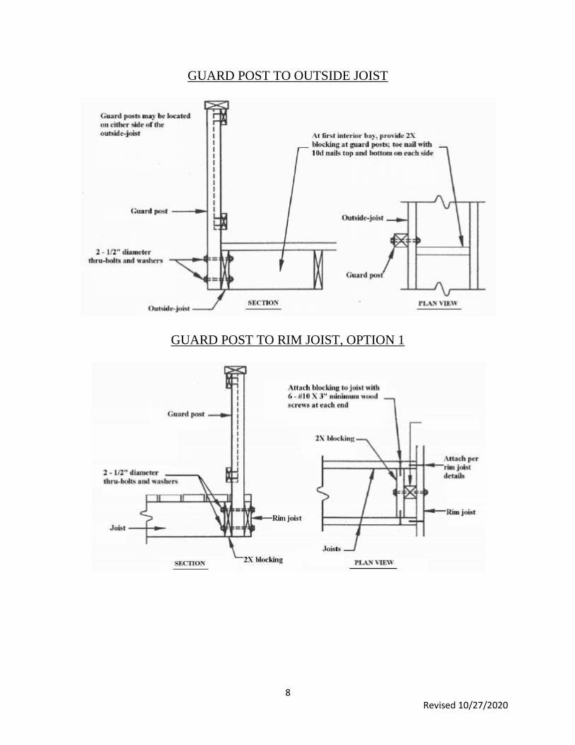
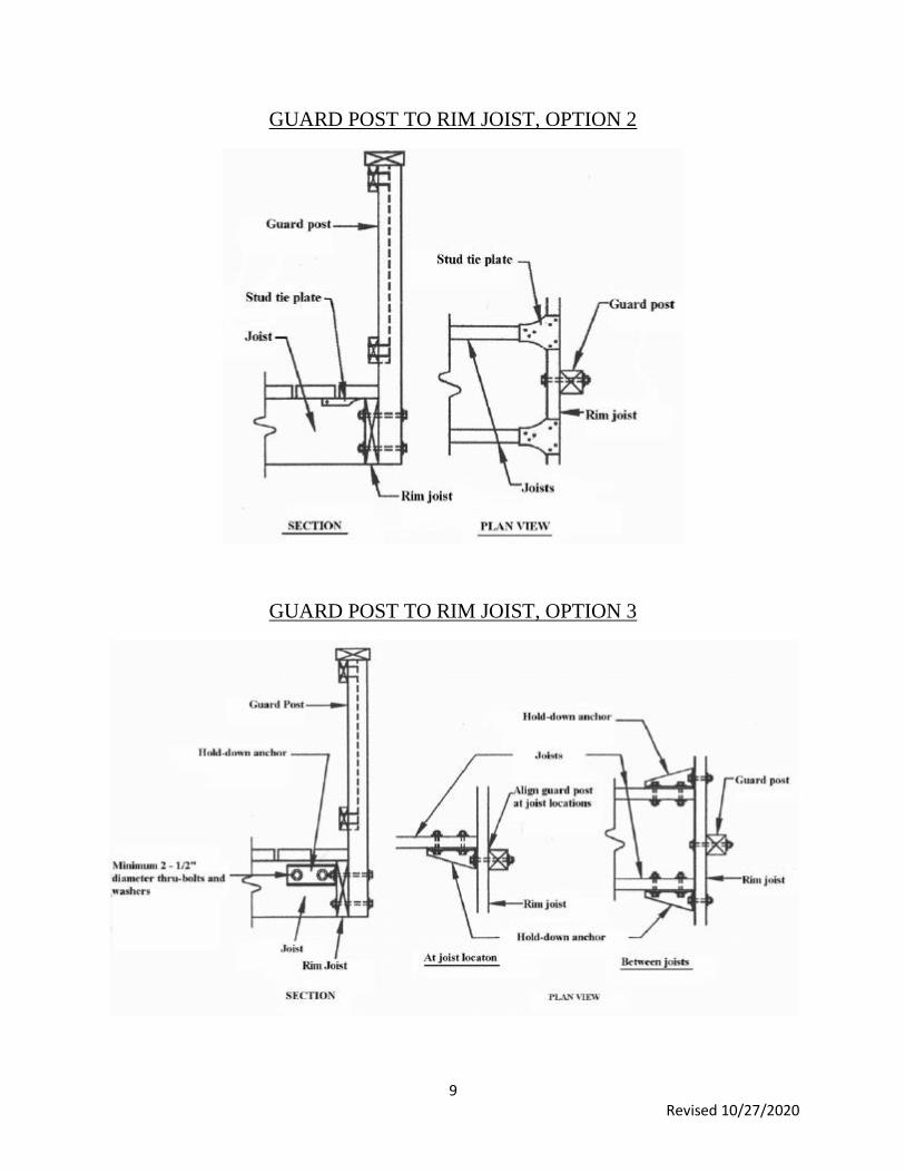
INDEPENDENT GUARDRAIL POST:
Independent guardrail posts shall be a minimum of 4” x 4”. Guardrail posts shall be placed at all corners
of the deck and a maximum of six (6) feet on center. Guardrail posts shall not be notched. All corner
guardrail posts shall be secured to the rim joist or outside joist with four (4) one-half (1/2) inch carriage
bolts two (2) bolts on each side of the corner. All other guardrail posts shall be secured to the rim joist or
outside joist with two (2) one-half (1/2) inch carriage bolts.
SEE FOLLOWING ILLUSTRATIONS FOR GUARDRAIL INSTALLATIONS
8 Revised 10/27/2020
GUARD POST TO OUTSIDE JOIST
GUARD POST TO RIM JOIST, OPTION 1
9 Revised 10/27/2020
GUARD POST TO RIM JOIST, OPTION 2
GUARD POST TO RIM JOIST, OPTION 3

10 Revised 10/27/2020
STAIRWAYS:
Stairways shall be a minimum of thirty-six (36) inches wide (clear egress) in the direction of travel.
Stairways shall require three (3) stringers with a maximum span of nine (9) feet between supports. All
stringers shall be 2 x12’s, #2 or better lumber. The tops of all stringers shall be seated entirely on the rim
joist. The stringers can be attached to the rim joist by placing pressure blocks between stringers and
attaching the stringers to the rim joist and the pressure blocks. The stringers may also be secured by using
sloped joist hangers or Simpson LS70 or similar approved gusset angles.
Stairways and their landings shall be supported by 6”x 6” posts. Posts are to be placed on sixteen (16)
inch diameter footing pads. Footing pads shall be a minimum of eight (8) inches thick and eighteen (18)
inches below finished grade. Footings placed closer than five (5) feet from the exterior wall of the house
shall be dug to the same depth of the house footing. (See Footing Example on page 3)
Miscellaneous Stair Requirements Stair Guard Requirements
Landings or floors shall be at the top and bottom of each stairway. The minimum width perpendicular to
the direction of travel shall be no less than the width of flight served which is thirty-six (36). Where the
stairway has a straight run, the minimum depth in the direction of travel shall be no less than thirty-six
(36).
The risers for the stairways shall
have a maximum rise of seven
and three quarters (7 ¾) inches.
The tread depth shall be a
minimum of ten (10) inches.
Guardrails shall be placed on
stairways that are more than
thirty (30) inches above the
grade or floor. Guardrails are
required on both sides of
stairways.

11 Revised 10/27/2020
The guard rails are required to be a minimum of thirty-six (36) inches in height, measured from the toe of
the steps. Balusters are required to be placed where a four (4) inch diameter sphere will not pass through.
Example: 2” x 2” balusters placed (5 ¾) inches on center will give you a spacing between balusters of (3
¾) inches. The balusters are required to be attached to the guardrail with two (2) # 8 screws top and
bottom.
Typical Guard Detail
The opening between the bottom of the guard rail and the top of the stair tread shall not allow the passage
of a six (6) inch diameter sphere.
HANDRAILS:
All stairs with four (4) or more risers shall have a handrail. The handrail material must be composed of
decay-resistant and/or corrosion resistant material. The handrail shall be graspable. The hand grip
portion of the handrail shall be between 1 ¼” and 2 ¼” in diameter. The handrail is required to run from
the top landing to the bottom landing of the stairway. The handrail is required to return to the guard rail
at each end.

12 Revised 10/27/2020
Handrail Mounting Examples Handrail Grip Size
ROOF COVERED SINGLE LEVEL DECK:
These requirements are based on a normal rectangle or square single level
roof covered deck. The depth of the deck from the dwelling has a
maximum depth of fourteen (14) feet. Decks exceeding fourteen (14) feet
in depth, unusual deck designs, multilevel decks with or without roofs and
decks with other concentrated loads will require an engineer design to be
submitted to Christian County Building Regulations before the deck plans
are approved or constructed.
The footings are required to be a minimum of twenty-four (24) inches by
twenty-four (24) inches and a minimum of ten (10) inches thick with five
(5) #4 steel reinforcement rebar placed both ways. The rebar is required to
be twenty-two (22) inches long and elevated four (4) inches from the
bottom of the footing. The required footings are to be placed no more than
eight (8) feet on center.
A galvanized bolt measuring nine (9) inches long and 5/8” in diameter is
to be embedded in the center of each footing. The bolt with a washer is to
be embedded in the concrete and the end of the bolt shall be connected
with a nut and washer to a Simpson ABA 66 or equivalent post base
anchor. The base anchor shall be attached to the treated posts with eight
(8) number 16d galvanized nails.
The treated post shall measure a minimum of a 6” x 6” in thickness. The
post from the top of the footing to the bottom of the deck shall be twelve
(12) feet or less in height and from the top of the deck to the roof structure
shall be twelve (12) feet or less in height. The girders between the posts
shall be a minimum of the required floor joist doubled.
EXCEPTION: A continuous trench footing or formed footing may be
approved. Footing required to be a minimum width of sixteen (16) inches,
minimum thickness of ten (10) inches, with two (2) rows of one-half (1/2)
inch rebar placed 3 inches from the sides and 4 inches from the bottom of
footing.
The roof header or beam spanning between the 6” x 6” posts are required
to be a minimum of two (2) #2 grade, 2 x 10’s. The Double 2 x 10’s are
allowed to be notched into the post a maximum of two-thirds (2/3) of the
thickness of the post. The beam is attached to the beam with one (1) one,
one-half (½) inch carriage bolt and washers.
The beam (outside rim) supporting the floor is required to be the minimum of the required floor joist
doubled. The support posts shall only be notched One and one-half (1 ½) inch with an additional 2” x 6”
4’ treated leg attached under the notch to give a full 3” wood to wood support for the beam (see
illustration). The beam is required to be attached to the post with two (2) one-half (1/2) inch carriage
bolts and washers. The 2 x 6 leg is to be attached to the post with three (3), five (5) inch long one-half
(1/2) inch lag screws. One (1) lag screw is to be placed a maximum of six (6) inches from each end of the
2 x 6 and one (1) lag screw placed in the middle of the 2 x 6.

13 Revised 10/27/2020
DECK PLAN:
A framing plan shows a bird's-eye view of the joist and beam layout; the location of the ledger board,
diagonal bracing, posts and footings, and the type, size and spacing of the ledger board fasteners. Use the
sample typical deck framing plan shown below and the requirements herein to complete your deck. If
stairs are to be used include them with dimensions in your plan.
ALL OTHER DECK REQUIRMENTS ARE ADDRESSED IN THIS DOCUMENT.
THE ROOF STRUCTURE WILL HAVE TO COMPLY WITH THE REQUIREMENTS OF THE
INTERNATIONAL ONE AND TWO-FAMILY DWELLING CODE
There are many different resources out there that can help aid with the design of your deck. If you do an
internet search you will find a greater listing of sites, these are just a few:
WWW.DECKS.COM
WWW.TREX.COM/DECK-DESIGNER/
WWW.MITEK-US.COM/SOFTWARE/DECK-DESIGNER/
WWW.STRONGTIE.COM/PRODUCTS/GO/SOFTWARE/DECKPLANNER