Chopper blwr op Cover - Woodward Crossings Country Basics
8
REV. 09/07 PART NO. K88020 W EAVERLINE MULCH MASTER OPERATORS MANUAL MODELS KB1300 THRU KB1455 SERIAL NO. 12501 TO PRESENT WEAVERLINE, LLC CHURCHTOWN, PA
Transcript of Chopper blwr op Cover - Woodward Crossings Country Basics

REV. 09/07 PART NO. K88020
WEAVERLINE
MULCH MASTER
OPERATORS MANUAL
MODELS KB1300 THRU KB1455
SERIAL NO. 12501 TO PRESENT
WEAVERLINE, LLC
CHURCHTOWN, PA
Page 1
INTRODUCTION THANK YOU… For choosing a Weaverline Mulch Master. A product manufactured in the U.S.A by Weaverline, LLC of Churchtown, Pennsylvania, founded in 1965. When used and maintained properly your investment will provide years of dependable performance.
PURPOSE The purpose of this manual is to assist the operator in maintaining and safely operating this machine. It must be carefully read and understood before operating or attempting any adjustments. The photos and illustrations throughout this manual were current at the time of printing, but due to continuous improvement, your machine may vary slightly. Weaverline, LLC reserves the right to improve, change or modify its equipment, parts or options thereof without any obligation of notification or updating previous machines.
SAFETY Equipment of this nature can cause severe injury or death if operated incorrectly. Safety should be of primary concern when working around this machine. Common sense and safety go hand in hand – USE IT!
! ! ! ! THIS SYMBOL IS USED TO CALL OUT A
WARNING OR DANGER.
DEATH, PERSONAL INJURY, OR PROPERTY DAMAGE
MAY OCCUR UNLESS INSTRUCTIONS ARE
FOLLOWED CAREFULLY.
! WARNING: If after reading this manual you fail to understand any part of this manual, how to operate this piece of equipment, or do not understand any other information included with this manual call Weaverline, LLC before proceeding. Call between the hours of 7:00 am and 5:00 pm EST at one of the following numbers: Phone: 877-464-1025 717-445-6724
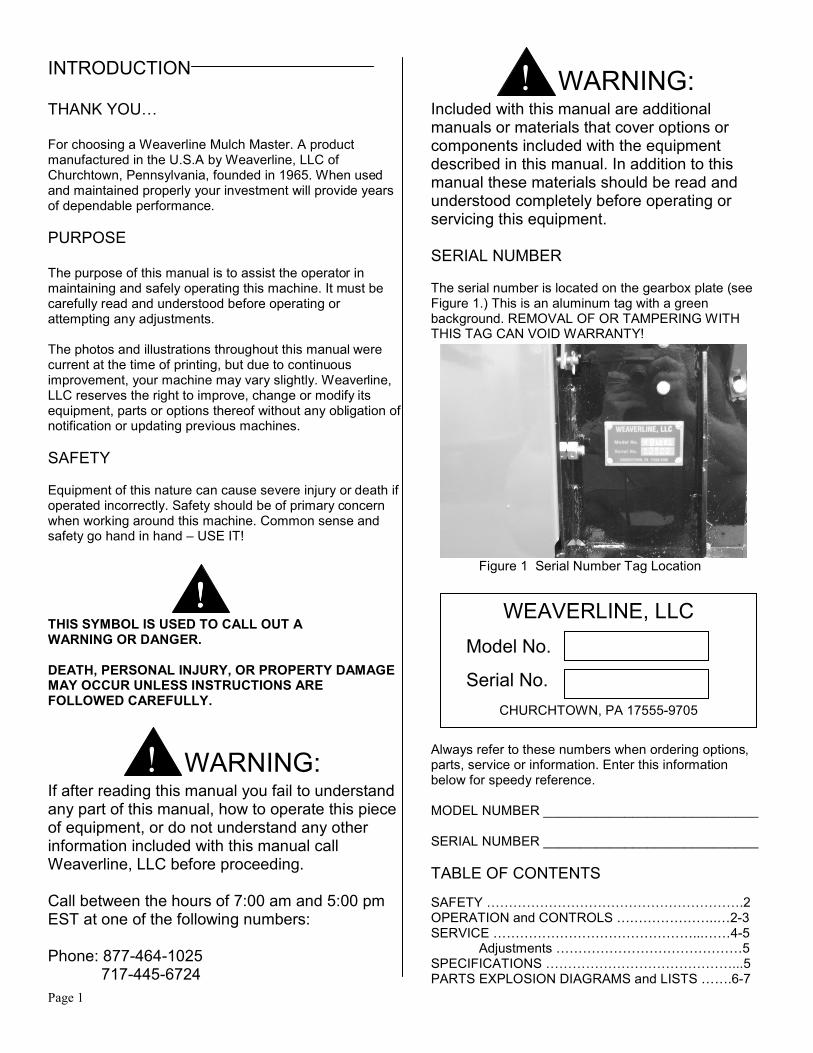
! WARNING: Included with this manual are additional manuals or materials that cover options or components included with the equipment described in this manual. In addition to this manual these materials should be read and understood completely before operating or servicing this equipment. SERIAL NUMBER The serial number is located on the gearbox plate (see Figure 1.) This is an aluminum tag with a green background. REMOVAL OF OR TAMPERING WITH THIS TAG CAN VOID WARRANTY!
Figure 1 Serial Number Tag Location Always refer to these numbers when ordering options, parts, service or information. Enter this information below for speedy reference. MODEL NUMBER _____________________________ SERIAL NUMBER _____________________________
TABLE OF CONTENTS
SAFETY ………………………………………………….2 OPERATION and CONTROLS …………………..…2-3 SERVICE ………………………………………...……4-5 Adjustments ……………………………………5 SPECIFICATIONS ……………………………………...5 PARTS EXPLOSION DIAGRAMS and LISTS …….6-7
WEAVERLINE, LLC
Model No.
Serial No.
CHURCHTOWN, PA 17555-9705
Page 2
SAFETY
! WARNING: This machine is to be operated only by adults.
Read and understand this operator’s manual
completely before attempting to operate,
service or make adjustments. Prior to use,
locate all warning decals and be aware of the
safety hazards they call out.
! WARNING: Never wear loose clothing while operating this
equipment, it can become caught in moving
parts.
! WARNING: Using materials other than those listed may
result in personal injury or damage to the
machine.
! WARNING: Hydraulic fluid escaping under pressure can
penetrate the skin. Hydraulic fluid may also
infect a minor cut or opening in the skin. If
injured by escaping fluid, seek medical
attention immediately. Relive all pressure
before disconnecting lines or servicing.
Your WEAVERLINE CHOPPER or MULCHER is
designed to process only certain materials. We suggest
only the following dry materials to be processed:
Straw
Prairie Grass
Compressed hay
Marsh Hay
Hay
Grass
Leaves
Paper*
Cardboard*
* Only when equipped with 76 knives.
Note: If bales are bound by wire instead of string or
plastic, remove wire before placing the bales into the
hopper.
PRE-OPERATION SAFETY CHECK
After going through the checklist above and the operator
is sure the machine is operating properly, chopping may
begin.
OPERATION
! CAUTION: On models equipped with a gas engine the
muffler and the exhaust manifold become very
hot during operation and remain hot for a
period of time after stopping the engine. Be
careful not to touch these items while they are
hot. To avoid severe burns or fire hazards, let
the engine cool before transporting or storing
this piece of equipment.
! WARNING: Never operate this piece of equipment without
the spout supplied with this machine securely
fastened to the blower housing. Never put any
part of your body or allow anyone else to put
any part of their body in front of either the
spout outlet or the hose outlet if so equipped.
AGAIN, be sure to read this manual completely
before operating or servicing this piece of equipment!
Keep all shields in place and carefully follow decal
instructions.
Make sure all electrical connections are secure and in
good condition. High voltage arcing can KILL.
Make sure all controls operate correctly.
Be sure that fire extinguisher is in place and fully
charged.
Check hopper for foreign objects before applying
power.
Keep others away. Make sure only the operator is
near the machine during operation.
Make sure all connections are tight and hoses in good
condition before applying pressure to the hydraulic
system.
After servicing, be sure to remove all tools and loose
objects from the machine.
Apply power to rotor and hopper. Check for
excessive noise and vibration.

Page 3
CONTROLS
Figure 2 Rotor Clutch Engagement
Figure 3 Hopper Rotation Clutch
Figure 4 Adjustable Grate
To begin operation:
1. Make sure all hopper and rotor engaging mechanisms are disengaged.
2. Set grate to highest position (Figure 4.)
3. Adjust discharge to desired position.
4. Start the engine on gas powered models.
5. Turn on the electric motor, apply power on the hydraulic unit or engage the rotor clutch on gas powered models (Figure 2.)
6. Place the first bale or other material to be chopped into the hopper.
Note: Cut and remove strings from bale immediately after inserting into hopper. Any sting or wire should be removed from other bundled materials before inserting into hopper.
7. Engage the clutch to start the hopper rotating (Figure 3)
8. Lower the grate so that the machine operates smoothly and produces desired length of cut.
Note: Moving the grate lever to the right will lower the grate and moving the lever to the left will raise the grate (Figure 4.) Adjusting the grate to a lower position decreases cutting time while increasing material length.
9. Continue to add bales (or other material) when the hopper is 1/2 to 2/3 empty.
DURING OPERATION
To stop operation:
1. Set grate to highest position.
2. Stop hopper rotation.
3. Slowly reduce engine speed to idle.
4. Disengage rotor and or shut off power supply.
For maintenance purposes and to reduce fire hazard, clean chopped material and debris from machine immediately after each use. On machines equipped with gasoline engines the fuel shut-off valve should be closed between uses.
Always wear approved eye protection.
Do not attempt to remove any material or
obstructions from hopper or rotor while machine is
running.
Never force materials onto the rotor with your hands,
feet or other objects.
Never stand in front of discharge.
Keep hands, feet, and clothing away from moving
parts.
Keep all shields and guards in place.
Carefully follow decal instructions (Replace decals
when badly worn or difficult to read.)
Do not open any covers or remove any shields while
rotor or hopper is rotating (Rotor continues to rotate
momentarily after power has been shut off.)

Page 4
SERVICE
! WARNING: Lockout power source and be sure all moving parts have come to rest before performing any service work. CLEANING Keeping the machine clean is an important part of maintenance and will help to insure proper operation. In addition to general cleaning, the rotor and engine (where applicable) should receive special attention. ROTOR An accumulation of materials such as baler twine or string around the rotor can result in poor operation or possibly even rotor or bearing failure. Any such buildup should be checked for and corrected prior to each use and more often if necessary. Burning is not a method that should be used to remove materials from the rotor. GAS ENGINE Chopping paper, straw, hay or other materials can create large amounts of dust. This makes it necessary to clean the air filtering system more frequently than recommended by the engine manufacturer. It is best to check the filter system prior to each use but at least once a week when using the chopper on a daily basis. Refer to engine manual for cleaning instructions. Allowing dust and debris to accumulate between cooling fins will cause an increase in operating temperature. As a result engine may suffer a loss of power and increase the possibility of fire. A clean engine will last longer and deliver peak performance. Follow the engine manufacturer’s instructions for additional maintenance procedures. GEAR BOX See manufacturer’s instructions. BEARINGS The bearings are sealed and require no lubrication. Build up of chopped material or other debris should be removed often to aid in preventing premature bearing failure. If you do choose to grease the rotor bearings, you should grease a maximum of one pump of a grease gun once every six months.
ROTOR BLADE REPLACEMENT. Refer to separate instructions included with this manual.
Adjustments GRATE STOP ADJUSTMENT If any knife tips are striking the end rod on the adjustable grate while in its lowest position the stops (two) must be adjusted. There should be a minimum of 1/16” (2 mm) between the grate end rod and all knife tips. (see Figure 5) The stop bolts are located on the back side of the rotor chamber and can be reached from under the machine (Figure 6)
Figure 5 Grate Adjustment
Figure 6 Adjustable Grate Stops
Page 5
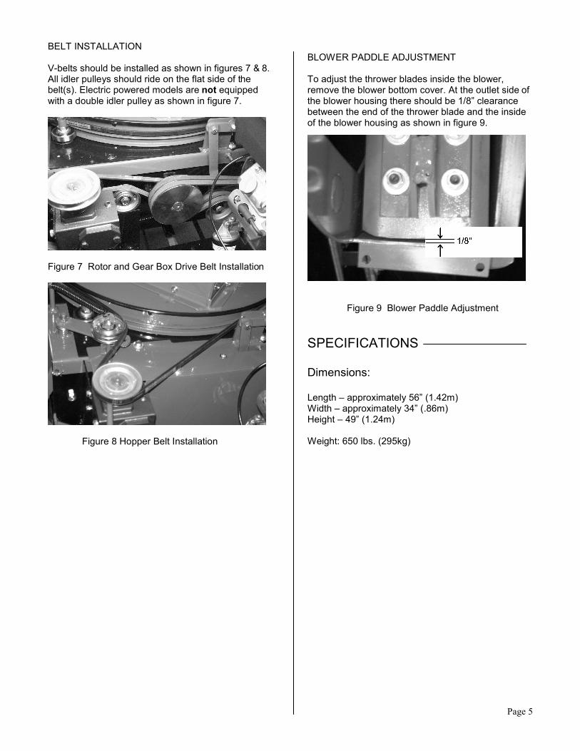
BELT INSTALLATION V-belts should be installed as shown in figures 7 & 8. All idler pulleys should ride on the flat side of the belt(s). Electric powered models are not equipped with a double idler pulley as shown in figure 7.
Figure 7 Rotor and Gear Box Drive Belt Installation
Figure 8 Hopper Belt Installation
BLOWER PADDLE ADJUSTMENT To adjust the thrower blades inside the blower, remove the blower bottom cover. At the outlet side of the blower housing there should be 1/8” clearance between the end of the thrower blade and the inside of the blower housing as shown in figure 9.
Figure 9 Blower Paddle Adjustment
SPECIFICATIONS Dimensions: Length – approximately 56” (1.42m) Width – approximately 34” (.86m) Height – 49” (1.24m) Weight: 650 lbs. (295kg)
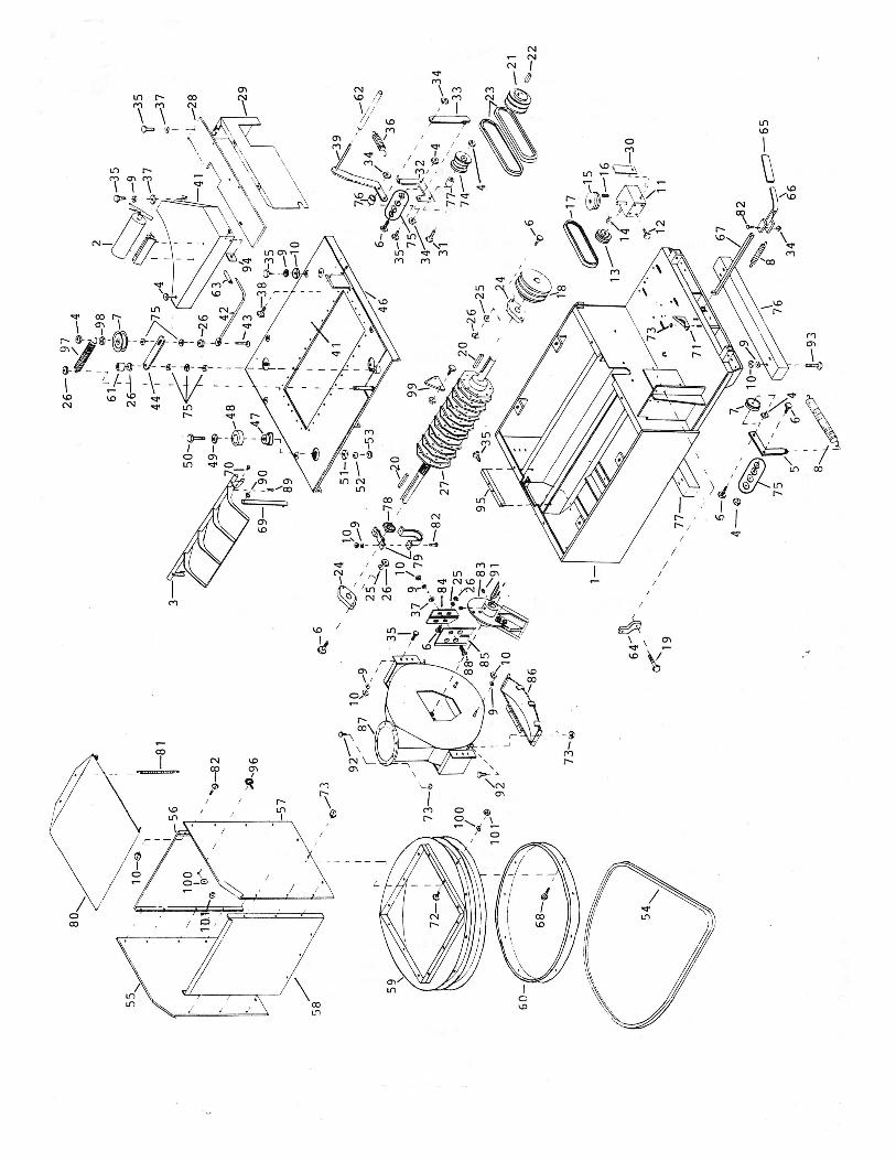
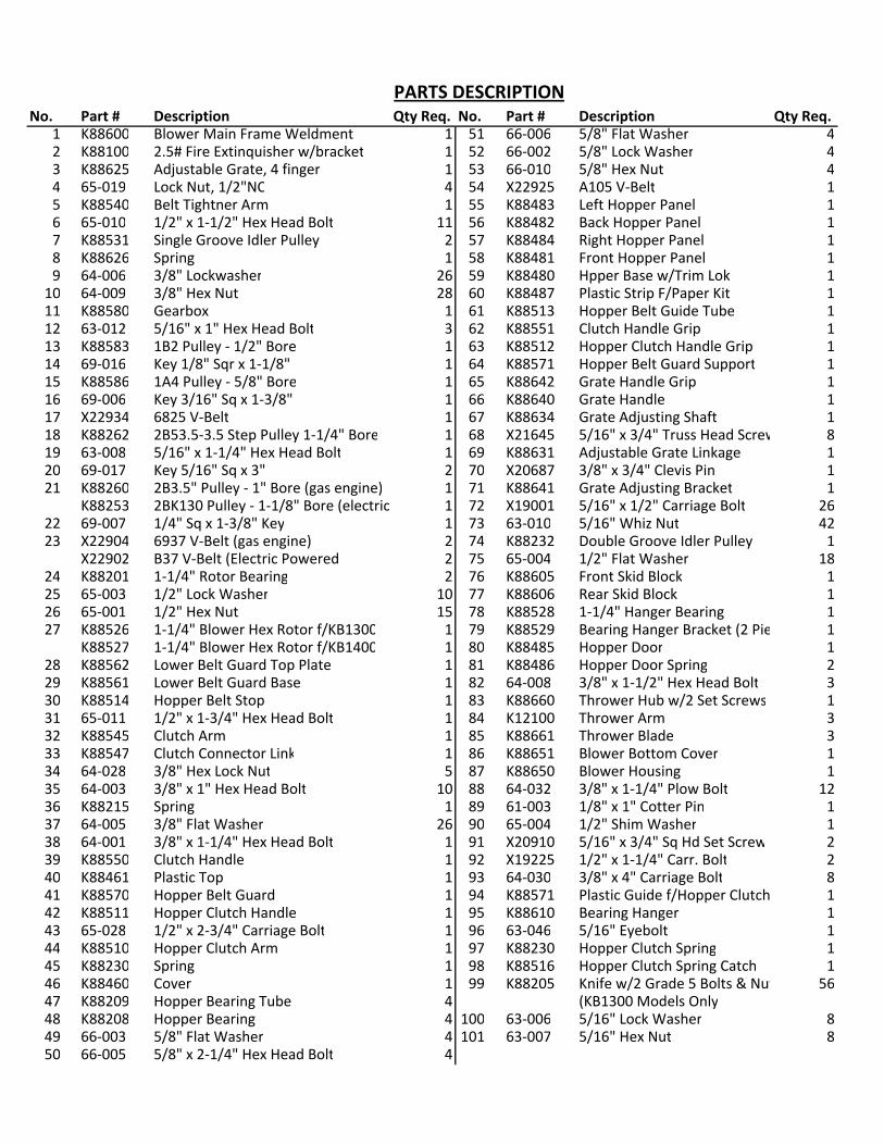
PARTS DESCRIPTION
No. Part # Description Qty Req. No. Part # Description Qty Req.
1 K88600 Blower Main Frame Weldment 1 51 66-006 5/8" Flat Washer 42 K88100 2.5# Fire Extinquisher w/bracket 1 52 66-002 5/8" Lock Washer 43 K88625 Adjustable Grate, 4 finger 1 53 66-010 5/8" Hex Nut 44 65-019 Lock Nut, 1/2"NC 4 54 X22925 A105 V-Belt 15 K88540 Belt Tightner Arm 1 55 K88483 Left Hopper Panel 16 65-010 1/2" x 1-1/2" Hex Head Bolt 11 56 K88482 Back Hopper Panel 17 K88531 Single Groove Idler Pulley 2 57 K88484 Right Hopper Panel 18 K88626 Spring 1 58 K88481 Front Hopper Panel 19 64-006 3/8" Lockwasher 26 59 K88480 Hpper Base w/Trim Lok 1
10 64-009 3/8" Hex Nut 28 60 K88487 Plastic Strip F/Paper Kit 111 K88580 Gearbox 1 61 K88513 Hopper Belt Guide Tube 112 63-012 5/16" x 1" Hex Head Bolt 3 62 K88551 Clutch Handle Grip 113 K88583 1B2 Pulley - 1/2" Bore 1 63 K88512 Hopper Clutch Handle Grip 114 69-016 Key 1/8" Sqr x 1-1/8" 1 64 K88571 Hopper Belt Guard Support 115 K88586 1A4 Pulley - 5/8" Bore 1 65 K88642 Grate Handle Grip 116 69-006 Key 3/16" Sq x 1-3/8" 1 66 K88640 Grate Handle 117 X22934 6825 V-Belt 1 67 K88634 Grate Adjusting Shaft 118 K88262 2B53.5-3.5 Step Pulley 1-1/4" Bore 1 68 X21645 5/16" x 3/4" Truss Head Screw 819 63-008 5/16" x 1-1/4" Hex Head Bolt 1 69 K88631 Adjustable Grate Linkage 120 69-017 Key 5/16" Sq x 3" 2 70 X20687 3/8" x 3/4" Clevis Pin 121 K88260 2B3.5" Pulley - 1" Bore (gas engine) 1 71 K88641 Grate Adjusting Bracket 1
K88253 2BK130 Pulley - 1-1/8" Bore (electric) 1 72 X19001 5/16" x 1/2" Carriage Bolt 2622 69-007 1/4" Sq x 1-3/8" Key 1 73 63-010 5/16" Whiz Nut 4223 X22904 6937 V-Belt (gas engine) 2 74 K88232 Double Groove Idler Pulley 1
X22902 B37 V-Belt (Electric Powered 2 75 65-004 1/2" Flat Washer 1824 K88201 1-1/4" Rotor Bearing 2 76 K88605 Front Skid Block 125 65-003 1/2" Lock Washer 10 77 K88606 Rear Skid Block 126 65-001 1/2" Hex Nut 15 78 K88528 1-1/4" Hanger Bearing 127 K88526 1-1/4" Blower Hex Rotor f/KB1300 1 79 K88529 Bearing Hanger Bracket (2 Pieces) 1
K88527 1-1/4" Blower Hex Rotor f/KB1400 1 80 K88485 Hopper Door 128 K88562 Lower Belt Guard Top Plate 1 81 K88486 Hopper Door Spring 229 K88561 Lower Belt Guard Base 1 82 64-008 3/8" x 1-1/2" Hex Head Bolt 330 K88514 Hopper Belt Stop 1 83 K88660 Thrower Hub w/2 Set Screws 131 65-011 1/2" x 1-3/4" Hex Head Bolt 1 84 K12100 Thrower Arm 332 K88545 Clutch Arm 1 85 K88661 Thrower Blade 333 K88547 Clutch Connector Link 1 86 K88651 Blower Bottom Cover 134 64-028 3/8" Hex Lock Nut 5 87 K88650 Blower Housing 135 64-003 3/8" x 1" Hex Head Bolt 10 88 64-032 3/8" x 1-1/4" Plow Bolt 1236 K88215 Spring 1 89 61-003 1/8" x 1" Cotter Pin 137 64-005 3/8" Flat Washer 26 90 65-004 1/2" Shim Washer 138 64-001 3/8" x 1-1/4" Hex Head Bolt 1 91 X20910 5/16" x 3/4" Sq Hd Set Screw 239 K88550 Clutch Handle 1 92 X19225 1/2" x 1-1/4" Carr. Bolt 240 K88461 Plastic Top 1 93 64-030 3/8" x 4" Carriage Bolt 841 K88570 Hopper Belt Guard 1 94 K88571 Plastic Guide f/Hopper Clutch Handle 142 K88511 Hopper Clutch Handle 1 95 K88610 Bearing Hanger 143 65-028 1/2" x 2-3/4" Carriage Bolt 1 96 63-046 5/16" Eyebolt 144 K88510 Hopper Clutch Arm 1 97 K88230 Hopper Clutch Spring 145 K88230 Spring 1 98 K88516 Hopper Clutch Spring Catch 146 K88460 Cover 1 99 K88205 Knife w/2 Grade 5 Bolts & Nuts 5647 K88209 Hopper Bearing Tube 4 (KB1300 Models Only48 K88208 Hopper Bearing 4 100 63-006 5/16" Lock Washer 849 66-003 5/8" Flat Washer 4 101 63-007 5/16" Hex Nut 850 66-005 5/8" x 2-1/4" Hex Head Bolt 4