Choosing the Right Tire - ASABE Technical Information...
9
This is not a peer-reviewed article. K. N. Brodbeck, 2004. Choosing the Right Tire: ASAE Distinguished Lecture # 28, pp. 1-13. Agricultural Equipment Technology Conference, 8-10 February 2004, Louisville, Kentucky USA. ASAE Publication Number 913C0204. Choosing the Right Tire Kenneth N. Brodbeck Manager, OE/Export Sales Engineering, Firestone Agricultural Tire Division, Des Moines, Iowa 50313 phone: 515-242-2308; e-mail: [email protected] Abstract. This lecture provides a short history of agricultural tractors and wheel equipment. A list of basic tire terms used to describe the tire profile is covered, along with performance criteria used to match mechanical front drive axles to the rear axle for proper gearing. In addition, the RCI table is introduced to provide a visual example of how tires can be grouped by rolling circumference and overall diameter. A description of tire size designations is listed for bias, radial, and flotation sizing. The load rating designations for ply, star, and load index is also ex- plained. The five most common tread designs for powered axles are defined, with examples of the different patterns. Two examples of the creation of new tire sizes are given: one for large, high-horsepower, four-wheel drive tractors, and one for high-capacity row crop sprayers. Cyclical loads and their restrictions are also discussed. Keywords. Aspect ratio, Cyclical loading, Load index, Load rating, Overall diameter, Rolling circumference, Rolling circumference index, Section height, Section width, Star rating, Static loaded ratio, Tread designations. Pneumatic tires have greatly improved the perform- ance of agricultural machines since their first introduc- tion in the 1930s. Tread designs, sizes, and uses con- tinue to evolve with the ever-increasing size, weight, speed, and complexity of today's machines. These pa- rameters continually challenge the tire company's ability to meet the needs of its customers. Tire and Tractor History Farmers relied on horse-drawn equipment for their workload for many years. Heavier tasks were next taken over by steam-powered tractors, with some machines exceeding 150 hp and weighing over 25 tons. Steam tractors, with steel wheels with bolt-on or cast cleats, can develop high drawbar loads but have several limita- tions: • They cannot be run on paved roads. • Their ride is extremely rough. • They cause high soil compaction. • They have limited mobility in wet soils. In the early 1920s, machinery companies began to manufacture tractors with internal combustion engines, but these tractors still had steel wheels and the same drawbacks for traction and mobility as steam tractors. For increased maneuverability in their orchards, Florida citrus farmers began using Goodyear aircraft tires on their orchard tractors in 1931 (Goodyear, 2003a). In 1934, a model WC Allis-Chalmers was the first tractor to be tested with pneumatic Firestone tires at the Nebraska Tractor Test lab. The lab conducted a 4-hour economy test with both steel wheels and pneumatic tires. The steel wheels produced 5.62 horsepower hours/ gal- lon. The rubber tires developed 8.18 horsepower hours/ gallon, a 45% fuel economy advantage over steel wheels. This is even more impressive when one realizes that both tests were conducted on soil (Wendel, 1985). In the early 1930s, tire companies began to offer pneumatic tires for farm tractors. By 1939, 85% of the original equipment manufacturers (OEMs) tractors came with rubber tires rather than steel (Lief, 1951). The ear- lier aircraft tires evolved into 45° bar bias-ply tires and into today's modern radial designs. Tire Terminology Refer to figures 1 and 2 for illustration of the following terms: • Section height is the design height of a tire section measured from the base of the tire bead to the top of the tread. • Section width is the width of a new tire, including 24- hour inflation growth and normal sidewalls, but not including protective side ribs, bars, or decorations. • Aspect ratio is the section height divided by section width, and is measured as a percentage. • Static loaded radius (SLR) is the dimension measured from the axle centerline to the ground when the tire is under load. SLR is usually specified at the tire's maximum load and inflation for that particular tire. • Overall diameter is twice the section height of a new tire, including 24-hour inflation growth, plus the nominal rim diameter. Rolling circumference (RC) is the distance traveled in one revolution of the tire under maximum load and inflation for that particular tire on a level, paved surface (for a measurement method, refer to ISO, 1997). The rolling circumference index (RCI) system is based on a
Transcript of Choosing the Right Tire - ASABE Technical Information...

This is not a peer-reviewed article. K. N. Brodbeck, 2004. Choosing the Right Tire: ASAE Distinguished Lecture # 28, pp. 1-13.
Agricultural Equipment Technology Conference, 8-10 February 2004, Louisville, Kentucky USA. ASAE Publication Number 913C0204.
Choosing the Right Tire
Kenneth N. Brodbeck Manager, OE/Export Sales Engineering, Firestone Agricultural Tire Division, Des Moines, Iowa 50313
phone: 515-242-2308; e-mail: [email protected]
Abstract. This lecture provides a short history of agricultural tractors and wheel equipment. A list of basic tire terms used to describe the tire profile is covered, along with performance criteria used to match mechanical front drive axles to the rear axle for proper gearing. In addition, the RCI table is introduced to provide a visual example of how tires can be grouped by rolling circumference and overall diameter. A description of tire size designations is listed for bias, radial, and flotation sizing. The load rating designations for ply, star, and load index is also ex-plained. The five most common tread designs for powered axles are defined, with examples of the different patterns. Two examples of the creation of new tire sizes are given: one for large, high-horsepower, four-wheel drive tractors, and one for high-capacity row crop sprayers. Cyclical loads and their restrictions are also discussed.
Keywords. Aspect ratio, Cyclical loading, Load index, Load rating, Overall diameter, Rolling circumference, Rolling circumference index, Section height, Section width, Star rating, Static loaded ratio, Tread designations.
Pneumatic tires have greatly improved the perform-ance of agricultural machines since their first introduc-tion in the 1930s. Tread designs, sizes, and uses con-tinue to evolve with the ever-increasing size, weight, speed, and complexity of today's machines. These pa-rameters continually challenge the tire company's ability to meet the needs of its customers.
Tire and Tractor History Farmers relied on horse-drawn equipment for their
workload for many years. Heavier tasks were next taken over by steam-powered tractors, with some machines exceeding 150 hp and weighing over 25 tons. Steam tractors, with steel wheels with bolt-on or cast cleats, can develop high drawbar loads but have several limita-tions: • They cannot be run on paved roads. • Their ride is extremely rough. • They cause high soil compaction. • They have limited mobility in wet soils.
In the early 1920s, machinery companies began to manufacture tractors with internal combustion engines, but these tractors still had steel wheels and the same drawbacks for traction and mobility as steam tractors. For increased maneuverability in their orchards, Florida citrus farmers began using Goodyear aircraft tires on their orchard tractors in 1931 (Goodyear, 2003a).
In 1934, a model WC Allis-Chalmers was the first tractor to be tested with pneumatic Firestone tires at the Nebraska Tractor Test lab. The lab conducted a 4-hour economy test with both steel wheels and pneumatic tires. The steel wheels produced 5.62 horsepower hours/ gal-lon. The rubber tires developed 8.18 horsepower hours/
gallon, a 45% fuel economy advantage over steel wheels. This is even more impressive when one realizes that both tests were conducted on soil (Wendel, 1985).
In the early 1930s, tire companies began to offer pneumatic tires for farm tractors. By 1939, 85% of the original equipment manufacturers (OEMs) tractors came with rubber tires rather than steel (Lief, 1951). The ear-lier aircraft tires evolved into 45° bar bias-ply tires and into today's modern radial designs.
Tire Terminology Refer to figures 1 and 2 for illustration of the
following terms: • Section height is the design height of a tire section
measured from the base of the tire bead to the top of the tread.
• Section width is the width of a new tire, including 24-hour inflation growth and normal sidewalls, but not including protective side ribs, bars, or decorations.
• Aspect ratio is the section height divided by section width, and is measured as a percentage.
• Static loaded radius (SLR) is the dimension measured from the axle centerline to the ground when the tire is under load. SLR is usually specified at the tire's maximum load and inflation for that particular tire.
• Overall diameter is twice the section height of a new tire, including 24-hour inflation growth, plus the nominal rim diameter. Rolling circumference (RC) is the distance traveled
in one revolution of the tire under maximum load and inflation for that particular tire on a level, paved surface (for a measurement method, refer to ISO, 1997). The rolling circumference index (RCI) system is based on a

Figure 1. Tire terminology. Figure 2. Tractor tire, unloaded and loaded.
geometric progression in which each indexed rolling circumference is a constant proportion to the rolling circumferences above and below it (for the calculation method, refer to Tire and Rim Association, 1997). Table 1 lists RCI and RC values for agricultural tires.
Radial tire, metric size is indicated as 480/80R46 155A8 (fig. 3): 480 = tire section width in mm 80 = aspect ratio as a percentage R = radial construction
Cyclical loading means the tire load cycles between the maximum allowable load and the transport load. Unloading must occur before road transport. Maximum load may not be carried for more than one mile before unloading operations begins (refer to the appropriate cyclic load and inflation tables; Tire and Rim Associa-tion, 2003a).
46 = rim diameter in inches 155 = load index value (fig. 4 and table 2) A8 = refers to a speed of 25 mph (40 km/h).
Bias-ply tire, size is indicated as 18.4-38 (10): 18.4 = tire section width in inches - = denotes bias ply 38 = rim diameter in inches
Example Tire Construction Designations
(10) = ply rating, not the actual number of plies.
Flotation bias-ply tire, size is indicated as 76×50.00B32 standard, or 1250/45B32 metric (fig. 5): Radial tire, standard size is indicated as 18.4R46 (3*)
(fig. 3): 76 = tire design diameter in inches 50.00 = tire section width in inches 18.4 = tire section width in inches. B = denotes the tire has tread plies in the crown of R = radial construction the tire 46 = rim diameter in inches 32 = rim diameter in inches. (3*) = load designation per load and inflation tables
5-(14-16) (Tire and Rim Association, 2003a).
Figure 4. Load index and speed symbol.
Figure 3. Standard and metric size designation.
6

Tab
le 1
. Rol
ling
circ
umfe
renc
e tir
e fa
mili
es.[a
]
Min
imum
Rec
omm
ende
d R
ow W
idth
[e]
RC
I[b]
Gro
up
RC
[c]
(in.)
OD
[d]
(in.,
appr
ox.)
18
20
22
26
30
32
40+
Non
-Row
Cro
p
Sect
ion
Wid
th -
Rea
r Tire
s H
arve
ster
Fl
otat
ion
290
(11.
2)
320
(12.
4)
380
(14.
9)
420
(16.
9)
480
(18.
4)
520
(20.
8)
620
(24.
5)
710
(28.
0)
800-
900
(30.
5-35
.5)
1000
+ (4
0+)
48
243
8138
0/10
5R50
380/
90R
54
48
0/80
R50
520/
85R
4665
0/85
R38
710/
70R
4280
0/70
R38
900/
65R
32
47
23
077
320/
90R
54(1
2.4R
54)
380/
90R
5048
0/80
R46
(18.
4R46
) 52
0/85
R42
(2
0.8R
42)
620/
70R
4271
0/70
R38
710/
75R
34
900/
50R
42
900/
60R
32
76×5
0-32
78×4
5-32
46
21
973
320/
90R
5038
0/90
R46
(14.
9R46
) 42
0/80
R46
480/
80R
42(1
8.4R
42)
520/
85R
38
(20.
8R38
) 65
0/65
R38
VA
73×4
4-32
45
20
769
320/
90R
46
480/
80R
38(1
8.4R
38)
(20.
8R34
)65
0/75
R32
(24.
5R32
) (2
3.1R
34)
600/
65R
38
800/
65R
32
68×5
0.00
-32
(30.
5LR
32)
67×3
4.00
-25
Se
ctio
n W
idth
- Fr
ont T
ires
Har
vest
er
Flot
atio
n 23
0(9
.0-9
.5)
290
(11.
0-11
.2)
320
(12.
4)
380
(14.
9)
420
(16.
5 or
16.
9)
480
(18.
4)
520
(20.
8)
620
(23.
1 or
24.
5)
800
(30.
5)
1000
+ (4
0+)
44
197
6523
0/95
R48
38
0/80
R42
420/
85R
38(1
6.9R
38)
480/
85R
34
(18.
4R34
) 54
0/65
R38
620/
75R
30(2
3.1-
30)
1050
/50R
2566×4
3-25
66×4
4-25
43
18
763
320/
90R
42(1
2.4-
42)
380/
80R
3842
0/85
R34
480/
70R
3454
0/65
R34
600/
70R
30(2
3.1-
26)
42
17
759
320/
85R
38(1
2.4-
38)
380/
85R
34
(14.
9R34
) 42
0/90
R30
(1
6.9R
30)
480/
70R
30
(18.
4-30
) 54
0/65
R30
600/
65R
2858×3
1.00
-26
41
16
856
290/
95R
3432
0/85
R34
380/
85R
30(1
4.9R
30)
420/
85R
28
(16.
9R28
) 48
0/70
R28
(1
8.4R
26)
540/
65R
2880
0/50
-25
54×3
1.00
-25
40
160
5338
0/85
R28
(14.
9R28
) 42
0/85
R26
(1
6.9R
26)
480/
65R
2854
0/65
R24
39
152
50.5
340/
85R
28(1
3.6R
28)
(14.
9R26
)(1
6.9R
24)
480/
65R
2448×2
5.00
-20
48×3
1.00
-20
[a]
Tire
size
s are
list
ed in
met
ric (a
nd st
anda
rd) d
imen
sion
s:
A
ll si
zes i
n th
e sa
me
row
are
app
roxi
mat
ely
the
sam
e ou
tsid
e di
amet
er.
A
ll si
zes i
n th
e sa
me
colu
mn
are
appr
oxim
atel
y th
e sa
me
wid
th.
Fo
r spe
cific
app
licat
ions
, con
sult
OEM
dat
a bo
oks f
or a
ctua
l dim
ensi
ons.
[b]
RC
I = ro
lling
circ
umfe
renc
e in
dex;
indi
cate
s fam
ily o
f tire
s with
sim
ilar r
ollin
g ci
rcum
fere
nces
(Tire
and
Rim
Ass
ocia
tion,
199
7).
[c]
RC
= ro
lling
circ
umfe
renc
e (I
SO, 1
997)
. [d
] O
D =
ove
rall
diam
eter
, the
app
roxi
mat
e he
ight
of t
he ti
re in
inch
es.
[e]
The
min
imum
row
wid
th in
whi
ch th
e op
erat
or c
an c
omfo
rtabl
y gu
ide
the
tire
betw
een
the
crop
row
s.

Load Ratings Table 2. International load index numbers, kilogram loads, and equivalent pound loads (Goodyear, 2003b, pp. 13).
In the past, bias-ply or cross-ply tires were rated by the actual number of plies used in the tire to carry the vertical load. A 6-ply tire had six actual plies and carried 2000 lbs. During and after Word War II, man-made ma-terials such as nylon, polyester, rayon, and steel become available for the tire body and are several times stronger than the original cotton body plies. Today, an 8-ply rated tire may have only six actual plies, but it carries an 8-ply load rating.
Load Index kg lbs
Load Index kg lbs
Load Index kg lbs
80 81 82 83 84 85 86 87 88 89
450 462 475 487 500 515 530 545 560 580
990 1020 1050 1070 1100 1140 1170 1200 1230 1280
120 121 122 123 124 125 126 127 128 129
1400 1450 1500 1550 1600 1650 1700 1750 1800 1850
3080 3200 3300 3420 3520 3640 3740 3860 3960 4080
160 161 162 163 164 165 166 167 168 169
4500 4625 4750 4875 5000 5150 5300 5450 5600 5800
9900 102001050010700110001140011700120001230012800
90 91 92 93 94 95 96 97 98 99
600 615 630 650 670 690 710 730 750 775
1320 1360 1390 1430 1480 1520 1570 1610 1650 1710
130 131 132 133 134 135 136 137 138 139
1900 1950 2000 2060 2120 2180 2240 2300 2360 2430
4180 4300 4400 4540 4680 4800 4940 5080 5200 5360
170 171 172 173 174 175 176 177 178 179
6000 6150 6300 6500 6700 6900 7100 7300 7500 7750
13200136001390014300148001520015700161001650017100
100 101 102 103 104 105 106 107 108 109
800 825 850 875 900 925 950 975
1000 1030
1760 1820 1870 1930 1980 2040 2090 2150 2200 2270
140 141 142 143 144 145 146 147 148 149
2500 2575 2650 2725 2800 2900 3000 3075 3150 3250
5520 5680 5840 6000 6150 6400 6600 6800 6950 7150
100 181 182 183 184 185 186 187 188 189
8000 8250 8500 8750 9000 9250 9500 9750
1000010300
17600182000870019300198002040020900215002200022700
110 111 112 113 114 115 116 117 118 119
1060 1090 1120 1150 1180 1215 1250 1285 1320 1360
2340 2400 2470 2540 2600 2680 2760 2830 2910 3000
150 151 152 153 154 155 156 157 158 159
3350 3450 3550 3650 3750 3875 4000 4125 4250 4375
7400 7600 7850 8050 8250 8550 8800 9100 9350 9650
190 191 192 193 194 195 196 197 198 199
10600109001120011500118001215012500128501320013600
23400240002470025400260002680027600283002910030000
Radial tires originally carried the same ply rating with equivalent loads and inflation pressures as the equivalent-size bias tire. In 1987, the Tire and Rim As-sociation increased the radial load by 7% over the equivalent-size bias tire. This change allowed radial tires to better utilize their radial construction for better trac-tion and load capabilities than bias tires.
At the same time, the Tire and Rim Association cre-ated a star rating system for radial tires to denote a maximum pressure for a given load rating. This elimi-nated the varied inflation pressures called for in the bias load tables (see bias load table example; Tire and Rim Association, 2003b). No matter what size of radial tire, all one-star tires' maximum inflation is 18 psi (fig. 6 and table 3). Each additional star rating requires an addi-tional 6 psi increase in inflation pressure (Tire and Rim Association, 2003b, pp. 5-12).
Figure 6. Radial star symbol per maximum inflation pressure.
Table 3. Radial star, service index, and ply rating comparison.
Tire Size Symbol Service Index
Ply Rating
20.8R42 * 149A8 10 ** 155A8 *** 159A8
23.1R34 * 151A8 8 ** 157A8 *** 161A8
24.5R32 * 154A8 10 ** 159A8 *** 164A8
30.5LR32 * 159A8 10, 12 ** 166A8 *** 170A8 Figure 5. Flotation size designation.
8

Figure 7. Bias-ply tire construction. Figure 8. Radial tire construction.
Bias Tire Construction Radial Tire Construction The carcass of a bias-ply tire consists of layers (or
plies) of fabric with cords that run diagonally from bead to bead at an angle called a bias angle (fig. 7). The cords of adjacent plies run in opposite directions, giving stability to the tire. The sidewalls of a bias tire are rela-tively stiff due to this criss-crossing of the body plies.
The body cords of a radial tire run parallel to each other from bead to bead at right angles to the tread cen-terline (fig. 8). Radial tires also have stabilizer plies (or belts) beneath the tread, with cords that run in a nearly circumferential direction (at a small angle to the tread center-line). Most of the flexing in the radial tire occurs in the sidewall area, while the tread area remains rela-tively stiff due to the belts.
The bias tire's relatively stiff sidewall offers advan-tages over the radial tire in certain applications, such as forestry, where the radial tire sidewall can be prone to cuts and punctures while working in a severe environ-ment.
Tread Designs for Powered Axles There are five principle drive tire tread designs: R1,
R1W, R2, R3, and R4 (fig. 9). Because of the criss-crossing of the body plies, the bias tire has more internal friction than the radial tire. This is one of the major reasons that bias tires have been replaced in many applications, the radial runs cooler and more efficiently. Depending on conditions, radial tires show an advantage of 6% to 14% in traction, fuel effi-ciency, and reduced wheel slippage over bias tires.
R1 tread is used for general farming and typically provides the best traction in most soil conditions. The tread is an aggressive pattern for developing traction in hard to soft soil conditions. The tread void area is ap-proximately 70% of the total footprint for good cleaning in wet soils and good penetration in firmer soils.
R1 R1W R2 R3 R4 Figure 9. Basic drive tire tread patterns.
9

R1W tread originated in Europe and has a 20% deeper skid depth than R1. European tractors often spend a higher percentage time on paved surfaces, and the deeper tread increases tire life. This tread depth is popular in Europe and is becoming more prominent in North American markets.
The RCI chart (table 1) lists sizes of tires with equivalent RCI values from the narrowest to the widest tires that are commercially available. The RCI groups in table 1 are listed by tire diameter, from largest to small-est, for high-horsepower row crop tractors. RCI groups 48 to 45 are considered rear-axle sizes, and RCI groups 44 to 39 are considered front-axle sizes. Obviously, smaller MFD tractors can utilize the chart, but the RCI indices need to be extended to incorporate the smaller front drive tire families.
R2 tread is used in wet farming applications where the machine must run through mud and standing water. Typical applications are rice, sugar cane, and high-value vegetable crops. The tread is twice as deep as the stan-dard R1 tread. While R2 looks extremely aggressive, the typical 45° bar angle is maximized for cleaning in wet soils and is not as efficient for developing traction as R1 in general farming conditions.
North American tractor manufacturers largely use a 5-step RCI difference between the front and rear axle. Any group 47 rear tire will match up with any group 42 front tire. For example:
R3 tread is a non-aggressive pattern where minimal ground disturbance is required, such as for airports, golf courses, cemeteries, roadside maintenance, dryland combining, and on large heavy trailers such as manure and grain carts. The tread typically has a relatively closed tread pattern to evenly distribute the load, with void area in the 30% range.
Rear = 18.4R46 RCI 47 Front = 14.9R34 or 16.9R30; both are RCI 42 tires. European tractor manufacturers often use a 4-step
difference. A 710/70R38 group 47 rear tire will match up with a 600/70R30 group 43 front tire. Basically, any row of rear sizes will match up with the corresponding row of front sizes because they are within the accepted range of RC values. R4 treads are for construction and light industrial
equipment such as backhoes and small end loaders. The tread depth is approximately 70% of the R1 tread and is designed for good wear on roads and reasonable traction on soils at a construction site. The tread-to-void ratio is typically 50/50.
Creating a New Low-Pressure Traction Tire
As equipment continues to increase in size, horsepower, and weight, tougher demands are made on tires. The tire industry was challenged to create a tire for a high-horsepower four-wheel drive tractor that would fulfill the following criteria:
Choosing the Right Tire for MFD Tractors
• Easily control power hop with higher load capacity without an increase in inflation pressure and keep soil compaction to a minimum (Wiley, 1992; Abu-Hamdeh, 1995a).
For many years, tractors were powered by a single drive axle; this is called a two-wheel drive tractor. Front wheel assist tractors became available in the 1960s and 1970s. They offered a hydraulically powered front axle with one or two field speeds for extra traction. In the 1960s through the 1980s, tractor manufacturers began to offer tractors with mechanically powered front axles, called mechanical front drive (or MFD) tractors. These tractors have a mechanical drive shaft that powers the front axle and allows the tractor to utilize the front axle in every gear of the tractor's transmission.
• Maximum overall diameter of approximately 206 cm (81 in.), RCI group 48, for current tractor chassis limits.
• Maximum width of 800 mm, so that the overall width on a 4WD tractor with dual tires is under 490 cm (16 ft).
• Minimum rim diameter of 38 inches to minimize the chance of rim slip and yet provide the largest air chamber within the tire to maximize load capacity.
Because the front and rear tires are of different di-ameters, matching the front and rear tires is important for proper gearing between the two axles. A desired overspeed on the front tire, relative to the rear, is in the range of 0% to 6%, depending on the tractor manufac-turer. Rolling circumference is the best dimension to work with in calculating the lead/lag of the two axles on an MFD tractor. In the past, tractor engineers, imple-ment manufacturers, and tire dealers had to work through these calculations to determine the proper front and rear tire sizes. Today, the tractor and tire industries have attempted to standardize new tires and tractors within the RCI chart (table 1).
Existing large rear sizes include the 710/70R42 tire in group 48 and a 900/50R42 tire in group 47. Neither tire adequately controls power hop on the larger 4WD trac-tors. Subtracting the 38 inch rim diameter from the 206 cm (81 in.) OD for RCI 48 leaves 109 cm (43 in.) of tire section height. Dividing the 109 cm (43 in.) by 2 leaves a single section height of 54.6 cm (21.5 in.). The aspect ratio is the section height divided by the section width. In this case, we have 54.6 cm (21.5 in.) divided by a maximum section width of 800 mm, for an aspect ratio of 68.2%. Rounding to 70% then describes the new size as an 800/70R38 173A8 at 160 kPa (23 psi) (fig. 10).
10

Table 4. Tire size, load index, load, and inflation pressure.
Load Inflation Tire Size
Load Index kg lbs kPa psi
380/90R54 152 3550 7850 240 35 380/90R54 168 5600 12,300 480 70 380/105R50 168 5600 12,300 440 64
In this case, the overall diameter and section width are fixed. The only remaining variables are the section height and rim diameter. Obviously, the largest air vol-ume will provide the largest load capacity at the lowest internal tire pressure. A lower tire pressure is desirable both for minimizing soil compaction and for minimizing stresses within the tire and wheel.
The existing tractor tire size that fits the diameter and width is the 380/90R54 152A8/B. However, the rated load is much lower than the required 5440 kg (12,000 lbs). The load and inflation for the tractor tire are 3550 kg at 200 kPa (35 psi). To reach the required load, the 380/90R54 requires 480 kPa (70 psi) (table 4).
Figure 10. 710/70R42 tires versus 800/70R38 tires.
The new size provides up to 6500 kg (14,300 lbs) of vertical load capacity at 160 kPa (23 psi) at 40 km/h (25 mph) for tractors. For cyclical work on combines, the tire will carry 11,100 kg (24,300 lbs) at 10 km/h (6 mph) at 200 kPa (29 psi).
A lower inflation pressure is desirable. Increasing the tire internal volume will require a larger aspect ratio and a correspondingly smaller rim. The approximate overall diameter for the 380/90R54 tire, or any metric marked tire, is calculated as: Creating a New High-Load
Narrow Tire OD = section width × aspect ratio + rim diameter In this case: The farming industry continues to move from me-
chanical weed control to liquid herbicides applied with high-capacity row crop sprayers. Again, faster speeds and larger payloads are demanded by the original equipment manufacturers. The machine requirements are as follows:
OD = (380 mm × 90% × 2 sections) + (54 in. rim diameter × 25.4 mm/in.) = 2,056 mm (80.9 in.)
This value is approximate because of tire growth tol-erances with inflation and usage. Agricultural rims, typi-cally, run in 4-inch graduations. The next smaller rim diameter is 50 inches in diameter and is commercially available. The aspect ratio required to meet the previ-ously listed criteria is calculated as:
• Operate a fully loaded sprayer at transport speed of 50 km/h (30 mph) within the Tire and Rim Association's load formula.
• Maximum overall diameter of approximately 206 cm (81 in.), RCI group 48, for maximum ground clearance and fit within the existing RCI group 48 family of tractor sizes. Aspect ratio = (overall diameter - rim diameter)
(section width × 2 sections) × 100% • Maximum width of 380 mm (14.9 in.) so that the
tires will negotiate 30 inch crop rows. In this case: • Minimum rim diameter of 46 inches to fit around
planned wheel accessories. Aspect ratio = (2056 mm - 50 in. × 25.4) (380 mm × 2) × 100%= 103.4
• Load per tire is just under 5440 kg (12,000 lbs). The smaller size most often used on existing ma-
chines is the 380/90R46 R1W. This tire will carry 3875 kg (8550 lbs) at 320 kPa (46 psi) and has an overall di-ameter of 182 cm (71.8 in.) in RCI group 46. However, the new sprayers require higher loads, and the tire must be able to operate on a continual basis at full load and not reduce sprayer performance due to heat concerns while running at 50 km/h (30 mph).
or 105%, when rounded to the closest value divisible by 5, which suggests the 380/105R50 tire (fig. 11).
What is a Cyclical Loaded Tire? Harvesting, spraying, and fertilizer work involve cy-
clical loaded tires. The load ratings for both bias-ply and radial tires for these operations reflect a different duty cycle when compared to agricultural tractors. Cyclic service ratings are intended for use on vehicles with minimal requirements for torque transmission and with
A portion of the Tire and Rim Association's load formula utilizes contained air volume and internal infla-tion pressure to calculate the maximum load for the tire.
11
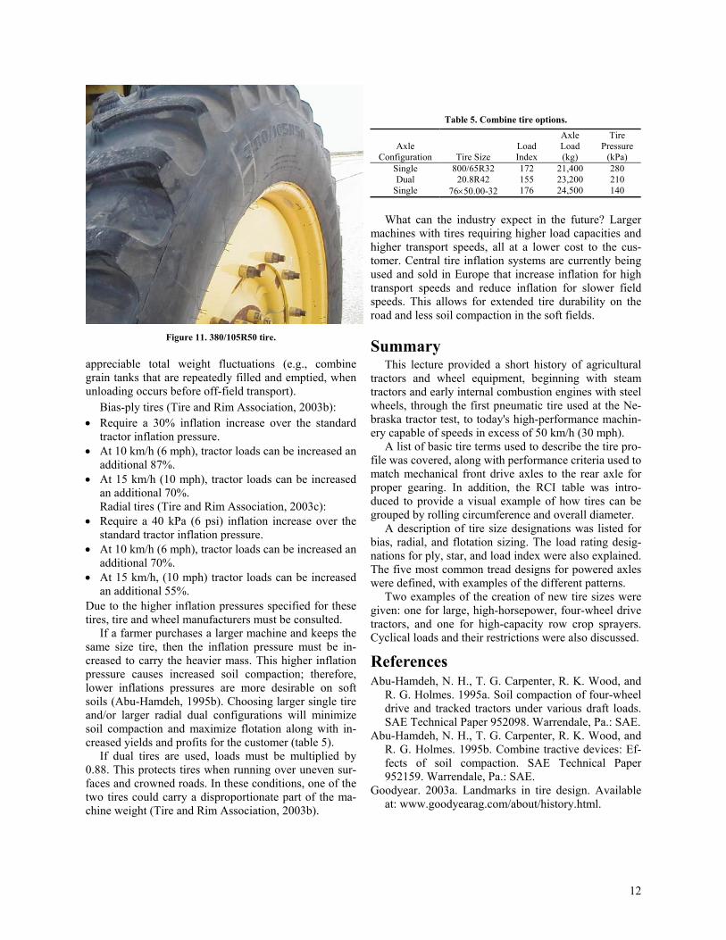
Table 5. Combine tire options.
Axle Configuration Tire Size
Load Index
Axle Load (kg)
Tire Pressure
(kPa) Single 800/65R32 172 21,400 280 Dual 20.8R42 155 23,200 210
Single 76×50.00-32 176 24,500 140
What can the industry expect in the future? Larger machines with tires requiring higher load capacities and higher transport speeds, all at a lower cost to the cus-tomer. Central tire inflation systems are currently being used and sold in Europe that increase inflation for high transport speeds and reduce inflation for slower field speeds. This allows for extended tire durability on the road and less soil compaction in the soft fields.
Figure 11. 380/105R50 tire. Summary
appreciable total weight fluctuations (e.g., combine grain tanks that are repeatedly filled and emptied, when unloading occurs before off-field transport).
This lecture provided a short history of agricultural tractors and wheel equipment, beginning with steam tractors and early internal combustion engines with steel wheels, through the first pneumatic tire used at the Ne-braska tractor test, to today's high-performance machin-ery capable of speeds in excess of 50 km/h (30 mph).
Bias-ply tires (Tire and Rim Association, 2003b): • Require a 30% inflation increase over the standard
tractor inflation pressure. A list of basic tire terms used to describe the tire pro-
file was covered, along with performance criteria used to match mechanical front drive axles to the rear axle for proper gearing. In addition, the RCI table was intro-duced to provide a visual example of how tires can be grouped by rolling circumference and overall diameter.
• At 10 km/h (6 mph), tractor loads can be increased an additional 87%.
• At 15 km/h (10 mph), tractor loads can be increased an additional 70%. Radial tires (Tire and Rim Association, 2003c):
• Require a 40 kPa (6 psi) inflation increase over the standard tractor inflation pressure. A description of tire size designations was listed for
bias, radial, and flotation sizing. The load rating desig-nations for ply, star, and load index were also explained. The five most common tread designs for powered axles were defined, with examples of the different patterns.
• At 10 km/h (6 mph), tractor loads can be increased an additional 70%.
• At 15 km/h, (10 mph) tractor loads can be increased an additional 55%. Two examples of the creation of new tire sizes were
given: one for large, high-horsepower, four-wheel drive tractors, and one for high-capacity row crop sprayers. Cyclical loads and their restrictions were also discussed.
Due to the higher inflation pressures specified for these tires, tire and wheel manufacturers must be consulted.
If a farmer purchases a larger machine and keeps the same size tire, then the inflation pressure must be in-creased to carry the heavier mass. This higher inflation pressure causes increased soil compaction; therefore, lower inflations pressures are more desirable on soft soils (Abu-Hamdeh, 1995b). Choosing larger single tire and/or larger radial dual configurations will minimize soil compaction and maximize flotation along with in-creased yields and profits for the customer (table 5).
References Abu-Hamdeh, N. H., T. G. Carpenter, R. K. Wood, and
R. G. Holmes. 1995a. Soil compaction of four-wheel drive and tracked tractors under various draft loads. SAE Technical Paper 952098. Warrendale, Pa.: SAE.
Abu-Hamdeh, N. H., T. G. Carpenter, R. K. Wood, and R. G. Holmes. 1995b. Combine tractive devices: Ef-fects of soil compaction. SAE Technical Paper 952159. Warrendale, Pa.: SAE.
If dual tires are used, loads must be multiplied by 0.88. This protects tires when running over uneven sur-faces and crowned roads. In these conditions, one of the two tires could carry a disproportionate part of the ma-chine weight (Tire and Rim Association, 2003b).
Goodyear. 2003a. Landmarks in tire design. Available at: www.goodyearag.com/about/history.html.
12
Goodyear. 2003b. Farm tire handbook. Available at: www.goodyearag.com/img/tires/farmFarmHndbk_1.pdf.
Tire and Rim Association. 2003b. Bias cyclic loads. In Engineering Design Information, section 5-26 to 5-27. Copley, Ohio: Tire and Rim Association. ISO. 1997. ISO 11795: Agricultural tractor drive wheel
tires—Method of measuring tire rolling circumfer-ence. Geneva, Switzerland: ISO.
Tire and Rim Association. 2003c. Radial cyclic loads. In Engineering Design Information, section 5-28. Cop-ley, Ohio: Tire and Rim Association. Lief, A. 1951. The Firestone Story. New York, N.Y.:
Whittlesey House, a McGraw-Hill Company. Wendel, C. H. 1985. Test No. 223. In Nebraska Tractor Tests Since 1920. St. Paul, Minn.: Motorbooks Inter-national.
Tire and Rim Association. 1997. Engineering Design Information, section 5-20. Copley, Ohio: Tire and Rim Association. Wiley, J.C., B. E. Romig, L. V. Anderson, and F. M.
Zoz. 1992. Optimizing dynamic stability and per-formance of tractors with radial tires. ASAE Paper No. 921586. St. Joseph, Mich.: ASAE.
Tire and Rim Association. 2003a. Cyclic load and infla-tion tables. In Engineering Design Information, sec-tion 5-26 to 5-29. Copley, Ohio: Tire and Rim Asso-ciation.
13