Choose the Gas That’s Right for the Cutting
8
CHOOSE T HE GAS T HAT’S R IGHT F OR T HE CUTT ING OPER ATION Jim Donaghy Praxair, In c. Welding Applications Consultant Reprinted from Welding Journal De ce mb er 19 95
Transcript of Choose the Gas That’s Right for the Cutting

7/28/2019 Choose the Gas That’s Right for the Cutting
http://slidepdf.com/reader/full/choose-the-gas-thats-right-for-the-cutting 1/8
CHOOSE THE GAS
THAT’S RIGHT FOR THE
CUTTING OPERATION
Jim Donaghy
Praxair, Inc.
Welding Applications Consultant
Reprinted from
Welding Journal
December 1995

7/28/2019 Choose the Gas That’s Right for the Cutting
http://slidepdf.com/reader/full/choose-the-gas-thats-right-for-the-cutting 2/8
ach cutting process has its own uni-que characteristics and require-
ments. One of the major requirementsof a cutting operation is selecting theproper gas or gas mixture for the processbeing used. To help make that selection,three major cutting processes and thegases they need for proper operation aredetailed below.
Oxyfuel Gas Cutting
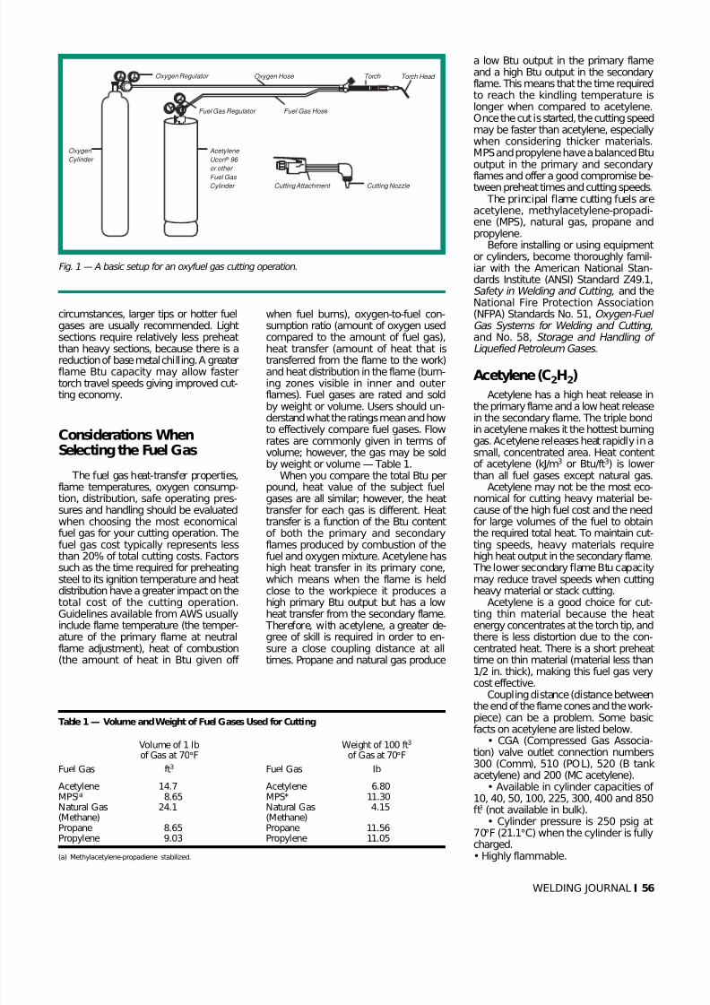
Oxyfuel gas cutting (OFC) is definedas a group of cutting processes used tosever metals by means of the chemicalreaction of oxygen with the base metalat elevated temperatures. The necessarytemperature is maintained by means of flames obtained from the combustion of
JIM DONAGHY is Shielding Gas Engineer,
Praxair, Inc., O’Fallon, Mo.
a specified fuel gas mixed with pureoxygen — Fig. 1. Oxyfuel gas cutting isbased on the rapid formation of ironoxide from the introduction of a high-pressure pure oxygen stream into the cut-ting envelope. Since iron oxide melts ata lower temperature than mild steel, thematerial is removed from the base metal.Iron oxide formation requires large vol-umes of oxygen with a minimum purity
of 99.5% combined with intense heat,which results in rapid oxidation. An in-crease in the temperature of the reactantsincreases the speed of the reaction.
Common oxyfuel cutting applica-tions are limited to carbon and low-alloy steels. These materials can be cuteconomically, and setup is simple andquick. For manual oxyfuel gas cutting,there is no power requirement andequipment costs are low. Materials from3/16 in. (4.7 mm) up to 4 in. (102 mm)thick are commonly cut using manualoxyfuel gas cutting. Material up to 8 ft
(2.4 m) in thickness is successfully cutusing machine cutting.
Oxyfuel gas flames heat the metal tokindling temperature (1650°F/899°C),at which point the high-pressure oxygenstream is added, while the heat of com-bustion helps to sustain the reaction bycontinuously heating the metal at theline of the cut. The preheat flame dis-lodges rust, scale and other contami-
nants from the surface of the workpiecebefore they affect the cutting reaction.In general practice, it is recommendedthat surface contamination be removedprior to the cutting operation. The pre-heat flame also protects the stream of high-pressure cutting oxygen from dilu-tion by air, blankets the hot metal oneither side of the cut and transmits heatinto the oxygen stream. As the thicknessof the metal to be cut increases, moreheat is required in order to maintaincutting speeds and keep the metal at itsignition temperature. Under these
E
55 WELDING JOURNAL
BY JIM DONAGHY
A Hastelloy X pipe with a 3/16-in.wall thickness is cut with a Nd:YAG laser. A nitrogen assist gas used withthe process assures a clean oxide- free cut.
Choose the Gas That’s Right for theCutting Operation
Matching the right gas to the cutting process can make the difference between a
costly ragged cut and a clean quality cut
7/28/2019 Choose the Gas That’s Right for the Cutting
http://slidepdf.com/reader/full/choose-the-gas-thats-right-for-the-cutting 3/8
circumstances, larger tips or hotter fuelgases are usually recommended. Lightsections require relatively less preheat
than heavy sections, because there is areduction of base metal chilling. A greaterflame Btu capacity may allow fastertorch travel speeds giving improved cut-ting economy.
Considerations WhenSelecting the Fuel Gas
The fuel gas heat-transfer properties,flame temperatures, oxygen consump-tion, distribution, safe operating pres-sures and handling should be evaluatedwhen choosing the most economicalfuel gas for your cutting operation. Thefuel gas cost typically represents lessthan 20% of total cutting costs. Factorssuch as the time required for preheatingsteel to its ignition temperature and heatdistribution have a greater impact on thetotal cost of the cutting operation.Guidelines available from AWS usuallyinclude flame temperature (the temper-ature of the primary flame at neutralflame adjustment), heat of combustion(the amount of heat in Btu given off
when fuel burns), oxygen-to-fuel con-sumption ratio (amount of oxygen usedcompared to the amount of fuel gas),
heat transfer (amount of heat that istransferred from the flame to the work)and heat distribution in the flame (burn-ing zones visible in inner and outerflames). Fuel gases are rated and soldby weight or volume. Users should un-derstand what the ratings mean and howto effectively compare fuel gases. Flowrates are commonly given in terms of volume; however, the gas may be soldby weight or volume — Table 1.
When you compare the total Btu perpound, heat value of the subject fuelgases are all similar; however, the heattransfer for each gas is different. Heattransfer is a function of the Btu contentof both the primary and secondaryflames produced by combustion of thefuel and oxygen mixture. Acetylene hashigh heat transfer in its primary cone,which means when the flame is heldclose to the workpiece it produces ahigh primary Btu output but has a lowheat transfer from the secondary flame. Therefore, with acetylene, a greater de-gree of skill is required in order to en-sure a close coupling distance at alltimes. Propane and natural gas produce
a low Btu output in the primary flameand a high Btu output in the secondaryflame. This means that the time requiredto reach the kindling temperature islonger when compared to acetylene.Once the cut is started, the cutting speedmay be faster than acetylene, especiallywhen considering thicker materials.MPS and propylene have a balanced Btuoutput in the primary and secondary
flames and offer a good compromise be-tween preheat times and cutting speeds.
The principal flame cutting fuels areacetylene, methylacetylene-propadi-ene (MPS), natural gas, propane andpropylene.
Before installing or using equipmentor cylinders, become thoroughly famil-iar with the American National Stan-dards Institute (ANSI) Standard Z49.1,Safety in Welding and Cutting, and theNational Fire Protection Association(NFPA) Standards No. 51, Oxygen-Fuel Gas Systems for Welding and Cutting,and No. 58, Storage and Handling of
Liquefied Petroleum Gases.
Acetylene (C2H2)
Acetylene has a high heat release inthe primary flame and a low heat releasein the secondary flame. The triple bondin acetylene makes it the hottest burninggas. Acetylene releases heat rapidly in asmall, concentrated area. Heat contentof acetylene (kJ/m3 or Btu/ft3) is lowerthan all fuel gases except natural gas.
Acetylene may not be the most eco-nomical for cutting heavy material be-cause of the high fuel cost and the needfor large volumes of the fuel to obtainthe required total heat. To maintain cut-ting speeds, heavy materials requirehigh heat output in the secondary flame. The lower secondary flame Btu capacitymay reduce travel speeds when cuttingheavy material or stack cutting.
Acetylene is a good choice for cut-ting thin material because the heatenergy concentrates at the torch tip, andthere is less distortion due to the con-centrated heat. There is a short preheattime on thin material (material less than1/2 in. thick), making this fuel gas verycost effective.
Coupling distance (distance between
the end of the flame cones and the work-piece) can be a problem. Some basicfacts on acetylene are listed below.
• CGA (Compressed Gas Associa-tion) valve outlet connection numbers300 (Comm), 510 (POL), 520 (B tankacetylene) and 200 (MC acetylene).
• Available in cylinder capacities of 10, 40, 50, 100, 225, 300, 400 and 850ft3 (not available in bulk).
• Cylinder pressure is 250 psig at70°F (21.1°C) when the cylinder is fullycharged.• Highly flammable.
WELDING JOURNAL 56
Fig. 1 — A basic setup for an oxyfuel gas cutting operation.
Table 1 — Volume and Weight of Fuel Gases Used for Cutting
Volume of 1 lb Weight of 100 ft3
of Gas at 70°F of Gas at 70°F
Fuel Gas ft3 Fuel Gas Ib
Acetylene 14.7 Acetylene 6.80MPS(a) 8.65 MPS* 11.30Natural Gas 24.1 Natural Gas 4.15(Methane) (Methane)Propane 8.65 Propane 11.56Propylene 9.03 Propylene 11.05
(a) Methylacetylene-propadiene stabilized.
Oxygen Regulator Oxygen Hose
Fuel Gas Hos e
Torch Torch Head
Cutting Nozzle Cutting Attachment
Acetylene
Ucon ® 96
or other
Fuel Gas Cylinder
Oxygen
Cylinder
Fuel Gas Regulator

7/28/2019 Choose the Gas That’s Right for the Cutting
http://slidepdf.com/reader/full/choose-the-gas-thats-right-for-the-cutting 4/8
• Gas is dissolved in acetone.• Withdrawal rate should not exceed
1/10th of cylinder capacity when thecylinder is fully charged (when cylindercontents have been partially depleted orthe ambient temperature is below 70°F,the withdraw rates are reduced).
• Colorless gas with a distinctive gar-lic-like odor.
• Lighter than air.
• Maximum safe delivery pressure is15 psig.
• Considerable tendency to backfire.• Unstable shock sensitivity.• Concentrations of 2.5 to 81%
acetylene by volume in air are easily ig-nited by a low-energy spark and maycause an explosion.
• Copper piping is not acceptable foracetylene.
• Can cause rapid asphyxiation in aconfined area that does not have ade-quate ventilation, although it is recom-mended for use by telephone companiesfor work in manholes as it will rise.
• Do not store gas cylinders in con-fined or unventilated spaces such as cab-inets, closets or tool chests. Do not trans-port cylinders in confined spaces suchas closed vans or automobile trunks.
Methylacetylene-Propadiene-Stabilized Gas(CH3C:CH)
Methylacetylene-propadiene-stabi-lized (MPS) gas has a high heat releasein its primary and secondary flames. The heat release in the primary coneis similar to acetylene. The outer flametemperature is similar to propane andpropylene. Methylacetylene-propadiene-stabilized mixtures combine the quali-ties of an acetylene flame with a moreeven heat distribution. The mixture burnshotter than propane or natural gas.
Methylacetylene-propadiene-stabi-lized preheat flame cones are at least 1.5times longer than acetylene preheatcones when used with one-piece tips.Gases of this type commonly use two-piece tips, which will help to lessen pre-heat times, and have the same lengthcones as acetylene. Training is often re-quired in order to use MPS to its best ad-
vantage. Below are the facts on this gas.• CGA (Compressed Gas Association)
valve outlet connection number 510.• Available in cylinder capacities of
7 1/2, 30, 70, 115 and 500 Ib. Alsoavailable in 1000 or 2000 gal on-sitebulk storage tanks.
• Cylinder pressure is 94 psig at 70°F.• Highly flammable.• Colorless gas with a strong distinc-
tive odor.• Withdrawal rate is about 3 1/2
times greater than acetylene.
• Poor vapor pressures at lower ser-vice temperatures will limit the with-drawal capacity in the northern UnitedStates and Canada during the wintermonths.
• MPS cylinders will last five times aslong as an acetylene cylinder of equalsize.
• MPS is acceptable for underwatercutting.
• Slight tendency to backfire.• Concentrations of 2.4 and 11.7%
MPS by volume in air are easily ignitedby a low-energy spark and may cause anexplosion.
• Can cause rapid asphyxiation in aconfined area that does not have ade-quate ventilation.
• MPS is heavier than air and willdisplace air in poorly ventilated areas.
• Do not store gas cylinders in con-fined or unventilated spaces such as cab-inets, closets or tool chests. Do nottransport cylinders in confined spacessuch as closed vans or automobile trunks.
Natural Gas (Methane CH4)
This product is usually suppliedthrough low-pressure pipelines from alocal utility. Injector torches are recom-mended in order to overcome the lowdelivery pressure. Preheat time is longerthan the other commonly available fuelgases. One benefit is that cylinders andbulk storage vessels are not required. Thecost of natural gas is less than other fuelgases, but increased preheat times usu-ally make this a false economy. The factson natural gas for cutting are as follows:
• Highly flammable.• Colorless gas with a distinctive odor.• Requires a properly designed cut-
ting tip.• Slight tendency to backfire.• Concentrations of 5.3 to 14% nat-
ural gas by volume in air are easily ig-nited by a low-energy spark and maycause an explosion.
• Can cause rapid asphyxiation in aconfined area that does not have ade-quate ventilation.
Propane (C3H8)
The flame temperature of propane islower than acetylene. The primaryflame releases low Btu similar to naturalgas, which increases preheat times. Theheat distribution in the flame can be anadvantage with thick material.
Propane is commonly used by scrapyards where cut quality is not critical tocut varying thickness of materials.Where cut quality is not a concern,propane may be a cost-effective fuelgas. Important information on this gas islisted below.
•Compressed Gas Association(CGA) valve outlet connection number510.
• Available in cylinder capacities of 20, 33, 43 and 100 Ib. Also available in500, 1000, 2000 gal and larger on-sitebulk storage tanks.
• Cylinder pressure 109 psig at 70°F.• Highly flammable.• Colorless gas with a distinctive odor.
• Slight tendency to backfire.• Concentrations of 2.2 to 9.5%
propane by volume in air are easily ig-nited by a low-energy spark and maycause an explosion.
• Can cause rapid asphyxiation in aconfined area that does not have ade-quate ventilation.
• Propane is heavier than air and willdisplace air in poorly ventilated areas.
• Do not store gas cylinders in con-fined or unventilated spaces such as cab-inets, closets, or tool chests. Do nottransport cylinders in confined spacessuch as closed vans or automobile trunks.
Propylene (C3H6)
Propylene has a high heat release inits primary and secondary flames. Theheat release in the primary flame cone issimilar to acetylene. The outer flametemperature is superior to acetylene.Propylene combines the qualities of anacetylene flame with the secondaryheating capacity of propane. The mix-ture burns hotter than propane; how-ever, the cutting speed should be calcu-lated before choosing this as the mosteconomical choice as your fuel gas (ref-erence enclosed cost analysis sheet).
Propylene preheat flame cones are atleast 1.5 times longer than acetylene pre-heat cones. Training is often required inorder to use propylene to its best advan-tage. Facts on propylene are as follows:
• CGA (Compressed Gas Association)valve outlet connection number 510.
• Available in cylinder capacities of 27, 63, 105 and 435 Ib. Also availablein 1000, 2000 gal and larger on-sitebulk storage tanks.
• Cylinder pressure 140 psi at 70°F.• Highly flammable.• Colorless gas with a distinctive
odor (natural odor).• Withdrawal rate is about 3 1/2
times greater than acetylene.• Propylene at any temperature has
the highest vapor pressure and with-draw rate of any of the liquefied fuelgases .
• Propylene cylinders will last fivetimes as long as an acetylene cylinder of equal size.
• Requires a properly designed cut-ting tip.
• Propylene is acceptable for under-water cutting.
57 WELDING JOURNAL
7/28/2019 Choose the Gas That’s Right for the Cutting
http://slidepdf.com/reader/full/choose-the-gas-thats-right-for-the-cutting 5/8
• Slight tendency to backfire.• Concentrations of 2.0 to 10.3%
propylene by volume in air are easily ig-
nited by a low-energy spark and maycause an explosion.• Can cause rapid asphyxiation in a
confined area that does not have ade-quate ventilation.
• Do not store gas cylinders in con-fined or unventilated spaces such as cab-inets, closets or tool chests. Do not trans-port cylinders in confined spaces suchas closed vans or automobile trunks.
Fuel Gas Cost Analysis
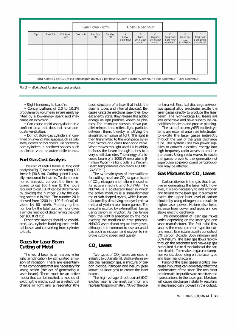
The unit of useful flame cutting costanalysis (Fig. 2) is the cost of cutting 100linear ft (30.5 m). Cutting speed is usu-ally measured in in./min. To do an eco-nomic analysis, convert the time re-quired to cut 100 linear ft. The hoursrequired to cut 100 ft can be determinedby dividing the number 20 by the cut-ting speed in in./min. The number 20 isderived from 1200 in. (100 ft of cut) di-vided by 60 min/h. Multiplying thisnumber by the total cost per hour givesa simple method of determining the costper 100 ft of cut.
Other cost savings should be consid-ered, i.e., cylinder handling cost, resid-ual losses and converting from cylinderto bulk.
Gases for Laser BeamCutting of Metal
The word laser is an acronym forlight amplification by stimulated emis-sion of radiation. There are essentiallythree components that are necessary forlasing action (the act of generating alaser beam). There must be an activemedia that can be excited, a method of exciting the media, such as an electricalcharge or light and a resonator (the
basic structure of a laser that holds theplasma tubes and internal devices). Be-cause unstable electrons seek their low-
est energy state, they release this addedenergy as light particles known as pho-tons. The resonator consists of two par-allel mirrors that reflect light particlesbetween them, thereby amplifying thesimulated emission of light. This light isthen transmitted to the workpiece by ei-ther mirrors or a glass fiber-optic cable.What makes this light useful is its abilityto focus the beam through a lens to avery small diameter. The energy of a fo-cused beam of a 1000-W resonator is 8-million W/cm2 (a light bulb is 1 W/cm2).Beam temperatures can reach 45,000°F(24,982°C).
The two main types of lasers utilizedfor cutting metal are CO2 (a gas mixtureof CO2, nitrogen and helium is used asits active media), and Nd:YAG. TheNd:YAG is a solid-state laser in whichthe active medium is a small-diameterrod or slab-shaped crystal, which is man-ufactured by dissolving neodymium in amatrix of yttrium aluminum garnet. Thecrystal is excited by external flash lampsusing xenon or krypton. As the lampsflash, the light is absorbed by the rodsexciting the medium to emit photons.Nd:YAG lasers do not require laser gases,although it is common to use an assistgas such as nitrogen and oxygen to im-
prove cutting speed and quality.
CO2 Lasers
Two types of CO2 lasers are used inindustry to cut material. Both systems ex-cite the resonator gas, a mixture of car-bon dioxide, nitrogen and helium (alsoknown as laser gas) to create the laserbeams.
The high-voltage direct-current (DC)excited laser is the most common andrepresents approximately 70% of the cur-
rent market. Electrical discharge betweentwo special alloy electrodes excite thelaser gases directly to produce the laser
beam. The high-voltage DC lasers areless expensive and have superpulse ca-pabilities for clean and precise piercing.
The radio-frequency (RF) excited sys-tems use external antennae (electrodes)to excite the laser gases indirectlythrough the wall of the glass dischargetube. This system uses two power sup-plies to convert electrical energy intohigh-frequency radio waves to producethe beam. Using radio waves to excitethe gases prevents the generation of superpulse, so piercing and part produc-tion may be affected.
Gas Mixtures for CO2Lasers
Carbon dioxide is the gas that is ac-tive in generating the laser light; how-ever, it is also necessary to add nitrogenand helium to the laser gas. It is easier toexcite the upper laser level of carbondioxide by using nitrogen and results inhigher laser power. Helium also helpsincrease laser power and gives a morestable electric discharge.
The composition of laser gas mixesvaries depending on the laser type andlaser manufacturer. The fast axial flowlaser is the most common type for cut-ting metal. Its mixture usually consists of
5% carbon dioxide, 35% nitrogen and60% helium. The laser gas flows rapidlythrough the resonator and make-up gasis required due to dissociation of the car-bon dioxide. The make-up gas consump-tion varies, depending on the laser typeand laser manufacturer.
Purity of the laser gases is critical be-cause impurities can adversely affect theperformance of the laser. The two mostproblematic impurities are moisture andhydrocarbons in the laser gas. Moisturewill cause discharge instability resultingin decreased gain (power) in the output.
Fig. 2 — Work sheet for fuel gas cost analysis.
WELDING JOURNAL 58
D Total Cost$ per hourA +B +C
Ehours per
100ft. =20/ipm
F Total Cost$ per 100 ft.cut =D x E
COxygen
cfh x $ percu. ft.
BFuel
cfh x $ percu. ft.
ALabor
$ per hour
Tip Plate Thk. Cut Speedipm
Fuel - cfh Pre. Oxy.cfh
Cut Oxy.cfh
Gas Flows - scfh Cost - $ per hour
Total Cost=$ per 100 ft. cut =hours per 100 ft. x $ per hour =20/ipm x (Labor $ per hour +Fuel $ per hour +Oxy. $ per hour)

7/28/2019 Choose the Gas That’s Right for the Cutting
http://slidepdf.com/reader/full/choose-the-gas-thats-right-for-the-cutting 6/8
Hydrocarbon impurities decompose inthe electric discharge and cause carbondeposits on the mirrors, reducing their re-flectivity. Laser power decreases becausethese deposits absorb the laser radiation. The damaged mirrors require replace-ment, and the replacement of mirrors isexpensive.
Many laser manufacturers require thefollowing minimum purity levels: helium
99.995%, nitrogen 99.995%, CO2
99.99%. These purity levels listed are notrequired for all lasers, and the manufac-turer’s specification should be referencedto determine the minimum recom-mended purity levels.
Premix laser gases supplied in high-pressure cylinders are available frommost specialty gas suppliers. For consis-tent quality, cylinders utilized for lasergases should not be used for other prod-ucts. Since moisture is a concern, anycylinder that has been exposed to atmos-phere (the cylinder valve left open andno positive pressure in the cylinder) may
need to be baked to remove moisture.Before filling high-pressure cylinders, avacuum is pulled; however, this proce-dure alone will not remove moisture.
Both premix high-pressure cylindersand pure gas cylinders are utilized tosupply lasing gases. Approximately 40%of the laser cutting equipment comesequipped with mixing units that blendthe optimum ratio of carbon dioxide,nitrogen and helium. The pure gas mustmeet the same purity levels. Pure gasescan be supplied in high-pressure cylin-ders, liquid containers or bulk storagevessels, depending on usage volumes.
The gas distribution system should beproperly designed for optimal laser per-formance. The piping system connectinga gas supply to a laser system can com-promise gas purity. Contaminants previ-ously absorbed by the inner surface of the piping system can be reintroducedinto the laser gas passing through thesystem. If the system is not tight, atmo-spheric moisture can contaminate the gassupply system, resulting in power loss inthe laser system. Rubber and plastichoses can be a problem because mois-ture can diffuse through these materials. The recommended hose to prevent mois-ture contamination is process stabilized
high-density polyethylene.In addition to piping and hoses,
choosing the proper gas-handling equip-ment is also recommended. All regula-tors, valves, manifolds and filters shouldbe designed specifically for use withhigh-purity gases. Specialty gas valvesand regulators are recommended.
Assist Gases
The majority of industrial lasers usean “assist” gas for cutting. By far, the larg-est use of gas during laser cutting is in
the cutting-assist gas. A wide range of
pressures are used, depending on thematerial type and thickness. The assistgas pressure may be between 10 to 250psig. The assist gas is fed into the head(Fig. 3) and exits through the cuttingnozzle along with the laser beam. Assistgases blow away molten metal and ox-ides from the kerf while offering lens pro-tection. The proper assist gas pressure isrequired in order to reduce dross levels. The common assist gases for cutting areoxygen and nitrogen. Clean, dry, com-pressed air can also be used for cuttingstainless steel or aluminum where edgequality is not important. Also, clean,dry, compressed air has recently beenfound to be acceptable for cutting galva-nized material. Argon is also used as anassist gas when cutting titanium becauseof the incompatibility of this metal withthe other assist gases listed.
When the assist gas is oxygen, thereis a chemical reaction of oxygen with thebase metal at elevated temperatures thatcontributes to the cutting process. Oxy-gen is always used on mild steel at pres-sures of approximately 10 to 60 psig.Oxygen can also be used with stainlesssteel or aluminum when edge quality isnot important. The purity of oxygen willaffect cutting speeds. Cutting speeds are
reduced as the purity level drops.When the assist gas is nitrogen, the
cutting process is generally referred toas “clean cut.” Nitrogen is used for highedge quality cutting of stainless, alu-minum and alloy steels. The use of ni-trogen can result in oxide-free edges thatcan be welded without cleaning the cutsurface. Because the nitrogen does notaid in the cutting process other than toblow away the molten metal and preventoxides from forming on the cut edge,higher pressures are required.
Plasma Arc Cutting Gases1
The plasma arc cutting (PAC) processsevers metal by melting a localized areawith a constricted arc and removing themolten material with a high-velocity jetof hot, ionized gas.
The major difference between PACand plasma arc welding is the velocityof the orifice gas. The higher velocity gasused in PAC removes or blows away themolten material. In some cases, a shield-ing gas as well as a cutting, or orifice gas,may be used. The shielding gas preventsoxidation of the cut surface. The PACprocess can be used to cut any electri-cally conductive metal if its thickness andshape permit full penetration by theplasma jet. Because the PAC process canbe used to cut nonferrous materials, andis faster than oxyfuel cutting in the less-than-two-in. thickness range for ferrousmaterials, it is ideal for many industrialapplications.
Conventional PlasmaArc Cutting
In conventional plasma arc cutting,the arc is constricted by a nozzle only;no shielding gas is added. Generally, the
cutting gas is tangentially injected aroundthe electrode.
The swirling action of the gas causesthe cooler (heavier) portions of the gasto move radially outward, forming a pro-tective boundary layer on the inside of the nozzle bore. This helps preventnozzle damage and extends its life. Elec-trode life is also improved since the arcattachment point (cathode spot) is forced
59 WELDING JOURNAL
1. This section on plasma arc cutting gases is from Shielding Gases Selection Manual,Praxair, Inc.
Fig. 3 — Schematic of a laser beam cutting head showing the entryway for an assist gas.
Nozzle Tip
Assist Gas
Kerf CutMaterial
Focal Lens
Focal
Length
Laser Head
Assist Gas

7/28/2019 Choose the Gas That’s Right for the Cutting
http://slidepdf.com/reader/full/choose-the-gas-thats-right-for-the-cutting 7/8
to move about and distribute its heat loadmore uniformly. Until the introductionof water injection plasma arc cutting,conventional plasma arc cutting was themost popular technique. It is still the bestmethod for cutting heavier stainless andaluminum plate.
Air Plasma Arc Cutting
Air plasma arc cutting was introducedin the early 1960s for cutting mild steel.Oxygen in the air provides additional en-ergy from the exothermic reaction withmolten steel, boosting cutting speedsabout 25%. Although this process canalso be used to cut stainless steel and alu-minum, the cut surface will be heavilyoxidized and is often unacceptable formany applications.
Dual-Flow PlasmaArc Cutting
Dual-flow plasma arc cutting is aslight modification of conventionalplasma arc cutting. It incorporates mostof the features of conventional plasma
arc cutting, but adds a secondary shield-ing gas around the nozzle.
Usually the cutting gas is nitrogen,and the shielding gas is selected ac-cording to the metal to be cut. Cuttingspeeds are slightly better than “conven-tional” plasma arc cutting on mild steel;however, cut quality is not acceptablefor many applications. Cutting speedand quality on stainless steel and alu-minum are essentially the same as inconventional plasma arc cutting.
Water Injection Plasma ArcCutting
In the water injection plasma arc cut-ting method, water is introduced insidethe nozzle to provide additional arc con-striction. Two modes of water injection
have been developed: radial injection(the water impinges the arc with no swirlcomponent) and swirl injection (thewater is introduced as a vortex swirlingin the same direction as the cutting gas).
The increased arc constriction pro-vided by the water improves cut square-ness and increases cutting speed. Thewater also protects the nozzle since itprovides cooling at the point of arc con-striction. The water completely protectsthe bottom half of the nozzle from theintense radiation, allowing complete in-sulation of the nozzle; hence, resistance
WELDING JOURNAL 60
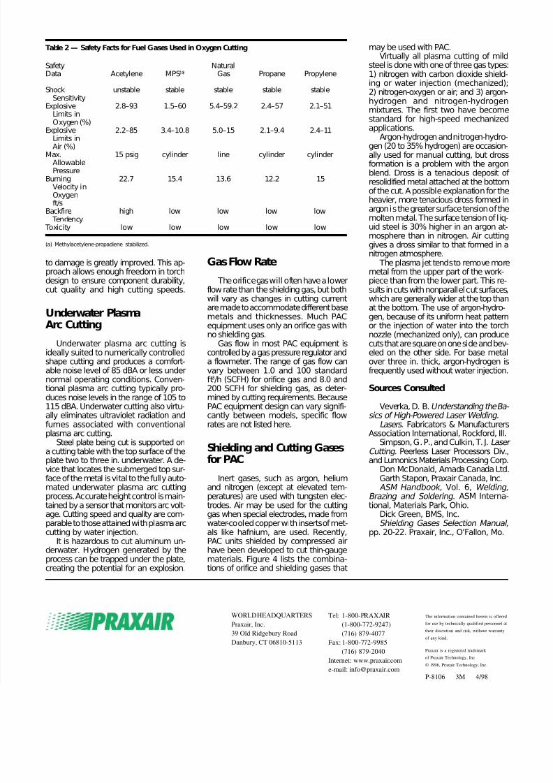
Fig. 4 — A selection guide for gases used in plasma arc cutting.
Key
Carbon Steel
Stainless Steel
& Nickel Alloys
Aluminum
Plasma Blend
Nitrogen*
Oxygen
Carbon Dioxide
H-35
Argon-Nitrogen
Orifice
Auxiliary
Orifice
Auxiliary
Orifice
Auxiliary
Orifice
Auxiliary
Orifice
Auxiliary
Orifice
Auxiliary
1/4" 1/2" 1" 2" 3" 4" 5" 6"
Thickness Range
* For Water Injection Plasma Cutting, nitrogen is the preferred plasma gas.
Notes – Depending upon equipment type, the following applies:
(1) An orifice gas is often used with no auxiliary gas.(2) When multiple auxiliary gases are shown for a single orifice gas,
only one auxiliary gas applies for a given application.(3) Cutting speed and quality can vary with gas selection.(4) This table is a composite based on gas requirements for currently available
PAC equipment. Use manufacturer’s recommendations for selecting gases.
7/28/2019 Choose the Gas That’s Right for the Cutting
http://slidepdf.com/reader/full/choose-the-gas-thats-right-for-the-cutting 8/8
to damage is greatly improved. This ap-
proach allows enough freedom in torchdesign to ensure component durability,cut quality and high cutting speeds.
Underwater PlasmaArc Cutting
Underwater plasma arc cutting isideally suited to numerically controlledshape cutting and produces a comfort-able noise level of 85 dBA or less undernormal operating conditions. Conven-tional plasma arc cutting typically pro-duces noise levels in the range of 105 to115 dBA. Underwater cutting also virtu-ally eliminates ultraviolet radiation andfumes associated with conventionalplasma arc cutting.
Steel plate being cut is supported ona cutting table with the top surface of theplate two to three in. underwater. A de-vice that locates the submerged top sur-face of the metal is vital to the fully auto-mated underwater plasma arc cuttingprocess. Accurate height control is main-tained by a sensor that monitors arc volt-age. Cutting speed and quality are com-parable to those attained with plasma arccutting by water injection.
It is hazardous to cut aluminum un-
derwater. Hydrogen generated by theprocess can be trapped under the plate,creating the potential for an explosion.
Gas Flow Rate
The orifice gas will often have a lowerflow rate than the shielding gas, but bothwill vary as changes in cutting currentare made to accommodate different basemetals and thicknesses. Much PACequipment uses only an orifice gas withno shielding gas.
Gas flow in most PAC equipment iscontrolled by a gas pressure regulator anda flowmeter. The range of gas flow canvary between 1.0 and 100 standardft3/h (SCFH) for orifice gas and 8.0 and200 SCFH for shielding gas, as deter-mined by cutting requirements. BecausePAC equipment design can vary signifi-cantly between models, specific flowrates are not listed here.
Shielding and Cutting Gasesfor PAC
Inert gases, such as argon, heliumand nitrogen (except at elevated tem-peratures) are used with tungsten elec-trodes. Air may be used for the cuttinggas when special electrodes, made fromwater-cooled copper with inserts of met-als like hafnium, are used. Recently,PAC units shielded by compressed air
have been developed to cut thin-gaugematerials. Figure 4 lists the combina-tions of orifice and shielding gases that
may be used with PAC.Virtually all plasma cutting of mild
steel is done with one of three gas types:1) nitrogen with carbon dioxide shield-ing or water injection (mechanized);2) nitrogen-oxygen or air; and 3) argon-hydrogen and nitrogen-hydrogenmixtures. The first two have becomestandard for high-speed mechanizedapplications.
Argon-hydrogen and nitrogen-hydro-gen (20 to 35% hydrogen) are occasion-ally used for manual cutting, but drossformation is a problem with the argonblend. Dross is a tenacious deposit of resolidified metal attached at the bottomof the cut. A possible explanation for theheavier, more tenacious dross formed inargon is the greater surface tension of themolten metal. The surface tension of liq-uid steel is 30% higher in an argon at-mosphere than in nitrogen. Air cuttinggives a dross similar to that formed in anitrogen atmosphere.
The plasma jet tends to remove more
metal from the upper part of the work-piece than from the lower part. This re-sults in cuts with nonparallel cut surfaces,which are generally wider at the top thanat the bottom. The use of argon-hydro-gen, because of its uniform heat patternor the injection of water into the torchnozzle (mechanized only), can producecuts that are square on one side and bev-eled on the other side. For base metalover three in. thick, argon-hydrogen isfrequently used without water injection.
Sources Consulted
Veverka, D. B. Understanding the Ba- sics of High-Powered Laser Welding.
Lasers. Fabricators & ManufacturersAssociation International, Rockford, Ill.
Simpson, G. P., and Culkin, T. J. Laser Cutting. Peerless Laser Processors Div.,and Lumonics Materials Processing Corp.
Don McDonald, Amada Canada Ltd.Garth Stapon, Praxair Canada, Inc.ASM Handbook, Vol. 6, Welding,
Brazing and Soldering. ASM Interna-tional, Materials Park, Ohio.
Dick Green, BMS, Inc.Shielding Gases Selection Manual,
pp. 20-22. Praxair, Inc., O’Fallon, Mo.
Table 2 — Safety Facts for Fuel Gases Used in Oxygen Cutting
Safety NaturalData Acetylene MPS(a) Gas Propane Propylene
Shock unstable stable stable stable stableSensitivity
Explosive 2.8–93 1.5–60 5.4–59.2 2.4–57 2.1–51Limits inOxygen (%)
Explosive 2.2–85 3.4–10.8 5.0–15 2.1–9.4 2.4–11
Limits inAir (%)
Max. 15 psig cylinder line cylinder cylinderAllowablePressure
Burning 22.7 15.4 13.6 12.2 15Velocity inOxygenft/s
Backfire high low low low low Tendency
Toxicity low low low low low
(a) Methylacetylene-propadiene stabilized.
The information contained herein is offered
for use by technically qualified personnel at
their discretion and risk, without warranty
of any kind.
Praxair is a registered trademark
of Praxair Technology, Inc.
© 1996, Praxair Technology, Inc.
P-8106 3M 4/98
WORLD HEADQUARTERS
Praxair, Inc.
39 Old Ridgebury Road
Danbury, CT 06810-5113
Tel: 1-800-PRAXAIR
(1-800-772-9247)
(716) 879-4077
Fax: 1-800-772-9985
(716) 879-2040
Internet: www.praxair.com
e-mail: [email protected]