chm worm geared motors and worm gear units chm worm geared
30
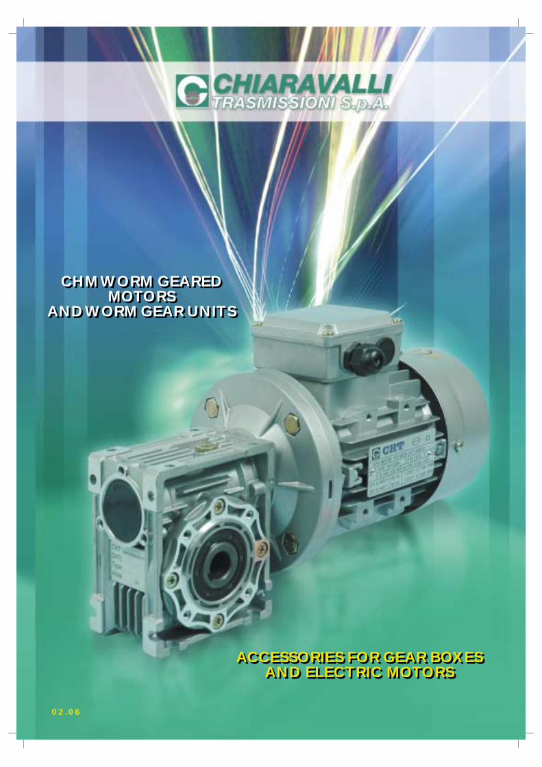
CHM WORM GEARED MOTORS AND WORM GEAR UNITS CHM WORM GEARED MOTORS AND WORM GEAR UNITS ACCESSORIES FOR GEAR BOXES AND ELECTRIC MOTORS ACCESSORIES FOR GEAR BOXES AND ELECTRIC MOTORS 02.06
Transcript of chm worm geared motors and worm gear units chm worm geared
CHM WORM GEAREDMOTORS
AND WORM GEAR UNITS
CHM WORM GEAREDMOTORS
AND WORM GEAR UNITS
ACCESSORIES FOR GEAR BOXESAND ELECTRIC MOTORS
ACCESSORIES FOR GEAR BOXESAND ELECTRIC MOTORS
02.06

INDEX
N.B. CHIARAVALLI TRASMISSIONI SPA reserves the right to modify this catalogue without compensation of any kind for damages deriving from any errors that may be present in it.
CHM – CHMR – CHME – CHMRE Worm geared motors and worm gear units Page 1
Introduction Page 2
CHM – CHMR – CHME – CHMRE Models – order example Page 3
CHM Motor mounting flanges Page 4
Mounting positions Page 5
Performance and dimensions with CHM 025 4-pole motors Page 6
Performance CHM 30 – 130 with 4-pole motors Page 7
CHM – CHMR – CHME – CHMRE 030 – 130 Dimensions Pages 8-9
CHTPC / CHM – CHME Worm gears with pre-stage modules Page 10
CHTPC / CHM – CHME Possible couplings and assembly instructions Page 11
Performance CHTPC / CHM with 4-pole motors Page 12
CHTPC / CHM Dimensions Page 13
Combined worm gears CHM / CHM – CHME Pages 14-15CHMR / CHM – CHME
Executions CHM / CHM – CHME Page 16 CHMR / CHM – CHME
Performance CHM / CHM with 4-pole motors Page 17
Combined gear dimensions Page 18
Torque arm kit – Single and double output shaft Page 19
Cover Page 20
BRM-S and BRM-D Reduction bushings kit Page 20
Technical data for CHT electric motors Page 21
Sizes and overall dimensions of CHT electric motors Page 21
Forced ventilation kit Page 22
Exploded view and spare parts list for worm gears Page 23
Use and maintenance instructions Page 24
General sales conditions Page 25
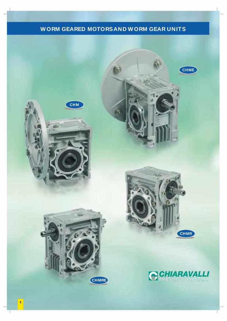
WORM GEARED MOTORS AND WORM GEAR UNITS
CHM
CHMRE
CHME
CHMR
1
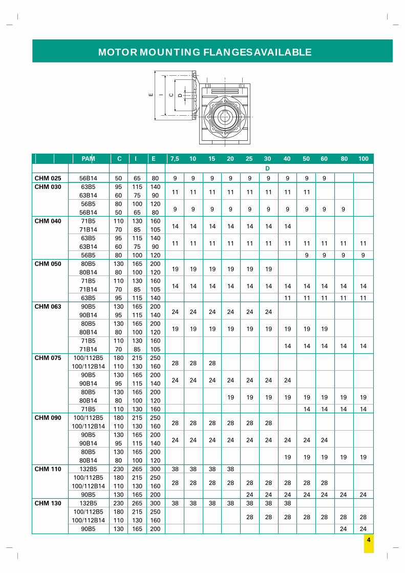
MOTOR MOUNTING FLANGES
Gears that are supplied with mounting flanges must be assembled with motors whose shaft and flange tolerances correspond to a “normalclass” of quality in order to avoid vibration and forcing of the input bearing. Motors supplied by Chiaravalli guarantee that this requirementis fulfilled. For ease of consultation, the correspondence of the size of the B5 and B14 motor with the sizes of the shaft and the motorconnection flange are shown in the following table.Remember that, as the motor connection flanges are separate from the body it is also possible to have a shaft / flange combination thatdoes not correspond to the table, e.g. 19/140, thereby offering adaptability for other non-unified models such as the brushless or directcurrent types.
MMF 056 063 071 080 090 100 112 132B5 9/120 11/140 14/160 19/200 24/200 28/250 28/250 38/300B14 9/80 11/90 14/105 19/120 24/140 28/160 28/160 38/200
INTRODUCTION
The worm gears made by Chiaravalli Trasmissioni SpA are square and are considerably versatile for mounting. The machining of thecomponents, carried out using numeric control machines, guarantees maximum precision for the restricted tolerances, producing aproduct that will remain reliable over time. The groups are constructed with aluminium casings from sizes 025 to 090, while the sizes110 and 130 are made from cast iron.All of the bodies are painted with RAL 9022 aluminium colour to protect the parts from aging and to give better protection against micro-blowholes that may be present in the aluminium.The gears are supplied with at least one filling plug that is also used during testing to check for possible leaks.A connection flange allows two gears to be combined in order to obtain high gear ratios.Four sizes of CHTPC pre-stage gears are available to pair with the gears; these are also constructed in aluminium and are painted likethe worm gears.All of the groups are supplied with a lubricant whose characteristics are described in the following table.
2
LUBRICATION
CHM 025 030 040 050 063 075 090 110 130 CHTPC 63 71 80 90
B3 0.02 0.04 0.08 0.15 0.30 0.55 1 3 4.5 0.05 0.07 0.15 0.16B8 0.02 0.04 0.08 0.15 0.30 0.55 1 2.2 3.3 0.05 0.07 0.15 0.16B6/B7 0.02 0.04 0.08 0.15 0.30 0.55 1 2.5 3.5 0.05 0.07 0.15 0.16V5 0.02 0.04 0.08 0.15 0.30 0.55 1 3 4.5 0.05 0.07 0.15 0.16V6 0.02 0.04 0.08 0.15 0.30 0.55 1 2.2 3.3 0.05 0.07 0.15 0.16
QUANTITY OF OIL IN LITRES
The size 025 to 090 gears are supplied complete with synthetic oil and therefore do not require any maintenance. The size 110 and 130gears are supplied with the quantity of mineral oil foreseen for the B3 assembly position. It is the client’s responsibility to adapt thequantity of oil to the assembly position and in addition, to substitute the filling plug, supplied closed for transport reasons, with the oneequipped with a hole attached to the gear. If the breather plug is not installed it may create internal pressure with a consequent leakageof oil from the oil seals. For the sizes 110 and 130 we recommend that the oil is changed after the running in period, approx. 300 workinghours.
CHM 025/090 CHM 110/130 CHTPC
Lubricant Synthetic Mineral Mineral Mineral Synthetic°C Ambient -25°C/+50°C -25°C/+50°C -5°C/+40°C -15°C/+25°C -25°C/+50°CISO VG320 VG320 VG460 VG220 VG320
AGIP TELIUM BLASIA 320 BLASIA 460 BLASIA 220 TELIUMVSF 320 VSF 320
SHELL TIVELA OMALA OMALA OMALA TIVELAOIL SC 320 OIL 320 OIL 460 OIL 220 OIL SC 320
IP TELIUM VSF MELLANA MELLANA MELLANA TELIUM VSFOIL 320 OIL 460 OIL 220
LUBRICATION
3
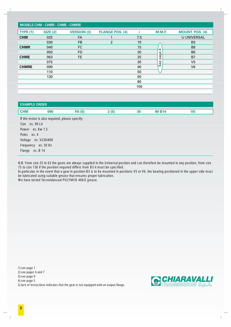
If the motor is also required, please specify:
Size es. 90 L4
Power es. Kw 1.5
Poles es. 4
Voltage es. V230/400
Frequency es. 50 Hz
Flange es. B 14
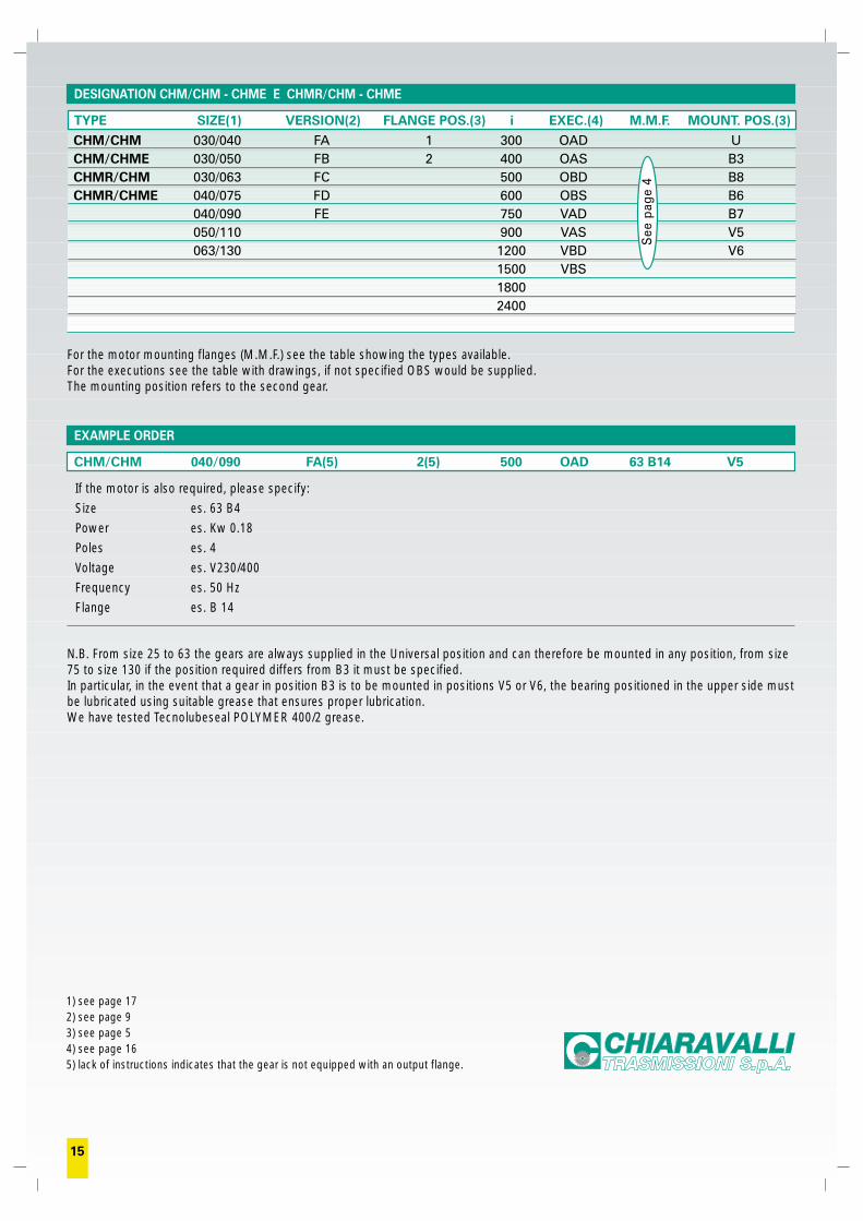
N.B. From size 25 to 63 the gears are always supplied in the Universal position and can therefore be mounted in any position, from size75 to size 130 if the position required differs from B3 it must be specified.In particular, in the event that a gear in position B3 is to be mounted in positions V5 or V6, the bearing positioned in the upper side mustbe lubricated using suitable grease that ensures proper lubrication.We have tested Tecnolubeseal POLYMER 400/2 grease.
1) see page 12) see pages 6 and 73) see page 94) see page 55) lack of instructions indicates that the gear is not equipped with an output flange.
MODELS CHM - CHMR - CHME - CHMRE
TYPE (1) SIZE (2) VERSION (3) FLANGE POS. (4) i M.M.F. MOUNT. POS. (4)
CHM 025 FA 1 7.5 U UNIVERSAL030 FB 2 10 B3
CHMR 040 FC 15 B8050 FD 20 B6
CHME 063 FE 25 B7075 30 V5
CHMRE 090 40 V6110 50130 60
80100
EXAMPLE ORDER
CHM 090 FA (5) 2 (5) 30 90 B14 V5
See
pag
e 4
4
MOTOR MOUNTING FLANGES AVAILABLE
CIE D
PAM C I E 7,5 10 15 20 25 30 40 50 60 80 100
D
CHM 025 56B14 50 65 80 9 9 9 9 9 9 9 9 9CHM 030 63B5 95 115 140
11 11 11 11 11 11 11 1163B14 60 75 9056B5 80 100 120
9 9 9 9 9 9 9 9 9 956B14 50 65 80CHM 040 71B5 110 130 160
14 14 14 14 14 14 1471B14 70 85 10563B5 95 115 140
11 11 11 11 11 11 11 11 11 11 1163B14 60 75 9056B5 80 100 120 9 9 9 9
CHM 050 80B5 130 165 20019 19 19 19 19 1980B14 80 100 120
71B5 110 130 16014 14 14 14 14 14 14 14 14 14 1471B14 70 85 105
63B5 95 115 140 11 11 11 11 11CHM 063 90B5 130 165 200
24 24 24 24 24 2490B14 95 115 14080B5 130 165 200
19 19 19 19 19 19 19 19 1980B14 80 100 12071B5 110 130 160
14 14 14 14 1471B14 70 85 105CHM 075 100/112B5 180 215 250
28 28 28100/112B14 110 130 16090B5 130 165 200
24 24 24 24 24 24 2490B14 95 115 14080B5 130 165 200
19 19 19 19 19 19 19 1980B14 80 100 12071B5 110 130 160 14 14 14 14
CHM 090 100/112B5 180 215 25028 28 28 28 28 28100/112B14 110 130 160
90B5 130 165 20024 24 24 24 24 24 24 24 2490B14 95 115 140
80B5 130 165 20019 19 19 19 1980B14 80 100 120
CHM 110 132B5 230 265 300 38 38 38 38100/112B5 180 215 250
28 28 28 28 28 28 28 28 28100/112B14 110 130 16090B5 130 165 200 24 24 24 24 24 24 24
CHM 130 132B5 230 265 300 38 38 38 38 38 38 38100/112B5 180 215 250
28 28 28 28 28 28 28100/112B14 110 130 16090B5 130 165 200 24 24
5
MOUNTING POSITION
POSITION OF TERMINAL BOX
N.B. The position of the terminal box always refers to the B3position.
B3 B6
B7 B8
F...1
V5
V6
F...2
1
1
1
3
1
1
1
B3
4
3
2
1
6
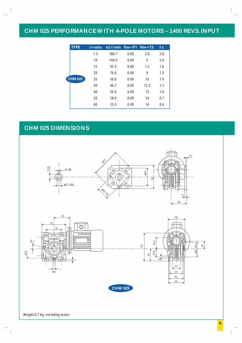
CHM 025 PERFORMANCE WITH 4-POLE MOTORS – 1400 REVS. INPUT
CHM 025 DIMENSIONS
CHM 025
Weight 0.7 Kg. excluding motor
7.5 186.7 0.09 3.8 2.8
10 140.0 0.09 5 2.4
15 93.3 0.09 7.2 1.6
20 70.0 0.09 9 1.3
25 56.0 0.09 10 1.0
30 46.7 0.09 12.3 1.1
40 35.0 0.09 13 1.0
50 28.0 0.09 14 0.7
60 23.3 0.09 14 0.6
TYPE i=ratio n2 r/min Kw=P1 Nm=T2 f.s.
CHM 025
H
10°
1) nessuna indicazione significa che il riduttore è privo di flangia in uscita.
TYPE i=ratio n2 r/min Kw=P1 Nm=T2 f.s.TYPE i=ratio n2 r/min Kw=P1 Nm=T2 f.s.
TYPE i=ratio n2 r/min Kw=P1 Nm=T2 f.s.TYPE i=ratio n2 r/min Kw=P1 Nm=T2 f.s.
TYPE i=ratio n2 r/min Kw=P1 Nm=T2 f.s.TYPE i=ratio n2 r/min Kw=P1 Nm=T2 f.s.
TYPE i=ratio n2 r/min Kw=P1 Nm=T2 f.s.TYPE i=ratio n2 r/min Kw=P1 Nm=T2 f.s.
7
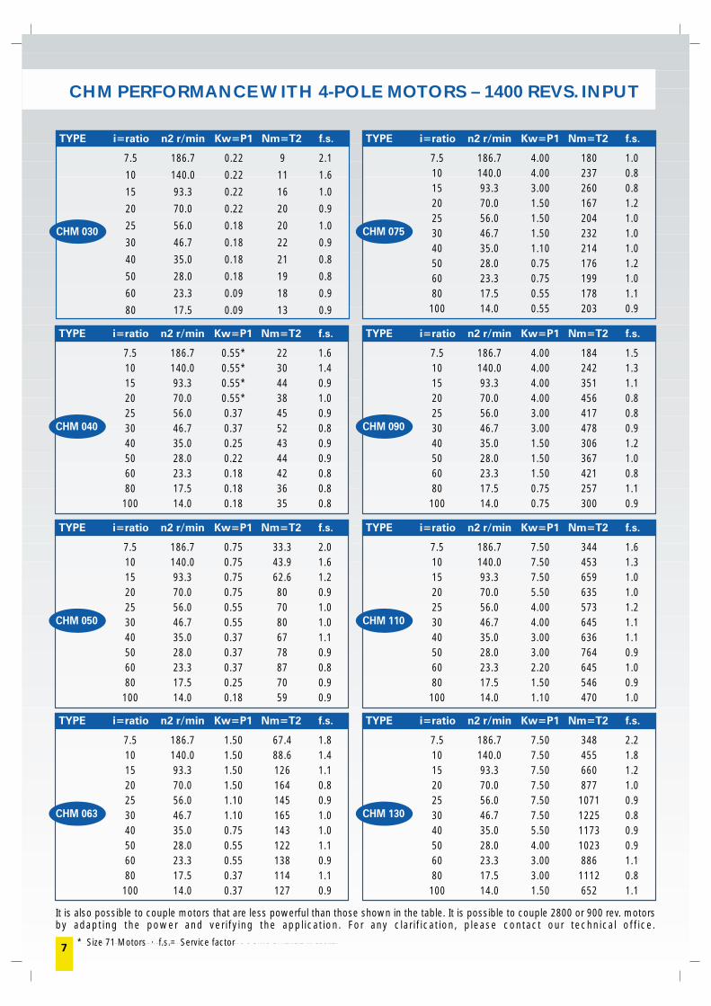
CHM PERFORMANCE WITH 4-POLE MOTORS – 1400 REVS. INPUT
* Size 71 Motors · f.s.= Service factor
It is also possible to couple motors that are less powerful than those shown in the table. It is possible to couple 2800 or 900 rev. motorsby adapting the power and verifying the application. For any clarification, please contact our technical office.
7.5 186.7 4.00 184 1.510 140.0 4.00 242 1.315 93.3 4.00 351 1.120 70.0 4.00 456 0.825 56.0 3.00 417 0.830 46.7 3.00 478 0.940 35.0 1.50 306 1.250 28.0 1.50 367 1.060 23.3 1.50 421 0.880 17.5 0.75 257 1.1100 14.0 0.75 300 0.9
7.5 186.7 0.55* 22 1.610 140.0 0.55* 30 1.415 93.3 0.55* 44 0.920 70.0 0.55* 38 1.025 56.0 0.37 45 0.930 46.7 0.37 52 0.840 35.0 0.25 43 0.950 28.0 0.22 44 0.960 23.3 0.18 42 0.880 17.5 0.18 36 0.8100 14.0 0.18 35 0.8
7.5 186.7 7.50 344 1.610 140.0 7.50 453 1.315 93.3 7.50 659 1.020 70.0 5.50 635 1.025 56.0 4.00 573 1.230 46.7 4.00 645 1.140 35.0 3.00 636 1.150 28.0 3.00 764 0.960 23.3 2.20 645 1.080 17.5 1.50 546 0.9100 14.0 1.10 470 1.0
7.5 186.7 0.75 33.3 2.010 140.0 0.75 43.9 1.615 93.3 0.75 62.6 1.220 70.0 0.75 80 0.925 56.0 0.55 70 1.030 46.7 0.55 80 1.040 35.0 0.37 67 1.150 28.0 0.37 78 0.960 23.3 0.37 87 0.880 17.5 0.25 70 0.9100 14.0 0.18 59 0.9
7.5 186.7 7.50 348 2.210 140.0 7.50 455 1.815 93.3 7.50 660 1.220 70.0 7.50 877 1.025 56.0 7.50 1071 0.930 46.7 7.50 1225 0.840 35.0 5.50 1173 0.950 28.0 4.00 1023 0.960 23.3 3.00 886 1.180 17.5 3.00 1112 0.8100 14.0 1.50 652 1.1
7.5 186.7 1.50 67.4 1.810 140.0 1.50 88.6 1.415 93.3 1.50 126 1.120 70.0 1.50 164 0.825 56.0 1.10 145 0.930 46.7 1.10 165 1.040 35.0 0.75 143 1.050 28.0 0.55 122 1.160 23.3 0.55 138 0.980 17.5 0.37 114 1.1100 14.0 0.37 127 0.9
7.5 186.7 4.00 180 1.010 140.0 4.00 237 0.815 93.3 3.00 260 0.820 70.0 1.50 167 1.225 56.0 1.50 204 1.030 46.7 1.50 232 1.040 35.0 1.10 214 1.050 28.0 0.75 176 1.260 23.3 0.75 199 1.080 17.5 0.55 178 1.1100 14.0 0.55 203 0.9
7.5 186.7 0.22 9 2.1
10 140.0 0.22 11 1.6
15 93.3 0.22 16 1.0
20 70.0 0.22 20 0.9
25 56.0 0.18 20 1.0
30 46.7 0.18 22 0.9
40 35.0 0.18 21 0.8
50 28.0 0.18 19 0.8
60 23.3 0.09 18 0.9
80 17.5 0.09 13 0.9
CHM 090CHM 040
CHM 110CHM 050
CHM 130CHM 063
CHM 075CHM 030
8
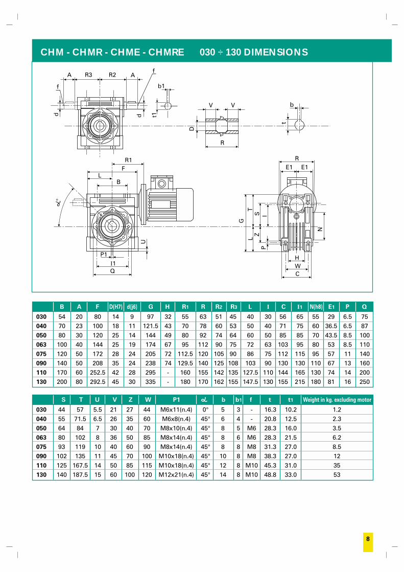
CHM - CHMR - CHME - CHMRE 030 ÷ 130 DIMENSIONS
B A F D(H7) d(j6) G H R1 R R2 R3 L I C I1 N(h8) E1 P Q
030 54 20 80 14 9 97 32 55 63 51 45 40 30 56 65 55 29 6.5 75
040 70 23 100 18 11 121.5 43 70 78 60 53 50 40 71 75 60 36.5 6.5 87
050 80 30 120 25 14 144 49 80 92 74 64 60 50 85 85 70 43.5 8.5 100
063 100 40 144 25 19 174 67 95 112 90 75 72 63 103 95 80 53 8.5 110
075 120 50 172 28 24 205 72 112.5 120 105 90 86 75 112 115 95 57 11 140
090 140 50 208 35 24 238 74 129.5 140 125 108 103 90 130 130 110 67 13 160
110 170 60 252.5 42 28 295 - 160 155 142 135 127.5 110 144 165 130 74 14 200
130 200 80 292.5 45 30 335 - 180 170 162 155 147.5 130 155 215 180 81 16 250
S T U V Z W P1 b b1 f t t1 Weight in kg. excluding motor
030 44 57 5.5 21 27 44 M6x11(n.4) 0° 5 3 - 16.3 10.2 1.2
040 55 71.5 6.5 26 35 60 M6x8(n.4) 45° 6 4 - 20.8 12.5 2.3
050 64 84 7 30 40 70 M8x10(n.4) 45° 8 5 M6 28.3 16.0 3.5
063 80 102 8 36 50 85 M8x14(n.4) 45° 8 6 M6 28.3 21.5 6.2
075 93 119 10 40 60 90 M8x14(n.4) 45° 8 8 M8 31.3 27.0 8.5
090 102 135 11 45 70 100 M10x18(n.4) 45° 10 8 M8 38.3 27.0 12
110 125 167.5 14 50 85 115 M10x18(n.4) 45° 12 8 M10 45.3 31.0 35
130 140 187.5 15 60 100 120 M12x21(n.4) 45° 14 8 M10 48.8 33.0 53
CWH
N
PI
ZL
G
ST
RE1
Q
P1
U
BL
FR1
b1
AR2
t1dd
f
f
R3A
I1
D
R
VV b
t
E1
1) nessuna indicazione significa che il riduttore è privo di flangia in uscita.9
* The values marked have a slot instead of a hole, therefore the fixing centreline, value, may be within the range indicated, an intermediate valueis recommended.
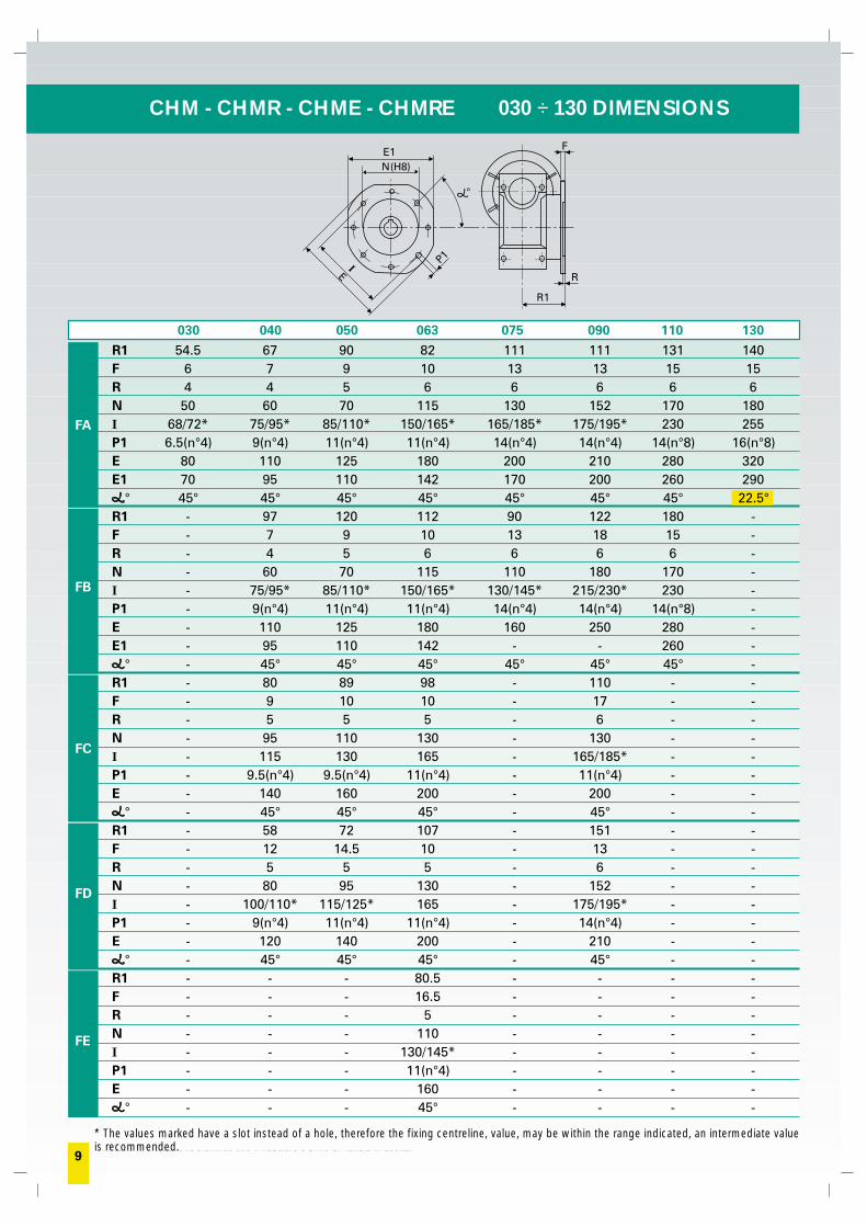
CHM - CHMR - CHME - CHMRE 030 ÷ 130 DIMENSIONS
030 040 050 063 075 090 110 130
FA
FB
FC
FD
FE
(H8)NE1 F
R
R1
EI P1
R1 54.5 67 90 82 111 111 131 140F 6 7 9 10 13 13 15 15R 4 4 5 6 6 6 6 6N 50 60 70 115 130 152 170 180I 68/72* 75/95* 85/110* 150/165* 165/185* 175/195* 230 255P1 6.5(n°4) 9(n°4) 11(n°4) 11(n°4) 14(n°4) 14(n°4) 14(n°8) 16(n°8)E 80 110 125 180 200 210 280 320E1 70 95 110 142 170 200 260 290
° 45° 45° 45° 45° 45° 45° 45° 22.5°R1 - 97 120 112 90 122 180 -F - 7 9 10 13 18 15 -R - 4 5 6 6 6 6 -N - 60 70 115 110 180 170 -I - 75/95* 85/110* 150/165* 130/145* 215/230* 230 -P1 - 9(n°4) 11(n°4) 11(n°4) 14(n°4) 14(n°4) 14(n°8) -E - 110 125 180 160 250 280 -E1 - 95 110 142 - - 260 -
° - 45° 45° 45° 45° 45° 45° -R1 - 80 89 98 - 110 - -F - 9 10 10 - 17 - -R - 5 5 5 - 6 - -N - 95 110 130 - 130 - -I - 115 130 165 - 165/185* - -P1 - 9.5(n°4) 9.5(n°4) 11(n°4) - 11(n°4) - -E - 140 160 200 - 200 - -
° - 45° 45° 45° - 45° - -R1 - 58 72 107 - 151 - -F - 12 14.5 10 - 13 - -R - 5 5 5 - 6 - -N - 80 95 130 - 152 - -I - 100/110* 115/125* 165 - 175/195* - -P1 - 9(n°4) 11(n°4) 11(n°4) - 14(n°4) - -E - 120 140 200 - 210 - -
° - 45° 45° 45° - 45° - -R1 - - - 80.5 - - - -F - - - 16.5 - - - -R - - - 5 - - - -N - - - 110 - - - -I - - - 130/145* - - - -P1 - - - 11(n°4) - - - -E - - - 160 - - - -
° - - - 45° - - - -
10
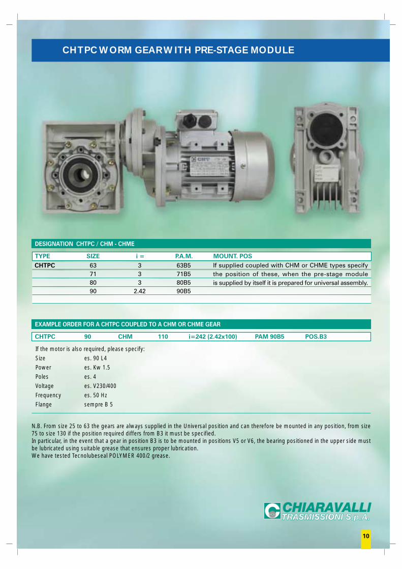
CHTPC WORM GEAR WITH PRE-STAGE MODULE
DESIGNATION CHTPC / CHM - CHME
TYPE SIZE i = P.A.M. MOUNT. POS
CHTPC 63 3 63B571 3 71B580 3 80B590 2.42 90B5
If the motor is also required, please specify:
Size es. 90 L4
Power es. Kw 1.5
Poles es. 4
Voltage es. V230/400
Frequency es. 50 Hz
Flange sempre B 5
N.B. From size 25 to 63 the gears are always supplied in the Universal position and can therefore be mounted in any position, from size75 to size 130 if the position required differs from B3 it must be specified.In particular, in the event that a gear in position B3 is to be mounted in positions V5 or V6, the bearing positioned in the upper side mustbe lubricated using suitable grease that ensures proper lubrication.We have tested Tecnolubeseal POLYMER 400/2 grease.
EXAMPLE ORDER FOR A CHTPC COUPLED TO A CHM OR CHME GEAR
CHTPC 90 CHM 110 i=242 (2.42x100) PAM 90B5 POS.B3
If supplied coupled with CHM or CHME types specifythe position of these, when the pre-stage moduleis supplied by itself it is prepared for universal assembly.
1) nessuna indicazione significa che il riduttore è privo di flangia in uscita.11
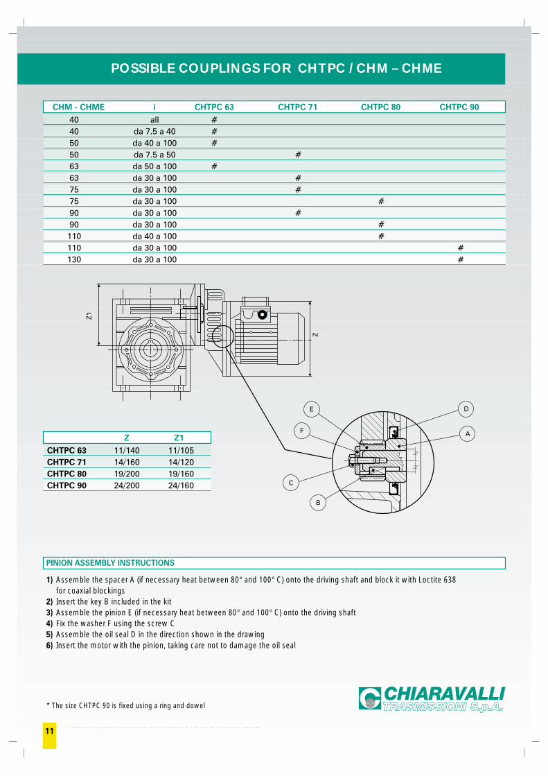
POSSIBLE COUPLINGS FOR CHTPC / CHM – CHME
CHM - CHME i CHTPC 63 CHTPC 71 CHTPC 80 CHTPC 90
40 all #40 da 7.5 a 40 #50 da 40 a 100 #50 da 7.5 a 50 #63 da 50 a 100 #63 da 30 a 100 #75 da 30 a 100 #75 da 30 a 100 #90 da 30 a 100 #90 da 30 a 100 #110 da 40 a 100 #110 da 30 a 100 #130 da 30 a 100 #
Z Z1
CHTPC 63 11/140 11/105CHTPC 71 14/160 14/120CHTPC 80 19/200 19/160CHTPC 90 24/200 24/160
* The size CHTPC 90 is fixed using a ring and dowel
PINION ASSEMBLY INSTRUCTIONS
1) Assemble the spacer A (if necessary heat between 80° and 100° C) onto the driving shaft and block it with Loctite 638for coaxial blockings
2) Insert the key B included in the kit3) Assemble the pinion E (if necessary heat between 80° and 100° C) onto the driving shaft4) Fix the washer F using the screw C5) Assemble the oil seal D in the direction shown in the drawing6) Insert the motor with the pinion, taking care not to damage the oil seal
Z1
Z
E
F
C
B
A
D
12
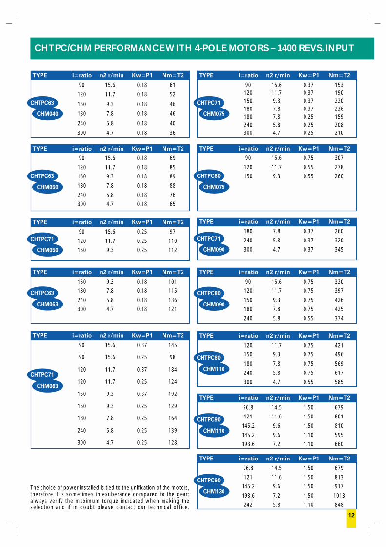
CHTPC/CHM PERFORMANCE WITH 4-POLE MOTORS – 1400 REVS. INPUT
The choice of power installed is tied to the unification of the motors,therefore it is sometimes in exuberance compared to the gear;always verify the maximum torque indicated when making theselection and if in doubt please contact our technical office.
TYPE i=ratio n2 r/min Kw=P1 Nm=T2
90 15.6 0.18 61
120 11.7 0.18 52
150 9.3 0.18 46
180 7.8 0.18 46
240 5.8 0.18 40
300 4.7 0.18 36
CHTPC63
CHM040
TYPE i=ratio n2 r/min Kw=P1 Nm=T2
90 15.6 0.18 69
120 11.7 0.18 85
150 9.3 0.18 89
180 7.8 0.18 88
240 5.8 0.18 76
300 4.7 0.18 65
CHTPC63
CHM050
TYPE i=ratio n2 r/min Kw=P1 Nm=T2
90 15.6 0.25 97
120 11.7 0.25 110
150 9.3 0.25 112
CHTPC71
CHM050
TYPE i=ratio n2 r/min Kw=P1 Nm=T2
150 9.3 0.18 101
180 7.8 0.18 115
240 5.8 0.18 136
300 4.7 0.18 121
CHTPC63
CHM063
TYPE i=ratio n2 r/min Kw=P1 Nm=T2
90 15.6 0.37 145
90 15.6 0.25 98
120 11.7 0.37 184
120 11.7 0.25 124
150 9.3 0.37 192
150 9.3 0.25 129
180 7.8 0.25 164
240 5.8 0.25 139
300 4.7 0.25 128
CHTPC71
CHM063
TYPE i=ratio n2 r/min Kw=P1 Nm=T2
90 15.6 0.37 153120 11.7 0.37 190150 9.3 0.37 220180 7.8 0.37 236180 7.8 0.25 159240 5.8 0.25 208300 4.7 0.25 210
CHTPC71
CHM075
TYPE i=ratio n2 r/min Kw=P1 Nm=T2
90 15.6 0.75 307
120 11.7 0.55 278
150 9.3 0.55 260CHTPC80
CHM075
TYPE i=ratio n2 r/min Kw=P1 Nm=T2
180 7.8 0.37 260
240 5.8 0.37 320
300 4.7 0.37 345
CHTPC71
CHM090
TYPE i=ratio n2 r/min Kw=P1 Nm=T2
90 15.6 0.75 320
120 11.7 0.75 397
150 9.3 0.75 426
180 7.8 0.75 425
240 5.8 0.55 374
CHTPC80
CHM090
TYPE i=ratio n2 r/min Kw=P1 Nm=T2
120 11.7 0.75 421
150 9.3 0.75 496
180 7.8 0.75 569
240 5.8 0.75 617
300 4.7 0.55 585
CHTPC80
CHM110
TYPE i=ratio n2 r/min Kw=P1 Nm=T2
96.8 14.5 1.50 679
121 11.6 1.50 801
145.2 9.6 1.50 810
145.2 9.6 1.10 595
193.6 7.2 1.10 660
CHTPC90
CHM110
TYPE i=ratio n2 r/min Kw=P1 Nm=T2
96.8 14.5 1.50 679
121 11.6 1.50 813
145.2 9.6 1.50 917
193.6 7.2 1.50 1013
242 5.8 1.10 848
CHTPC90
CHM130
1) nessuna indicazione significa che il riduttore è privo di flangia in uscita.13
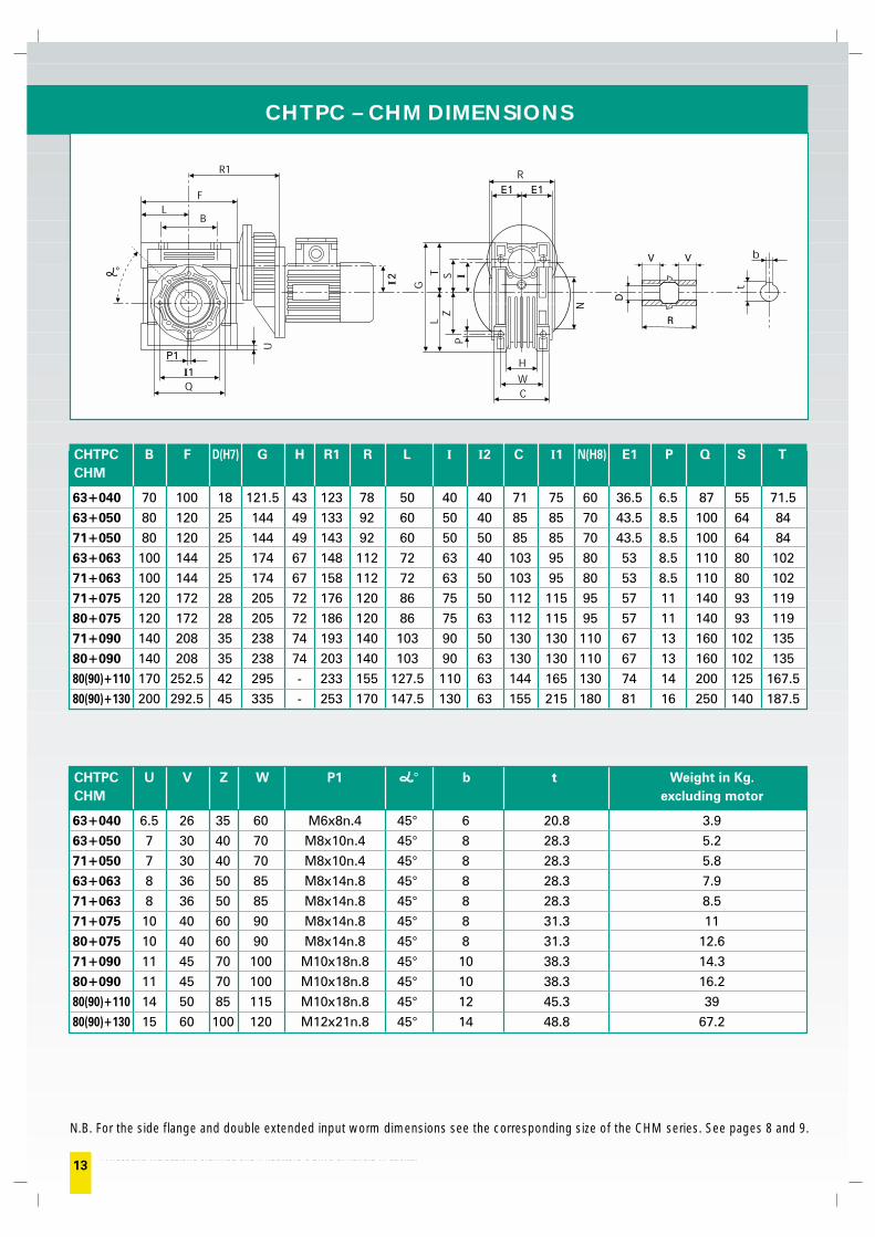
CHTPC – CHM DIMENSIONS
N.B. For the side flange and double extended input worm dimensions see the corresponding size of the CHM series. See pages 8 and 9.
P1
I1
I2
E1 E1
I
D
R
VV
CHTPC B F D(H7) G H R1 R L I I2 C I1 N(H8) E1 P Q S TCHM
63+040 70 100 18 121.5 43 123 78 50 40 40 71 75 60 36.5 6.5 87 55 71.5
63+050 80 120 25 144 49 133 92 60 50 40 85 85 70 43.5 8.5 100 64 84
71+050 80 120 25 144 49 143 92 60 50 50 85 85 70 43.5 8.5 100 64 84
63+063 100 144 25 174 67 148 112 72 63 40 103 95 80 53 8.5 110 80 102
71+063 100 144 25 174 67 158 112 72 63 50 103 95 80 53 8.5 110 80 102
71+075 120 172 28 205 72 176 120 86 75 50 112 115 95 57 11 140 93 119
80+075 120 172 28 205 72 186 120 86 75 63 112 115 95 57 11 140 93 119
71+090 140 208 35 238 74 193 140 103 90 50 130 130 110 67 13 160 102 135
80+090 140 208 35 238 74 203 140 103 90 63 130 130 110 67 13 160 102 135
80(90)+110 170 252.5 42 295 - 233 155 127.5 110 63 144 165 130 74 14 200 125 167.5
80(90)+130 200 292.5 45 335 - 253 170 147.5 130 63 155 215 180 81 16 250 140 187.5
CHTPC U V Z W P1 ° b t Weight in Kg.CHM excluding motor
63+040 6.5 26 35 60 M6x8n.4 45° 6 20.8 3.9
63+050 7 30 40 70 M8x10n.4 45° 8 28.3 5.2
71+050 7 30 40 70 M8x10n.4 45° 8 28.3 5.8
63+063 8 36 50 85 M8x14n.8 45° 8 28.3 7.9
71+063 8 36 50 85 M8x14n.8 45° 8 28.3 8.5
71+075 10 40 60 90 M8x14n.8 45° 8 31.3 11
80+075 10 40 60 90 M8x14n.8 45° 8 31.3 12.6
71+090 11 45 70 100 M10x18n.8 45° 10 38.3 14.3
80+090 11 45 70 100 M10x18n.8 45° 10 38.3 16.2
80(90)+110 14 50 85 115 M10x18n.8 45° 12 45.3 39
80(90)+130 15 60 100 120 M12x21n.8 45° 14 48.8 67.2
14
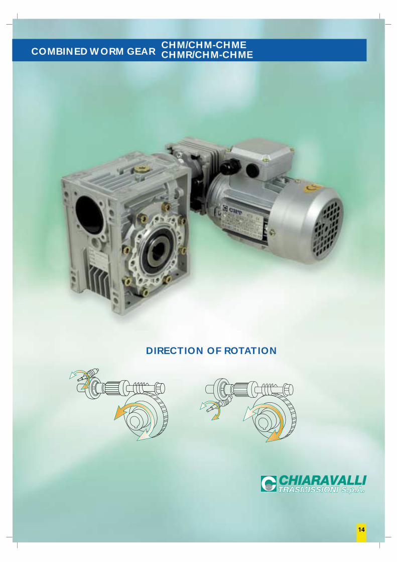
COMBINED WORM GEAR CHMR/CHM-CHMECHM/CHM-CHME
DIRECTION OF ROTATION
15
If the motor is also required, please specify:
Size es. 63 B4
Power es. Kw 0.18
Poles es. 4
Voltage es. V230/400
Frequency es. 50 Hz
Flange es. B 14
N.B. From size 25 to 63 the gears are always supplied in the Universal position and can therefore be mounted in any position, from size75 to size 130 if the position required differs from B3 it must be specified.In particular, in the event that a gear in position B3 is to be mounted in positions V5 or V6, the bearing positioned in the upper side mustbe lubricated using suitable grease that ensures proper lubrication.We have tested Tecnolubeseal POLYMER 400/2 grease.
1) see page 172) see page 93) see page 54) see page 165) lack of instructions indicates that the gear is not equipped with an output flange.
DESIGNATION CHM/CHM - CHME E CHMR/CHM - CHME
TYPE SIZE(1) VERSION(2) FLANGE POS.(3) i EXEC.(4) M.M.F. MOUNT. POS.(3)
CHM/CHM 030/040 FA 1 300 OAD UCHM/CHME 030/050 FB 2 400 OAS B3CHMR/CHM 030/063 FC 500 OBD B8CHMR/CHME 040/075 FD 600 OBS B6
040/090 FE 750 VAD B7050/110 900 VAS V5063/130 1200 VBD V6
1500 VBS18002400
EXAMPLE ORDER
CHM/CHM 040/090 FA(5) 2(5) 500 OAD 63 B14 V5
For the motor mounting flanges (M.M.F.) see the table showing the types available.For the executions see the table with drawings, if not specified OBS would be supplied.The mounting position refers to the second gear.
See
pag
e 4
16
EXECUTION
OAD OAS
OBD
The execution determines the mounting position of the first gear in relation to the second gear. If not otherwise specified at the time oforder, the group will be supplied in the OBS execution. The placing position refers to the second gear.
OBS
VAD VAS
VBS VBD
3 3
3 3
1 1
1 1
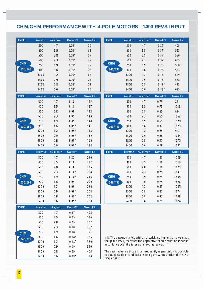
300 4.7 0.09* 70
400 3.5 0.09* 63
500 2.8 0.09* 57
600 2.3 0.09* 72
750 1.9 0.09* 72
900 1.6 0.09* 73
1200 1.2 0.09* 65
1500 0.9 0.09* 73
1800 0.8 0.09* 73
2400 0.6 0.09* 65
TYPE i=ratio n2 r/min Kw=P1 Nm=T2TYPE i=ratio n2 r/min Kw=P1 Nm=T2
TYPE i=ratio n2 r/min Kw=P1 Nm=T2TYPE i=ratio n2 r/min Kw=P1 Nm=T2
300 4.7 0.09* 70
400 3.5 0.09* 63
500 2.8 0.09* 57
600 2.3 0.09* 72
750 1.9 0.09* 72
900 1.6 0.09* 73
1200 1.2 0.09* 65
1500 0.9 0.09* 73
1800 0.8 0.09* 73
2400 0.6 0.09* 65
TYPE i=ratio n2 r/min Kw=P1 Nm=T2
TYPE i=ratio n2 r/min Kw=P1 Nm=T2TYPE i=ratio n2 r/min Kw=P1 Nm=T2
17
N.B. The powers marked with an asterisk are higher than those thatthe gear allows, therefore the applicative choice must be made inaccordance with the torque and not the power.
The gear ratios are those most frequently requested. It is possibleto obtain multiple combinations using the various ratios of the twosingle gears.
300 4.7 0.75 871
400 3.5 0.75 1013
500 2.8 0.55 984
600 2.3 0.55 1062
750 1.9 0.55 1128
900 1.6 0.37 1079
1200 1.2 0.25 943
1500 0.9 0.25 1064
1800 0.8 0.25 1075
2400 0.6 0.18 1001
300 4.7 0.18 142
400 3.5 0.18 127
500 2.8 0.09 123
600 2.3 0.09 143
750 1.9 0.09 148
900 1.6 0.09* 141
1200 1.2 0.09* 118
1500 0.9 0.09* 139
1800 0.8 0.09* 155
2400 0.6 0.09* 124
300 4.7 1.50 1789
400 3.5 1.10 1519
500 2.8 1.10 1629
600 2.3 0.75 1631
750 1.9 0.75 1804
900 1.6 0.75 1826
1200 1.2 0.55 1705
1500 0.9 0.37 1674
1800 0.8 0.37 1698
2400 0.6 0.25 1624
300 4.7 0.22 210
400 3.5 0.18 222
500 2.8 0.18 205
600 2.3 0.18* 208
750 1.9 0.18* 216
900 1.6 0.09 200
1200 1.2 0.09 236
1500 0.9 0.09* 204
1800 0.8 0.09* 202
2400 0.6 0.09* 220
300 4.7 0.37 405
400 3.5 0.37 523
500 2.8 0.37 550
600 2.3 0.37 605
750 1.9 0.25 538
900 1.6 0.25 533
1200 1.2 0.18 629
1500 0.9 0.18 588
1800 0.8 0.18* 492
2400 0.6 0.18* 625
300 4.7 0.09* 70
400 3.5 0.09* 63
500 2.8 0.09* 57
600 2.3 0.09* 72
750 1.9 0.09* 72
900 1.6 0.09* 73
1200 1.2 0.09* 65
1500 0.9 0.09* 73
1800 0.8 0.09* 73
2400 0.6 0.09* 65
CHM
030/040
CHM
040/090
CHM
030/050
CHM
050/110
CHM
030/063
CHM
063/130
300 4.7 0.37 405
400 3.5 0.25 336
500 2.8 0.25 307
600 2.3 0.18 362
750 1.9 0.18 391
900 1.6 0.18* 325
1200 1.2 0.18* 359
1500 0.9 0.09 360
1800 0.8 0.09 404
2400 0.6 0.09* 330
CHM
040/075
CHM/CHM PERFORMANCE WITH 4-POLE MOTORS – 1400 REVS. INPUT
18
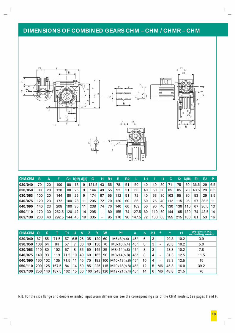
DIMENSIONS OF COMBINED GEARS CHM – CHM / CHMR – CHM
B A F C1 D(H7) d(j6) G H R1 R R2 L L1 I I1 C I2 N(H8) E1 E2 P
030/040 70 20 100 80 18 9 121.5 43 55 78 51 50 40 40 30 71 75 60 36.5 29 6.5
030/050 80 20 120 80 25 9 144 49 55 92 51 60 40 50 30 85 85 70 43.5 29 8.5
030/063 100 20 144 80 25 9 174 67 55 112 51 72 40 63 30 103 95 80 53 29 8.5
040/075 120 23 172 100 28 11 205 72 70 120 60 86 50 75 40 112 115 95 57 36.5 11
040/090 140 23 208 100 35 11 238 74 70 140 60 103 50 90 40 130 130 110 67 36.5 13
050/110 170 30 252.5 120 42 14 295 - 80 155 74 127.5 60 110 50 144 165 130 74 43.5 14
063/130 200 40 292.5 144 45 19 335 - 95 170 90 147.5 72 130 63 155 215 180 81 53 16
Q S T T1 U V Z Y W P1 a b b1 f t t1
030/040 87 55 71.5 57 6.5 26 35 120 60 M6x8(n.4) 45° 6 3 - 20.8 10.2 3.9
030/050 100 64 84 57 7 30 40 130 70 M8x10(n.4) 45° 8 3 - 28.3 10.2 5.0
030/063 110 80 102 57 8 36 50 145 85 M8x14(n.8) 45° 8 3 - 28.3 10.2 7.8
040/075 140 93 119 71.5 10 40 60 165 90 M8x14(n.8) 45° 8 4 - 31.3 12.5 11.5
040/090 160 102 135 71.5 11 45 70 182 100 M10x18(n.8) 45° 10 4 - 38.3 12.5 15
050/110 200 125 167.5 84 14 50 85 225 115 M10x18(n.8) 45° 12 5 M6 45.3 16.0 39.2
063/130 250 140 187.5 102 15 60 100 245 120 M12x21(n.4) 45° 14 6 M6 48.8 21.5 70
N.B. For the side flange and double extended input worm dimensions see the corresponding size of the CHM models. See pages 8 and 9.
CHM-CHM
CHM-CHM
D
R
VV
T1
f
t1
b1
I1
I2 W
I
Weight in Kg.excluding motor
300 4.7 0.09* 70
400 3.5 0.09* 63
500 2.8 0.09* 57
600 2.3 0.09* 72
750 1.9 0.09* 72
900 1.6 0.09* 73
1200 1.2 0.09* 65
1500 0.9 0.09* 73
1800 0.8 0.09* 73
2400 0.6 0.09* 65
19
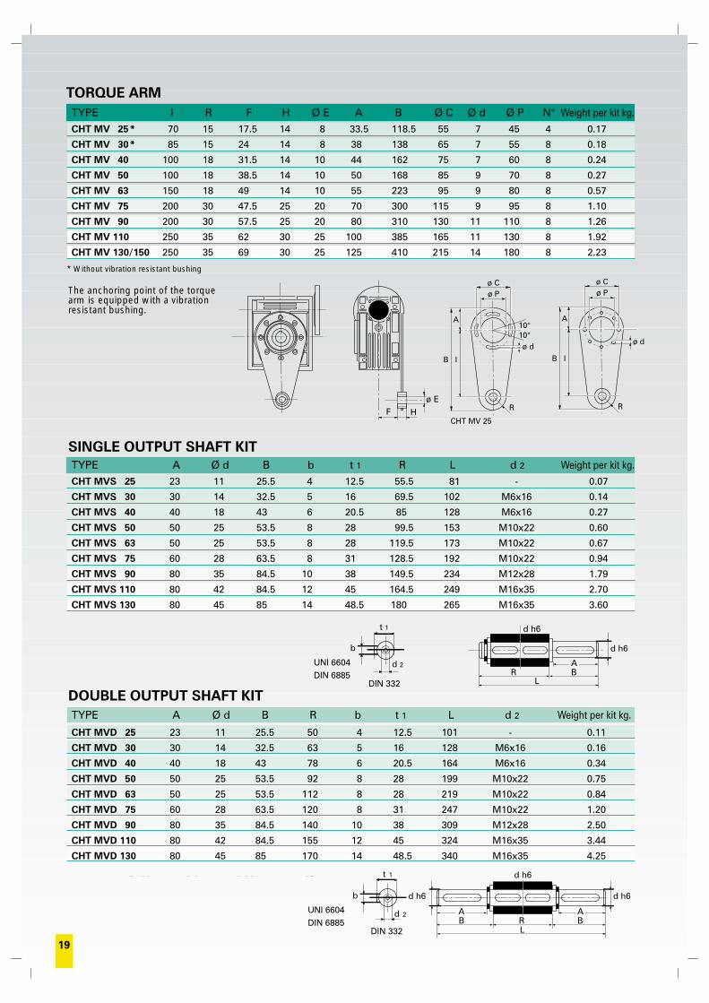
TYPE I R F H Ø E A B Ø C Ø d Ø P N° Weight per kit kg.CHT MV 25* 70 15 17.5 14 8 33.5 118.5 55 7 45 4 0.17
CHT MV 30* 85 15 24 14 8 38 138 65 7 55 8 0.18
CHT MV 40 100 18 31.5 14 10 44 162 75 7 60 8 0.24
CHT MV 50 100 18 38.5 14 10 50 168 85 9 70 8 0.27
CHT MV 63 150 18 49 14 10 55 223 95 9 80 8 0.57
CHT MV 75 200 30 47.5 25 20 70 300 115 9 95 8 1.10
CHT MV 90 200 30 57.5 25 20 80 310 130 11 110 8 1.26
CHT MV 110 250 35 62 30 25 100 385 165 11 130 8 1.92
CHT MV 130/150 250 35 69 30 25 125 410 215 14 180 8 2.23
TORQUE ARM
The anchoring point of the torquearm is equipped with a vibrationresistant bushing.
SINGLE OUTPUT SHAFT KIT
DOUBLE OUTPUT SHAFT KIT
F H
ø E
* Without vibration resistant bushing
ø Cø P
A
B I
R
ø d
ø Cø P
A
B I
R
ø d
10°10°
TYPE A Ø d B b t 1 R L d 2 Weight per kit kg.
TYPE A Ø d B R b t 1 L d 2 Weight per kit kg.
RL
BA
d h6
d h6
d 2
b
t 1
DIN 332DIN 6885UNI 6604
CHT MVS 25 23 11 25.5 4 12.5 55.5 81 - 0.07
CHT MVS 30 30 14 32.5 5 16 69.5 102 M6x16 0.14
CHT MVS 40 40 18 43 6 20.5 85 128 M6x16 0.27
CHT MVS 50 50 25 53.5 8 28 99.5 153 M10x22 0.60
CHT MVS 63 50 25 53.5 8 28 119.5 173 M10x22 0.67
CHT MVS 75 60 28 63.5 8 31 128.5 192 M10x22 0.94
CHT MVS 90 80 35 84.5 10 38 149.5 234 M12x28 1.79
CHT MVS 110 80 42 84.5 12 45 164.5 249 M16x35 2.70
CHT MVS 130 80 45 85 14 48.5 180 265 M16x35 3.60
CHT MVD 25 23 11 25.5 50 4 12.5 101 - 0.11
CHT MVD 30 30 14 32.5 63 5 16 128 M6x16 0.16
CHT MVD 40 40 18 43 78 6 20.5 164 M6x16 0.34
CHT MVD 50 50 25 53.5 92 8 28 199 M10x22 0.75
CHT MVD 63 50 25 53.5 112 8 28 219 M10x22 0.84
CHT MVD 75 60 28 63.5 120 8 31 247 M10x22 1.20
CHT MVD 90 80 35 84.5 140 10 38 309 M12x28 2.50
CHT MVD 110 80 42 84.5 155 12 45 324 M16x35 3.44
CHT MVD 130 80 45 85 170 14 48.5 340 M16x35 4.25
CHT MV 25
RL
BA
d h6
d h6t 1
d 2
DIN 332
b
DIN 6885UNI 6604
d h6
AB
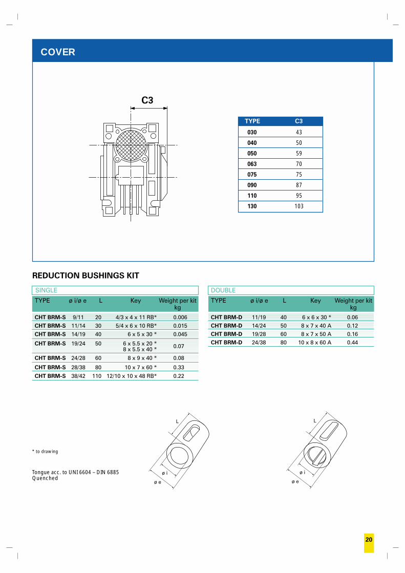
REDUCTION BUSHINGS KIT
20
COVER
ø e
ø i
L
TYPE ø i/ø e L Key Weight per kitkg
SINGLE
TYPE ø i/ø e L Key Weight per kitkg
DOUBLE
* to drawing
Tongue acc. to UNI 6604 – DIN 6885Quenched
CHT BRM-S 9/11 20 4/3 x 4 x 11 RB* 0.006
CHT BRM-S 11/14 30 5/4 x 6 x 10 RB* 0.015
CHT BRM-S 14/19 40 6 x 5 x 30 * 0.045
CHT BRM-S 19/24 50 6 x 5.5 x 20 * 0.078 x 5.5 x 40 *
CHT BRM-S 24/28 60 8 x 9 x 40 * 0.08
CHT BRM-S 28/38 80 10 x 7 x 60 * 0.33
CHT BRM-S 38/42 110 12/10 x 10 x 48 RB* 0.22
ø e
ø i
L
C3
TYPE C3
030 43
040 50
050 59
063 70
075 75
090 87
110 95
130 103
CHT BRM-D 11/19 40 6 x 6 x 30 * 0.06CHT BRM-D 14/24 50 8 x 7 x 40 A 0.12CHT BRM-D 19/28 60 8 x 7 x 50 A 0.16CHT BRM-D 24/38 80 10 x 8 x 60 A 0.44
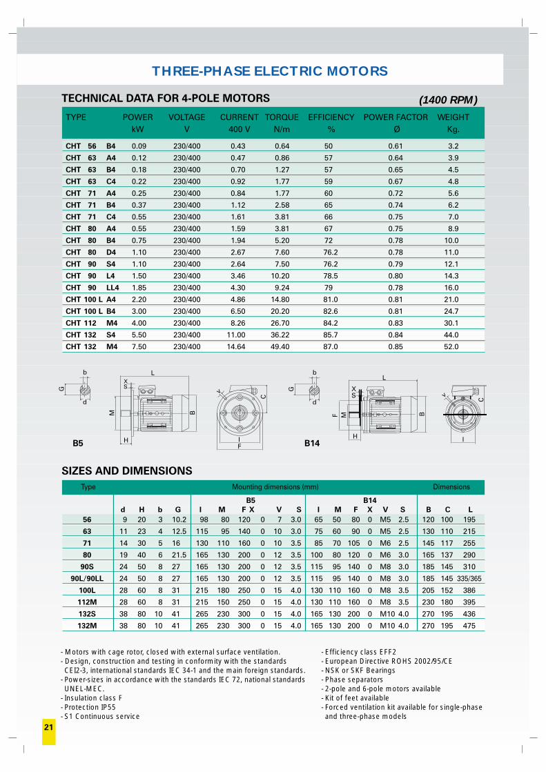
THREE-PHASE ELECTRIC MOTORS
TYPE POWER VOLTAGE CURRENT TORQUE EFFICIENCY POWER FACTOR WEIGHTkW V 400 V N/m % Ø Kg.
CHT 56 B4 0.09 230/400 0.43 0.64 50 0.61 3.2
CHT 63 A4 0.12 230/400 0.47 0.86 57 0.64 3.9
CHT 63 B4 0.18 230/400 0.70 1.27 57 0.65 4.5
CHT 63 C4 0.22 230/400 0.92 1.77 59 0.67 4.8
CHT 71 A4 0.25 230/400 0.84 1.77 60 0.72 5.6
CHT 71 B4 0.37 230/400 1.12 2.58 65 0.74 6.2
CHT 71 C4 0.55 230/400 1.61 3.81 66 0.75 7.0
CHT 80 A4 0.55 230/400 1.59 3.81 67 0.75 8.9
CHT 80 B4 0.75 230/400 1.94 5.20 72 0.78 10.0
CHT 80 D4 1.10 230/400 2.67 7.60 76.2 0.78 11.0
CHT 90 S4 1.10 230/400 2.64 7.50 76.2 0.79 12.1
CHT 90 L4 1.50 230/400 3.46 10.20 78.5 0.80 14.3
CHT 90 LL4 1.85 230/400 4.30 9.24 79 0.78 16.0
CHT 100 L A4 2.20 230/400 4.86 14.80 81.0 0.81 21.0
CHT 100 L B4 3.00 230/400 6.50 20.20 82.6 0.81 24.7
CHT 112 M4 4.00 230/400 8.26 26.70 84.2 0.83 30.1
CHT 132 S4 5.50 230/400 11.00 36.22 85.7 0.84 44.0
CHT 132 M4 7.50 230/400 14.64 49.40 87.0 0.85 52.0
TECHNICAL DATA FOR 4-POLE MOTORS
- Motors with cage rotor, closed with external surface ventilation.- Design, construction and testing in conformity with the standards CEI2-3, international standards IEC 34-1 and the main foreign standards.
- Power-sizes in accordance with the standards IEC 72, national standardsUNEL-MEC.
- Insulation class F- Protection IP55- S1 Continuous service
(1400 RPM)
Type Mounting dimensions (mm) Dimensions
56 9 20 3 10.2 98 80 120 0 7 3.0 65 50 80 0 M5 2.5 120 100 195
63 11 23 4 12.5 115 95 140 0 10 3.0 75 60 90 0 M5 2.5 130 110 215
71 14 30 5 16 130 110 160 0 10 3.5 85 70 105 0 M6 2.5 145 117 255
80 19 40 6 21.5 165 130 200 0 12 3.5 100 80 120 0 M6 3.0 165 137 290
90S 24 50 8 27 165 130 200 0 12 3.5 115 95 140 0 M8 3.0 185 145 310
90L/90LL 24 50 8 27 165 130 200 0 12 3.5 115 95 140 0 M8 3.0 185 145 335/365
100L 28 60 8 31 215 180 250 0 15 4.0 130 110 160 0 M8 3.5 205 152 386
112M 28 60 8 31 215 150 250 0 15 4.0 130 110 160 0 M8 3.5 230 180 395
132S 38 80 10 41 265 230 300 0 15 4.0 165 130 200 0 M10 4.0 270 195 436
132M 38 80 10 41 265 230 300 0 15 4.0 165 130 200 0 M10 4.0 270 195 475
SIZES AND DIMENSIONS
B5 B14d H b G I M F X V S I M F X V S B C L
- Efficiency class EFF2- European Directive ROHS 2002/95/CE- NSK or SKF Bearings- Phase separators- 2-pole and 6-pole motors available- Kit of feet available- Forced ventilation kit available for single-phaseand three-phase models
B5 B14H
XS
L
BM
v
C
IF
G
d
b
XS
L
H
F M B
C
v
I
G
d
b
21
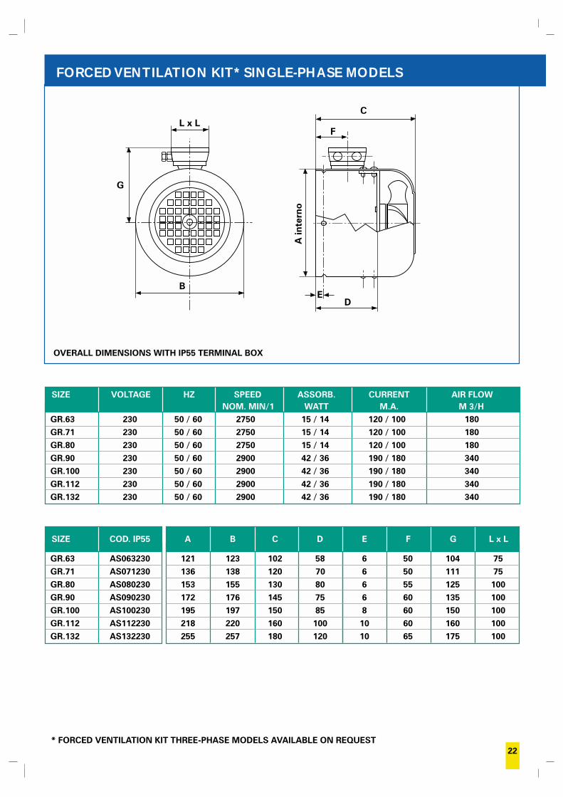
FORCED VENTILATION KIT* SINGLE-PHASE MODELS
OVERALL DIMENSIONS WITH IP55 TERMINAL BOX
SIZE VOLTAGE HZ SPEED ASSORB. CURRENT AIR FLOWNOM. MIN/1 WATT M.A. M 3/H
GR.63 230 50 / 60 2750 15 / 14 120 / 100 180GR.71 230 50 / 60 2750 15 / 14 120 / 100 180GR.80 230 50 / 60 2750 15 / 14 120 / 100 180GR.90 230 50 / 60 2900 42 / 36 190 / 180 340GR.100 230 50 / 60 2900 42 / 36 190 / 180 340GR.112 230 50 / 60 2900 42 / 36 190 / 180 340GR.132 230 50 / 60 2900 42 / 36 190 / 180 340
22
SIZE COD. IP55
GR.63 AS063230GR.71 AS071230GR.80 AS080230GR.90 AS090230GR.100 AS100230GR.112 AS112230GR.132 AS132230
A B C D E F G L x L
121 123 102 58 6 50 104 75136 138 120 70 6 50 111 75153 155 130 80 6 55 125 100172 176 145 75 6 60 135 100195 197 150 85 8 60 150 100218 220 160 100 10 60 160 100255 257 180 120 10 65 175 100
F
A in
tern
oD
E
CL x L
B
* FORCED VENTILATION KIT THREE-PHASE MODELS AVAILABLE ON REQUEST
G
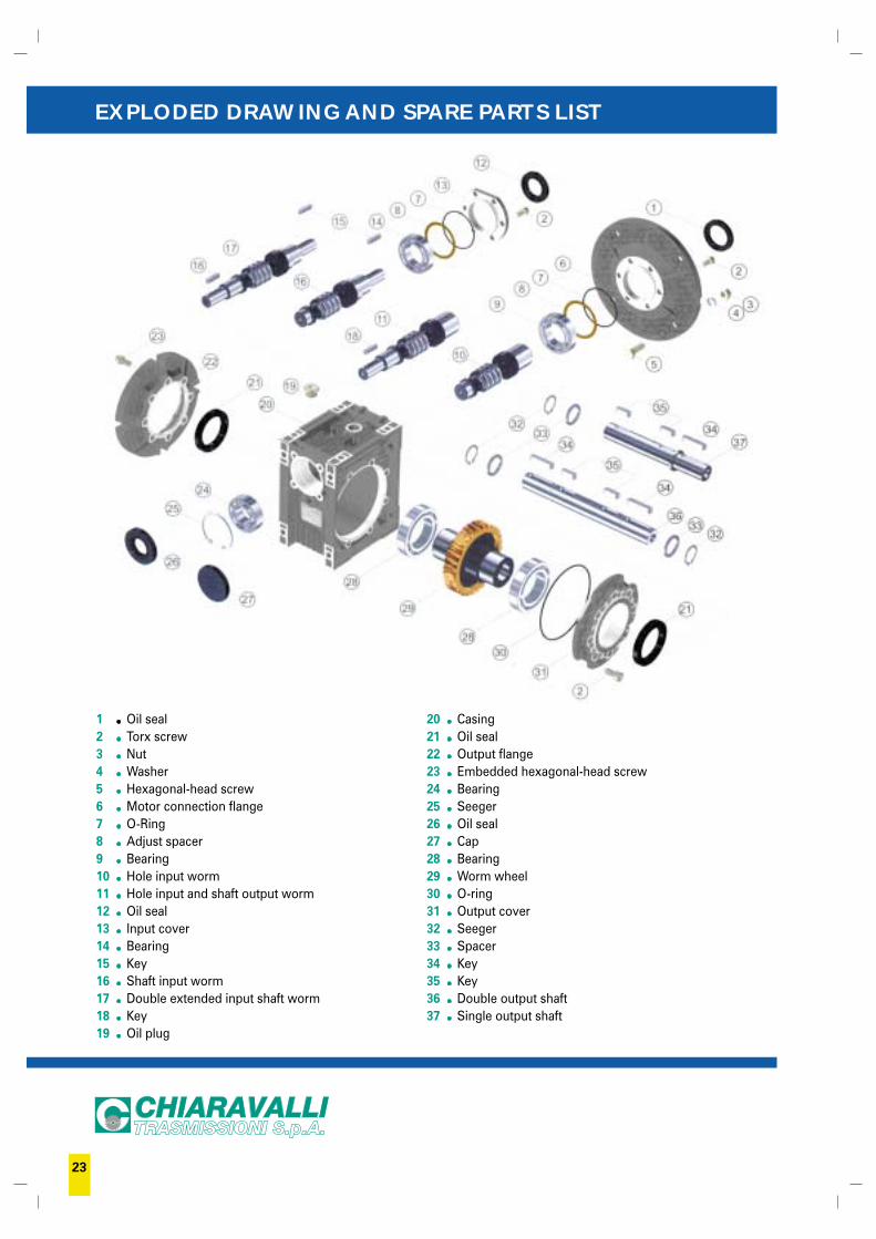
EXPLODED DRAWING AND SPARE PARTS LIST
1 Oil seal2 Torx screw3 Nut4 Washer5 Hexagonal-head screw6 Motor connection flange7 O-Ring8 Adjust spacer9 Bearing10 Hole input worm11 Hole input and shaft output worm12 Oil seal13 Input cover14 Bearing15 Key16 Shaft input worm17 Double extended input shaft worm18 Key19 Oil plug
20 Casing21 Oil seal22 Output flange23 Embedded hexagonal-head screw24 Bearing25 Seeger26 Oil seal27 Cap28 Bearing29 Worm wheel30 O-ring31 Output cover32 Seeger33 Spacer34 Key35 Key36 Double output shaft37 Single output shaft
23

INSTALLATION
· The data shown on the identification name plate must correspond to the gearordered
· The oil level, for the sizes 110 and 130 equipped with filling, draining and levelplug, must correspond to the quantity foreseen for the assembly position requested (see catalogue), in addition, always for the sizes indicated, it will be the client’s responsibility to substitute the blind plug, supplied for transport, withthe corresponding plug equipped with a bleed hole included in the supply withthe gear
· All of the other gears are supplied complete with permanent synthetic oil in aquantity that is sufficient for any assembly position
· The gear must be fixed on a flat surface that is sufficiently rigid in order to avoidany vibration
· The gear and the axis of the machine to be driven must be perfectly alignedo In the event that knocks, overloading or blockage of the machine are foreseen,the client must install a limiting device, joints, overload cut-out etc.
· Coupling with pinions, joints, pulleys and other parts must be done after the parts have been cleaned and knocks should be avoided while assembling as they could damage the bearings and other internal parts
· In the event that the motor is supplied by the client, he must check that the flange and shaft tolerances correspond to a “normal” class; our motors satisfy this requirement
· Check that the fixing screws for the gear and the related accessories are correctlytightened
· Take suitable measures to protect the groups from any aggressive atmosphericagents
· Where foreseen, protect rotating parts from any possible contact with the operators
· If the gears are painted, protect the oil seals and the machined surfaces· All of the gears are painted RAL 9022 grey
OPERATION AND RUNNING-IN
· To obtain the best performance the gears must first be run-in by gradually increasing the power in the first few hours of operation, in this phase an increasein temperature is considered normal
· In the event of defective operation, noise, oil leakage, etc. stop the gear immediatelyand, when possible, remove the cause. Alternatively, send the piece to our factoryto be controlled.
MAINTENANCE
· The worm gears from size 25 to size 90 and the pre-stage modules are lubricatedwith permanent synthetic oil and therefore do not require any maintenance
· The gears size 110 and 130 are lubricated with mineral oil and are equipped with a breather plug, therefore the oil level must be checked periodically and if necessary topped up with the same oil or one that is compatible with thoseindicated in our catalogue
· For the gears size 110 and 130 proceed with the substitution of the oil after the first 300 working hours, replacing it with the correct quantity in accordancewith the assembly position, as detailed in our catalogue, after the inside of the gear has been thoroughly washed
WAREHOUSE STORAGE
· If the warehouse storage will be for a long time, more than 3 months, the shaftsand machined surfaces should be protected using antioxidants and the oil sealsshould be greased
HANDLING
· Care must be taken not to damage the oil seals and the machined surfaces when handling the groups
DISPOSAL OF PACKAGING
· The packaging in which our gears are delivered should be sent to specialised companies for recycling if possible.
Use and maintenance instructions
24
1) ORDERS – Orders for special and standard material must always refer tooffers made by CHIARAVALLI Trasmissioni SpA.The orders are binding for the client. Once work has commenced no cancellationsor order reductions will be accepted unless the client reimburses the costs ofthe material and the work carried out up to the moment in which the order wassuspended. The quantity despatched can vary by ± 5% compared to the quantityordered.
2) PRICES – The prices are those in force at the date of order. All prices are forgoods delivered ex-works Premezzo, packing excluded. If there should be anyincrease in production and material costs over the duration of the supply,CHIARAVALLI Trasmissioni SpA reserves the right to adapt the prices accordingly,even for orders in course.
3) TERMS OF DELIVERY – Only the terms of delivery indicated by CHIARAVALLITrasmissioni SpA are to be considered valid. However, they must only be consideredas indicative. In the event of difficulty in the procurement of materials, strikes orin any event in all cases of force majeure, the terms of delivery will be automaticallyextended without CHIARAVALLI Trasmissioni SpA having to pay any reimbursementfor damages. The client is obligated to collect special material ordered when ready.
4) DELIVERIES – Deliveries are the responsibility of the purchaser and are carriedout at his own risk and peril. Any claims for shortages must be presented within8 days of receipt of the goods. If it is agreed that the cost of transport is to bepaid, even if only in part, by CHIARAVALLI Trasmissioni SpA, the latter reservesthe r ight to choose the most economical means of transpor t.5) PACKING – Packing will be invoiced at cost.
6) RETURNS – No returns for any reason will be accepted unless previouslyauthorised and with packing, any customs clearance and the return paid for bythe purchaser. To cover warehouse and administrative expenses a debit note willbe issued for approx. 15% of the value of the goods returned.
7) WARRANTY – CHIARAVALLI Trasmissioni SpA promises to repair or substitutefree of charge any parts that they recognise as being defective. The questionedgoods must be returned to the factory of CHIARAVALLI Trasmissioni SpA, freeof all expenses. The warranty will be considered cancelled in the event that theparts returned as defective have been repaired or tampered with. The repair ofdefective parts carried out by the purchaser will only be accepted after authorisationfrom CHIARAVALLI Trasmissioni SpA and after their approval of the cost estimate.CHIARAVALLI Trasmissioni SpA does not accept responsibility or pay anyreimbursement for damages that occur during the use of their products, even ifdefective.
8) RESPONSIBILITY – CHIARAVALLI Trasmissioni SpA does not accept responsibilityor pay any reimbursement for damages that occur during the use of their products,even if defective. CHIARAVALLI Trasmissioni SpA declines all responsibility in theexecution of parts to a client’s design under any patents.
9) PAYMENTS – Only payments carried out in the manner and terms agreedwill be considered valid. Once the due date of payment has passed, CHIARAVALLITrasmissioni SpA will calculate the interest on delayed payment at a rate that is3% higher than the legal one, retaining the right to demand payment. In the eventof delayed or missing payment by the purchaser, the company CHIARAVALLITrasmissioni SpA reserves the right to suspend deliveries of the orders in courseor to demand advance payment without having to pay any reimbursement orcompensation to the purchaser. Any dispute regarding materials in manufactureor already possessed by the purchaser does not free the latter from the commitmentof making the payment by the agreed date and for the whole amount of theinvoice without making any deductions.
10) OWNERSHIP –All of the goods despatched remain the proper ty ofCHIARAVALLI Trasmissioni SpA unti l the invoice is ful ly paid.
11) COMPETENT COURT – Any controversy concerning business relations withCHIARAVALLI Trasmissioni SpA will be dealt with under the jurisdiction of theCourt of Busto Arsizio.
GENERAL SALES CONDITIONS
25
dial
ogac
rea.
com
06/0
6
FILIALI ESTERECHIARAVALLI FRANCE SARL2, bis rue de Paris - F-77230 Villeneuve S/Dammartin FRANCEPh. 0033 1 60946666 - Fax 0033 1 60946660www.chiaravalli.fr - e-mail: [email protected]
CHIARAVALLI ESPAÑA SLC/. Industria S/N - E - 08592 Sant Marti de Centelles Barcelona ESPAÑAPh. 0034 93 8440099 - Fax 0034 93 8442193e-mail: [email protected]
CHIARAVALLI CZ s.r.o.Brnenská, 43 - 59101 Zd'ár nad Sázavou CZECH REPUBLICPh. 00420 566 686161 - Fax 00420 566 686171www.chiaravalli.cz - e-mail: [email protected]
CHIARAVALLI POLSKA Sp. z o.o.Ul. Polna, 133 - 87-100 TorunPh. 0048 56 6233000 - Fax 0048 56 6238246www.chiaravalli.pl - e-mail: [email protected]
FILIALI ITALIANE - DEPOSITIvia per Cedrate s/n21044 Cavaria con Premezzo - VARESETel. 0331 214511 - Fax 0331 215916
via 1° Maggio, 1040011 BOLOGNA / Anzola dell'EmiliaTel. 051 735290 - Fax 051 735366
via E. Cantoni, 3 - 20156 MILANOTel. 02 33400947 - Fax 02 33400949
via Portogallo, 11 int. 51 - 35127 PADOVATel. 049 8705205 - Fax 049 8705237
via G. B. Lulli, 61 H - 10148 TORINOTel. 011 2267146 - Fax 011 2266925
Via T. Minniti, 56021044 Cavaria con Premezzo (VA) - ItalyTel. +39.0331.214.511Fax +39.0331.219.430 735.067 - 735.090www.chiaravalli.come-mail: [email protected]