CHIPINO Operators Manual · This manual will assume you have the CHIPINO Starter Kit. If you have...
48
CHIPINO Operators Manual Version 2.2
Transcript of CHIPINO Operators Manual · This manual will assume you have the CHIPINO Starter Kit. If you have...

CHIPINO Operators Manual
Version 2.2
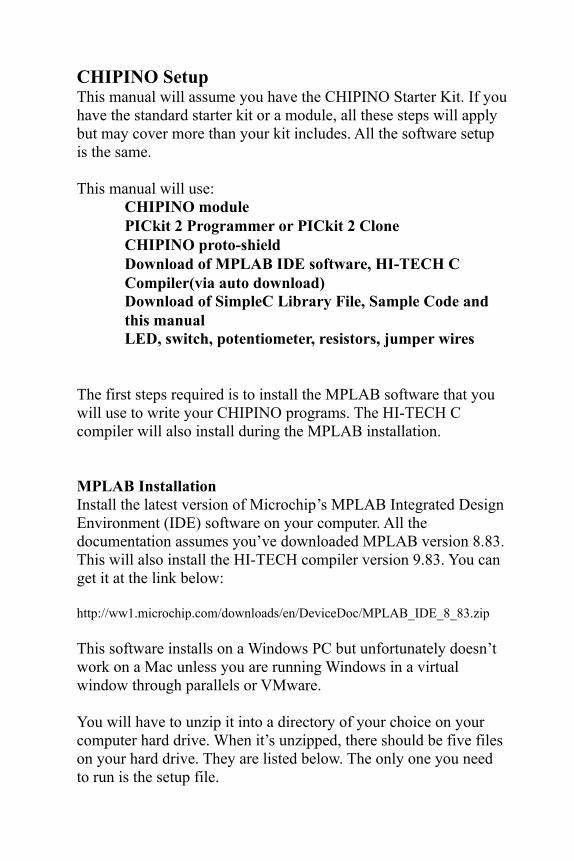
CHIPINO SetupThis manual will assume you have the CHIPINO Starter Kit. If you have the standard starter kit or a module, all these steps will apply but may cover more than your kit includes. All the software setup is the same.
This manual will use:� CHIPINO module� PICkit 2 Programmer or PICkit 2 Clone� CHIPINO proto-shield� Download of MPLAB IDE software, HI-TECH C
Compiler(via auto download)� Download of SimpleC Library File, Sample Code and
this manual� LED, switch, potentiometer, resistors, jumper wires
The first steps required is to install the MPLAB software that you will use to write your CHIPINO programs. The HI-TECH C compiler will also install during the MPLAB installation.
MPLAB InstallationInstall the latest version of Microchip’s MPLAB Integrated Design Environment (IDE) software on your computer. All the documentation assumes you’ve downloaded MPLAB version 8.83. This will also install the HI-TECH compiler version 9.83. You can get it at the link below:
http://ww1.microchip.com/downloads/en/DeviceDoc/MPLAB_IDE_8_83.zip
This software installs on a Windows PC but unfortunately doesn’t work on a Mac unless you are running Windows in a virtual window through parallels or VMware.
You will have to unzip it into a directory of your choice on your computer hard drive. When it’s unzipped, there should be five files on your hard drive. They are listed below. The only one you need to run is the setup file.

Double click on the setup file and the program will step you through a series of pop-up screens. The first one you should see is in Figure 1. This will start the series of screens you can step through as you install the MPLAB software on your computer.
Figure 1: Installation Wizard
Next the screen in Figure 2 should appear automatically. Click on the “Next” button to move on but as the screen states, it’s highly recommend that you close all applications you may have running so you don’t get any conflicts. At the end of the installation you will have to restart your computer anyway so why not just shut everything down before you install. Figure 3 shows the next screen.

Figure 2: MPLAB Installation Step 1
Figure 3: MPLAB Installation Step 2
Read over the license agreement and if you accept it, click in the “I accept” radio button and then the “Next” button to get to the next screen shown in Figure 4.

Figure 4: MPLAB Installation Step 3
If you really need to save hard drive space, you may want to select the “Custom” installation but I recommend the “Complete” installation. This will put all the Microchip tools and files on your hard drive so you aren’t looking for them later. Click on “Next” to get to the next screen shown in Figure 5.
Figure 5: MPLAB Installation Step 4

Step 4 will offer you a path to install MPLAB. It is tempting to put this in another location but I highly recommend you let this install at the default directory. All Microchip documentation that refers to the path will reference this location. Click next for Step 5 shown in Figure 6.
Figure 6: MPLAB Installation Step 5
Step 5 wants you to accept the terms of installing MAESTRO which is a setup feature option installed with MPLAB. We won’t use this feature but it is suggested you allow MPLAB to install this. Click on the “Next” button to get the Step 6 screen shown in Figure 7.

Figure 7: MPLAB Installation Step 6
Step 6 is more legal stuff asking to accept the C32 license. Again it’s recommend to accept. Click on “Next” to get to step 7 shown in Figure 8.
Figure 8: MPLAB Installation Step 7
This screen shows what will be installed. Click next to move on.

Figure 9: MPLAB Installation Step 8
The installation process will get real slow now as all the files are loaded on your computer. I captured just one of the screens in this process but you will see the progress bar grow as different sections are installed. This will continue for a little while so grab a coffee and relax.
HI_TECH C Compiler InstallationWhen all the files have been loaded, MPLAB installation will not end. Instead it will take a twist and offer to automatically install the HI-TECH© C compiler. This is what we want so click on the “OK” button to let it happen.
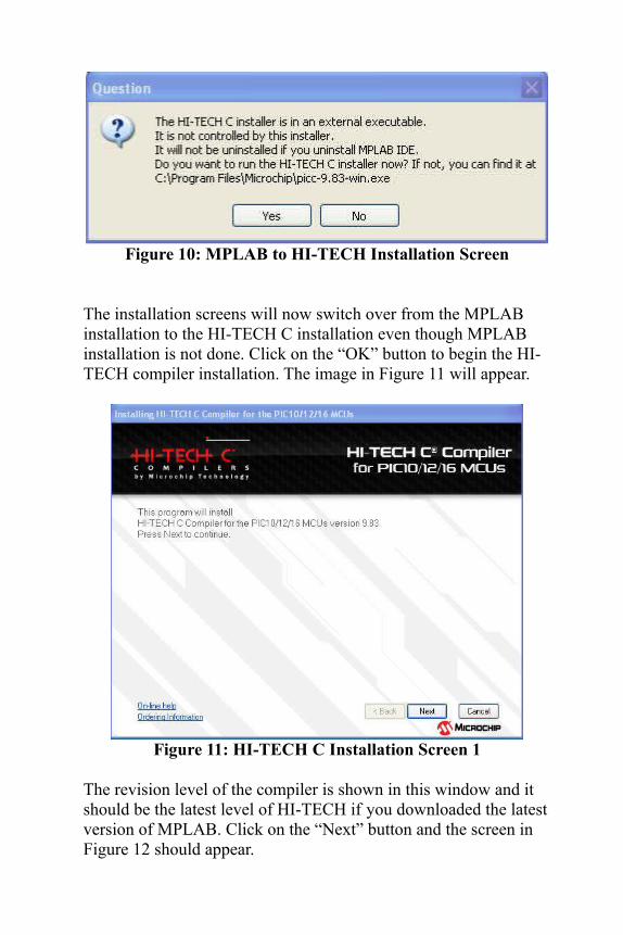
Figure 10: MPLAB to HI-TECH Installation Screen
The installation screens will now switch over from the MPLAB installation to the HI-TECH C installation even though MPLAB installation is not done. Click on the “OK” button to begin the HI-TECH compiler installation. The image in Figure 11 will appear.
Figure 11: HI-TECH C Installation Screen 1
The revision level of the compiler is shown in this window and it should be the latest level of HI-TECH if you downloaded the latest version of MPLAB. Click on the “Next” button and the screen in Figure 12 should appear.

Figure 12: HI-TECH Installation Screen 2
The Figure 12 screen asks for you to accept their license agreement. Read it over and click “Next” to accept.
Figure 13: HI-TECH Installation Screen 3
Notice that the next screen (Figure 13) shows the installation path C:\Program Files\HI-TECH Software\PICC\ 9.83. We will need this later when we setup our first project so I suggest you write this down. Click on “Next” to get the fourth screen shown in Figure 14.
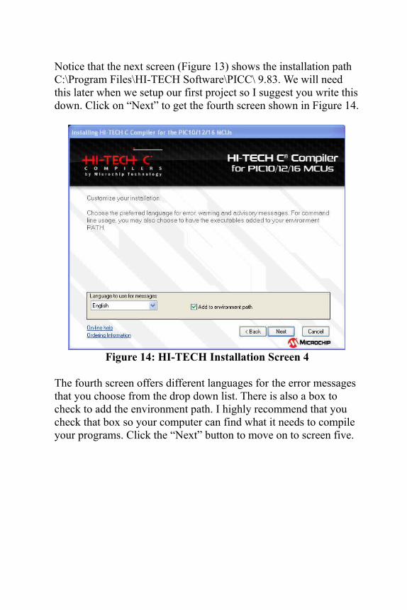
Figure 14: HI-TECH Installation Screen 4
The fourth screen offers different languages for the error messages that you choose from the drop down list. There is also a box to check to add the environment path. I highly recommend that you check that box so your computer can find what it needs to compile your programs. Click the “Next” button to move on to screen five.

Figure 15: HI-TECH Installation Screen 5
Figure 15 shows the installation happening. Wait until it’s done and then Figure 16 will appear. Just click on the “Finish” button and the installation will jump back to the MPLAB installation.
Figure 16: Final HI-TECH Installation Screen

The next screen will be the final MPLAB installation screen shown in Figure 17. It may ask if you want to restart your computer and I suggest you click on the “Yes” choice and let your computer reboot with all this new software installed.
Figure 17: MPLAB Final Installation Screen
SimpleC Library The SimpleC library is a separate C file titled simplec1.1.c that you include in your MPLAB project. Sample projects at the end of this manual show you how to use the SimpleC library. A header file simplec1.1.h also needs to be included in your main C language file at the top with the format shown below.
#include “simplec1.1.h”
You’ll also see this in the sample projects in the next sections. The full list of SimpleC library functions is in a separate SimpleC Library document on the CD. It’s best to copy the
simplec11.c and simplec1.1.h files to a known directory on your computer because you will need to find them later on when you
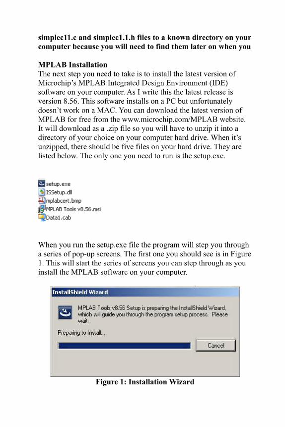
MPLAB InstallationThe next step you need to take is to install the latest version of Microchip’s MPLAB Integrated Design Environment (IDE) software on your computer. As I write this the latest release is version 8.56. This software installs on a PC but unfortunately doesn’t work on a MAC. You can download the latest version of MPLAB for free from the www.microchip.com/MPLAB website. It will download as a .zip file so you will have to unzip it into a directory of your choice on your computer hard drive. When it’s unzipped, there should be five files on your hard drive. They are listed below. The only one you need to run is the setup.exe.
When you run the setup.exe file the program will step you through a series of pop-up screens. The first one you should see is in Figure 1. This will start the series of screens you can step through as you install the MPLAB software on your computer.
Figure 1: Installation Wizard

Next the screen in Figure 2 should appear automatically. Click on the “Next” button to move on but as the screen states, it’s highly recommend that you close all applications you may have running so you don’t get any conflicts. At the end of the installation you will have to restart your computer anyway so why not just shut everything down before you install. Figure 3 shows the next screen.
Figure 2: MPLAB Installation Step 1

Figure 3: MPLAB Installation Step 2
Read over the license agreement and if you accept it, click in the “I accept” radio button and then the “Next” button to get to the next screen shown in Figure 4.
Figure 4: MPLAB Installation Step 3
If you really need to save hard drive space, you may want to select the “Custom” installation but I recommend the “Complete”

installation. This will put all the Microchip tools and files on your hard drive so you aren’t looking for them later. Click on “Next” to get to the next screen shown in Figure 5.
Figure 5: MPLAB Installation Step 4
Step 4 will offer you a path to install MPLAB. It is tempting to put this in another location but I highly recommend you let this install at the default directory. All Microchip documentation that refers to the path will reference this location. Click next for Step 5 shown in Figure 6.
Figure 6: MPLAB Installation Step 5

Step 5 wants you to accept the terms of installing MAESTRO which is a setup feature option installed with MPLAB. We won’t use this feature but it is suggested you allow MPLAB to install this. Click on the “Next” button to get the Step 6 screen shown in Figure 7.
Figure 7: MPLAB Installation Step 6
Step 6 is more legal stuff asking to accept the C32 license. Again it’s recommend to accept. Click on “Next” to get to step 7 shown in Figure 8.

Figure 8: MPLAB Installation Step 7
This screen shows what will be installed. Click next to move on.
Figure 9: MPLAB Installation Step 8
The installation process will get real slow now as all the files are loaded on your computer. I captured just one of the screens in this process but you will see the progress bar grow as different sections are installed. This will continue for a little while so grab a coffee and relax.
HI_TECH PICC-Lite InstallationWhen all the files have been loaded, MPLAB installation will not end. Instead it will take a twist and offer to automatically install the HI-TECH© PICC-Lite compiler. This is what we want so click on the “OK” button to let it happen.

Figure 10: MPLAB to HI-TECH Installation Screen
The installation screens will now switch over from the MPLAB installation to the PICC-Lite installation even though MPLAB installation is not done. Click on the “OK” button to begin the HI-TECH compiler installation. The image in Figure 11 will appear.
Figure 11: HI-TECH C Installation Screen 1
The revision level of the compiler is shown in this window and it should be the latest level of HI-TECH if you downloaded the latest version of MPLAB. Click on the “Next” button and the screen in Figure 12 should appear.
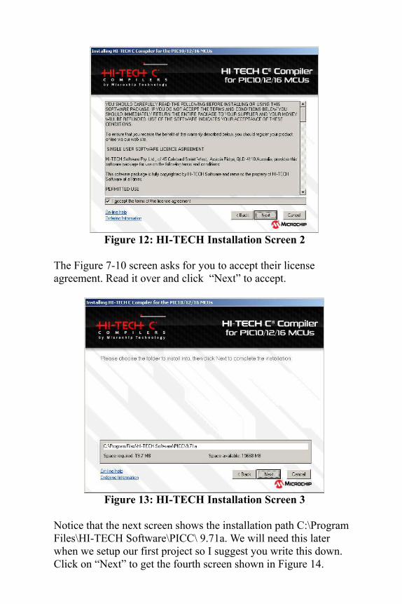
Figure 12: HI-TECH Installation Screen 2
The Figure 7-10 screen asks for you to accept their license agreement. Read it over and click “Next” to accept.
Figure 13: HI-TECH Installation Screen 3
Notice that the next screen shows the installation path C:\Program Files\HI-TECH Software\PICC\ 9.71a. We will need this later when we setup our first project so I suggest you write this down. Click on “Next” to get the fourth screen shown in Figure 14.
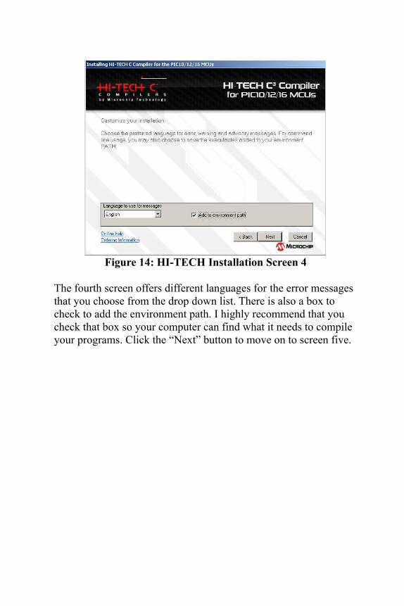
Figure 14: HI-TECH Installation Screen 4
The fourth screen offers different languages for the error messages that you choose from the drop down list. There is also a box to check to add the environment path. I highly recommend that you check that box so your computer can find what it needs to compile your programs. Click the “Next” button to move on to screen five.

Figure 15: HI-TECH Installation Screen 5
Figure 15 shows the installation happening. Wait until it’s done and then Figure 16 will appear. Just click on the “Finish” button and the installation will jump back to the MPLAB installation.
Figure 16: Final HI-TECH Installation Screen

The next screen will be the final MPLAB installation screen shown in Figure 17. It will ask if you want to restart your computer and I suggest you click on the “Yes” choice and let your computer reboot with all this new software installed.
Figure 17: MPLAB Final Installation Screen
SimpleC Library The SimpleC library is a separate C file titled simplec1.1.c that you include in your MPLAB project. Sample projects at the end of this manual show you how to use the SimpleC library. A header file simplec1.1.h also needs to be included in your main C language file at the top with the format shown below.
#include “simplec1.1.h”
You’ll also see this in the sample projects in the next sections. The full list of SimpleC library functions is in a separate SimpleC Library document on the CD. It’s best to copy the simplec11.c and simplec1.1.h files to a known directory on your computer because you will need to find them later on when you build any of your projects with the CHIPINO.

Please Note: HI-TECH Version 9.81+Microchip recently updated the HI-TECH C compiler for 10F, 12F and 16 parts to version 9.81 and later and in this update they made a change that affects all the code in the Beginner's Guide to Embedded C books. They made a change to the register names to match the data sheet exactly. These definitions are contained in the various header files for the different microchip PICs. This is a good move overall but for those using programs written for the previous versions, 9.80 and earlier, this causes many errors to appear when the project is compiled. There is a simple fix thankfully. By adding the one line below at the top of the program (it has to be the first line) all the original header files are used instead of the new definition files. If you have experienced this issue, this is the fix. We've already corrected the files included with the SimpleC download.
#define _LEGACY_HEADERS
For example here is how its used in the book Beginner's Guide to Embedded C.
#define _LEGACY_HEADERS // Define required for compiler version 9.81 and later #include <htc.h> // Include HITECH CC header file
//Internal clock, Watchdog off, MCLR off, Code Unprotected__CONFIG (INTIO & WDTDIS & PWRTDIS & MCLRDIS & BORDIS & UNPROTECT & IESODIS & FCMDIS );
main(){ ANSEL = 0; // Intialize A/D ports off CM1CON0 = 0; // Initialize Comparator 1 off CM2CON0 = 0; // Initialize Comparator 2 off PORTC = 0x00; //Clear PortC port TRISC = 0x00; //All PortC I/O outputswhile(1==1) //loop forever{RC0 = 1; // Turn on RC0 LED}//End while}//end main
CHIPINO Module Setup

The CHIPINO is a development board (shown in Figure 1) designed to make using the Microchip PIC microcontrollers much easier. The CHIPINO can be programmed with many different Microchip PIC programmers, which I explain more about in a few sections forward. The CHIPINO is designed to accept many different 28 pin Microchip PIC microcontrollers with a focus on the PIC16F886. The module has many built in features:
1) An In-Circuit Serial Programming (ICSP) port for connecting to the PIC programmer that also allows debugging for advanced users and can power the CHIPINO with up to 75 ma.
2) A 2.1mm center positive power port for external power with an on/off switch.
3) A 5v large regulator for up to 500 ma.4) A 16 Mhz crytal oscillator to run the 28 pin
microcontroller.5) A master reset switch.6) An LED to indicate power on or off.7) A full input/output header rail system that matches the
footprint of the popular Arduino module so you can plug in many Arduino Shields and use them.
8) A 3.3v regulator to supply 100 ma of 3.3v power for those applications that need a lower voltage.

Figure 1-2: CHIPINO Module
You can use any Microchip PIC programmer that supports the 6-pin header with the CHIPINO module. The most popular is the Microchip PICkit 2. Microchip also open sourced the schematics and software for the PICkit 2 programmer. The CHIPINO Starter Kits include a PICkit 2 or PICkit 3 programmer.
Figure 2: PICkit Programmers

The PICkit programmer has a 6 pin header. Connect the 6 pin header to the 6 pin header on the CHIPINO by lining up the arrows on the board and the programmer. Connect the other end of the programmer into your PC USB port with the USB cable and the computer should recognize and enable the programmer quickly.
The PICkit programmer can power the CHIPINO board with 5v from the programming connector. The limit is 75 milliamps. If you need more than that you will have to connect a 9v supply to the external power port. Slide the switch to the on position to use the external power.
To build the circuits in the coming project section, carefully plug the CHIPINO proto-shield into the CHIPINO module to give you a breadboard area to build your circuits. The proto-shield pins are very thin so be careful not to bend the pins.
You are ready to start your first CHIPINO project.

Project 1 Digital Output –Flash an LED
This first project will flash an LED connected to pin 8 (RB0) pin. This is a simple project but will allow you to prove everything is installed correctly and working properly.
Project Construction1) Plug the LED and 1k resistor into the breadboard similar to
the picture below. The flat side of the LED (Cathode) also has the shorter lead. This lead should line up with the ground side of the proto-shield connector.
2) The 1k resistor should connect to the long LED lead (Anode) through the same channel of the breadboard.
3) Now connect pin 8 to the resistor with a wire jumper.4) Connect the GND pin to the LED with a jumper wire.
The project is ready to be programmed.
Creating the SoftwareThe software is already pre-written and in the samples directory of the CD. To get started we have to use the project wizard in MPLAB to create the software. You should have the MPLAB icon
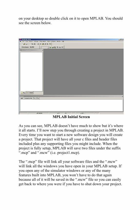
on your desktop so double click on it to open MPLAB. You should see the screen below.
MPLAB Initial Screen
As you can see, MPLAB doesn’t have much to show but it’s where it all starts. I’ll now step you through creating a project in MPLAB. Every time you want to start a new software design you will create a project. That project will have all your c files and header files included plus any supporting files you might include. When the project is fully setup, MPLAB will save two files under the suffix “.mcp” and “.mcw” (i.e. project1.mcp).
The “.mcp” file will link all your software files and the “.mcw” will link all the windows you have open in your MPLAB setup. If you open any of the simulator windows or any of the many features built into MPLAB, you won’t have to do that again because all of it will be saved in the “.mcw” file so you can easily get back to where you were if you have to shut down your project.

To make creating a project easier, MPLAB has a “wizard” feature that will step you through creating a project. We’ll do that here with the first project so you see how to set a project up using the wizard. Figure 19 shows the first step.
Figure 19: MPLAB Project Wizard Selection
Click on the “Project” menu option in the MPLAB screen to get to the Project Wizard option. It will be the first item to select. Click on that Project Wizard sub-menu option to open the window shown in Figure 20.

Figure 20: MPLAB Project Wizard Screen 1
You should now have a separate window within the MPLAB environment that welcomes you to the project wizard. Click on the “Next” button to move forward.

Figure 21: MPLAB Project Wizard Screen 2
The step is to pick the microcontroller you plan to design with as shown in Figure 21. Select the proper part from the long list of choices and click the “Next” button to get to the Figure 22 screen.
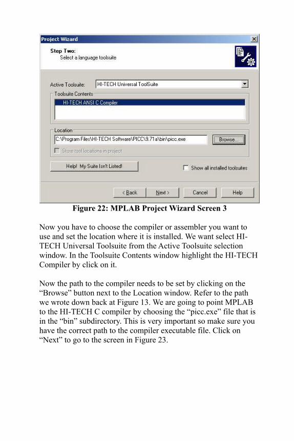
Figure 22: MPLAB Project Wizard Screen 3
Now you have to choose the compiler or assembler you want to use and set the location where it is installed. We want select HI-TECH Universal Toolsuite from the Active Toolsuite selection window. In the Toolsuite Contents window highlight the HI-TECH Compiler by click on it.
Now the path to the compiler needs to be set by clicking on the “Browse” button next to the Location window. Refer to the path we wrote down back at Figure 13. We are going to point MPLAB to the HI-TECH C compiler by choosing the “picc.exe” file that is in the “bin” subdirectory. This is very important so make sure you have the correct path to the compiler executable file. Click on “Next” to go to the screen in Figure 23.

Figure 23: MPLAB Project Wizard Screen 4
The next screen is where you create the project name that will also be the prefix of your “.mcp” and “.mcw” files. Click on the “Browse” button to choose where you want the file to be located on your hard drive. Try to choose a path close to the root directory to keep the path name short. Click “Next” when you are ready to get the screen shown in Figure 24.
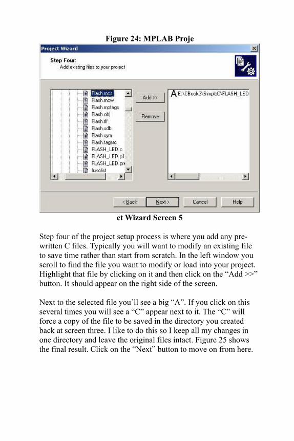
Figure 24: MPLAB Proje
ct Wizard Screen 5
Step four of the project setup process is where you add any pre-written C files. Typically you will want to modify an existing file to save time rather than start from scratch. In the left window you scroll to find the file you want to modify or load into your project. Highlight that file by clicking on it and then click on the “Add >>” button. It should appear on the right side of the screen.
Next to the selected file you’ll see a big “A”. If you click on this several times you will see a “C” appear next to it. The “C” will force a copy of the file to be saved in the directory you created back at screen three. I like to do this so I keep all my changes in one directory and leave the original files intact. Figure 25 shows the final result. Click on the “Next” button to move on from here.

Figure 25: MPLAB Project Wizard Screen 6
SimpleC Setup (optional):If you don’t want to use the SimpleC library then you can click next to move on. If you do want to use the SimpleC library then you need to add the simplec1.1h and simplec1.1.c files to the project. On the left side of the step four screen, locate the simplec files and add them to the right side. Click on the A until it changes to C for both simplec files. This will save a copy of those files to the same directory as your project while leaving the original simplec files untouched.
The screen in Figure 26 is the final screen in the project setup. When you get here you have successfully created your first project. Just click finish and the MPLAB window will be the next screen you see as in Figure 27.

Figure 26: Final MPLAB Project Wizard Screen
The project screen shown in Figure 27 may initially be blank so so to show the project and output windows click on the View>Project option from the top menu. You will see a check mark appear and the window will also pop up typically in the upper left corner with your project files shown.

Figure 27: MPLAB Project Screens
Click on the View>Output option in the menu and the output window will appear typically at the bottom of the screen. The project window will show the C file you selected earlier. Double click on the C file in your project and the MPLAB Editor window should open up with the code listing displayed. Figure 28 shows the editor screen open with the program file open.

Figure 28: MPLAB Editor Window
You would typically modify the file in the editor window to get the program written the way you want. When the file modifications are complete then you are ready to compile it using the HI-TECH compiler. The MPLAB makes this easy by a simple click of the “Build All” button located at the top of the screen as shown in Figure 29.
Figure 29: MPLAB Project Build All
If your code has any errors this is the step where they show up. The results from the “Build All” will be displayed in the output window. I did it for my sample project and the build was successful as shown in Figure 30.

Figure 30: MPLAB Build All Success
Once the build is successful we want to load the code into the PIC16F886 and we do that with either the Microchip PICkit 2 or PICkit 3 Programmer. Click on the Programmer>Select Programmer>PICkit 2 menu selection to enable the PICkit 2 as shown in Figure 31.
Figure 31: Launching PICkit 2 Programmer
The PICkit 2 will respond to signals sent from MPLAB and a status message will be displayed in the PICkit 2 window which is just another tab on the output window as seen in 32.

Figure 32: PICkit 2 Programmer Ready
The upper corner of the MPLAB window will show the control buttons for the PICkit 2 programmer. The first one with a yellow color and a curved arrow pointing downward is the programming button as seen in Figure 7-30. Make sure the PIC16F886 is in the development board the proper way and press the programming button.
Figure 33: PICkit 2 Programmer Control Buttons
The output window will show the results of the programming process which includes erasing the part, then programming it. It’s followed by a verification step to compare what is actually in the chip after programming with what MPLAB sent to the programmer. If they match the programming was successful and the output window will show that the PICkit 2 is ready to do it again. Figure 34 shows that result.

Figure 34: PICkit 2 Successfully Programmed the PIC16F886
That is all there is to setting up the development tools to start writing C programs for the PIC16F886 in the Chipino.

Project 2 Digital Input – Sense a Switch Press
This project will show how to use a digital input to sense a switch press of a normally open switch. When pressed, the LED will light up.
Project Construction1) Plug the LED and 1k resistor into the breadboard similar to
the picture below. The flat side of the LED (Cathode) also has the shorter lead. This lead should line up with the ground side of the proto-shield connector.
2) The 1k resistor should connect to the long LED lead (Anode) through the same channel of the breadboard.
3) Now connect pin 8 to the resistor with a wire jumper.4) Connect the GND pin to the LED with a jumper wire.5) Plug the switch into the breadboard as shown in the picture.6) Plug the 10k resistor inline with one side of the switch.7) Connect a wire from the end of the resistor to the 5v port.8) Connect the other side of the resistor and switch connection
to pin 7 (C0).9) Use two wires to connect the other side of the switch to one
of the GND pins next to the 5v.
The project is ready to be programmed.

Creating the SoftwareFollow the same steps as the previous project to create a new project in MPLAB using the project wizard. The only difference is this time load the “switch.c” file instead of the LED file.When complete, click on the build icon and if the build is successful, launch the PICkit to program the module.
The LED should be off and when you press the switch, the LED should light up.

Project 3 Analog Input – Sense Potentiometer
This project will show how to use an analog input to sense a potentiometer position. When the potentiometer is turned past a certain point, the LED will light. When rotated the opposite way the LED will go off.
Project Construction1) Plug the LED and 1k resistor into the breadboard similar to
the picture below. The flat side of the LED (Cathode) also has the shorter lead. This lead should line up with the ground side of the proto-shield connector.
2) The 1k resistor should connect to the long LED lead (Anode) through the same channel of the breadboard.
3) Now connect pin 8 to the resistor with a wire jumper.4) Connect the GND pin to the LED with a jumper wire.5) Plug the potentiometer into the breadboard as shown in the
picture.6) Connect a wire from the left side of the potentiometer to
the 5v port.7) Connect the left side of the potentiometer to one of the
GND pins next to the 5v8) Connect the center of the potentiometer to the Analog pin 0
(A0).
The project is ready to be programmed.

Creating the SoftwareFollow the same steps as the previous projects to create a new project in MPLAB using the project wizard. The only difference is this time load the “ADCIN.c” file instead of the LED file.When complete, click on the build icon and if the build is successful, launch the PICkit to program the module.
The LED should be off and when you turn the potentiometer to the left and the LED should light up when you turn to the right.

ConclusionYou are ready to start programming the CHIPINO with your own creations. You can also program the CHIPINO is pure C code using the HI-TECH compiler. We recommend you check out the books Beginner’s Guide to Embedded C Programming by Chuck Hellebuyck (www.elproducts.com) for more details on how to use the HI-TECH C compiler.