Chip-Set TP-UART 'd' - Siemens Global Website · GAMMA instabus OEM- Product Catalogue Release:...
27
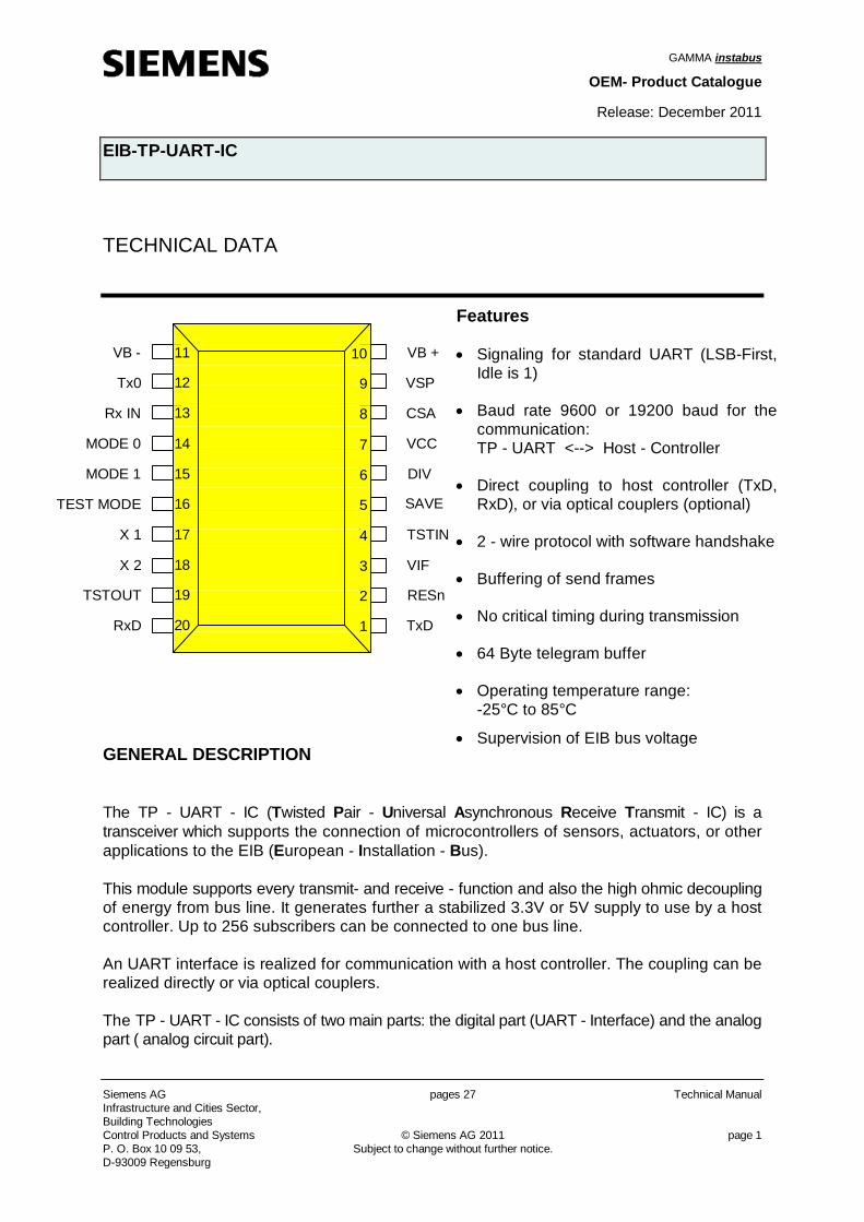
GAMMA instabus OEM- Product Catalogue Release: December 2011 EIB-TP-UART-IC Siemens AG pages 27 Technical Manual Infrastructure and Cities Sector, Building Technologies Control Products and Systems © Siemens AG 2011 page 1 P. O. Box 10 09 53, Subject to change without further notice. D-93009 Regensburg TECHNICAL DATA GENERAL DESCRIPTION The TP - UART - IC (Twisted Pair - Universal A synchronous Receive Transmit - IC) is a transceiver which supports the connection of microcontrollers of sensors, actuators, or other applications to the EIB (European - Installation - Bus). This module supports every transmit- and receive - function and also the high ohmic decoupling of energy from bus line. It generates further a stabilized 3.3V or 5V supply to use by a host controller. Up to 256 subscribers can be connected to one bus line. An UART interface is realized for communication with a host controller. The coupling can be realized directly or via optical couplers. The TP - UART - IC consists of two main parts: the digital part (UART - Interface) and the analog part ( analog circuit part). Features Signaling for standard UART (LSB-First, Idle is 1) Baud rate 9600 or 19200 baud for the communication: TP - UART <--> Host - Controller Direct coupling to host controller (TxD, RxD), or via optical couplers (optional) 2 - wire protocol with software handshake Buffering of send frames No critical timing during transmission 64 Byte telegram buffer Operating temperature range: -25°C to 85°C Supervision of EIB bus voltage VB - Tx0 Rx IN MODE 0 MODE 1 TEST MODE X 1 X 2 TSTOUT RxD 11 12 13 14 15 16 17 18 19 20 10 9 8 7 6 5 4 3 2 1 VB + VSP CSA VCC DIV SAVE TSTIN VIF RESn TxD
Transcript of Chip-Set TP-UART 'd' - Siemens Global Website · GAMMA instabus OEM- Product Catalogue Release:...
GAMMA instabus
OEM- Product Catalogue
Release: December 2011
EIB-TP-UART-IC
Siemens AG pages 27 Technical Manual Infrastructure and Cities Sector, Building Technologies Control Products and Systems © Siemens AG 2011 page 1 P. O. Box 10 09 53, Subject to change without further notice. D-93009 Regensburg
TECHNICAL DATA
GENERAL DESCRIPTION The TP - UART - IC (Twisted Pair - Universal Asynchronous Receive Transmit - IC) is a transceiver which supports the connection of microcontrollers of sensors, actuators, or other applications to the EIB (European - Installation - Bus). This module supports every transmit- and receive - function and also the high ohmic decoupling of energy from bus line. It generates further a stabilized 3.3V or 5V supply to use by a host controller. Up to 256 subscribers can be connected to one bus line. An UART interface is realized for communication with a host controller. The coupling can be realized directly or via optical couplers. The TP - UART - IC consists of two main parts: the digital part (UART - Interface) and the analog part ( analog circuit part).
Features
Signaling for standard UART (LSB-First, Idle is 1)
Baud rate 9600 or 19200 baud for the communication: TP - UART <--> Host - Controller
Direct coupling to host controller (TxD, RxD), or via optical couplers (optional)
2 - wire protocol with software handshake
Buffering of send frames
No critical timing during transmission
64 Byte telegram buffer
Operating temperature range: -25°C to 85°C
Supervision of EIB bus voltage
VB -
Tx0
Rx IN
MODE 0
MODE 1
TEST MODE
X 1
X 2
TSTOUT
RxD
11
12
13
14
15
16
17
18
19
20
10
9
8
7
6
5
4
3
2
1
VB +
VSP
CSA
VCC
DIV
SAVE
TSTIN
VIF
RESn
TxD
GAMMA instabus Release: December 2011 EIB-TP-UART-IC
Technical Manual pages 27 Siemens AG Infrastructure and Cities Sector,
Building Technologies page 2 © Siemens AG 2011 Control Products and Systems Subject to change without further notice. P. O. Box 10 09 53, D-93009 Regensburg
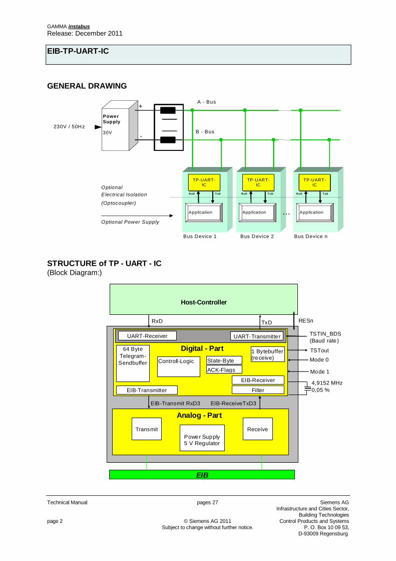
GENERAL DRAWING
PowerSupply
30V
TP-UART-IC
+
-
A - Bus
B - Bus
Bus Device 1 Bus Device 2 Bus Device n
Optional Power Supply
230V / 50Hz
OptionalElectrical Isolation
(Optocoupler)
TxDRxD TxDRxD TxDRxD
...
TP-UART-IC
TP-UART-IC
Application Applica tion Application
STRUCTURE of TP - UART - IC (Block Diagram:)
Host-Controller
EIB
Filter
1 Bytebuffer (receive)
EIB-Receiver
UART-Transmitter
64 Byte Telegram-Sendbuffer
EIB-Transmitter
TSTIN_BDS (Baud rate)
RxD TxD
EIB-Transmit RxD3 EIB-ReceiveTxD3
Digital - Part
RESn
Controll-Logic State-Byte
ACK-Flags
UART-Receiver
TSTout
Mode 0
Mode 1
4,9152 MHz 0,05 %
Analog - Part
Controll-Logic
Transmit
Receive
Power Supply 5 V Regulator
GAMMA instabus Release: December 2011
EIB-TP-UART-IC
Siemens AG pages 27 Technical Manual Infrastructure and Cities Sector, Building Technologies Control Products and Systems © Siemens AG 2011 page 3 P. O. Box 10 09 53, Subject to change without further notice. D-93009 Regensburg
1 The ANALOG - PART 1.1 General Device Specification 1.1.1 Absolute Maximum Ratings All voltages are referring to VB-. Currents are declared positive in case of flowing into pin. Symbol Parameter Min Max Unit Note
VB+ positive line voltage -0.5 45 V 1) VCC positive voltage supply (internal or external supply) -0.5 7 V 2) VIF positive external voltage supply -0.5 7 V 2)
VVSP interstate voltage (generated by on-chip regulator) -0.5 13 V 2) VTxO voltage on pin Tx0 -0.5 45 V 1)
VRxIN voltage on pin RxIN -15 45 V 1) 4)
VLV1 voltage on low voltage pins MODE0, MODE1, TSTIN, TESTMODE
-0.5 VCC +0.5 V
VLV2 voltage on low voltage pins TxD, RESn, TSTOUT, X1, X2, RxD
-0.5 VIF +0.5 V
j junction temperature 170 C
S storage temperature -65 170 C VESD max. ESD stress voltage ± 1000 V 3)
ILATCHUP static current for latchup initialization ± 50 mA Rth thermal resistance of the SOIC-20 package 58.5 71.5 K/W PV maximum power dissipation 1 W
1) During surge impulse is allowed and guaranteed by ext. elements: -20 V for 2 µsec and 65 V for 150 µsec 2) Allowed voltage relations: (a) VCC and VVSP normal / VB+ and VIF can be 0 V (b) VVSP normal / VCC , VB+ and VIF can be 0 V (c) VIF normal / VCC , VB+ and VVSP can be 0 V The combination: VCC normal and VVSP = 0 V is not allowed! 3) Human body model: 100 pF, 1.5 k 4) Dynamic via CREC= 47 nF in case of switching-on the bus voltage
1.1.2 Recommended Operating Conditions Symbol Parameter Min Max Unit Note
VB+ positive line voltage 20 33 V 1) VCC positive voltage supply for external supply
(digital test modes with SHB = 0) 4.75 5.25 V
VIF positive external supply voltage 3.0 5.25 V
amb ambient temperature -25 85 C fclk clock frequency (external quartz) 4.9152 MHz
1) DC voltage of bus, with signal and compensation pulse 11 V ... 45 V
GAMMA instabus Release: December 2011
EIB-TP-UART-IC
Technical Manual pages 27 Siemens AG Infrastructure and Cities Sector,
Building Technologies page 4 © Siemens AG 2011 Control Products and Systems Subject to change without further notice. P. O. Box 10 09 53, D-93009 Regensburg
1.1.3 Humidity Level The valid susceptibility against humidity is described by JEDEC JESD22-A112, table 1, level 5. 1.2 DC and AC Characteristics The following parameters are valid in the ambient temperature range amb = -25 C to 85 C and for bus voltage VB+ = 20 to 33 V if it is not otherwise declared. When the bus voltage is lower than 20 V and no RESET is active then the normal functionality must be fulfilled, but the parameters may be outside the limits. 1.2.1 Bus Pins VB+ and VB- (Pins 10, 11) Via these pins the ASIC is connected to the bus line. VB- represents the reference potential.
Symbol Parameter Min Max Unit Note VVB+ positive line voltage -0.5 45 V 1) Inormal current consumption in analog mode (without clock) 1 mA Inormal current consumption in normal mode (with clock) 1.6 mA 4,9152 MHz
1) during surge impulse is allowed and guaranteed by ext. Elements: -20 V for 2 µs and 65 V for 150 µs 1.2.2 Buffer Voltage VSP (Pin 9) The ASIC delivers a supply voltage of 5 volts to external loads. In order to prevent a rapid change of bus current as a result of a rapid change of the load an external capacitor at the pin VSP is used for energy storage. The static voltage is adjusted to app. 8,8 V (8,2 ...9,2) by an internal regulator.
Symbol Parameter Min Max Unit Note VVSP Energy buffer voltage 5.76 13 V 1) CVSP External storage capacitor 80 µF 2)
1) due to the limited current changing rate an overshoot of VVSP after load change may occur 2) recommended 100 F; must be larger than the capacitor at VCC
1.2.3 Current Controlling Pin CSA (Pin 8) An external capacitor at this pin prevents a quick change of ASIC current in case of quick changing bus voltage VB+ or load current IVCC. The ASIC current changes with a rate of max. 0,5 mA/ms (CCSA = 47 nF).
Symbol Parameter Min Max Unit Note CCR max. current changing rate (ext. Start, CCSA = 47 nF) 0.2 0.5 mA/ms 1)
1)tolerance of capacitor CCSA = 47nF/50V +/- 5%
GAMMA instabus Release: December 2011
EIB-TP-UART-IC
Siemens AG pages 27 Technical Manual Infrastructure and Cities Sector, Building Technologies Control Products and Systems © Siemens AG 2011 page 5 P. O. Box 10 09 53, Subject to change without further notice. D-93009 Regensburg
1.2.4 Supply Pin VCC (Pin 7) The pin VCC delivers the internal generated voltage supply to external loads. An external short-circuit from the VCC pin to GND will not cause a destruction of the ASIC.
Symbol Parameter Min Max Unit Note VVCC Voltage supply (generated by the ASIC or external
source in case of digital test modes) 4.75 5.25 V 1)
CVCC External storage capacitor 6,8 10 µF +/-20 % IVCC External load at VCC 10 mA 2)
1) VB+ 11 V 2) If there is a current leap ILeap with a slope greater than 1 mA/ms the following formulas have to be
applied: IStat is the static current, i.e. slope not greater than 1 mA/ms IStat 3 mA; ILeap (3 mA – IStat) + 5 mA 3mA < IStat 5 mA; ILeap 8 mA - IStat IStat > 5 mA; ILeap 3 mA
1.2.5 Receive Pin RxIN (Pin 13) The Receive Pin RxIN is coupled to the EIB bus by an external capacitor. Symbol Parameter Min Max Unit Note
CREC external coupling capacitor 44.5 49.5 nF typ.47 nF1)
1)external capacitor 47 nF/50V 5% 1.2.6 Transmit Pin TxO (Pin 12) The transmit pin is connected to EIB via external resistor of typ. 68 /1W (see Typical Application Circuits). Symbol Parameter Min Max Unit Note VTRANS transmit voltage -6 -9 V 1)
1) related to VB+
GAMMA instabus Release: December 2011
EIB-TP-UART-IC
Technical Manual pages 27 Siemens AG Infrastructure and Cities Sector,
Building Technologies page 6 © Siemens AG 2011 Control Products and Systems Subject to change without further notice. P. O. Box 10 09 53, D-93009 Regensburg
1.2.7 Supply Pin VIF (Pin 3) The Pin VIF is used as supply voltage for the pins TxD, RxD, RESn, TSTOUT, X1, X2 and determines their high input or output level.
Symbol Parameter Min Max Unit Note VIF external supply voltage for interface 3 5.5 V 1) CVIF external storage capacitor 10 nF 2)
1) Typical supply voltages: 3.3 V or 5 V 2) Recommended
1.2.8 Oscillator Pins X1 and X2 (Pins 17, 18) The oscillator pins X1 and X2 are used to connect directly a quartz of 4.9152 MHz without additional external capacitors. These pins are ESD protected to VB - and VIF.
Symbol Parameter Min Max Unit Note VX1/2 Oscillator voltage at X1 and X2 -0.5 VIF + 0.5 V VIL Voltage range for input low level 0 0.25 * VIF VIH Voltage range for input high level 0.75 * VIF 1.0 * VIF fclk Clock frequency 2,4576 4,9152 MHz 1)
1) 4,9152 MHz (DIV = VCC) or 2.4576 MHz (DIV = VB -); Tolerance: 0,05 %; no other clock frequencies Operation Mode
X1 X2
Normal Mode with external Clock
Clock open
Analog Mode VB- open 1.2.9 Internal Clock Divider Pin DIV (Pin 6) This input pin activates an internal 2:1 clock divider. If a 4.9152 MHz clock is used (quartz or external clock) then pin DIV must be connected to VCC. If an 2.4576 MHz clock is used (only external clock) then this pin must be connected to VB -. Symbol Parameter Min Max Unit Note VIL voltage range for input low level 0 0.2 * VCC VIH voltage range for input high level 0.8 * VCC 1.0 * VCC
1.2.10 Interface Pin RxD (Pin 20) The UART interface input pin RxD receives the information from host controller to control the transmitter of the ASIC. This pin is an input pin with pull-down resistor. The switching levels are derived from external voltage supply VIF. This pin is ESD protected to VB- and VIF.
GAMMA instabus Release: December 2011
EIB-TP-UART-IC
Siemens AG pages 27 Technical Manual Infrastructure and Cities Sector, Building Technologies Control Products and Systems © Siemens AG 2011 page 7 P. O. Box 10 09 53, Subject to change without further notice. D-93009 Regensburg
In normal mode: RxD = LOW RxD3 = HIGH transmitter switches on In analog mode: RxD = HIGH RxD3 = HIGH transmitter switches on
Symbol Parameter Min Max Unit Note VIL voltage range for input low level 0 0.2 * VIF
VICH voltage range for input high level 0.8 * VIF 1.0 * VIF Vhyst hysteresis for switching level 0.1 * VIF 0.4 * VIF 1)
RPullDown value of internal pull-down resistor 150 450 k typ.220 k 1) switching level appr. VIF/2, i.e. VIF/2 Vhyst/2
1.2.11 Interface Pin TxD (Pin 1) The UART interface output pin TxD transmits the information to host controller. The high output level is derived from external voltage supply VIF. This pin is ESD protected to VB- and VIF. In normal mode: LOW pulse at EIB bus TxD3 = HIGH TxD = LOW In analog mode: LOW pulse at EIB bus TxD3 = HIGH TxD = HIGH
Symbol Parameter Min Max Unit Note VOH output voltage high VIF - 0.8 V IOH = -5 mA VOL output voltage low 0.5 V IOL = 5 mA tr, tf rise time, fall time (10 % 90 %) 100 ns CL = 150 pF
1.2.12 Reset Pin RESn (Pin 2) This pin is an I / O pin with internal pull - up resistor to VIF. In case of a reset the reset pin RESn delivers an active LOW signal to external host controller. The output driver is realized as open drain (NMOS - transistor). The reset state RESn = LOW can be caused by an internal RESET or by an external RESET due to forcing an active LOW to the pin RESn. The switching levels are derived from external voltage supply VIF. This pin is ESD protected to VB - and VIF. Symbol Parameter Min Max Unit Note RPullUp value of internal pull-up resistor to VIF 10 25 k
VRESmax maximum voltage at RES pin VIF + 0.5 V VIL voltage range for input low level 0 0.2 * VIF VIH voltage range for input high level 0.8 * VIF 1.0 * VIF
Vhyst hysteresis for switching level 0.1 * VIF 0.4 * VIF 1) VOL output low voltage at 1V <= VCC < 4 V, IOL = 1 mA 0.2 V VOL output low voltage at VCC <= 1V, VIF > 3 V,
IOL = 1 mA 0.2 V
VOL output low voltage at VCC >= 4 V, IOL = 3 mA 0.4 V 1) Switching level appr. VIF/2, i.e. VIF/2 Vhyst/2
GAMMA instabus Release: December 2011
EIB-TP-UART-IC
Technical Manual pages 27 Siemens AG Infrastructure and Cities Sector,
Building Technologies page 8 © Siemens AG 2011 Control Products and Systems Subject to change without further notice. P. O. Box 10 09 53, D-93009 Regensburg
1.2.13 Save PIN SAVE (Pin 5) This pin is an NMOS open drain output with internal pullup resistor to VIF. In case of break-down of the bus voltage for more than typ. 1.5 ms (save condition) this pin delivers an active LOW signal to external host electronic. This pin is ESD protected to VB- and VIF. Symbol Parameter Min Max Unit Note
RPullUp Value of internal pull-up resistor to VIF 10 25 k Vmax maximum voltage at SAVE pin VIF + 0.5 V VOL Output LOW voltage at VCC >= 4V 0.4 V IOL = 3 mA tFRG2 Delay from VB+ break-down to SAVE= LOW 0.7 3 ms Typ. 1.5 ms
In order to reach a Buffertime of at least 60 ms for VCC (IVCC 10 mA) the capacitor at VSP has to be 470 F 20 %
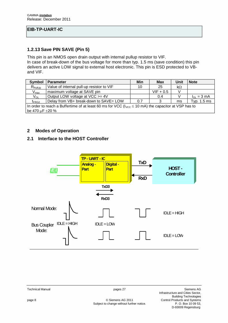
2 Modes of Operation 2.1 Interface to the HOST Controller
TxD
RxD
Normal Mode:
Bus Coupler Mode:
IDLE = HIGH
IDLE = HIGH
IDLE = LOW
EIB
TP - UART - ICAnalog -Part
Digital -Part
TxD3
RxD3
IDLE = LOW
HOST -Controller
GAMMA instabus Release: December 2011
EIB-TP-UART-IC
Siemens AG pages 27 Technical Manual Infrastructure and Cities Sector, Building Technologies Control Products and Systems © Siemens AG 2011 page 9 P. O. Box 10 09 53, Subject to change without further notice. D-93009 Regensburg
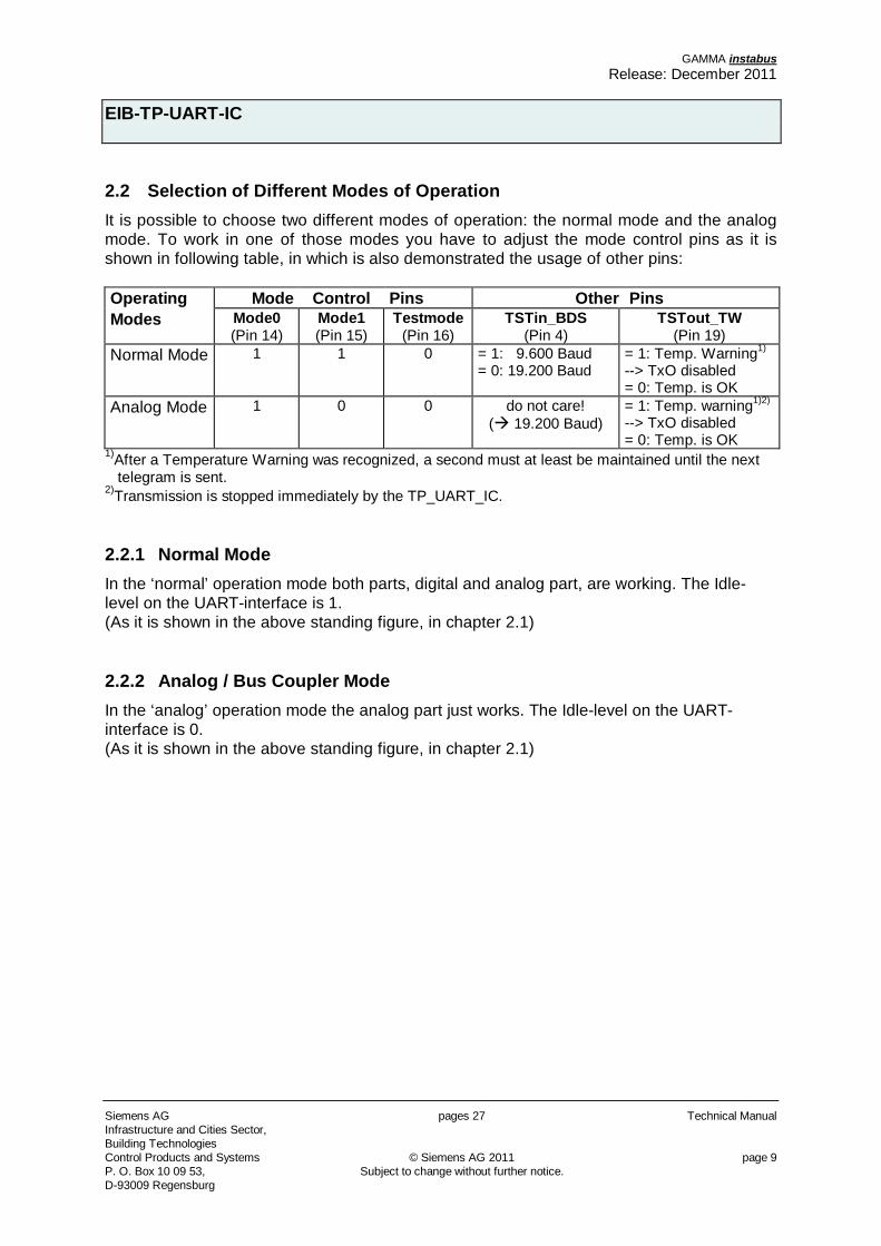
2.2 Selection of Different Modes of Operation It is possible to choose two different modes of operation: the normal mode and the analog mode. To work in one of those modes you have to adjust the mode control pins as it is shown in following table, in which is also demonstrated the usage of other pins: Operating Mode Control Pins Other Pins Modes Mode0
(Pin 14) Mode1 (Pin 15)
Testmode (Pin 16)
TSTin_BDS (Pin 4)
TSTout_TW (Pin 19)
Normal Mode 1 1 0 = 1: 9.600 Baud = 0: 19.200 Baud
= 1: Temp. Warning1)
--> TxO disabled = 0: Temp. is OK
Analog Mode 1 0 0 do not care! ( 19.200 Baud)
= 1: Temp. warning1)2)
--> TxO disabled = 0: Temp. is OK
1)After a Temperature Warning was recognized, a second must at least be maintained until the next telegram is sent. 2)Transmission is stopped immediately by the TP_UART_IC. 2.2.1 Normal Mode In the ‘normal’ operation mode both parts, digital and analog part, are working. The Idle-level on the UART-interface is 1. (As it is shown in the above standing figure, in chapter 2.1) 2.2.2 Analog / Bus Coupler Mode In the ‘analog’ operation mode the analog part just works. The Idle-level on the UART-interface is 0. (As it is shown in the above standing figure, in chapter 2.1)
GAMMA instabus Release: December 2011
EIB-TP-UART-IC
Technical Manual pages 27 Siemens AG Infrastructure and Cities Sector,
Building Technologies page 10 © Siemens AG 2011 Control Products and Systems Subject to change without further notice. P. O. Box 10 09 53, D-93009 Regensburg
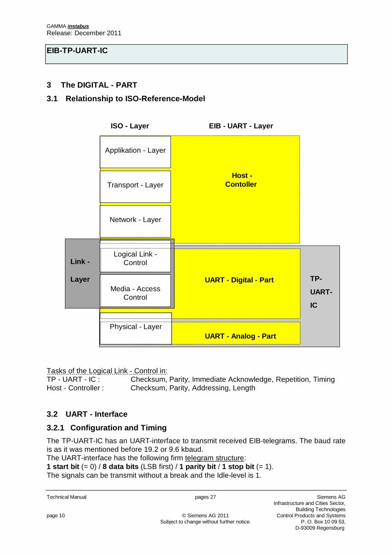
3 The DIGITAL - PART 3.1 Relationship to ISO-Reference-Model
Host - Contoller
UART - Digital - Part
UART - Analog - Part
Link -
Layer
Physical - Layer
Media - AccessControl
Logical Link -Control
Network - Layer
Transport - Layer
Applikation - Layer
ISO - Layer EIB - UART - Layer
TP-
UART-
IC
Tasks of the Logical Link - Control in: TP - UART - IC : Checksum, Parity, Immediate Acknowledge, Repetition, Timing Host - Controller : Checksum, Parity, Addressing, Length 3.2 UART - Interface 3.2.1 Configuration and Timing The TP-UART-IC has an UART-interface to transmit received EIB-telegrams. The baud rate is as it was mentioned before 19.2 or 9.6 kbaud. The UART-interface has the following firm telegram structure: 1 start bit (= 0) / 8 data bits (LSB first) / 1 parity bit / 1 stop bit (= 1). The signals can be transmit without a break and the Idle-level is 1.
GAMMA instabus Release: December 2011
EIB-TP-UART-IC
Siemens AG pages 27 Technical Manual Infrastructure and Cities Sector, Building Technologies Control Products and Systems © Siemens AG 2011 page 11 P. O. Box 10 09 53, Subject to change without further notice. D-93009 Regensburg
The parity bit of every signal is checked while down loading and faults, which can appear, are transmitted to the host controller. The check mechanism runs also while receiving of telegrams from the EIB, but here isn’t any possibility to transmit a fault to the host controller. In those cases the host controller has to recognize the parity faults in the transmitted telegrams by its own. The UART-interface works with a clock frequency of 307,2 kHz, if it is chosen 9.6 kbaud (32 sample spots per bit), or 614,4 kHz, if it is chosen 19.2 kbaud (32 sample spots per bit). 3.2.2 Resetbehavior After connecting the operating voltage the TP-UART-IC generates an active reset (level 0 V) at pin RESn. This is valid for all modes. If Normal Mode is activated the following will happen at the UART-interface. TxD will be 0 as long as there was no bus signal on the EIB for 40 Tbit (1 Tbit = 1/9600 s; Attention: The bittime of RxD/TxD depends on the adjusted baudrate at the UART-interface, for example 1 Tbit or 0,5 Tbit). This results in a complete time of 40 Tbit + 12 Tbit = 5,42 ms. Then TxD changes for 1 Tbit to 1 and following the service TPUART-Reset.Indication is transmitted. This signal behavior on TxD appears after each reset. 3.2.3 UART-Protocol Definition The protocol between TP-UART-IC and the application controller is a two wire protocol with software handshake. Each data byte transmitted to the TP-UART-IC is started with a control byte. Each data byte received on the EIB is transparently transmitted through the TP-UART-IC and is therefore started with the EIB control field. Additional Information from the TP-UART-IC is transmitted with an ESC code on the EIB control field. The host controller which is connected to the TP-UART-IC needs to detect a receive time-out of 2 to 2,5 ms to detect an end of Packet. 3.2.3.1 Services to UART The following Services are supported from the TP-UART-IC. U_Reset.request U_State.request U_Activate Busmonitor U_AckInformation (Nack, Busy, Addressed) U_L_DataStart + CTRL-Byte U_L_DataContinue (index) + Data-Byte U_L_DataEnd + Checksum U_PollingState (Slotnumber) + PollAddrHigh + PollAddrLow + State
GAMMA instabus Release: December 2011
EIB-TP-UART-IC
Technical Manual pages 27 Siemens AG Infrastructure and Cities Sector,
Building Technologies page 12 © Siemens AG 2011 Control Products and Systems Subject to change without further notice. P. O. Box 10 09 53, D-93009 Regensburg
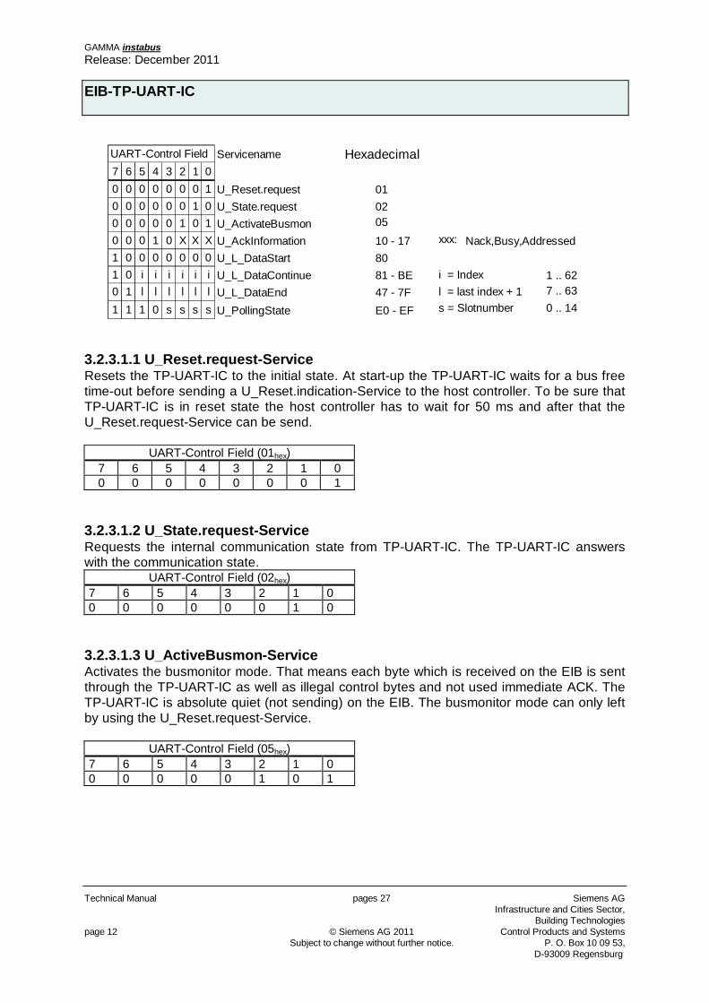
UART-Control Field Servicename Hexadecimal7 6 5 4 3 2 1 00 0 0 0 0 0 0 1 U_Reset.request 010 0 0 0 0 0 1 0 U_State.request 020 0 0 0 0 1 0 1 U_ActivateBusmon 050 0 0 1 0 X X X U_AckInformation 10 - 17 xxx: Nack,Busy,Addressed1 0 0 0 0 0 0 0 U_L_DataStart 801 0 i i i i i i U_L_DataContinue 81 - BE i = Index 1 .. 620 1 l l l l l l U_L_DataEnd 47 - 7F l = last index + 1 7 .. 63
1 1 1 0 s s s s U_PollingState E0 - EF s = Slotnumber 0 .. 14 3.2.3.1.1 U_Reset.request-Service Resets the TP-UART-IC to the initial state. At start-up the TP-UART-IC waits for a bus free time-out before sending a U_Reset.indication-Service to the host controller. To be sure that TP-UART-IC is in reset state the host controller has to wait for 50 ms and after that the U_Reset.request-Service can be send.
UART-Control Field (01hex) 7 6 5 4 3 2 1 0 0 0 0 0 0 0 0 1
3.2.3.1.2 U_State.request-Service Requests the internal communication state from TP-UART-IC. The TP-UART-IC answers with the communication state.
UART-Control Field (02hex) 7 6 5 4 3 2 1 0 0 0 0 0 0 0 1 0
3.2.3.1.3 U_ActiveBusmon-Service Activates the busmonitor mode. That means each byte which is received on the EIB is sent through the TP-UART-IC as well as illegal control bytes and not used immediate ACK. The TP-UART-IC is absolute quiet (not sending) on the EIB. The busmonitor mode can only left by using the U_Reset.request-Service.
UART-Control Field (05hex) 7 6 5 4 3 2 1 0 0 0 0 0 0 1 0 1
GAMMA instabus Release: December 2011
EIB-TP-UART-IC
Siemens AG pages 27 Technical Manual Infrastructure and Cities Sector, Building Technologies Control Products and Systems © Siemens AG 2011 page 13 P. O. Box 10 09 53, Subject to change without further notice. D-93009 Regensburg
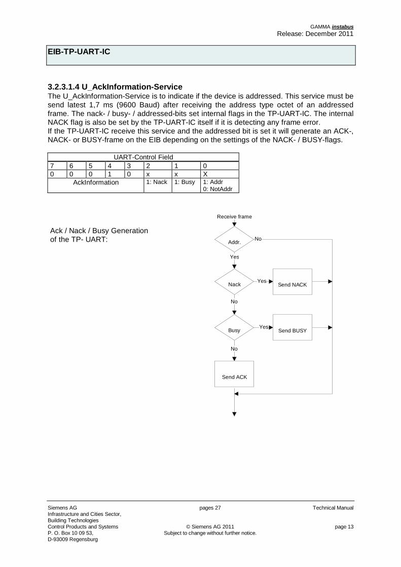
3.2.3.1.4 U_AckInformation-Service The U_AckInformation-Service is to indicate if the device is addressed. This service must be send latest 1,7 ms (9600 Baud) after receiving the address type octet of an addressed frame. The nack- / busy- / addressed-bits set internal flags in the TP-UART-IC. The internal NACK flag is also be set by the TP-UART-IC itself if it is detecting any frame error. If the TP-UART-IC receive this service and the addressed bit is set it will generate an ACK-, NACK- or BUSY-frame on the EIB depending on the settings of the NACK- / BUSY-flags.
UART-Control Field 7 6 5 4 3 2 1 0 0 0 0 1 0 x x X
AckInformation 1: Nack 1: Busy 1: Addr 0: NotAddr
Ack / Nack / Busy Generation of the TP- UART: No
Yes
Yes
No
No
Yes
Receive frame
Addr.
Nack
Busy
Send NACK
Send BUSY
Send ACK
GAMMA instabus Release: December 2011
EIB-TP-UART-IC
Technical Manual pages 27 Siemens AG Infrastructure and Cities Sector,
Building Technologies page 14 © Siemens AG 2011 Control Products and Systems Subject to change without further notice. P. O. Box 10 09 53, D-93009 Regensburg
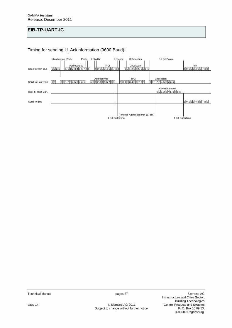
Timing for sending U_AckInformation (9600 Baud):
Interchargap (2Bit) Parity 1 Startbit 1 Stopbit 8 Datenbits 15 Bit Pause
Addresstype TPCI Checksum AckReceive from Bus 6 7 p s s 0 1 2 3 4 5 6 7 p s s 0 1 2 3 4 5 6 7 p s s 0 1 2 3 4 5 6 7 p s s 0 1 2 3 4 5 6 7 p s
Addresstype TPCI ChecksumSend to Host-Con. p s s 0 1 2 3 4 5 6 7 p s s 0 1 2 3 4 5 6 7 p s s 0 1 2 3 4 5 6 7 p s s 0 1 2 3 4 5 6 7 p s
Ack-InformationRec. fr. Host-Con. s 0 1 2 3 4 5 6 7 p s
Send to Bus s 0 1 2 3 4 5 6 7 p s
Time for Addresssearch (17 Bit)1 Bit Buffertime 1 Bit Buffertime
GAMMA instabus Release: December 2011
EIB-TP-UART-IC
Siemens AG pages 27 Technical Manual Infrastructure and Cities Sector, Building Technologies Control Products and Systems © Siemens AG 2011 page 15 P. O. Box 10 09 53, Subject to change without further notice. D-93009 Regensburg
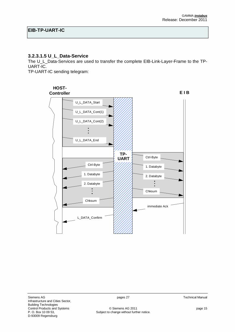
3.2.3.1.5 U_L_Data-Service The U_L_Data-Services are used to transfer the complete EIB-Link-Layer-Frame to the TP-UART-IC. TP-UART-IC sending telegram:
TP-UART
HOST-Controller E I B
U_L_DATA_Start
U_L_DATA_Cont(1)
Ctrl-Byte
1. Databyte
U_L_DATA_Cont(2)
U_L_DATA_End
2. Databyte
Chksum
L_DATA_Confirm
Ctrl-Byte
1. Databyte
2. Databyte
Chksum
immediate Ack
GAMMA instabus Release: December 2011
EIB-TP-UART-IC
Technical Manual pages 27 Siemens AG Infrastructure and Cities Sector,
Building Technologies page 16 © Siemens AG 2011 Control Products and Systems Subject to change without further notice. P. O. Box 10 09 53, D-93009 Regensburg
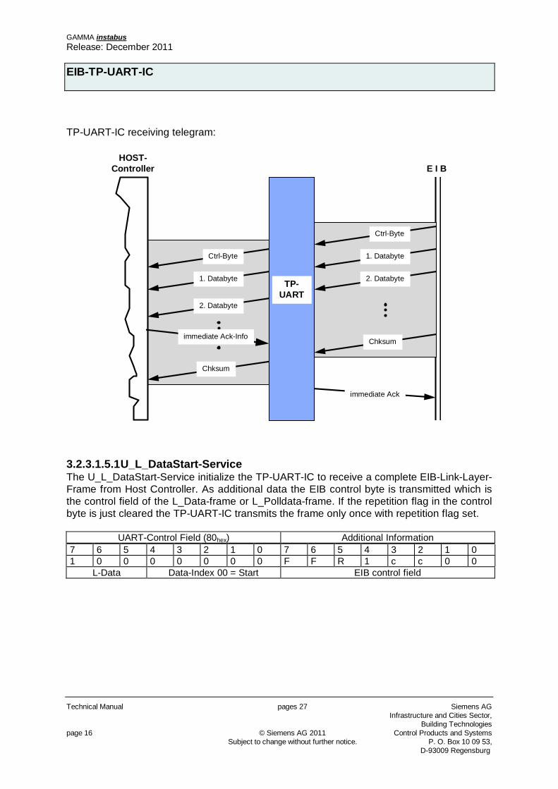
TP-UART-IC receiving telegram:
TP-UART
HOST-Controller E I B
Ctrl-Byte
1. Databyte
2. Databyte
immediate Ack
Ctrl-Byte
1. Databyte
2. Databyte
Chksum
Chksum
immediate Ack-Info
3.2.3.1.5.1 U_L_DataStart-Service The U_L_DataStart-Service initialize the TP-UART-IC to receive a complete EIB-Link-Layer-Frame from Host Controller. As additional data the EIB control byte is transmitted which is the control field of the L_Data-frame or L_Polldata-frame. If the repetition flag in the control byte is just cleared the TP-UART-IC transmits the frame only once with repetition flag set.
UART-Control Field (80hex) Additional Information 7 6 5 4 3 2 1 0 7 6 5 4 3 2 1 0 1 0 0 0 0 0 0 0 F F R 1 c c 0 0
L-Data Data-Index 00 = Start EIB control field
GAMMA instabus Release: December 2011
EIB-TP-UART-IC
Siemens AG pages 27 Technical Manual Infrastructure and Cities Sector, Building Technologies Control Products and Systems © Siemens AG 2011 page 17 P. O. Box 10 09 53, Subject to change without further notice. D-93009 Regensburg
FF = Frame Format 10 Standard Length L_DATA-EIB-Frame 00 Long L_DATA-Frames 11 Polling Frame R = Repeat-flag (on the EIB 1 = not repeated, 0 = repeated) 1 = repeat the telegram on the EIB 3 times send first time with repeat flag = 1 and repeat with repeat flag = 0 0 = don’t repeat the telegram on the EIB; send only once with repeat flag = 1 CC = Class: control field FFR1 cc00
data link frame type class repeat flag (0 = repeated)
FFR1 0000 L_DATA request system set by TP-UART-IC FFR1 1000 L_DATA request alarm set by TP-UART-IC FFR1 0100 L_DATA request high set by TP-UART-IC FFR1 1100 L_DATA request normal set by TP-UART-IC 1111 0000 L_POLLDATA request system priority = 1
3.2.3.1.5.2 U_L_DataContinue-Service The U_L_DataContinue-Service transmits one byte containing an EIB-L_Data-Frame to the TP-UART-IC. The index starts with 1 and the maximum value is 62 depending on the length of the frame. But the EIB confirms just the length of 22 Bytes.
UART-Control Field Additional Information 7 6 5 4 3 2 1 0 7 6 5 4 3 2 1 0 1 0 i i i i i i d d d d d d d d
L-Data Index EIB-Data Byte for L-Data-Frame
3.2.3.1.5.3 U_L_DataEnd-Service The U_L_DataEnd-Service marks the end of the transmission of the EIB frame. After receiving this service the TP - UART controls the checksum and in case of correctness it starts the transmission on the EIB, else the UART returns a state indication with receive- error flag is set.
UART-Control Field(40hex) Additional Information 7 6 5 4 3 2 1 0 7 6 5 4 3 2 1 0 0 1 l l l l l l c c c c c c c c
L-Data last index + 1 Checksum
GAMMA instabus Release: December 2011
EIB-TP-UART-IC
Technical Manual pages 27 Siemens AG Infrastructure and Cities Sector,
Building Technologies page 18 © Siemens AG 2011 Control Products and Systems Subject to change without further notice. P. O. Box 10 09 53, D-93009 Regensburg
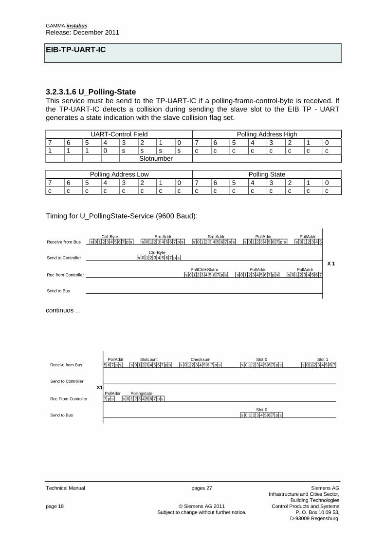
3.2.3.1.6 U_Polling-State This service must be send to the TP-UART-IC if a polling-frame-control-byte is received. If the TP-UART-IC detects a collision during sending the slave slot to the EIB TP - UART generates a state indication with the slave collision flag set.
UART-Control Field Polling Address High 7 6 5 4 3 2 1 0 7 6 5 4 3 2 1 0 1 1 1 0 s s s s c c c c c c c c Slotnumber
Polling Address Low Polling State
7 6 5 4 3 2 1 0 7 6 5 4 3 2 1 0 c c c c c c c c c c c c c c c c
Timing for U_PollingState-Service (9600 Baud):
Ctrl-Byte Src-Addr Src-Addr PollAddr PollAddrReceive from Bus s 0 1 2 3 4 5 6 7 p s s 0 1 2 3 4 5 6 7 p s s 0 1 2 3 4 5 6 7 p s s 0 1 2 3 4 5 6 7 p s s 0 1 2 3 4 5
Ctrl-ByteSend to Controller s 0 1 2 3 4 5 6 7 p s
X 1PollCtrl+Slotnr PollAddr PollAddr
Rec from Controller s 0 1 2 3 4 5 6 7 p s s 0 1 2 3 4 5 6 7 p s s 0 1 2 3 4 5 6 7
Send to Bus
continuos ...
PollAddr Slotcount Checksum Slot 0 Slot 1Receive from Bus 5 6 7 p s s 0 1 2 3 4 5 6 7 p s s 0 1 2 3 4 5 6 7 p s s 0 1 2 3 4 5 6 7 p s s 0 1 2 3 4 5 6 7
Send to ControllerX1
PollAddr PollingstateRec From Controller 7 p s s 0 1 2 3 4 5 6 7 p s
Slot 0Send to Bus s 0 1 2 3 4 5 6 7 p s
GAMMA instabus Release: December 2011
EIB-TP-UART-IC
Siemens AG pages 27 Technical Manual Infrastructure and Cities Sector, Building Technologies Control Products and Systems © Siemens AG 2011 page 19 P. O. Box 10 09 53, Subject to change without further notice. D-93009 Regensburg
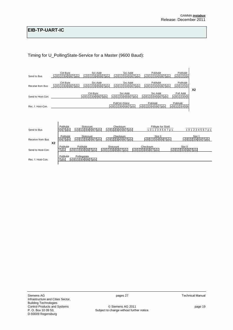
Timing for U_PollingState-Service for a Master (9600 Baud):
Ctrl-Byte Src-Addr Src-Addr PollAddr PollAddrSend to Bus s 0 1 2 3 4 5 6 7 p s s 0 1 2 3 4 5 6 7 p s s 0 1 2 3 4 5 6 7 p s s 0 1 2 3 4 5 6 7 p s s 0 1 2 3 4
Ctrl-Byte Src-Addr Src-Addr PollAddr PollAddrReceive from Bus s 0 1 2 3 4 5 6 7 p s s 0 1 2 3 4 5 6 7 p s s 0 1 2 3 4 5 6 7 p s s 0 1 2 3 4 5 6 7 p s s 0 1 2 3 4
X2Ctrl-Byte Src-Addr Src-Addr Poll Addr
Send to Host-Con. s 0 1 2 3 4 5 6 7 p s s 0 1 2 3 4 5 6 7 p s s 0 1 2 3 4 5 6 7 p s s 0 1 2 3 4 5
PollCtrl+Slotnr PollAddr PollAddrRec. f. Host-Con. s 0 1 2 3 4 5 6 7 p s s 0 1 2 3 4 5 6 7 p s s 0 1 2 3 4 5 6
PollAddr Slotcount Checksum Fillbyte for Slot0Send to Bus 5 6 7 p s s 0 1 2 3 4 5 6 7 p s s 0 1 2 3 4 5 6 7 p s s 0 1 2 3 4 5 6 7 p s s 0 1 2 3 4 5 6 7 p s
PollAddr Slotcount Checksum Slot 0 Slot 1Receive from Bus 5 6 7 p s s 0 1 2 3 4 5 6 7 p s s 0 1 2 3 4 5 6 7 p s s 0 1 2 3 4 5 6 7 p s s 0 1 2 3 4 5 6 7 p s
X2PollAddr PollAddr Slotcount Checksum Slot 0
Send to Host-Con. 7 p s s 0 1 2 3 4 5 6 7 p s s 0 1 2 3 4 5 6 7 p s s 0 1 2 3 4 5 6 7 p s s 0 1 2 3 4 5 6 7 p s
PollAddr PollingstateRec. f. Host-Con. 7 p s s 0 1 2 3 4 5 6 7 p s
GAMMA instabus Release: December 2011
EIB-TP-UART-IC
Technical Manual pages 27 Siemens AG Infrastructure and Cities Sector,
Building Technologies page 20 © Siemens AG 2011 Control Products and Systems Subject to change without further notice. P. O. Box 10 09 53, D-93009 Regensburg
3.2.3.2 Services from UART The first character of each service which is sent to the host controller is the control field. The control field contains the information about the TP - UART-Service. There are 3 types of services which can be send to the host controller: the EIB-Layer-2-Services, the Immediate-Acknowledge-Services and the special TP – UART - Services. The EIB-Layer-2-Services contain information about their class and also a flag which contains the information whether the LPDU is a repeated one, or not. The Immediate-Acknowledge-Services include information about a successful sending. The TP – UART - Services are to inform the host controller about the communication state or to reset the communication.
Control Field7 6 5 4 3 2 1 0Layer-2 Services
repe
at fla
g
class
class
1 0 r 1 c1 c0 0 0 L_DATA.ind c1 c00 0 r 1 c1 c0 0 0 L_LONG_DATA.ind 0 0 system priority 1 1 1 1 0 0 0 0 L_Poll_Data.ind 1 0 alarm priorityImmediate Acknowledge Services 0 1 high priority1 1 0 0 1 1 0 0 Acknowledge frame 1 1 low priority0 0 0 0 1 1 0 0 NotAcknowledge frame1 1 0 0 0 0 0 0 Busy frameEIBUART-Control-Services0 0 0 0 0 0 1 1 Reset-Indicationx x x x x 1 1 1 State-Response/Indicationx 0 0 0 1 0 1 1 L_DATA.confirm x = 1 Positive Confirm x = 0 Negative Confirm
repeat flag = 0: repeated L_DATA framerepeat flag = 1: not repeated
3.2.3.2.1 Layer-2-Services The Layer-2-Services include all standard EIB Link-Layer-Services. The control fields are followed by the data of the EIB frame. All bytes received on the EIB are immediately sent to the host controller. The host controller has to detect a end of packet time out by supervising the EOP gap of 2 to 2.5 bittimes.
GAMMA instabus Release: December 2011
EIB-TP-UART-IC
Siemens AG pages 27 Technical Manual Infrastructure and Cities Sector, Building Technologies Control Products and Systems © Siemens AG 2011 page 21 P. O. Box 10 09 53, Subject to change without further notice. D-93009 Regensburg
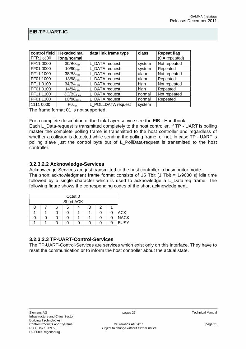
control field FFR1 cc00
Hexadecimal long/normal
data link frame type class Repeat flag (0 = repeated)
FF11 0000 30/B0Hex L_DATA request system Not repeated FF01 0000 10/90Hex L_DATA request system Repeated FF11 1000 38/B8Hex L_DATA request alarm Not repeated FF01 1000 18/98Hex L_DATA request alarm Repeated FF11 0100 34/B4Hex L_DATA request high Not repeated FF01 0100 14/94Hex L_DATA request high Repeated FF11 1100 3C/BCHex L_DATA request normal Not repeated FF01 1100 1C/9CHex L_DATA request normal Repeated 1111 0000 F0Hex L_POLLDATA request system
The frame format 01 is not supported. For a complete description of the Link-Layer service see the EIB - Handbook. Each L_Data-request is transmitted completely to the host controller. If TP - UART is polling master the complete polling frame is transmitted to the host controller and regardless of whether a collision is detected while sending the polling frame, or not. In case TP - UART is polling slave just the control byte out of L_PollData-request is transmitted to the host controller. 3.2.3.2.2 Acknowledge-Services Acknowledge-Services are just transmitted to the host controller in busmonitor mode. The short acknowledgment frame format consists of 15 Tbit (1 Tbit = 1/9600 s) idle time followed by a single character which is used to acknowledge a L_Data.req frame. The following figure shows the corresponding codes of the short acknowledgment.
Octet 0 Short ACK
8 7 6 5 4 3 2 1 1 1 0 0 1 1 0 0 ACK 0 0 0 0 1 1 0 0 NACK 1 1 0 0 0 0 0 0 BUSY
3.2.3.2.3 TP-UART-Control-Services The TP-UART-Control-Services are services which exist only on this interface. They have to reset the communication or to inform the host controller about the actual state.
GAMMA instabus Release: December 2011
EIB-TP-UART-IC
Technical Manual pages 27 Siemens AG Infrastructure and Cities Sector,
Building Technologies page 22 © Siemens AG 2011 Control Products and Systems Subject to change without further notice. P. O. Box 10 09 53, D-93009 Regensburg
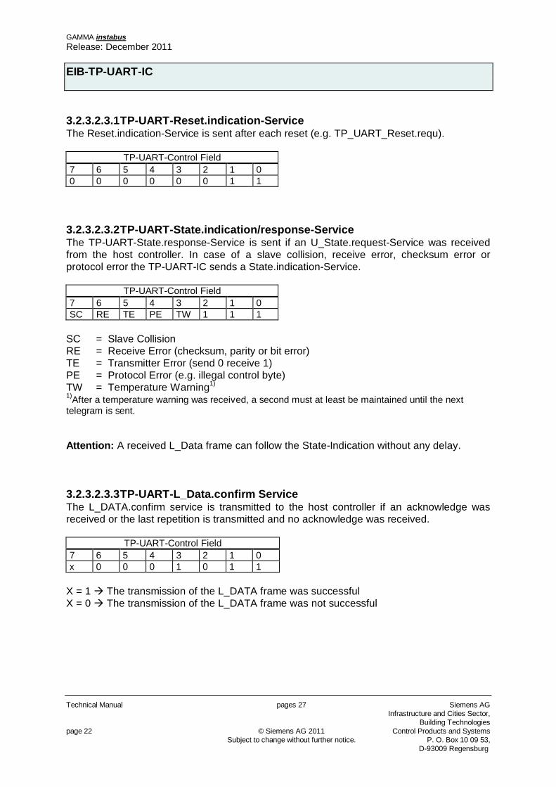
3.2.3.2.3.1 TP-UART-Reset.indication-Service The Reset.indication-Service is sent after each reset (e.g. TP_UART_Reset.requ).
TP-UART-Control Field 7 6 5 4 3 2 1 0 0 0 0 0 0 0 1 1
3.2.3.2.3.2 TP-UART-State.indication/response-Service The TP-UART-State.response-Service is sent if an U_State.request-Service was received from the host controller. In case of a slave collision, receive error, checksum error or protocol error the TP-UART-IC sends a State.indication-Service.
TP-UART-Control Field 7 6 5 4 3 2 1 0 SC RE TE PE TW 1 1 1
SC = Slave Collision RE = Receive Error (checksum, parity or bit error) TE = Transmitter Error (send 0 receive 1) PE = Protocol Error (e.g. illegal control byte) TW = Temperature Warning1)
1)After a temperature warning was received, a second must at least be maintained until the next telegram is sent. Attention: A received L_Data frame can follow the State-Indication without any delay.
3.2.3.2.3.3 TP-UART-L_Data.confirm Service The L_DATA.confirm service is transmitted to the host controller if an acknowledge was received or the last repetition is transmitted and no acknowledge was received.
TP-UART-Control Field 7 6 5 4 3 2 1 0 x 0 0 0 1 0 1 1
X = 1 The transmission of the L_DATA frame was successful X = 0 The transmission of the L_DATA frame was not successful
GAMMA instabus Release: December 2011
EIB-TP-UART-IC
Siemens AG pages 27 Technical Manual Infrastructure and Cities Sector, Building Technologies Control Products and Systems © Siemens AG 2011 page 23 P. O. Box 10 09 53, Subject to change without further notice. D-93009 Regensburg
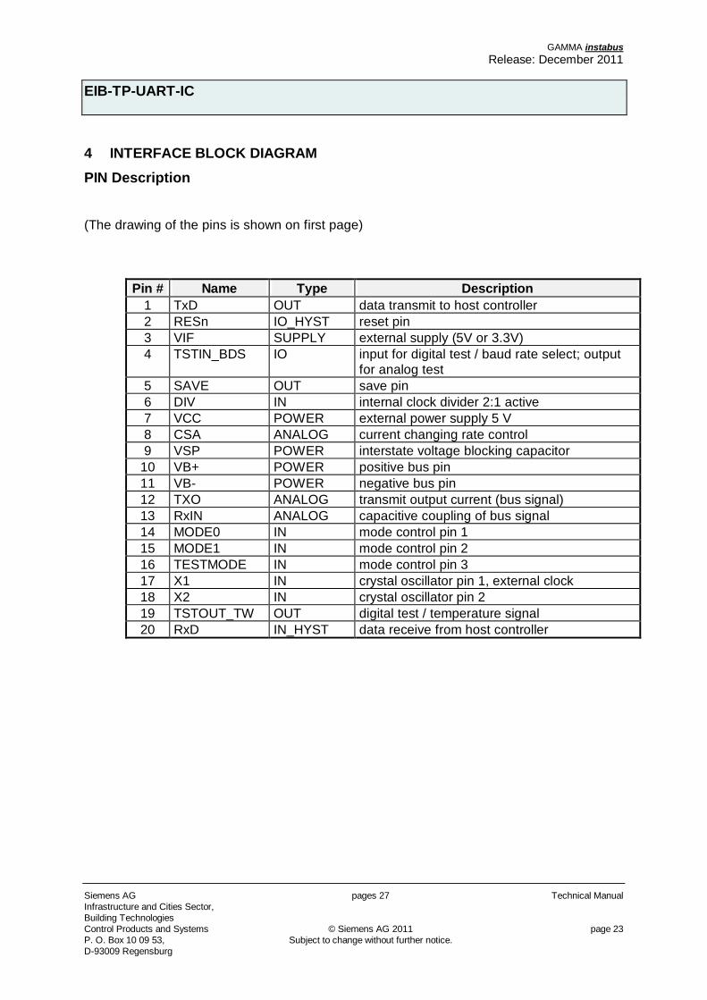
4 INTERFACE BLOCK DIAGRAM PIN Description (The drawing of the pins is shown on first page)
Pin # Name Type Description 1 TxD OUT data transmit to host controller 2 RESn IO_HYST reset pin 3 VIF SUPPLY external supply (5V or 3.3V) 4 TSTIN_BDS IO input for digital test / baud rate select; output
for analog test 5 SAVE OUT save pin 6 DIV IN internal clock divider 2:1 active 7 VCC POWER external power supply 5 V 8 CSA ANALOG current changing rate control 9 VSP POWER interstate voltage blocking capacitor
10 VB+ POWER positive bus pin 11 VB- POWER negative bus pin 12 TXO ANALOG transmit output current (bus signal) 13 RxIN ANALOG capacitive coupling of bus signal 14 MODE0 IN mode control pin 1 15 MODE1 IN mode control pin 2 16 TESTMODE IN mode control pin 3 17 X1 IN crystal oscillator pin 1, external clock 18 X2 IN crystal oscillator pin 2 19 TSTOUT_TW OUT digital test / temperature signal 20 RxD IN_HYST data receive from host controller

GAMMA instabus Release: December 2011
EIB-TP-UART-IC
Technical Manual pages 27 Siemens AG Infrastructure and Cities Sector,
Building Technologies page 24 © Siemens AG 2011 Control Products and Systems Subject to change without further notice. P. O. Box 10 09 53, D-93009 Regensburg
5 MECHANICAL SPECIFICATION
SOIC 20 (300 MIL) Dimensions (mm)
min. nom. Max. A 2.46 2.56 2.64 A1 0.127 0.22 0.29 A2 2.29 2.34 2.39 B 0.35 0.41 0.48 C 0.23 0.25 0.32 D 12.70 12.83 12.95 E 7.42 7.52 7.59 e 1.27 BSC H 10.16 10.31 10.41 h 0.25 0.33 0.41 L 0.61 0.81 1.02
0o 5o 8o
B
D
e
HE
h x 45o
C L
1
A1
A2A
GAMMA instabus Release: December 2011
EIB-TP-UART-IC
Siemens AG pages 27 Technical Manual Infrastructure and Cities Sector, Building Technologies Control Products and Systems © Siemens AG 2011 page 25 P. O. Box 10 09 53, Subject to change without further notice. D-93009 Regensburg
6 APPENDIX 6.1 Typical Application Circuits 6.1.1 Normal Mode
U2
SMAJ43CA
RESn
TxD
C510n
GND
+
C4100u/16V
B
SAVE
D1
BYG21MA
+
C36,8u
RxD
C2
47n/50V
C1
47n/50V
U1
TP-UART-01
2
3
4
5
6
7
8
9
10
20
19
18
17
16
15
14
13
12
11
1
RESn
VIF
TSTIN
SAVE
DIV
VCC
CSA
VSP
VB+
RxD
TSTOUT
X2
X1
TEST MODE
MODE1
MODE0
RxIN
TxO
VB-
TxD
R1
68/1W
2)
TSTIN = Low => 19200 Baud
Y1
4,915MHz
VCC
2)
VCC
C610n
3)
2) recommended (close to Pins VSP and VCC)
3) Buffertime of VCC after SAVE active, see 1.2.13
GAMMA instabus Release: December 2011
EIB-TP-UART-IC
Technical Manual pages 27 Siemens AG Infrastructure and Cities Sector,
Building Technologies page 26 © Siemens AG 2011 Control Products and Systems Subject to change without further notice. P. O. Box 10 09 53, D-93009 Regensburg
6.1.2 Analogmode
+
C36,8u
+
C4100u/16V
VCC
RESn
SAVE
B
U2
SMAJ43CA
2)
GND
TxD
RxD
D1
BYG21MA
VCC
C610n
2)
C1
47n/50V
C2
47n/50V
R1
68/1W
U1
TP-UART-01
2
3
4
5
6
7
8
9
10
20
19
18
17
16
15
14
13
12
11
1
RESn
VIF
TSTIN
SAVE
DIV
VCC
CSA
VSP
VB+
RxD
TSTOUT
X2
X1
TEST MODE
MODE1
MODE0
RxIN
TxO
VB-
TxD
C510n
3)
1)
1) The maximum average powerdissipation of the transmitting resistance of 1 W is valid for an active telegramrate of 50 %
2) recommended (close to Pins VSP and VCC)
3) Buffertime of VCC after SAVE active, see 1.2.13
GAMMA instabus Release: December 2011
EIB-TP-UART-IC
Siemens AG pages 27 Technical Manual Infrastructure and Cities Sector, Building Technologies Control Products and Systems © Siemens AG 2011 page 27 P. O. Box 10 09 53, Subject to change without further notice. D-93009 Regensburg
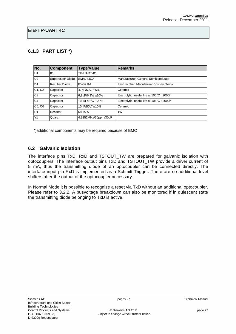
6.1.3 PART LIST *)
No. Component Type/Value Remarks U1 IC TP-UART-IC
U2 Suppressor Diode SMAJ43CA Manufacturer: General Semiconductor
D1 Rectifier Diode BYG21M Fast rectifier, Manufaturer: Vishay, Temic
C1, C2 Capacitor 47nF/50V/ 5% Ceramic
C3 Capacitor 6,8uF/6.3V/ 20% Electrolytic, useful life at 105°C : 2000h
C4 Capacitor 100uF/16V/ 20% Electrolytic, useful life at 105°C : 2000h
C5, C6 Capacitor 10nF/50V/ 10% Ceramic
R1 Resistor 68/ 5% 1W
Y1 Quarz 4.9152MHz/50ppm/30pF
*)additional components may be required because of EMC
6.2 Galvanic Isolation The interface pins TxD, RxD and TSTOUT_TW are prepared for galvanic isolation with optocouplers. The interface output pins TxD and TSTOUT_TW provide a driver current of 5 mA, thus the transmitting diode of an optocoupler can be connected directly. The interface input pin RxD is implemented as a Schmitt Trigger. There are no additional level shifters after the output of the optocoupler necessary. In Normal Mode it is possible to recognize a reset via TxD without an additional optocoupler. Please refer to 3.2.2. A busvoltage breakdown can also be monitored if in quiescent state the transmitting diode belonging to TxD is active.