Chimney fans, controllers and accessories in systems for ...
16
Technical data Chimney fans, controllers and accessories in systems for gas fireplaces, stoves and single non-modulating gas boilers
Transcript of Chimney fans, controllers and accessories in systems for ...

Technical data Chimney fans, controllers and accessories in systems for gas fireplaces, stoves and single non-modulating gas boilers

Systems for gas fireplaces and gas stoves
In addition, the exodraft chimney fan system gives you the freedom to choose your gas fireplace on the basis of what you want, rather than what the building architec-ture or layout will allow. In some countries the system can be used together with a wall-mounted chimney fan.
An exodraft chimney fan system for a gas fireplace or stove consists of a chimney fan with a flow measuring system, a GASTEC approved fan controller and accesso-ries.
Four types of exodraft chimney fans are available for gas: RHG & RSHG with horizontal discharge, RSVG with vertical discharge and the wall mounted RSG. They are all fitted with a flow measurement system which – together with type EFC21 or EFC25 control systems – ensure that gas is not supplied to the fireplace unless there is suf-ficient draught in the chimney.
When switched on, a signal is sent to the chimney fan to create the optimal updraft in the chimney. Only when this is reached will the control system allow gas into the fireplace enabling the fire to be lit. Any reduction in up-draft will result in the gas supply to the fire being cut and the fire being switched off.
This is the only system on the market that have the sought after EN298 GASTEC approval.
The design of the optimum system components for the individual system is calculated using design software de-veloped by exodraft in accordance with BS EN 13384
All exodraft system designs come with two years warran-ty, extendable to three years warranty when utilising the exodraft trained engineers (see our website for details).
The exodraft chimney fan systems for open gas fireplaces are the only ones on the market that feature an approved fail-safe function. This ensures that your family is not exposed to any unnecessary hazards from your open gas fire. Our systems can be used either on existing fireplaces or new installations.
1
4
2
5
3
1
4
2
3
Components Type Page
Chimney fans RHG 4
RSHG 6
RSVG 8
RSG 10
Controls EFC21 12
EFC25 13
Isolation switch REPSW2x16 14
Accessoriesfor installation
Flange 14
Solenoid valve SMG 12SMG 14
14
1
4
5
2
3
Find the components you need here:
5
2

Components for single non-modulating gas boilers
Components Type Page
Chimney fans RHG 4
RSHG 6
RSVG 8
RSG 10
Controls EFC21 12
EFC25 13
Isolation switch REPSW2x16 14
Accessoriesfor installation
Flange 14
1
4
2
3
Find the components you need here:
An exodraft chimney fan system for a single non- modulating gas boilersconsists of a chimney fan with a flow measuring system, a GASTEC approved fan control and accessories. It is used where there is a need for design flexibility, enhanced energy performance of the appliances or guarantee against spillage of combustion materials or Carbon monoxide.
When switched on, a signal is sent to the chimney fan to create the optimal updraft in the chimney. Only when this is reached will the control system allow gas into the boiler enabling the burner to be lit. Any reduction in updraft will result in the gas supply to the fire being cut and the fire being switched off.
Four types of exodraft chimney fans are available for gas: RHG & RSHG with horizontal discharge, RSVG with vertical discharge and the wall mounted RSG. They are all fitted with a flow measurement system which – together with type EFC21 or EFC25 control systems – ensure that gas is not supplied to the boiler unless there is sufficient draught in the chimney.
This is the only system on the market that have the sought after EN298 GASTEC approval.
The design of the optimum system components for the individual system is calculated using design software de-veloped by exodraft in accordance with BS EN 13384
All exodraft System Designs come with two years warran-ty, extendable to three years warranty when utilising the exodraft trained engineers (see our website for details).
4
34
12
3
The exodraft chimney fan system for single non-modulating gas boiler installations offers great possibili-ties within flue and chimney design. The stepless adjustable fan motor and the electronic control ensure a constant draft that guarantees combustion and better heating economy. Large savings on flue systems and installation costs are available as downsizing of flue diameters and chimney heights becomes possible.
KTR 20 RS
1
2
3
A
B
1
2
3 4
DescriptionAn exodraft chimney fan RHG160 is suitable for gas stoves and small gas fireplaces. The fan has a built-in fail-safe system consisting of a pressure differential switch and a flow measuring system. The fail-safe system com plies with BS5440: 2000 Part 1 and BS6644: 1991.
The fan is mounted on top of the chimney and pro-vides a controllable negative pressure in the flue and chimney. The fan has a horizontal discharge and can withstand temperatures up to 200 °C at the flue exit or chimney top.
The RHG160 fan guarantees optimum draught irrespec-tive of the placement, dimensions or height of the chim-ney which is beneficial to new or existing installations.
The fan must be connected to an exodraft control type EFC21 or EFC25 for the failsafe system to work.
ConstructionThe exodraft chimney fan RHG160 is constructed of corrosion resistant cast aluminium and are designed to work reliably in a hot and corrosive environment year after year.
The fan has horizontal discharge and can withstand temperatures up to 200 °C at the flue exit or chimney top.
The fan is fitted with an entirely closed, asynchronous motor with ball bearings sealed for life. The motor is specifically constructed to provide reliable operation at a high temperature. It is made to international classifica-tions IP54 (protection class) and F (insulation).
The motor is located inside the motor housing and thus separated from the flue gases. The electrical connection is provided by a heat resistant silicone cable withstand-ing 200 °C. The RHG160 is fitted with a centrifugal impel-ler.
The fan is easily removable for service and maintenance.The built-in pressure switch in the chimney fan is wired to the appro priate exodraft control unit which super-vises the fail-safe function. Only when the draught exceeds the preset and safe level can the gas appliance be used.
The fail-safe system will prevent any spillage of com-bustion products from the appliance when the fan and controller are commissioned correctly. In case of insuf-ficient chim ney draught, the heating appliance will be shut down.
Chimney fan RHG160
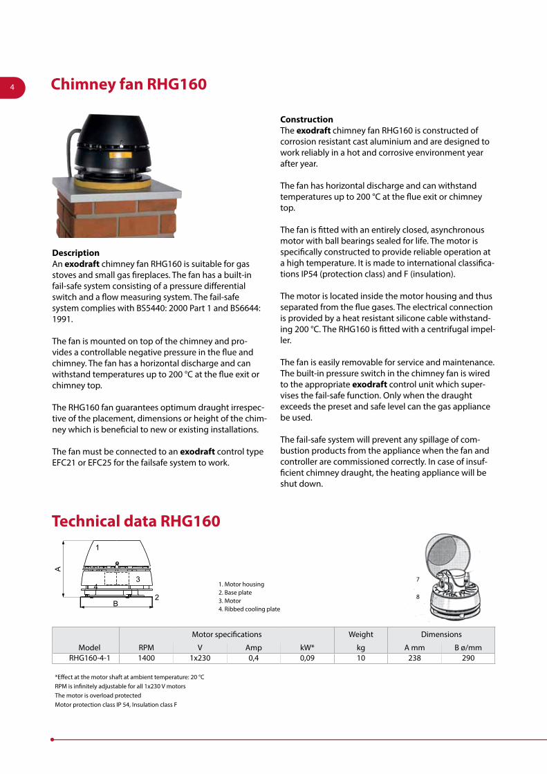
Technical data RHG160
Motor specifications Weight Dimensions
Model RPM V Amp kW* kg A mm B ø/mmRHG160-4-1 1400 1x230 0,4 0,09 10 238 290
*Effect at the motor shaft at ambient temperature: 20 °CRPM is infinitely adjustable for all 1x230 V motorsThe motor is overload protectedMotor protection class IP 54, Insulation class F
1. Motor housing2. Base plate3. Motor4. Ribbed cooling plate
7
8
4

0 100
30 60 90
200 300 m3/h
l/s
50
100
150
200
Ps [Pa]
RHG160
Chimney fan selection RHG160
Please use the exodraft fan selection chart or complete an appraisal form. exodraft offers a free fan selection service - the correct chimney fan and control unit are calculated according to BS EN 13384
The capacity chart is measured at a flue gas temperature of 20 °C. The fan capacity changes with temperature.
Correction of system pressure loss for flue gas temperature higher than 20 °C is calculated: Ps20 = Pst x 273 + t (°C) 293 t = temperature measured in °C
ExampleSystem need: 200 m3/h and 25 Pa at 180 °CSelection of fan: 200 m3/h and 39 Pa at 20 °C
Type FlueRHG160 ø 160 mm
at 1400 RPM
5

DescriptionAn exodraft chimney fan RSHG is specially designed to work with heating appliances burning gas. The fans have a built-in fail-safe system consisting of a pressure differential switch and a flow measuring system. The fail-safe system com plies with BS5440: 2000 Part 1 and BS6644: 1991.
The fan is mounted on top of the chimney and pro-vides a controllable negative pressure in the flue and chimney. The fan has a horizontal discharge and can withstand temperatures up to 200 °C at the flue exit or chimney top.
The RSHG fans guarantee optimum draught irrespective of the placement, dimensions or height of the chimney which is beneficial to new or existing installations.The fan must be connected to an exodraft control type EFC21 or EFC25.
ConstructionThe exodraft chimney fans RSHG are constructed of corrosion resistant cast aluminium and are designed to work reliably in a hot and corrosive environment year after year.
The fan has horizontal discharge and can withstand temperatures up to 200 °C at the flue exit or chimney top.
RSHG is supplied with an axial vane of stainless steel and a mesh safety guard covering the horizontal discharge. All fans are hinged, providing easy access for service and maintenance.
The fan is fitted with an entirely closed, asynchronous motor with ball bearings sealed for life. The motor is specifically constructed to provide reliable operation at a high temperature. It is made to international classi-fications IP54 (protection class) and F (insulation). The motor is located inside the motor housing and thus seperated from the flue gases. The electrical connection is provided by a heat resistant silicone cable withstand-ing 200 °C
The built-in pressure switch in the chimney fan is wired to the appro priate exodraft control unit which super-vises the fail-safe function. Only when the draught exceeds the preset and safe level can the gas appliance be used. The fail-safe system will prevent any spillage of combustion products from the appliance when the fan and controller are commissioned correctly. In case of insufficient chim ney draught, the heating appliance will be shut down.
Chimney fan RSHG
Technical data RSHG
B
2
5
7
4 8
3 1
C
DA
6E
1. Motor cable2. Motor housing3. Motor4. Vane5. Ribbed cooling plate
6. Base plate7. Hinges8. Locking nut9. Pressure Differential Switch10. Flowmeasurer
9
10
*Effect at the motor shaft at ambient temperature: 20°CRPM is infinitely adjustable for all 1x230 V motors. • The motor is overload protected • Motor protection class IP 54, Insulation class F
Motor specifications Weight Dimensions
Model RPM V Amp kW* kg A mm BxB mm C ø/mm D mm E ø/mmRSHG012-4-1 1400 1x230 0,4 0,03 14 275 365 350 85 165RSHG014-4-1 1400 1x230 0,4 0,04 18 330 420 395 100 188
6

Chimney fan selection RSHG
The capacity chart is measured at a flue gas temperature of 20 °C. The fan capacity changes with temperature.Correction of system pressure loss for flue gas temperature higher than 20 °C is calculated:
Ps20 = Pst x 273 + t (°C) 293 t = temperature measured in °C
ExampleSystem need: 500 m3/h and 90 Pa at 180 °CSelection of fan: 500 m3/h and 139 Pa at 20 °C
Please use the exodraft fan selection chart or complete an appraisal form. exodraft offers a free fan selection service – the correct chimney fan and control unit are calculated according to BS EN 13384
Type Flue
RSHG12 ø 200 mm
RSHG14 ø 250 mm
at 1400 RPM.
0 100 200 300 400 500 600 700 800 900 1000
10
20
30
40
50
6070
80
84,2 111 13927,80 55,6 222 250 278166,7 195
m3/h
l/s
RSHG014RSHG012
Ps [Pa]
Sound levels
Sound levels to external surroundings. Measured in accordance to ISO 3744
Sound levels to flue pipe. Measured in accordance to ISO 5136
ModelLw (dB) Lp
dB (A)125 Hz 250 Hz 500 Hz 1000 Hz 2000 Hz 4000 Hz 8000 HzRSHG012-4-1 64 60 55 52 48 42 34 30RSHG014-4-1 75 69 65 62 57 51 44 41
ModelLw (dB) Lw
dB(A)Lp
dB (A)125 Hz 250 Hz 500 Hz 1000 Hz 2000 Hz 4000 Hz 8000 HzRSHG012-4-1 72 65 59 49 47 41 31 61 53RSHG014-4-1 82 73 63 58 52 48 38 68 61
Tolerance +/-3 dBLw = Sound effect level dB. (reference: 1 pW)Lp = Sound Pressure level dB (A) at a distance of 10 m from the fan at half-spheric sound distribution.Lp = (5 metres) = Lp (10 metres) + 6dB Lp = (20 metres) = Lp (10 metres) - 6dB
7

Motorspecification Weight Dimensions (in mm)Model RPM V Amp kW* kg A B x B C x C D Ø E
RSVG200-4-1 1400 1x230 0,4 0,07 18 280 390 310 200 80RSVG250-4-1 1400 1x230 0,8 0,16 27 335 485 385 250 100RSVG315-4-1 1400 1x230 1,8 0,37 37 380 580 465 315 115
*Effect at the motor shaft at ambient temperature: 20 °CRPM is infinitely adjustable for all 1x230 V motorsThe motor is overload protectedMotor protection class IP 54, Insulation class F
Technical data RSVG
AE
DCB
12 3
4
5
6
7
8
1. Motor cable2. Motor housing3. Motor4. Centrifugal impeller5. Bottom section6. Locking nuts7. Handle8. Hinges
DescriptionAn exodraft chimney fan RSVG is specially designed to work with heating appliances burning gas. The fans have a built-in fail-safe system consisting of a pressure differential switch and a flow measuring system. The fail-safe system com plies with BS5440: 2000 Part 1 and BS6644: 1991.
The fans are normally installed on top of the chimney where the ver tical discharge column prevents a plume of gas flowing down outside of the chim ney. The RSVG can also be wall mounted.
exodraft chimney fans RSVG are used with gas heating appliances and provide a controllable negative pressure along the full length of the flue and chimney. The fans guarantee optimum chimney draught irre spec tive of the pla cement, dimen sions or height of the chim ney which is beneficial to new or existing instal lations.
The fan must be connected to an exodraft control type EFC21 or EFC25.
ConstructionThe exodraft chimney fans RSVG are constructed of corrosion resistant cast aluminium and are designed to work reliably in a hot and corrosive environment year after year.
The fan has vertical discharge and is specially made to withstand continuous flue gas temperatures up to 200 °C.
RSVG fans are supplied with a backward curved impel-ler, which gives excellent fan efficiency. A mesh safety guard of stainless steel covers the vertical discharge. All fans are hinged, providing easy access for service and maintenance.
The fans are fitted with an entirely closed, asynchronous motor with ball bearings sealed for life. The motor is specifically constructed to provide reliable operation at a high temperature. It is made to international classi-fications IP54 (protection class) and F (insulation). The motor is located inside the motor housing and thus seperated from the flue gases. The electrical connection is provided by a heat resistant silicone cable withstand-ing 200 °C
The built-in pressure switch in the chimney fan is wired to the appro priate exodraft control unit which super-vises the fail-safe function. Only when the draught exceeds the preset and safe level can the gas appliance be used. The fail-safe system will prevent any spillage of combustion products from the appliance when the fan and controller are commissioned correctly. In case of insufficient chim ney draught, the heating appliance will be shut down.
Chimney fan RSVG
PDS(PressureDi�erentialSwitch)
Flow system
8

ModelLw (dB) Lp
dB (A)125 Hz 250 Hz 500 Hz 1000 Hz 2000 Hz 4000 Hz 8000 Hz
RSVG200-4-1 58 60 62 61 56 44 37 36RSVG250-4-1 64 68 66 65 61 49 45 41RSVG315-4-1 71 75 70 73 68 57 52 48
Chimney fan selection RSVG
Sound levels RSVGSound levels to external surroundings. Measured in accordance to ISO 3744
Please use the exodraft fan selection chart or complete an appraisal form. exodraft offers a free fan selection service - the correct chimney fan and control unit are calculated according to EN 13384
Type Flue
RSVG200 ø 200 mm
RSVG250 ø 250 mm
RSVG315 ø 315 mm
at 1400 RPM
Sound levels to flue pipe. Measured in accordance to ISO 5136
Model Lw (dB) Lw dB (A)
Lp dB (A)125 Hz 250 Hz 500 Hz 1000 Hz 2000 Hz 4000 Hz 8000 Hz
RSVG200-4 65 62 62 58 48 41 30 63 55RSVG250-4 72 69 65 63 56 48 41 68 61RSVG315-4 74 73 70 71 63 53 47 74 69
Tolerance +/-3 dBLw = Sound effect level dB. (reference: 1 pW)Lp = Sound Pressure level dB (A) at a distance of 10 m from the fan at half-spheric sound distribution.Lp = (5 metres) = Lp (10 metres) + 6dB Lp = (20 metres) = Lp (10 metres) - 6dB
The capacity chart is measured at a flue gas temperature of 20 °C. The fan capacity changes with temperature.Correction of system pressure loss for flue gas temperature higher than 20 °C is calculated: Ps20 = Pst x 273 + t (°C) 293 t = temperature measured in °C
ExampleSystem need: 500 m3/h and 90 Pa at 180 °CSelection of fan: 500 m3/h and 139 Pa at 20 °C
0
0
500
800
1000 1500 2000 2500 3000 m3/h
l/s
0
50
100
150
200
250
300
350
400
Ps [Pa]
RSVG200
RSVG250
RSVG315
100 200 300 400 500 600 700
9

DescriptionAn exodraft chimney fan RSG provide a controllable negative pressure along the full length of the flue and chimney.
A fail-safe system is fitted in the fan which automatically measures the velocity of the flue gases. Only when the velocity exceeds the preset and safe level can the gas appliance be used. The fail-safe system prevents any spillage from the gas appliance as well as any leaks of CO and other poisonous gases.
Fan type RSG is installed on the external wall and there-by enables a gas appliance to be installed in a room with no chimney. The power of the fan will allow for long horizontal flues up to 15 meters.
A silencer type SLR is available as an accessory for the fan type RSG.
ConstructionThe fans are specially made to work in a hot and dirty environment and can withstand temperatures up to 180 °C at the flue exit.
The fans are made from galvanised sheet metal, fitted with a centrifugal impeller that is very resistant to dirt in the flue gases.
The fans are fitted with an entirely closed, asynch ronous motor with ball bearings sealed for life. The motor is specifically constructed to provide reliable operation at a high temperature. It is made to international classi-fications IP54 (protection class) and F (insulation). The motor is located inside the motor housing and thus separated from the flue gases.
The electrical connection is provided by a heat resistant silicone cable withstanding 200 °C.
The built-in pressure switch in the chimney fan is wired to the appro priate exodraft control unit which super-vises the fail-safe function. Only when the draught exceeds the preset and safe level can the gas appliance be used. The fail-safe system will prevent any spillage of combustion products from the appliance when the fan and the controller are commissioned correctly. In case of insufficient chim ney draught, the heating appliance will be shut down.
Chimney fan RSG
G C
F B E
H
K
D
J
A
L
FAN
A
B C D
G C
F EB
D
J
A
L
K
H
Type A BINSIDE
CINSIDE D
SLR125-280 280 ø125 ø128 ø240SLR150-280 280 ø150 ø153 ø265SLR200-280 280 ø203 ø206 ø318SLR200-600 600 ø203 ø206 ø318
Technical data RSG
Install Accessory: Silencer SLR
Motorspecification Weight Dimensions in mm
Model RPM V Amp kW* kg A B C D E Foutside G H J K L
RSG125-4-1 1400 1x230 0,3 0,04 11 265 250 220 336 320 ø121 35 280 296 153 157RSG150-4-1 1400 1x230 0,2 0,05 14 325 310 240 400 380 ø146 35 340 360 181 186RSG200-4-1 1400 1x230 0.4 0,11 20 405 380 275 478 453 ø196 35 413 438 215 221
*Effect at the motor shaft at ambient temperature: 20 °CRPM is infinitely adjustable for all 1x230 V motorsThe motor is overload protectedMotor protection class IP 54, Insulation class F
10

Soundpower levels to flue pipe. Measured in accordance to ISO 5136
ModelLw (dB) Lp
dB (A)125 Hz 250 Hz 500 Hz 1000 Hz 2000 Hz 4000 Hz 8000 HzRSG125 60 59 56 50 49 42 34 49RSG150 61 66 61 56 53 47 40 55RSG200 69 72 68 62 59 55 49 61
Soundpower levels to external surroundings. Measured in accordance to ISO 3744
ModelLw (dB) Lw
dB (A)Lp
dB (A)125 Hz 250 Hz 500 Hz 1000 Hz 2000 Hz 4000 Hz 8000 HzRSG125-4-1 66 59 48 44 40 30 21 54 29RSG150-4-1 75 67 52 50 44 36 29 61 35RSG200-4-1 80 69 59 56 51 45 36 66 41
Sound absorbed using silencer SLR (Lw to flue pipe)
ModelLw (dB)
125 Hz 250 Hz 500 Hz 1000 Hz 2000 Hz 4000 Hz 8000 HzSLR125-280 4 6 11 21 18 12 12SLR150-280 2 4 11 19 14 14 9SLR200-280 1 2 10 16 12 12 7
Tolerance +/-3 dbLw = Sound effect level dB. (reference: 1 pW)Lp = Sound Pressure level dB (A) at a distance of 10 m from the fan at halfspheric sound distribution. Lp (2 metres) = Lp (1 metre) - 6 dB.
Chimney fan selection RSGPlease use the exodraft fan selection chart or complete an appraisal form. exodraft offers a free fan selection service – the correct chimney fan and control unit are calculated according to EN 13384
240
200
160
120
80
40
0
0 100 200 300 400 500 600 m³/h
90 110 14030 l/s0 60 170
RSG125
RSG 150
RSG 200
Ps [Pa]
The capacity chart is measured at a flue gas temperature of 20 °C. The fan capacity changes with temperature.Correction of system pressure loss for flue gas temperature higher than 20 °C is calculated: Ps20 = Pst x 273 + t (°C) 293 t = temperature measured in °C
ExampleSystem need: 500 m3/h and 90 Pa at 180 °CSelection of fan: 500 m3/h and 139 Pa at 20 °C
Sound levels RSG 11

Descriptionexodraft controller EFC21 has been developed for use with gas fireplaces where an exodraft chimney fan or wall fan is installed.
The control system supervises the fail-safe function. In case of insufficient chimney draught, the EFC21 will shut off the gas supply.
The control system is developed to meet BS 5440: Part 1 (2000), BS 6644 (1991), Gas Appliance Directive 90/396/EEC, EN298 (2003) and other relevant European standards.
The system consists of: 1. Chimney fan2. Controller EFC213. Solenoid valve SMG (or-der seperately - see details below)
FunctionBy activating EFC21 the chimney fan will immedi-ately start up on full speed. When the fail-safe supervi-sion confirms sufficient chimney draught, the fireplace can be lit and the fan speed will adjust to the pre-set value set during commissioning.
The controller has a step-up function and a 15-second built-in delay function to avoid nuisance cut-outs. When EFC21 is turned off, the chimney fan stops. It is possible to pre-set a post-purge period of 3 minutes.
The step-up function is part of the fail-safe system. Should the draught fail during normal operating conditions: the controller will increase the fan speed to compensate. This usually occurs on days that are windier than the commissioning day. If sufficient draught cannot be re-established, the EFC21 will shut off the gas supply.
Solenoid valve SMGSMG12: Solenoid valve for EFC21 for 1/2” pipeSMG14: Solenoid valve for EFC21 for 1/4” pipe.
EFC21 control
Description Data EFC21
Height (mm) 85
Width (mm) 126
Depth (mm) 32
Fuse rating (amps) (A) 3.15 A T
Fail safe (B) Pressure differential switch (PDS)
24 V DC (Closed circuit supply)
Output to chimney fan (C) 1.8 A/230 V (AC 3)
Output to soleniod valve (SMG) (D)
230 V AC max. 100 V A
Dipswitch options (E)• Manual reset• Post-purge 3 min. period
Set-point running speed (F) Potentiometer on PCB
Supply (G) 230 V +/- 10 %, 50 Hz
Input for external on/off switch (H)
24 V DC (Closed circuit supply)
Release out Relay (I) Max. 3 A 230 V AC / 3A 30 V DC (Fused: 3.15AT)
Operating temperature -10 °C to 40 °C
Degree of protection IP 30
Material ABS
Colour White
CE-Approval No. 0063BN1144 based on EN298 (2003)
Usable with the following chim-ney fans in this brochure
RHG, RSHG, RSVG, RSG
EFC21
EFC21 technical data1
2
3
12

Description Data EFC25
Height (mm) 85
Width (mm) 126
Depth (mm) 32
Fuse rating (amps) (A) 3.15 A T
Fail safe (B) Pressure differential switch (PDS)
24 V DC (Closed circuit supply)
Output to chimney fan (C) 1.8 A/230 V (AC 3)
Dipswitch options (E)• Manual reset• 3 min. post-purge period
Set-point running speed (F) Potentiometer on PCB
Supply (G) 230 V +/- 10 %, 50 Hz
Input for external on/off switch (H)
24 V DC (Closed circuit supply)
Release out Relay (I)Max. 3 A 230 V AC / 3A 30 V DC (Fused: 3.15 AT)
Release step 2 Relay (J) Max. 5A 230 V AC/5A 30 V DC
Operating temperature -10 °C to 40 °C
Degree of protection IP 30
Material ABS
Colour White
Socket for external IR-sensor (F)Option: IR-sensor with 10 meter cable [p/n 0501014]
CE-Approval No.0063BN1144 based on EN298 (2003)
Usable with the following chim-ney fans in this brochure
RSH, RSHG, RSVG, RSG
EFC25 controlDescriptionexodraft controller EFC25 with remote control has been developed for use with exodraft chimney fans or wall fans but only in connection with gas fireplaces with flame detection devices and automatic ignition. The control system supervises the fail-safe function and integrates with the fireplace control by means of two relays. There is no solenoid output from EFC25.
The control system supervises the fail-safe function. In case of insufficient chimney draught, the EFC25 will shut down the fireplace.
The control system is developed to meet BS 5440: Part 1 (2000), BS 6644 (2005), Gas Applicance Directive 90/396/EEC, EN298 ((2003)) and other relevant Euro-pean standards.
The system consists of: 1. Chimney fan2. Controller EFC253. Remote sensing eye (optional)
FunctionBy activating the remote control the chimney fan will immediately start up on full speed. When the fail-safe supervision confirms sufficient chimney draught, the fireplace will be lit and the fan speed will adjust to the preset value set during commissioning.
The remote control can also be used to switch be-tween high and low flame where applicable and to adjust the fan speed, when the fan is used for ventila-tion purposes.
The controller has a step-up function and a 15-second built-in delay function to avoid nuisance cut-outs. When EFC25 is turned off, the chimney fan stops.
It is possible to preset a post-purge period of 3 minutes. The step-up function is part of the fail-safe system. Should the draught fail during normal oper-ating conditions: the controller will increase the fan speed to compensate. This usually occurs on days that are windier than the commission ing day. If sufficient draught cannot be re-established, the EFC25 will shut down the fireplace.
EFC25 technical data
EFC25
Remote control
13

Type mm Chimney diameter Chimney fan
FR2 310 x 310 125 - 150 - 175 - 200 - 250 RSVG200,
FR3 395 x 395 150 - 175 - 200 - 250 - 300- 350 RSVG250, RSHG12, RSHG14,
FR4 500 x 500 200 - 250 -300 - 350 - 400 - 450 RSVG315,
FR2-02 310 x 310 150-160-200 RHG160
Spigot length 120 mm
FR
REPSW2x16
FR-02
Type Description Used with controls
REPSW2x16 4-pole* isolation switch EFC21, EFC25
* 3-pole with help switch
Type Description
SMG12 Solenoid valve for 1/2” pipe
SMG14 Solenoid valve for 1/4” pipe
FR flanges from exodraft are used to install exodraft chimney fans on steel chimneys.
The flanges are made of stainless steel and ensure that the chimney fans have a flat and level installation base. The flange is supplied with four vibra-tion dampers that reduce vibrations and help create a stable base for the chimney fan.
The diameter of the flange spigot is 3 mm smaller than the diameter of the chimney. For example, the diameter of the spigot of an FR1-200 is Ø 197 mm, designed to fit into a chimney opening with a Ø 200 mm diameter.
The flange range caters for all types of chimney fans and chimneys. Flanges with diameters other than those shown in the table can be made to order.
FR flange
Isolation switch
Solenoid valve
It is a legal requirement that an isolation switch is installed in the immediate vicinity of the chimney fan, so that, for example, chimney sweeps can discon-nect the electrical current to the chimney fan. The type of isolation switch required depends on the chimney fan control system.
Solenoid gas valves used with EFC21 to open for gas supply when draught is registered and cut off gas supply in case of insufficient draugth.
SMG12 SMG14
14

The chimney fan must always be running when there is a fire in the fireplace, stove or boiler. exodraft provides a two-year manufacturer's warranty. The exodraft warranty does not include damage caused by fire.
Service and maintenance
The chimney fan should be cleaned as often as needed (at least once a year) depending on the type of fire fuel.
When the fan is open, it is easy to clean it while the chim-ney is being swept.
‘Hiding’ the chimney fanInstallation of exodraft chimney fans on top of chimneys can sometimes be difficult due to special site conditions such as listed buildings or special architectural demands. For those installations it is possible to make the fans virtually “invisible”.
Contact exodraft for assistance if such a solution is needed.
The chimney fan types RSVG, RSHG, RGH are installed on top of the chimney. The chimney fan is supplied as standard with adjustable location brackets, armoured power cable, a safety wire and a mineral wool mat, which ensures vibration-free operation.
When installing a fan onto a brick chimney the location brackets are fitted under the chimney fan.
If the chimney fan is to be fitted onto a steel chimney, then a flange and vibration dampers must be used instead of location brackets The flange, which includes vibration dampers, must be ordered separately.
Chimney fan RSG is located on the external wall. The installation instructi ons give detailed information regarding adjustment of the length of the silencer to ac-commodate different site conditions. Installations below 2.7 m from the ground should have a suitable guard as the chimney fan can get hot. See installation manual for more details.
NB! If the chimney has been used previously to a fan being installed, then it should be cleaned before the chimney fan is switched on, thus reducing the risks of a chimney fire.
Commissioning of the systemThe chimney fan system must be commissioned to the exact site conditions be-fore use for the fail-safe system to work. See installation manual for details.
Installing a chimney fan 15

3100
040-
0113
. Fot
os: s
xc.h
u &
exo
draf
t
DK: exodraft a/s C. F. Tietgens Boulevard 41DK-5220 Odense SØTel: +45 7010 2234Fax: +45 7010 [email protected]
SE: exodraft a/s Årnäsvägen 25BSE-432 96 ÅsklosterTlf: +46 (0)8-5000 1520Fax: +46 (0)340-62 64 [email protected]
NO: exodraft a/sFjordgløttveien 11NO-3060 SvelvikTel: +47 3329 7062Fax: +47 3378 [email protected]
UK: exodraft Ltd.Unit 3, Lancaster Ct.Cressex Business ParkGB-High Wycombe HP12 3TDTel: +44 (0)1494 465 166Fax: +44 (0)1494 465 [email protected]
DE: exodraft GmbHRosengartenstr. 9DE-55569 MonzingenTel: +49 (0)6751 855 599-0Fax: +49 (0)6751 855 [email protected]
exodraft’s extensive product range is based on more than 50 years of experience and knowledge in the field of combustion and chimney draft technology.Our products are known for high safety and quality and we are helping to set the standards and requirements for draft technology.
exodraft products are all fully documented in accordance with current national and international standards and are sold in more than 40 countries – for small domestic fireplaces in private homes to larger commercial and industrial boiler installations.
Gas fireplacesSolid fuel and wood-burning stoves and fireplaces
Restaurants and pubs
Decentralized multiple heating appliances connected to same chimney
Decentralized multiple fireplaces connected to same chimney
Industry
Oil and gas boilersSolid fuel and bio-fuel boilers (pellets etc.)
Bakeries