
Chiller System RFCS - HYDAC€¦ · Chiller System RFCS General ... using separate temperature...
8
E 5.824.1.0 / 08.16 1 Chiller System RFCS General The RFCS cooling unit (chiller) is used to cool various liquids such as water, water glycol or oil down to the ambient temperature or below. The chiller system consists of refrigerator, pump, tank and controller and is able to set the temperature of the cooling media to a previously configured target value independently. Product Features l Fluid cooling system as separate auxiliary cooler or for integration into a machine l Can be used for any cooling tasks l Stand-alone control of the system by means of innovative controller design l Condenser available as water-cooled or air-cooled variant l Multiple cooling circuits l Precise temperature control accuracies from ± 0.1 K l Optional outdoor installation l Think green – act green: energy- efficient mixer principle available as an option Symbol Separate auxiliary coolers with high capacities up to 160 kW for cooling tasks in the machine tool sector. Several units can be connected in parallel to expand the capacity as required. Separate auxiliary cooler for cooling tasks in machine building (integration into the machine tool), capacities up to 7 kW H.I.B control unit Temperature control / remote maintenance Application Field l Machine tools l Presses l Milling machines l Welding systems l Laser cooling RFCS-G series RFCS-D series Whether integrated into a machine or used as a separate auxiliary cooler or insertion cooler, the RFCS range of chillers will tackle any cooling task and guarantees quality for your products with utmost precision. Cooling circuit Refrigeration circuit Condenser Compressor Safety and regulation unit Evaporator Cooling fluid Pump
Transcript of Chiller System RFCS - HYDAC€¦ · Chiller System RFCS General ... using separate temperature...

E 5.
824.
1.0 /
08.1
6
1
Chiller SystemRFCS
GeneralThe RFCS cooling unit (chiller) is used to cool various liquids such as water, water glycol or oil down to the ambient temperature or below. The chiller system consists of refrigerator, pump, tank and controller and is able to set the temperature of the cooling media to a previously configured target value independently.
Product Features l Fluid cooling system as separate auxiliary cooler or for integration into a machine
l Can be used for any cooling tasks l Stand-alone control of the system by means of innovative controller design
l Condenser available as water-cooled or air-cooled variant
l Multiple cooling circuits l Precise temperature control accuracies from ±0.1 K
l Optional outdoor installation l Think green – act green: energy-efficient mixer principle available as an option
Symbol
Separate auxiliary coolers with high capacities up to 160 kW for cooling tasks in the machine tool sector. Several units can be connected in parallel to expand the capacity as required.
Separate auxiliary cooler for cooling tasks in machine building (integration into the machine tool), capacities up to 7 kW
H.I.B control unit
Temperature control / remote maintenance
Application Field l Machine tools
l Presses
l Milling machines
l Welding systems
l Laser cooling
RFCS-G series
RFCS-D series
Whether integrated into a machine or used as a separate auxiliary cooler or insertion cooler, the RFCS range of chillers will tackle any cooling task and guarantees quality for your products with utmost precision.
Cooling circuit
Refrigeration circuit Condenser
Compressor
Safety and regulation unit
Evaporator
Cooling fluid
Pump

E 5.
824.
1.0 /
08.1
6
2
Operating Data
Series Cooling power 1)
[kW]
Condenser RefrigerantPump capacity /
flow rateElectrical supply 1)
DimensionsLxDxH [mm]
Weight[kg]air-
cooledwater-cooled DI 2) IW 3)
Direct 4)
(without tank)
G0
1.0 10 l/min @ 1.5 bar 230V - 50/60Hz 443 x 524 x 443 43
1.5 10 l/min @ 1.5 bar 230V - 50/60Hz 443 x 524 x 443 45
2.3 10 l/min @ 1.5 bar 230V - 50/60Hz 443 x 524 x 443 48
D23.3 15 l/min @ 2 bar 230V - 50/60Hz 480 x 420 x 800 80
3.3 15 l/min @ 2 bar 400/440V - 50/60Hz 480 x 420 x 800 80
D34.5 15 l/min @ 2 bar 400/440V - 50/60Hz 595 x 555 x 1,131 130
5.6 15 l/min @ 2 bar 400/440V - 50/60Hz 595 x 555 x 1,131 130
D4 7.5 40 l/min @ 3 bar 400/440V - 50/60Hz 601 x 601 x 1,361 160
G47.5 40 l/min @ 3 bar 400/440V - 50/60Hz 601 x 601 x 1,527 200
9.5 40 l/min @ 3 bar 400/440V - 50/60Hz 601 x 601 x 1,527 250
G512 40 l/min @ 3 bar 400/440V - 50/60Hz 601 x 601 x 2,131 300
15 40 l/min @ 3 bar 400/440V - 50/60Hz 601 x 601 x 2,131 300
G6
20 40 l/min @ 3 bar 400/440V - 50/60Hz 1,230 x 610 x 2,131 350
26 40 l/min @ 3 bar 400/440V - 50/60Hz 1,230 x 610 x 2,131 380
32 40 l/min @ 3 bar 400/440V - 50/60Hz 1,230 x 610 x 2,131 400
G7
40 90 l/min @ 3 bar 400/440V - 50/60Hz 1,860 x 1,000 x 2,134 1,000
50 90 l/min @ 3 bar 400/440V - 50/60Hz 1,860 x 1,000 x 2,134 1,000
60 90 l/min @ 3 bar 400/440V - 50/60Hz 1,860 x 1,000 x 2,134 1,000
70 6) 150 l/min @ 3 bar 400/440V - 50/60Hz 1,860 x 1,000 x 2,021 750
90 6) 150 l/min @ 3 bar 400/440V - 50/60Hz 1,860 x 1,000 x 2,021 770
100 6) 150 l/min @ 3 bar 400/440V - 50/60Hz 1,860 x 1,000 x 2,021 780
135 6) 250 l/min @ 3 bar 400/440V - 50/60Hz 1,860 x 1,000 x 2,021 800
155 6) 250 l/min @ 3 bar 400/440V - 50/60Hz 1,860 x 1,000 x 2,021 900
1) Cooling capacity based on +35 °C ambient air / water to condenser and +20 °C process fluid supply temperature2) DI = deionized water3) IW = industrial water4) Direct = Direct vaporization without refrigerant5) Standard, additional voltages on request6) Available as air-cooled variant with external condenser or heat exchanger
Accessories l Higher capacity pumps available l Several parallel circuits l Ambient temperature-dependent control using separate temperature sensor
l Serial interface for system monitoring l Filtration units for the refrigerant circuit l Flow indicator and flow monitoring l Extremely accurate control up to ±0.1 K, standard ±1.5 K
l Speed-controlled fans

E 5.
824.
1.0 /
08.1
6
3
D2
D4
G6 G7
G4 G5
D3G0
DesignIn the standard versions, the RFCS cooling units are designed complete with compressor, air cooled condenser, submersible pump and electronic control. Optionally available with energy-efficient mixer control where a small hysteresis is required.

E 5.
824.
1.0 /
08.1
6
4
Centralized Cooling SystemsRFCS water-chiller with heat exchanger and HY-ECOBOX
RFCS water chiller: The RFCS is used to prepare cold water. Regardless of the particular ambient temperature, cold water can be provided in a wide range of capacity classes and fed to the customer application.The unit is a water-cooled water chiller. The plate heat exchanger condenser transfers its process heat to a separate cooling-water circuit.
Heat exchanger: RFCS cooling units with water-cooled condenser require a cooled water supply for heat removal. A heat exchanger is used when it is either not practical or not desirable to utilize mains water.
HY-ECOBOX: The HY-ECOBOX is an optional module which contributes to improved energy saving: when the ambient temperature drops below a certain level, the cooling machine's active cooling is switched off. The system then operates in passive cooling mode, using the heat exchanger. This energy manager can therefore only be used in combination with a heat exchanger.
Advantages: l Saves resources, as no water is used
l High energy-saving potential thanks to the HY-ECOBOX*
l The RFCS transfers no heat into the building
* ECOBOX: optional accessory for passive free cooling operation
Functioning at high external temperatures
Functioning at low external temperatures

E 5.
824.
1.0 /
08.1
6
5
From the prototype to series production
l Planning and advice from our specialists on site. You provide the task, we supply the solution.
l Our own development centre produces market-driven, energy-efficient and cutting-edge solutions, to stay one step ahead of the “state of the art”.
l The coolers are produced in the Bavarian town of Friedberg and rightly deserve the “Made in Germany” seal of quality!
l In order to provide quality that is consistently very good, all equipment must undergo a function and performance test. l For service you can call on an international network of service engineers. Consultation and service – with global reach.

E 5.
824.
1.0 /
08.1
6
6
Design Data Sheet, RFCS Cooling Unit
Project:
Contact:
Telephone:
E-mail:
Date Created by
Application
Active cooling (RFCS): ○ air-cooled
○ water-cooled
Installation site: ○ Indoors ○ Outdoors
Series/housing*: ○ D ○ G
Technical data
Required cooling capacity: kW
at °C operating temperature
and °C ambient temperature
Relative humidity: %RH
Operating temperature adjustable from: °C to °C
Supply voltage: V Ph Hz
Temperature accuracy and control type
Control accuracy: ○ ±0.1 K ○ ±0.5 K ○ ±1.5 K
Control type: ○ Fixed value ○ Controlled by ambient temperature
Cooling fluid/refrigerant
Cooling fluids: ○ Water glycol % glycol: %
○ DI water Conductance: μS/cm
○ Mineral oil ISO / cSt
Pump specifications
Flow rate: l/min
Operating pressure: bar
Connection system, cooling circuit: " internal thread
Additional information on water-cooled RFCS: external cooling water supply
Inlet temperature: min. °C max. °C
Guaranteed water quantity: l/min
Pressure p: min. bar max. bar
Cooling water supply: e.g. well water, fresh water
E 5.
824.
1.0 /
08.1
6
7
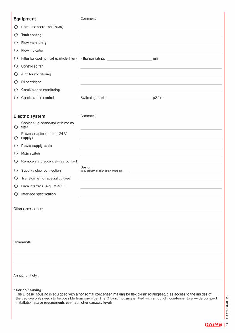
Equipment Comment
○ Paint (standard RAL 7035):
○ Tank heating
○ Flow monitoring
○ Flow indicator
○ Filter for cooling fluid (particle filter) Filtration rating: μm
○ Controlled fan
○ Air filter monitoring
○ DI cartridges
○ Conductance monitoring
○ Conductance control Switching point: μS/cm
Electric system Comment
○ Cooler plug connector with mains filter
○ Power adaptor (internal 24 V supply)
○ Power supply cable
○ Main switch
○ Remote start (potential-free contact)
○ Supply / elec. connectionDesign: (e.g. industrial connector, multi-pin)
○ Transformer for special voltage
○ Data interface (e.g. RS485)
○ Interface specification
Other accessories:
Comments:
Annual unit qty.:
* Series/housing: The D basic housing is equipped with a horizontal condenser, making for flexible air routing/setup as access to the insides of the devices only needs to be possible from one side. The G basic housing is fitted with an upright condenser to provide compact installation space requirements even at higher capacity levels.

E 5.
824.
1.0 /
08.1
6
8
NoteThe information in this brochure relates to the operating conditions and applications described.For applications and operating conditions not described, please contact the relevant technical department.Subject to technical modifications and corrections.
H.I.B Systemtechnik GmbHWinterbruckenweg 30 86316 Friedberg-Derching Germany Tel.: +49 821/ 747 71-4 Fax: +49 821/ 747 71-5594 E-mail: [email protected] Internet: www.h-i-b.de
HYDAC COOLING GMBHIndustriegebiet 66280 Sulzbach / Saar Germany Tel.: +49 6897/ 509-01 Fax: +49 6897/ 509-454 E-mail: [email protected] Internet: www.hydac.com


![Low Firing Temperature Absorption Chiller System - [email protected]](https://static.fdocuments.us/doc/165x107/62039b76da24ad121e4b5f54/low-firing-temperature-absorption-chiller-system-emailprotected.jpg)

