
Chiller Design and Application - Mideahk5.midea.com/images/chiller.pdf · 5 A typical water chiller...
79
Chiller Design and Application New Technology 11/11/2015
Transcript of Chiller Design and Application - Mideahk5.midea.com/images/chiller.pdf · 5 A typical water chiller...

Chiller Design and Application New Technology
11/11/2015
2
• Byron Hamm
– I received a graduate degree in Mechanical Engineering from Iowa State University with a specialty in the aerodynamic design of turbomachinery.
– I worked for over 40 years for a major manufacturer of centrifugal water chillers, having a part in the design of every machine currently produced.
– After retirement from that company, I joined GEA-consulting and have worked with Midea for more than four years as an engineering consultant.
– I continue to find this work fascinating, and have found my consulting work to be a continuing education.

Content
• Chiller system
• Compressor design
• Variable frequency drive
• Falling film evaporator technology
• Future trends in compressor technology
3

4
Chiller Systems
External and internal considerations

5
A typical water chiller consists of -
• Evaporator to provide cooling water to the air conditioning system
• Compressor to provide system pressure differential and refrigerant flow
• Condenser to reject the cooling energy and motor power to the external environment
• Throttle device to reduce refrigerant pressure from condenser pressure to
evaporator pressure
– This is shown schematically on the following slide

6
Typical simple chiller configuration -
Chiller performance is
determined from
simple external
measurements

7
Chiller system cycle diagram - Saturation line
Region of
superheated vapor
Saturated vapor
line
Saturated liquid
line Region
of liquid
and
vapor
mixture
Region of
subcooled liquid

8
Condenser process
Evaporator process
Compression
COP = Qevap / KW input
Throttle process
Chiller performance
is linked to cycle
state points and
component
efficiencies
Chiller system cycle diagram -

9
How can we improve the chiller performance?
– The most obvious method is to increase compressor efficiency and decrease mechanical losses. Compressor design always strives for this
– An additional method is to introduce subcooling into the condenser
– This increases the evaporator Δ H, decreasing the required mass flow for a given capacity, and thus reducing the amount of power required by the compressor
• This is shown on the following slide

10
Performance enhanced by using condenser
subcooling -
Subcooling
Increases ΔHevap and
decreases mevap
decreasing compressor
Wx and increasing COP
Liquid saturation
line

11
• This is easy to accomplish in theory, but more difficult to accomplish in
actual practice.
• In order to achieve subcooling, the subcooler tubes must be contained in
a flooded compartment without a liquid/vapor interface.
• Controlling the liquid level to achieve this at part load is a design
challenge.
• Midea uses an electronic flow control valve which senses condenser
liquid level and regulates the refrigerant flow to ensure that subcooling is
achieved as designed at all load conditions.

12
• Another method to enhance chiller performance is to divide the compression process into two parts and use an economizer cycle as shown on the following slides.
• This enhances chiller performance in two ways:
• The evaporator ΔH is increased even more than with subcooling.
• Injection of the economizer vapor into the compression process slightly reduces the isentropic compression work input.
• This cycle also reduces the amount of discharge superheat that the condenser must remove.
• An economizer is in essence nothing more than a simple vessel to separate the liquid from the vapor at an intermediate pressure.

13
Chiller configuration with economizer -
Pressure
reduction is
done in two
steps
Vapor is
separated
and
injected
into the
compresso
r

14
Chiller system cycle diagram with economizer -
Evaporator process
Condenser process
Economizer –
separates liquid
and vapor Compression
Vapor injection
intercools the
compression process

15
Chiller system cycle diagram with economizer -
Increases ΔHevap and
decreases mevap
decreasing compressor
Wx and increasing COP
Intercooling improves
compression
efficiency

16
• Of course, subcooling can be included into the economizer cycle. This will alter the ratio of vapor to liquid that is provided by the economizer.
• A cycle code is used to evaluate the effects of different amounts of subcooling and the intermediate pressure level of the economizer.
• All Midea two-stage chillers incorporate the economizer cycle with subcooling for maximum chiller COP.
• These also incorporate electronic flow control valves to ensure that the liquid refrigerant is distributed to the various parts of the system according to the design intent. This is especially important at part load conditions.

17
Compressor design
18
Overall approach – • Design for required performance
• Cost reduce the design

19
Design for required performance –
– The overall approach is to lay out the compressor flow path using a meanline design/analysis code, then examine the details using CFD.
– If the CFD analysis finds a problem that requires the redesign of a component, then we go back to the meanline analysis and examine the entire flow path to be sure that all components are still matched.
– The aerodynamic flow path design is done side-by-side with mechanical design to be sure there are no rotordynamic or other mechanical issues, and with review by manufacturing engineers to be sure the design is compatible with the available manufacturing capability.

20
Determine compressor basic flow path -
– Centrifugal compressors are dynamic compression devices – they add energy by increasing flow velocity with the impeller and then diffusing this velocity to raise pressure. There are no enclosed volumes as in a positive displacement compressor (reciprocating, scroll, screw, vane, etc.)
– The governing equation for work input is the Euler equation
– Wx = (U2Vθ 2 – U1Vθ 1)
– where U is the rotor velocity, Vθ is the flow tangential (swirl) velocity, subscript 1 is the rotor inlet and subscript 2 is the rotor exit

21
• Making use of the inlet and exit velocity triangles, this equation may be rewritten
as
Wx = ½( (V22 - V1
2) + (U22 - U1
2) + (V’12 - V’2
2) )
• For a given compressor design, work input is distributed among these components
by the choice of impeller inlet and exit blade angles, rotational speed, inlet relative
Mach number, and internal flow stability considerations.
• Different designers will choose different values for these components of energy
addition according to what they feel is best.
Relative diffusion
Change in radius Change in absolute velocity
22
• Midea uses a meanline design/analysis code to evaluate the best combinations of these variables according to our best engineering judgement.
• Regardless of the detailed design choices that are made, it is clear that work input and flow velocity are closely related.
• For a single-stage compressor, the flow velocities are the result of adding the entire compressor work input in a single impeller. Flow velocities are high and the inevitable result is compressor noise.
• For a two-stage compressor, the work input for each impeller is only one half of the total, so the flow velocities are correspondingly lower. Two-stage compressors are much less noisy than single-stage compressors for this reason.

23
Typical two-stage compressor flow path -
First stage
impeller
Impeller diameter
Vaned/vaneless diffuser
Diffuser diameter
Crossover bend
Vaned return
channel
Second stage
inlet duct
Second stage
impeller
Vaned/vaneless diffuser
Diffuser diameter
Volute/conic diffuser
Impeller diameter

24
Important design decisions –
• Impeller inlet relative Mach number/specific speed?
• Impeller inlet and exit blade angles?
• Impeller relative diffusion/d-factor?
• Stage work input split (impeller diameter ratio)?
• Vaned or vaneless diffusers?
• Pinched diffusers?
• Variable geometry vaneless diffuser?
• Diffuser radius ratio (and first/second difference)?
• Crossover bend diffusion?
• Start/end locations of vanes in vaned return channel?
• Single-vane vs two-vane return channel (second stage IGVs?)?
• Configuration of second stage inlet duct (conservation of rVθ)
• Volute/conic diffuser geometry?

25
In addition to the aerodynamic factors, there may
be geometric constraints as well –
• Impeller hub diameter (power transmission, shaft critical speed)
• Impeller weight/axial spacing (shaft critical speed)
• Bearings and lubricant feed/drain/seal (shaft critical speed)
• Maximum casting diameters due to machine tool limitations
• Minimum volute location due to motor end-winding diameter
• Second stage IGV linkage (if present)
• Thrust balance piston and venting (if present)
• Overall chiller dimension envelope (shipping/application consideration)
• Material size/weight limitations (material handling within workshop)

26
• The meanline design/analysis code is used to systematically study this array
of variables in order to determine the best overall compressor design within
the specified aerodynamic and mechanical constraints. This may include off-
design analysis to estimate range-to-surge, part load performance, etc.
• This process establishes the basic layout of the compressor.
• Only then are detailed CFD studies made of the individual components and
component assemblies.
• If the CFD analysis indicates that some component must be redesigned, then
the meanline design/analysis code is used to rebalance the entire flowpath to
correctly accommodate the redesigned component.

27
The meanline design/analysis code evaluates many flow details

28
• For some refrigerants, the isentropic compression process extends into the
wet region. A very efficient compression may also extend into the wet region.
Assuming dry compression will introduce fluid property errors. The meanline
design/analysis code checks every state point and correctly calculates the
refrigerant properties -
Saturation line
Compression
into wet
region

29
The meanline design/analysis code calculates
impeller disk friction and seal leakage -
The fluid in the cavity rotates
at some fraction of impeller speed
This creates a static
pressure field
Thus, the seal upstream
pressure is known for
seal leakage calculation
The disk friction ΔH Is
added to the leakage
flow and mixed with the
main flow
The disk friction work
input is also added to
the shaft input power
The recirculating
leakage flow is added
to the main flow to
calculate impeller
dimensions

30
The meanline design/analysis code calculates
impeller axial thrust -
The fluid in the cavities rotates
at some fraction of impeller speed
This creates static
pressure fields
Inlet flow has axial
momentum mV
Pressures are integrated
over areas, and all forces
are summed to calculate
axial thrust

Region of high-energy
isentropic core flow (jet)
Region of low-energy boundary
layer flow that accumulates in the
suction surface corner (wake)
31
Impeller exit flow calculation uses the jet-wake model proposed by Japikse –
• This flow mixes to form the impeller exit flow. CFD analysis will give additional insight into the flow within the impeller

32
• The blade profiles used in the vaned diffusers and vaned return channel can be either NACA 65-series or Double Circular Arc -
• Either blade profile type may be specified, as well as the thickness/chord ratio, setting angle, camber, incidence, etc.
• Performance calculation is based on the extensive cascade data and calculation method presented in NASA SP-36, corrected from axial cascade to radial cascade
NACA 65-series blade
Double circular arc blade

33
The meanline design/analysis code has many
available options for cooling the hermetic motor -

34
• These choices may each be analyzed for impact on cycle performance. A common and simple configuration is motor cooling using liquid from the condenser with vapor return to the evaporator. This is shown schematically below -
Liquid from the
condenser is fed into the
motor cooling system
Vapor is returned to the evaporator

35
This motor cooling scheme is simple. But note the
following details –
• This is a flow of refrigerant that is separate from and in addition to the flow required by
the evaporator and condenser for the cooling load.
• Therefore, the compressor must provide this additional flow, and the compressor flow
passage design must be altered accordingly.
• The condenser must have additional surface to condense this additional flow.
– The meanline design/analysis code automatically handles all mass flow requirements
for any selected motor cooling scheme and incorporates these into the design of the
compressor components. In effect, the compressor design is “scaled up” for both
internal seal leakage flows and motor cooling flows.

36
Examples of the interaction of aerodynamic design with other design
requirements

37
• Example 1: The second row of vanes in a vaned return channel are made moveable to serve as second stage IGVs. They bind during operation, preventing rotation -
Second vane in
return channel is
moveable to act as
second stage IGV

38
Problem: – In real life, moving parts require clearances. However, operating pressures
cause deflection of parts. In this case, during operation the vanes bound against the castings and they could not be moved as designed.
Solution: – The first solution was to increase clearance on either side of the vanes.
However, this caused unacceptable performance loss.
– The second solution was to strengthen the vanes with a steel insert inside the shaft (the vanes are an aluminum casting), and to strengthen the vane bearing structure and bolt it to a major structural casting. This solved the problem and actually improved performance because the vane clearance could be further reduced.
– The design team should include aero, mechanical, manufacturing engineers.

39
Example 2: FEA indicates impeller stress exceeds yield strength during the impeller overspeed test -
Stress in impeller
exceeds yield strength
during overspeed test

40
Problem: – FEA analysis indicates that the impellers will have areas of stress
exceeding the yield strength of the material during overspeed tests. Various small changes to the design were not effective in reducing this stress (increased blade thickness, increased fillet radius, etc.). That is because, in hindsight, the root problem was the blade design in the inlet area
Solution: – The impeller vendor suggested a small change in the heat treatment of the
impeller to increase the yield strength significantly. Tests showed that this change did not harm the machinability of the material. This change solved the problem without increasing the cost
– Designs should be done in collaboration with suppliers

41
Example 3: FEA indicates impeller deflection at operating speed -
Deflection of impeller
at operating speed

42
Problem: – FEA analysis indicates that the impellers will deflect at both the tip and
the inlet shroud area at operating speed. This may cause misalignment with the diffuser passage, interference with the surrounding castings, and interference at the inlet seal
Solution: – Location of the impeller should be done so that the deflected tip will align
with the diffuser. Allow clearance around the impeller to avoid interference. Adjust seal clearance to avoid seal interference
– Component design and the design of surrounding components should consider operating deflections due to rotation, temperature, pressure, etc.

43
Example 4: CFD analysis indicates that the flow angle exiting the vaned return channel does not agree with the meanline prediction. Conservation of rVθ means the impeller leading edge will not be aligned with the flow as designed -
Conservation of rVθ
magnifies errors in
flow angle leaving
the return channel
second blade

44
CFD solution for a tandem vane set in the return
channel -

45
Problem: – CFD analysis indicates that the flow leaving the return channel blades will
have an exit angle 2-3⁰ different than indicated by the meanline analysis. The inlet duct is an area of conservation of angular momentum (constant rVθ ). Since there is a significant change in radius between the exit of the return channel blades and the impeller inlet, this error is magnified to be about 6-8⁰. The blades of the second stage impeller were designed to match the flow angles indicated by the meanline analysis.
Solution: – It was decided that the CFD analysis was probably more accurate than the
meanline analysis in this area. The design of the second blade of the return channel was redesigned to provide the flow angle required by the impeller design.
– Various design methods should be compared where practical.

46
Cost reduce the design –
– Consideration should be given at the design stage for ease of component manufacturing, ease of proper assembly, ease of service, and system reliability.
– The number of major castings should be as small as possible consistent with manufacture and assembly, in order to reduce potential leakage joints.
– External piping for the lubrication and motor cooling systems should have minimum connection points, and be designed for easy service while remaining leak tight.
– Carefully review the lubrication system, the heat exchanger designs, and the control system for function and cost.

47
Variable Frequency Drive

48
Variable frequency drive greatly enhances part load performance -
– Variable frequency drive is used to control capacity by adjusting compressor
speed. Head is changed correspondingly. The typical chiller load line has decreasing head as capacity is reduced, so this works well.
– Variable frequency drive can usually be used down to about 50% of design speed before encountering surge (AHRI part load conditions). Below that, control reverts to IGV but requires much less vane closure due to already decreased capacity from speed reduction.
– The plot on the next slide shows a comparison of COP for a chiller using VFD down to 50% load and then IGV control at 25% load, compared to the same chiller using only IGV capacity control.
– The test points are those specified by AHRI for the calculation of IPLV (Integrated Part Load Value).

49
Variable frequency drive greatly enhances part load performance -
IGV capacity control VFD capacity control Calculated IPLV 6.602 10.883

50
Variable frequency drive greatly enhances part load
performance –
• There is a small penalty at full load due to some efficiency loss in the VFD drive.
• There is a large performance gain in the mid-range, the test points that weigh most heavily in the calculation of IPLV.
• The IGV control at 25% load still produces better efficiency because the guide vanes do not have to be closed very much.
• VFD control is optional on Midea gear-drive compressors.
• VFD control is required on all high-speed direct-drive compressors in order to achieve the required compressor speeds.

51
Falling Film Evaporator
Technology

52
What is a falling film evaporator, and how is it different from the
traditional flooded evaporator?

53
Flooded evaporator
Liquid inlet
Filter to remove liquid
droplets
Tube bundle
Dry vapor to compressor
Liquid
distributor

54
Liquid inlet
Dry vapor to compressor
Liquid level in shell,
optimized so that
boiling action just wets
the top tubes for
maximum performance
Large vapor space so
low velocity flow will not
carry liquid droplets into
compressor
Flow is distributed evenly
along the length of the shell
Tube bundle extends to
shell to prevent gas
bypass
Flooded evaporator

55
Falling film evaporator
Liquid inlet
Baffle to remove
liquid droplets
Tube bundle
Dry vapor to
compressor
Liquid distributor
above top row of
tubes
Lower tube bundle
to evaporator any
remaining liquid
Vapor path for
generated vapor

56
Liquid inlet Dry vapor to
compressor
Liquid level in shell
Baffle and vapor space
around distributor designed
to minimize carryover of
liquid droplets to compressor
Vapor must exit the tube
bundle and flow around
the tube bundle
Falling film evaporator

57
How well does this design concept work?
58
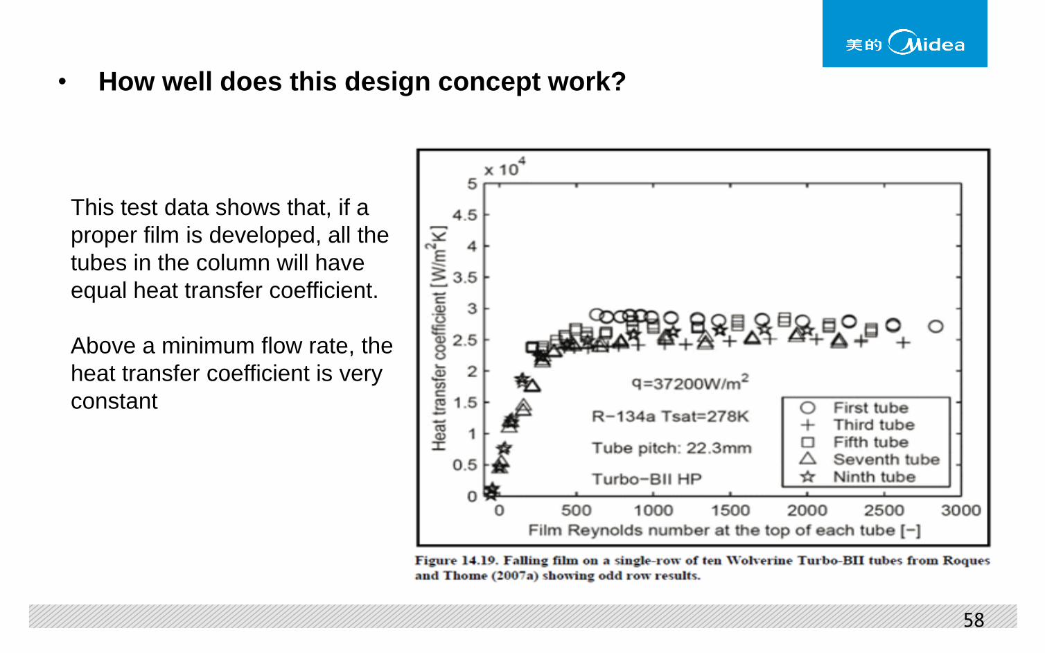
• How well does this design concept work?
This test data shows that, if a
proper film is developed, all the
tubes in the column will have
equal heat transfer coefficient.
Above a minimum flow rate, the
heat transfer coefficient is very
constant

59
• How well does this design concept work?
• This test data illustrates that the heat transfer coefficient can be higher in a
falling film configuration compared to a flooded configuration

60
• How well does this design concept work?
• This test data illustrates that different enhanced tube surfaces will have
different performance characteristics

61
Potential benefits:
– Reduction in working fluid to about 1/3 of flooded evaporator
– Better heat transfer performance
– More uniform heat transfer throughout the evaporator
– Lower approach temperature
– More compact evaporator design
– Superior for oil management (oil holds up in a flooded bundle but drains to the
bottom of a falling film evaporator)

62
Potential disadvantages:
– Less design experience with falling film evaporators
– Uniformity of liquid distribution onto the top tube row is a design challenge
– Less tolerance for undercharging of the chiller
– There is more to performance/cost than boiling heat transfer coefficient
– Does the performance of a falling film evaporator reduce the cost of the tube
surface and refrigerant charge enough to offset the added cost of the distributor
and flow baffles?

63
Charge optimization
• Charge optimization is the same for either evaporator type – find the minimum refrigerant level/flow rate that fully utilizes the heat transfer surface
ITD/ΔT
or
Approach
Refrigerant charge
Optimum charge is
where the curve
flattens out
ITD = inlet water temperature – saturation temperature
ΔT = inlet water temperature – outlet water temperature
Approach = outlet water temperature – saturation temperature

64
Future Trends in
Compressor Technology

65
The compressor world is changing:
Traditional
design
Compact
size
High-speed
gear-drive
Efficiency + IPLV
High-speed
direct-drive
+
VFD
(no gears,
fewer bearings,
permanent magnet
motors)
(variable
speed)
Gen 1
Gen 2
Gen 3

66
Increasing compressor speed drives motor
development:
Traditional
induction motor
Compact
size High-speed
Induction motor
Efficiency
Permanent
Magnet motor
Gen 1
Gen 2
Gen 3
67
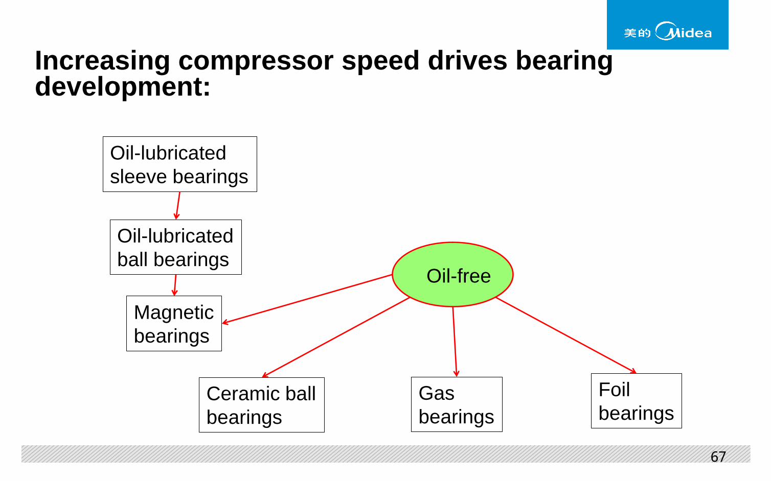
Increasing compressor speed drives bearing development:
Oil-lubricated
sleeve bearings
Oil-lubricated
ball bearings
Magnetic
bearings
Oil-free
Ceramic ball
bearings
Gas
bearings
Foil
bearings

68
Bearing development will result in new requirements:
• New manufacturing methods
• Aerodynamic performance of the compressor due to seal clearance
• Stiffness and rotordynamic characteristics
• System requirements
• Continuing changes to satisfy new requirements of size, cost, efficiency, and oil-free operation
• In the following slides we will briefly review the pros and cons of several bearing types

69
Oil-lubricated sleeve bearings:
• Pro Traditional design
• Simple, reliable, and relatively inexpensive
• Medium clearance requires medium seal clearance and leakage
• Medium load capability
• Con Requires lubrication system – oil pump, filter, heater, cooler, pressure regulator, piping
• Requires oil reclaim system
• Speed limited by increasing bearing losses
• Misalignment issues may require more expensive pivoted-shoe design
• Considered the baseline design for this comparison
• Still perhaps the best solution for the largest lower speed compressors

70
Oil-lubricated ball bearings:
• Pro Well known design methods and operating characteristics
• Low clearance results in low seal clearance and leakage
• Low bearing friction
• Allows higher compressor speed, limited by internal bearing loads
• High load capability, compact bearing system
• Con Requires lubrication system – oil pump, filter, heater, cooler, pressure regulator, piping
• Requires oil reclaim system
• Higher cost than a sleeve bearing
• Lower loss alternative for all compressor sizes within the speed limitation of this bearing type

71
Magnetic bearings:
• Pro Oil free • Known technology, relatively low project risk • No bearing friction • Can be programmed to eliminate balancing and critical speed issues • No compressor speed limit
• Con Requires complex control system • Requires backup bearing system and can be bulky • High clearance results in high seal clearance and leakage • Expensive
• Low-loss oil-free alternative for all compressor sizes and speeds, but
high required clearance will compromise performance of the smaller compressors
• If we separate magnetic bearings from permanent magnet motors, they can be used for higher capacity compressors

72
Refrigerant lubricated ceramic ball bearings:
• Pro Oil free
• Low clearance results in low seal clearance and leakage
• Lower bearing friction than oil lubricated ball bearings
• Higher compressor speeds than oil lubricated ball bearings
• High load capability, compact bearing system
• No oil reclaim system
• Con Requires simplified lubrication system – pump, filter, piping
• Newer technology requiring some project development
• Higher cost than an oil lubricated ball bearing
• Low-loss oil-free alternative for all compressor sizes within the speed limitation of this bearing type

73
Gas (air) bearings (hydrostatic):
• Pro Oil free • Similar in appearance to the simple sleeve bearing, but uses gas
pressure to lift the shaft, not a film generated by shaft rotation • Very low clearance results in very low seal clearance and leakage • Very low bearing friction • No compressor speed limit
• Con Requires external gas source with controlled pressure and temperature • Low load capacity requires larger bearings • New technology requiring significant project development • Very low clearance requires precision manufacture and assembly • Cost unknown but likely to be higher than ordinary sleeve bearings
• Low-loss oil-free alternative for all compressor sizes with no speed limitation • Low clearance would be a special benefit for small-medium compressors

74
Foil bearings (hydrodynamic gas bearings):
• Pro Oil free • Simple concept that requires no lubrication system at all • Higher clearance results in higher seal clearance and leakage • Very low bearing friction • No known compressor upper speed limit
• Con Requires high minimum compressor speed, thereby limiting IPLV • Operating concept requires low loads and very high speeds • New technology requiring significant project development • Requires precision manufacture and assembly • Cost unknown but likely to be very high
• Current state of technology is only for very small very high speed
machines
• Requires extensive development for each application

75
Approximate range of application of bearing technologies:
I believe the newer bearing technologies are best applied at the lower end of the capacity range
for relatively small high-speed direct-drive compressors.

76
Midea has ongoing projects to evaluate each of these technologies

Two-stage Falling-film Centrifugal Chillers
Chiller Plant System Control
Water-cool Falling-film Screw Chillers
Air-cool Falling-film Screw Heat Pump

78

79
Thank You!