Chief Architect 10.08a: sds194.layout DATE CHK'D BY DRWN BY DATE CLIENT JOB NO. SHEET NO. OF SDS-CAD...
5
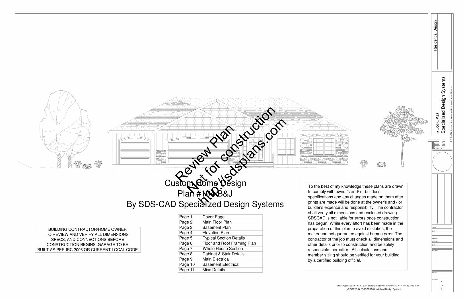
REVISIONS DATE CHK'D BY DRWN BY DATE CLIENT JOB NO. SHEET NO. OF SDS-CAD Specialized Design Systems @COPYRIGHT SDSCAD Specialized Design Systems P O Box 374 Mendon, Utah www.sdscad.com email: [email protected] Residential Design To the best of my knowledge these plans are drawn to comply with owner's and/ or builder's specifications and any changes made on them after prints are made will be done at the owner's and / or builder's expence and responsibility. The contractor shall verify all dimensions and enclosed drawing. SDSCAD is not liable for errors once construction has begun. While every affort has been made in the preparation of this plan to avoid mistakes, the maker can not guarantee against human error. The contractor of the job must check all dimensions and other details prior to construction and be solely responsible thereafter. All calculations and member sizing should be verified for your building by a certified building official. 1 Page 1 Cover Page Page 2 Main Floor Plan Page 3 Basement Plan Page 4 Elevation Plan Page 5 Typical Section Details Page 6 Floor and Roof Framing Plan Page 7 Whole House Section Page 8 Cabinet & Stair Details Page 9 Main Electrical Page 10 Basement Electrical Page 11 Misc Details Custom Home Design Plan #194 B&J By SDS-CAD Specialized Design Systems Note: Paper size 11 x 17 B - size, scale is as stated if printed on 22 x 34 - D size scale is 2X 11 BUILDING CONTRACTOR/HOME OWNER TO REVIEW AND VERIFY ALL DIMENSIONS, SPECS, AND CONNECTIONS BEFORE CONSTRUCTION BEGINS. GARAGE TO BE BUILT AS PER IRC 2006 OR CURRENT LOCAL CODE Review Plan Not for construction http://sdsplans.com
Transcript of Chief Architect 10.08a: sds194.layout DATE CHK'D BY DRWN BY DATE CLIENT JOB NO. SHEET NO. OF SDS-CAD...
REVISIONS
DATE
CHK'D BY
DRWN BY
DATE
CLIENT
JOB NO.
SHEET NO.
OF
SD
S-C
AD
Spe
cial
ized
Des
ign
Sys
tem
s
@COPYRIGHT SDSCAD Specialized Design Systems
P O
Box
374
Men
don,
Uta
h w
ww
.sds
cad.
com
em
ail:
sdsc
ad@
pcu.
net
Res
iden
tial D
esig
n
To the best of my knowledge these plans are drawnto comply with owner's and/ or builder'sspecifications and any changes made on them afterprints are made will be done at the owner's and / orbuilder's expence and responsibility. The contractorshall verify all dimensions and enclosed drawing. SDSCAD is not liable for errors once constructionhas begun. While every affort has been made in thepreparation of this plan to avoid mistakes, themaker can not guarantee against human error. Thecontractor of the job must check all dimensions andother details prior to construction and be solelyresponsible thereafter. All calculations andmember sizing should be verified for your buildingby a certified building official.
1
Page 1 Cover PagePage 2 Main Floor PlanPage 3 Basement PlanPage 4 Elevation PlanPage 5 Typical Section DetailsPage 6 Floor and Roof Framing PlanPage 7 Whole House SectionPage 8 Cabinet & Stair DetailsPage 9 Main ElectricalPage 10 Basement ElectricalPage 11 Misc Details
Custom Home DesignPlan #194 B&J
By SDS-CAD Specialized Design Systems
Note: Paper size 11 x 17 B - size, scale is as stated if printed on 22 x 34 - D size scale is 2X
11
BUILDING CONTRACTOR/HOME OWNERTO REVIEW AND VERIFY ALL DIMENSIONS,
SPECS, AND CONNECTIONS BEFORECONSTRUCTION BEGINS. GARAGE TO BE
BUILT AS PER IRC 2006 OR CURRENT LOCAL CODE
Review
Plan
Not for
cons
tructi
on
http:/
/sdsp
lans.c
om

REVISIONS
DATE
CHK'D BY
DRWN BY
DATE
CLIENT
JOB NO.
SHEET NO.
OF
SD
S-C
AD
Spe
cial
ized
Des
ign
Sys
tem
s
@COPYRIGHT SDSCAD Specialized Design Systems
P O
Box
374
Men
don,
Uta
h w
ww
.sds
cad.
com
em
ail:
sdsc
ad@
pcu.
net
Res
iden
tial D
esig
n
DN
18080
9080
4040
3010
4040
6068
3068 9450 3030 3068 4040
30503050
2668
2668
4068
2668
2668
2668
5068
5068
31068
2268
5030
505060610
3068
5030
5030
2868
5068
D/W
RE
F.
DN
DN
DN
12'-5" x 15'-2"
6'-10" x 6'-1"
2'-2
" x
9'-2
"
10'-8" x 11'-6"
8'-8" x 12'-7"
2'-0
" x
7'-2
"
7'-0" x 12'-6"
16'-7" x 16'-2"
6'-2" x 2'-3"
36'-0" x 23'-5"
15'-7" x 13'-5"
10'-6" x 13'-9"
1668 sq ft
69'-0"
11'-0"16'-0"3'-2"8'-7"17'-0"13'-3"10"
3'-0"4'-9"2'-7"9'-4"5'-1"9"3'-0"9'-6" 4'-0"4'-0"3'-0"
2'-0
"
10'-7
"3'
-2"
54'-0
"
16'-0
"31
'-11"
6'-1
"
6'-0
"5'
-0"
5'-0
"4'
-11"
5'-0
"11
'-0"
5'-0
"6'
-0"
19'-6
"4'
-6"
67'-9
"
14'-5
"5'
-5"
12'-2
"13
'-9"
5'-0
"4'
-0"
5'-5
"1'
-3"
3'-0
"1'
-2"
4'-2
"4'
-0"
4'-0
"
10'-3" 7'-9" 2'-10" 11'-2"
1'-0"3'-0"
4"3'-0" 3'-10"10'-3"
1'-2"5'-0" 1'-7"
69'-0"
13'-0" 24'-0"
2'-0" 9'-0" 2'-0" 3'-0" 18'-0" 3'-0"
GARAGE
MASTER BDRM
MASTER BATH
CLOSET
BEDROOM
CLO
SE
T
BEDROOM
CLO
SE
T
Hal
f Wal
l
MUD ROOM
PANTRY
DECK
WORKSHOP
LIVING AREA
DOOR SCHEDULENUMBER QTY FLOOR SIZE DIMENSIONS DESCRIPTIOND01 6 0 2668 30X80X1 3/8" 3 PANEL DOOR - COLOR BRITE WHITED02 2 0 5068 30X80X1 3/8" HINGEDD03 1 0 6068 72X80" EXT. SLIDER-GLASSD04 1 1 18080 216X96" GARAGE-AT-PANEL - BONED05 1 1 2268 26X80X1 3/8" 3 PANEL DOOR - COLOR BRITE WHITED06 3 1 2668 30X80X1 3/8" 3 PANEL DOOR - COLOR BRITE WHITED07 1 1 2868 32X80X1 3/8" 3 PANEL DOOR - COLOR BRITE WHITED08 2 1 3068 36X80X1 3/4" EXT. 6-PANELD09 1 1 3068 36X80X1 3/4" EXT. HINGED-GLASSD10 1 1 31068 46X80" BIFOLDD11 2 1 5068 30X80X1 3/8" HINGEDD12 1 1 5068 60X80" SLIDERD13 1 1 60610 36X82 1/8X1 3/4" EXT. 6 PANELD14 1 1 6068 36X80X1 3/4" 6-PANELD15 1 1 9080 108X96" GARAGE-AT-PANEL - BONE
WINDOW SCHEDULENUMBER QTY FLOOR SIZE DIMENSIONS DESCRIPTIONW01 1 0 3010 36"X12" LEFT SLIDINGW02 1 0 3030 36"X36" RIGHT SLIDINGW03 4 0 4040 48"X48" RIGHT SLIDINGW04 1 1 3010 36"X12" LEFT SLIDINGW05 1 1 3030 36"X36" LEFT SLIDINGW06 2 1 3050 36"X60" SINGLE HUNGW07 3 1 4040 48"X48" RIGHT SLIDINGW08 3 1 5030 60"X36" RIGHT SLIDINGW09 1 1 5050 60"X60" DBL CASEMENT-LHL/RHRW10 1 1 9450 112"X60" MULLED UNIT
2
SCALE 1/8"=1'
MAIN FLOOR PLANNote: Paper size 11 x 17 B - size, scale is as stated if printed on 22 x 34 - D size scale is 2X
11
VENTING SCHEDULERange Hoods Vent Through RoofAll Bath Fans Vent to ExteriorDryer Vent Vent to Exterior
Ceilings R-38 MinWall above grade R-19 MinWall interior below grade R-13 Min
INSULATION SCHEDULE
Review
Plan
Not for
cons
tructi
on
http:/
/sdsp
lans.c
om
REVISIONS
DATE
CHK'D BY
DRWN BY
DATE
CLIENT
JOB NO.
SHEET NO.
OF
SD
S-C
AD
Spe
cial
ized
Des
ign
Sys
tem
s
@COPYRIGHT SDSCAD Specialized Design Systems
P O
Box
374
Men
don,
Uta
h w
ww
.sds
cad.
com
em
ail:
sdsc
ad@
pcu.
net
Res
iden
tial D
esig
n
4040
3010
4040
26682668
26682668
2668
2668
5068
5068
4040 3030 6068 4040
S
S
WH
WH
UP
35'-8" x 23'-2"
12'-3" x 13'-2"
37'-8" x 15'-8"
10'-5" x 11'-4"15'-2" x 12'-1"
12'-0" x 10'-11"
1736 sq ft
7'-2" x 12'-1"
69'-0"
13'-2 5/8"4'-0"38'-6 3/8"13'-3"
2'-2"6'-0"6'-2 3/8"3'-0"10'-0"4'-0"7'-2" 4'-0"4'-0"5'-2 5/8"
19'-4
"4'
-6"
54'-0
"
14'-5
"5'
-5"
12'-2
"
5'-0
"4'
-0"
5'-5
"1'
-3"
3'-0
"1'
-2"
4'-2
"4'
-0"
4'-0
"
1'-1
0"
54'-0
"
47'-1
1"6'
-1"
10'-2" 4'-0" 3'-6" 14'-4"
69'-0"
13'-0" 24'-0"
GARAGE
LIVING AREA
UTILITY
FAMILY
STORAGE STORAGEBEDROOM
BEDROOM
NAIL BOTTOM TO SILL PLATE.EDGES @12" O.C. IN FIELD.
NAIL W/8d NAILS @6" O.C.4X8 SHT. ON FOUNDATION.
BRACED WALL PANEL
PROVIDE (2) STRAPS FOR B.W.P.ALTERNATE BRACE WALL PANELS
Simpson HPAHD strap location marker
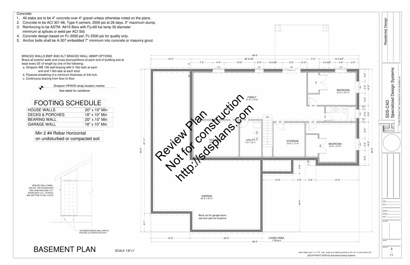
Concrete:1. All slabs are to be 4" concrete over 4" gravel unless otherwise noted on the plans.2. Concrete to be ACI 301-66, Type II cement, 2500 psi at 28 days, 5" maximum slump.3. Reinforcing to be ASTM A615-Bars with Fy=60 ksi lamp 30 diameter
minimum at splices or weld per ACI Std.4. Concrete design based on Fc 2000 psf, Fc 2500 psi for quality only.5. Anchor bolts shall be A-307 embedded 7" minimum into concrete or masonry grout.
3SCALE 1/8"=1'BASEMENT PLAN
Block out for garage doorssee floor plan for locations
Note: Paper size 11 x 17 B - size, scale is as stated if printed on 22 x 34 - D size scale is 2X
11
BRACED WALLS BWP AND ALT BRACED WALL ABWP OPTIONSBrace all exterior walls and cross-stud partitions at each end of building and at least every 25' of length by one of the following: a. Simpson WB 126 wall bracing with 3-16d nails at each
end and 1-8d nails at each stud. b. Plywood sheathing of a minimum thickness of 3/8 inch. c. Continuous bracing from floor to floor
Min 2 #4 Rebar Horizontalon undisturbed or compacted soil
HOUSE WALLS 20" x 10" MinDECKS & PORCHES 18" x 10" MinBEARING WALL 20" x 10" MinGARAGE WALL 18" x 10" Min
FOOTING SCHEDULE
See detail for cantilever
Review
Plan
Not for
cons
tructi
on
http:/
/sdsp
lans.c
om

REVISIONS
DATE
CHK'D BY
DRWN BY
DATE
CLIENT
JOB NO.
SHEET NO.
OF
SD
S-C
AD
Spe
cial
ized
Des
ign
Sys
tem
s
@COPYRIGHT SDSCAD Specialized Design Systems
P O
Box
374
Men
don,
Uta
h w
ww
.sds
cad.
com
em
ail:
sdsc
ad@
pcu.
net
Res
iden
tial D
esig
n
4FRONT ELEVATIONSCALE 1/8"=1'
SCALE 1/16"=1'
RIGHT ELEVATION
ARCHITECTURALASHPHALTSHINGLES
SCALE 1/16"=1'
REAR ELEVATIONSCALE 1/16"=1'
LEFT ELEVATION
6/12 PITCH from left to right8/12 PITCH from front to back
PERSPECTIVE VIEWSNote: Paper size 11 x 17 B - size, scale is as stated if printed on 22 x 34 - D size scale is 2X
11
Exterior Finish to be determined by homeownerand to meet subdivision requirements3 different materials Virticle Fiber Cement SidingStoneFiber Cement Shingles in Eaves
Review
Plan
Not for
cons
tructi
on
http:/
/sdsp
lans.c
om

REVISIONS
DATE
CHK'D BY
DRWN BY
DATE
CLIENT
JOB NO.
SHEET NO.
OF
SD
S-C
AD
Spe
cial
ized
Des
ign
Sys
tem
s
@COPYRIGHT SDSCAD Specialized Design Systems
P O
Box
374
Men
don,
Uta
h w
ww
.sds
cad.
com
em
ail:
sdsc
ad@
pcu.
net
Res
iden
tial D
esig
n
VENT ATTIC PER CODE
2 - 1/2" REBAR
R-38 INSULATION
AS PER FLOOR PLAN
ALUM. SOFFIT & FACIA
8' X 8"FOUNDATIONWATERPROOFTO GRADE
BRICK OR ROCK WITH1/2" AIRSPACE
10" X 20" FOOTINGWITH 2 - 1/2" REBAR
12
SeeElevationsfor Pitch
BEARING WALL AS PER PLAN2 x STUDS @ 16" O.C.
FIN
. FLR
. TO
CLG
.
9'-0"
OVER 30# FELTICE SHIELD 24" UP FROM WALLAND ALL VALLEYS
1'-6"
ASPHALT SHINGLES
PREFABRICATEDTRUSSES @ 24" 0.C.
5/8" PLY. SHEATHING
8"MIN
TRUSS CLIP
1 x 6 FASCIA
FINISH PERELEVATIONS
RAIN GUTTER
2 x 6 BOTTOM PLATE
HOUSE WRAP OVER7/16" PLY. SHEATHING
2 x 6 MUDSILL1/2" x 10"ANCHOR BOLTEMBEDDED 7"INTO CONC.
RIM JOIST
1/2" SHEETROCK
2 x 6 DOUBLE TOP PLATE
R-19 BATT INSULATION
2 x 6 STUD @ 16" O.C.
1/2" SHEETROCK
2 x 11 7/8 TGI JOIST @ 16" O.C.OR AS NOTED ON PLAN
3/4" PLYWOOD SUBFLOOR SCREW & GLUE
6"
8"
20"
6"
10"
4" DRAIN TO DAYLIGHT IN
1/2" REBARSPACED 24" HOR& VERT 4" MINFROM TOP ANDBOTTOM
8" x 24" GRAVEL
7'-8
"
TRUSSES @ 24" 0.C.PREFABRICATED
BASEBOARD
SEE NOTES FORHEADER SIZE
4" CONC. SLAB W/6 x 6 #10WW MESH OR FIBER
4" GRAVEL & 6 MIL VAPOR SEAL
VAULT AS DESIGNATED ON FLOOR PLAN
2x4 INSULATED WALL
5
TYPICAL HOUSE SECTIONSCALE NTS
Note: Paper size 11 x 17 B - size, scale is as stated if printed on 22 x 34 - D size scale is 2X
11
Review
Plan
Not for
cons
tructi
on
http:/
/sdsp
lans.c
om