CHEVRON - Maintenance Heat Exchanger
23
Chevron Corporation 1000-1 March 1994 1000 Maintenance Abstract This section discusses the major maintenance requirements for heat exchangers. This includes repairing and replacing body flanges, body flange gasketing and torquing considerations, bundle replacement and repair, tube leak repairs, shell repairs, and on-line leak repairs. Contents Page 1010 Replacing Versus Repairing Body Flange Leaks 1000-3 1011 Causes of Flange Leaks 1012 Criteria for Flange Replacement 1013 Analyzing Existing Flanges 1014 Replacing Body Flanges 1015 Repairing Existing Flanges 1020 Flange Gasketing and Torquing 1000-10 1021 Choosing the Proper Gasket 1022 Reasons to Torque Bolted Enclosures 1023 Torque Calculations 1024 Developing a Torquing Procedure 1030 Bundle Retubing, Replacement, or Repair 1000-11 1031 General Considerations for Opening Up an Exchanger 1032 Considerations for Retubing, Repairing, or Replacing the Bundle 1033 Bundle Repair Worksheet 1040 Tube Leak Repairs 1000-15 1050 Shell Repairs 1000-15 1060 Online Leak Repairs 1000-15 1061 Types of Online Repairs 1062 Temporary Online Leak Repair Procedures
-
Upload
ramirezisaac6843 -
Category
Documents
-
view
520 -
download
22
Transcript of CHEVRON - Maintenance Heat Exchanger

rs.
l
1000 Maintenance
AbstractThis section discusses the major maintenance requirements for heat exchangeThis includes repairing and replacing body flanges, body flange gasketing and torquing considerations, bundle replacement and repair, tube leak repairs, shelrepairs, and on-line leak repairs.
Contents Page
1010 Replacing Versus Repairing Body Flange Leaks 1000-3
1011 Causes of Flange Leaks
1012 Criteria for Flange Replacement
1013 Analyzing Existing Flanges
1014 Replacing Body Flanges
1015 Repairing Existing Flanges
1020 Flange Gasketing and Torquing 1000-10
1021 Choosing the Proper Gasket
1022 Reasons to Torque Bolted Enclosures
1023 Torque Calculations
1024 Developing a Torquing Procedure
1030 Bundle Retubing, Replacement, or Repair 1000-11
1031 General Considerations for Opening Up an Exchanger
1032 Considerations for Retubing, Repairing, or Replacing the Bundle
1033 Bundle Repair Worksheet
1040 Tube Leak Repairs 1000-15
1050 Shell Repairs 1000-15
1060 Online Leak Repairs 1000-15
1061 Types of Online Repairs
1062 Temporary Online Leak Repair Procedures
Chevron Corporation 1000-1 March 1994

1000 Maintenance Heat Exchanger and Cooling Tower Manual
1070 References 1000-21
March 1994 1000-2 Chevron Corporation

Heat Exchanger and Cooling Tower Manual 1000 Maintenance
rn.
sket.
o such
d
o- in
is tially
not
its
e
1010 Replacing Versus Repairing Body Flange Leaks
1011 Causes of Flange LeaksExchanger flange leaks are a major environmental, safety, and economic conceFlange leaks are generally caused by one or more of the following:
Wrong Gasket Selection• Gasket is too wide, there is not enough bolting to properly compress the ga
• Gasket is too narrow, causing gasket alignment and seating problems.
• Gasket seating surface is not compatible with the gasket. It can be either tosmooth for gaskets such as composition asbestos, or too rough for gasketsas solid metal or metal jacketed.
• Gasket is the wrong material for the application (i.e., stock, temperature, anpressure.)
Poor Flange Design• Flanges do not have enough thickness to withstand the operating and hydr
static test pressures without leaking. (See Section 530 for more informationthis area.)
• Bolts have been torqued past their maximum stress in trying to stop leaks.
• Flanges were deformed or rotated in the process of trying to stop leaks. Thcauses improper gasket seating and is indicated by a gasket that is substanthinner on the outside diameter than on the inside diameter.
• Flanges do not mate up well initially.
Figure 1000-1 illustrates the gasket seating problems related to flanges that arealigned properly or are rotated.
Weather• Rain storms can deform uninsulated flanges and unseat the gasket.
Mechanical Damage• Gasket was damaged during installation.
• Flange surface was scratched or gouged during maintenance.
• Poor torquing procedure caused uneven compression of the gasket aroundcircumference.
Corrosion• Flange is so extensively corroded there is not enough gasket seating surfac
left.
Chevron Corporation 1000-3 March 1994

1000 Maintenance Heat Exchanger and Cooling Tower Manual
Fig. 1000-1 Flange Alignment Problems (1 of 3)
March 1994 1000-4 Chevron Corporation

Heat Exchanger and Cooling Tower Manual 1000 Maintenance
Fig. 1000-1 Flange Alignment Problems (2 of 3)
Chevron Corporation 1000-5 March 1994

1000 Maintenance Heat Exchanger and Cooling Tower Manual
Fig. 1000-1 Flange Alignment Problems (3 of 3)
March 1994 1000-6 Chevron Corporation

Heat Exchanger and Cooling Tower Manual 1000 Maintenance
tch the
e
he ess,
et, or
of
ger
s is
• Gasket material is not resistant to the process fluid.
Process Upsets• Excessive temperatures or pressure surges can unseat the gasket and stre
bolts.
1012 Criteria for Flange ReplacementConsider replacing flanges under the following conditions:
• Flange is near the ASME tmin for the operating conditions.
• Flange is so badly corroded the repair costs are greater than or equal to threplacement costs.
• Flange is rotated causing the gasket not to seat properly.
• The right gasket cannot be used because of flange configuration problems.
• Flange is a chronic leaker. ASME flange design may not be adequate.
1013 Analyzing Existing FlangesThe reasons for flange leakage and the decision to repair, insulate, or replace tflanges can be determined by visual inspection of the flange, by comparing theexisting flange thickness against the ASME and Company recommended thicknand by relating the onset of leakage to some significant event (i.e., startup, upsrain storm).
InspectionThe following inspection techniques can be used to analyze existing flanges:
• Check for flange rotation. Are the flanges “metal-to-metal” around any part the circumference?
• Inspect the gasket. See Figure 1000-2 for problems that examination of thegasket can point out.
• Inspect the gasket seating surface for damage or corrosion.
• Measure the flange thickness to determine if it is at or below ASME tmin.
• Measure the critical dimensions and compare them with the original exchanand TEMA tolerances. Figure 1000-3 can be used for this purpose.
The following procedure can be used for analyzing existing flanges:
• Check the flange thickness versus ASME tmin and Chevron Method tmin using the PCFLANGE program for the existing gasket design. If existing thicknesless than ASME tmin then flange will need to be replaced.
Chevron Corporation 1000-7 March 1994

1000 Maintenance Heat Exchanger and Cooling Tower Manual
the
• Determine if a different gasket will solve the problem. Use Figure 500-15, inSection 540, to choose the optimum gasket. Determine the ASME tmin for the new gasket. If the existing flange is not thick enough to properly compress gasket consider replacing the flange.
Fig. 1000-2 Determining the Cause of Leakage by Examining the Gasket
Observation Causes and Possible Remedies
Gasket badly corroded Select replacement material with improved corrosion resistance.
Gasket extruded excessively Select replacement material with better cold flow prop-erties; select replacement material with better load carrying capacity, i.e., more dense. This could also indi-cate excessive bolt load or insufficient gasket width.
Gasket grossly crushed Select replacement material with better load carrying capacity; provide means to prevent crushing the gasket by use of a stop ring or re-design of flanges. This could also indicate excessive bolt load or insuffi-cient gasket width.
Gasket mechanically damaged due to overhang of raised face or flange bore.
Review gasket dimensions to insure gaskets are proper size. Make certain gaskets are property centered in joint.
No apparent gasket compression achieved. Select softer gasket material. Select thicker gasket material. Reduce gasket area to allow higher unit seating load.
Gasket substantially thinner on O.D. than on I.D. This is indicative of excessive “flange rotation” or bending. Alter gasket dimensions to move gasket reac-tion closer to bolts to minimize bending movement. Provide stiffness to flange by means of back-up rings. Select softer gasket material to lower required seating stresses. Reduce gasket area to lower seating stresses.
Gasket unevenly compressed around circumference This results from improper bolting-up procedures. Make certain proper sequential bolt-up procedures are followed. Non-uniform thermal stresses may also be a problem.
Gasket thickness varies periodically around circumference
This is indicative of “flange bridging” between bolts or warped flanges. Provide reinforcing rings for flanges to better distribute bolt load. Select gasket material with lower seating stress. Provide additional bolts if possible to obtain better load distribution. If flanges are warped, re-machine or use softer gasket material.
March 1994 1000-8 Chevron Corporation
Heat Exchanger and Cooling Tower Manual 1000 Maintenance
re:
for
r-
1014 Replacing Body FlangesIf it is determined that flange replacement is needed, use the following procedu
• Choose optimal gasket for the service conditions required. See Section 540guidance in this area.
• Use the PCFLANGE program to determine the new flange thickness. Geneally flanges designed to the Chevron method will be thicker than the ASME
Fig. 1000-3 Exchanger Flange Tolerances (Courtesy of TEMA)
Chevron Corporation 1000-9 March 1994

1000 Maintenance Heat Exchanger and Cooling Tower Manual
the
ded im
n to
n es ace
ust
he
flanges. See Section 530 and Appendix G for more detailed discussions of design methods.
• Use integral body flanges if possible.
• Follow ASME Code procedures for replacing and inspecting the flanges.
1015 Repairing Existing FlangesIf flange leakage is caused by damage to the gasket surface or a partially corrogasket surface, the flanges can normally be repaired by weld build-up and/or skcutting. Flanges that are close to ASME tmin should be built up with weld material before skim cutting the surface in order to avoid losing flange thickness.
Flanges that are designed in accordance with Appendix G can be skim cut dowtmin as determined by Appendix G without a problem because these flanges areusually much thicker than ASME flanges. However, skim cutting to thicknessesbelow Appendix G tmin may result in leakage.
The type of skim cut depends on the gasket selected. For example, compositioasbestos gaskets work best with a 250 RMS surface because the deeper groov“bite into” the gasket better. Refer to Section 540 and Figure 500-15 for the surfrequirements for various types of gaskets.
It is very important that all repairs be accompanied by a welding procedure if needed and a technical drawing showing the dimensions and tolerances that mbe met after the repair is complete.
1020 Flange Gasketing and Torquing
1021 Choosing the Proper GasketChoosing the proper gasket is the critical first step in leak-free flange design. Tgoal for existing and new exchangers is to provide a suitable gasket that can beadequately compressed without overstressing the flange.
Refer to Section 540 and Figure 500-15 for guidance on gasket selection.
1022 Reasons to Torque Bolted EnclosuresTorquing procedures accomplish the following:
• They prevent overtorque and the resulting flange rotation.
Surface Designation Appearance
250 RMS Relatively deep grooves
125 RMS Fairly smooth
63 RMS Smooth appearance
March 1994 1000-10 Chevron Corporation

Heat Exchanger and Cooling Tower Manual 1000 Maintenance
ge
r
oint
d t may
-
an
nd.
ure
ere
an
• They prevent cocking the flange faces or pinching the gasket due to unevenbolt loading.
1023 Torque CalculationsFigure 1000-4 is a torque calculation procedure. Using this procedure, you candetermine the torque required to pass hydrotest and reseat in service if the flandoes not deform.
1024 Developing a Torquing ProcedureRefer to Appendix G for flange design and Section 532 for boltup procedures folarge flanges.
After initial torquing, the exchanger should be retorqued to 100% of Tf (see Figure 1000-4) within 4 hours at ambient temperatures to compensate for any jrelaxation.
High temperature applications or applications that have had a history of chronicleakage, should be retorqued at 100% of Tf after 24 hours at operating pressure antemperature. This is to compensate for bolt, flange, or tubesheet relaxation thaoccur.
☞ Caution The allowable bolt/flange stress will decrease with increasing temperature.
1030 Bundle Retubing, Replacement, or RepairThis section lists the major considerations for determining (1) whether to open exchanger and (2) whether to retube, replace, or repair a tube bundle. It also includes a worksheet for use in making these decisions before a plant turnarou
1031 General Considerations for Opening Up an ExchangerIt is very expensive to open an exchanger for inspection and repairs. Also, for exchangers that are operating well, opening them unnecessarily may cause futproblems. Therefore, it is very important to have an organized procedure for making decisions. This is especially important going into a plant turnaround wha large number of exchangers will need to be investigated.
The following list of considerations can be used to help determine when to openexchanger.
• Is the exchanger leaking internally or externally?
• Does the unit need recertification?
This is usually a concern only for steam generators, which require periodic state inspection and certification.
Chevron Corporation 1000-11 March 1994

1000 Maintenance Heat Exchanger and Cooling Tower Manual
Fig. 1000-4 Torque Calculation Procedure (1 of 2)
A. Nomenclature
Ab = Cross sectional root area of one bolt (in2) (see Figure G-4, Appendix G)
bo = Gasket seating width (N/2) (inches) (see Figure G-3, Appendix G)
b = Effective gasket seating width (inches) (see Figure G-3, Appendix G): b = bo if bo 0.25"; b = (bo)/2 if bo 0.25"
D = Nominal diameter of bolt or stud (inches)
Dr = Bolt diameter at root of threads (inches)
G = Diameter at location of gasket load reaction (inches):
G = (O.D. + I.D.)/2 if bo 0.25
G = O.D. - 2b, if bo > 0.25
Pd = Design pressure for your application (psig)
Ph = Hydrotest pressure for your application (psig)
Lp = Total length of pass partition gaskets (in.) (Lp = G for one pass partition)
m = Gasket factor (Refer to Figure G-2, Appendix G or ASME Code, Section VIII, Division 1, Appendix 2, Table 2-5.1)
n = Number of bolts
N = Contact width of the gasket (inches) (see Figure G-3, Appendix G).
S = Bolt stress (psi)
T = Torque (ft-lbs)
y = Gasket seating stress (psi) (Refer to Figure G-2, Appendix G or ASME Code, Section VIII, Division 1,Appendix 2, Table 2-5.1)
W1 = Bolt load to pass hydrotest, lbf
W2 = Bolt load for operating conditions, lbf
Note These calculations can be performed using the PCFLANGE program. (See Appendix H)
March 1994 1000-12 Chevron Corporation

Heat Exchanger and Cooling Tower Manual 1000 Maintenance
r- .
and
• Is the exchanger performance satisfactory?
In other words, does the U-value or DP indicate fouling or internal damage.
• Based on this bundle’s history and the history of similar bundles in similar services, will the bundle last until the next turnaround?
Accurate inspection records are important in making this decision.
• Can exchanger be cleaned on the run?
Isolating an exchanger and cleaning it with the surrounding equipment opeating entails significant safety and operating problems. This is usually doneonly if the exchanger and piping were designed to allow for online cleaning
• Can the unit be chemically cleaned?
Light uniform fouling may be chemically cleanable. Locally plugged exchangers cannot be chemically cleaned. Chemical cleaning is expensiveall of the environmental and safety implications should be considered first. Section 700 of the Corrosion Prevention Manual, Book 1, discusses chemical cleaning in more detail.
B. Calculating a Torque Value:
Find bo bo = (in)
Find b (see Nomenclature) b = (in)
Calculate G (see Nomenclature) G = (in)
Find Lp Lp = (in)
Find m m = (in)
Find y y = (psi)
Calculate W1 and W2:
W1 = 0.785 G2Ph + 2b(3.14 G + Lp) m Ph W1 = (lb)
W2 = 0.785 G2Pd + b(3.14 G + Lp) y W2 = (lb)
W = Larger of W1 or W2 W = (lb)
Calculate bolt stress, S = W/(Ab ⋅ n) S = (psi)
Calculate Torque
T = 0.013 S(Dr)3 T = (ft-lb)
Round to nearest multiple of 25 for
final torque Tf = (ft-lb)
Fig. 1000-4 Torque Calculation Procedure (2 of 2)
Note These calculations can be performed using the PCFLANGE program. (See Appendix H)
Chevron Corporation 1000-13 March 1994

1000 Maintenance Heat Exchanger and Cooling Tower Manual
t
e The
w
lug-e
be it is
a-
st e of
m e-cess
is
1032 Considerations for Retubing, Repairing, or Replacing the BundleAssuming the bundle is leaking or, based on past experience, that it will not lasuntil the next turnaround, then some repairs will need to be made. The followingareas need to be considered before deciding on the extent of repairs.
• Is bundle nearing its historical life?
If a bundle is leaking and it is not approaching its historical life, then a failuranalysis should be performed to determine if design changes are required.best way to determine the cause of failure is to pull the leaking tubes and inspect them.
• Can tubesheet be reused?
Normally, a tubesheet can only be used two or three times before it can nolonger have a tube rolled into it. If a tubesheet cannot be reused, then a nebundle will be necessary.
• Can leaking tubes be plugged or replaced?
Individual leaking tubes can be the sign of a much larger problem. Simply pging or replacing leaking tubes may be setting yourself up for another failurbefore the next shutdown.
The leaking tube should be pulled and inspected to determine the cause offailure. The position of the failed tube relative to baffles and nozzles shoulddetermined and recorded. This can help identify the cause of the failure. If not obvious that repairing or replacing the tube will ensure a sound bundle,then the bundle should be retubed or replaced.
Sometimes, all of the leaks may be in one part of the bundle. In this case, adesign change (i.e., replacing tubes with solid rods, changing inlet configurtion, etc.) may eliminate the problem.
• If a new bundle is required, should it be redesigned?
Simple design changes may substantially improve a bundle’s operation andservice life. If a bundle needs to be retubed or replaced, the incremental cofor making these design changes may not be very high. However, the causthe bundle deterioration should always be identified and process changes considered along with design changes.
Some examples of bundle configuration changes that may improve the long terheat transfer or bundle life are listed below. (Discuss these changes and improvments with a CRTC heat transfer specialist or the CRTC Process Design or ProConsultation groups.)
• Change inlet impingement design to eliminate tube vibration wear.
• Plug tubes to increase tube velocity. (This improves heat transfer if fouling significant.)
March 1994 1000-14 Chevron Corporation

Heat Exchanger and Cooling Tower Manual 1000 Maintenance
nd
last gi-
t of
e y e
oth d er
re
ation. t ally h
• Change shell side pass configuration and baffling to improve heat transfer adecrease fouling.
• Use different materials that will increase the bundle reliability and life. (As ageneral rule, even in corrosive services such as sea water, a bundle shouldat least two operating runs. Contact the CRTC Materials and Equipment Enneering Unit for help in this area.)
• Change from floating head to U-tube design. (See Sections 450 and 520.)
1033 Bundle Repair WorksheetFigure 1000-11 is a worksheet that can be used prior to taking an exchanger ouservice to make a sound decision as to the extent of repairs required.
Note Figure 1000-11 is an 11 × 17 foldout at the end of this section.
1040 Tube Leak RepairsRoll leaks should be repaired by rerolling (never by driving a drift pin or pin wrench in the tube.) Caution shall be taken not to overexpand the tubes. See Section 520 for guidelines on rolling tubes.
Defective tubes should be plugged off. The inside surface of the tubes should bthoroughly cleaned before installing plugs. The tube ends that are worn or badlimpinged should be removed, and a new tube should be installed or a short tubstub should be installed before plugging with a tapered plug.
1050 Shell RepairsThin areas of shells can be weld repaired. All weld repairs must be ground smofor bundle access. If extensive weld repairs are required, cutting out the corrodearea and installing a butt-welded patch may be necessary. In either case, whethmaking weld repairs or replacing part of the shell, precautions must be taken toprevent out-of-roundness.
If repairs are required, it must be remembered that exchanger shells are pressuvessels and fall within the scope of the ASME Code. Refer to the Pressure Vessel Manual for more information on ASME Code repair procedures.
1060 Online Leak RepairsThere are times when repairs must be made to an exchanger while it is in operNormally, this is only when the exchanger cannot be taken out of service withourisk to personnel or equipment or without major expense. These repairs are usuexternal leak repairs and should only be undertaken with the utmost caution witthe appropriate operating, engineering, and maintenance review.
Chevron Corporation 1000-15 March 1994

1000 Maintenance Heat Exchanger and Cooling Tower Manual
b-
use
k nge
h
e.
the ming
er-er his
d d for al
ted
e
ur-
1061 Types of Online RepairsOnline repairs that can be made include:
1. Retorquing flanges
This usually involves tightening all of the bolts. Follow appropriate torquing procedures to prevent worsening the problem.
Belleville Spring Washers have sometimes been used to solve leakage prolems caused by differential thermal expansion. It is usually necessary to replace the bolts one at a time when doing this. Appendix H discusses the of Belleville Washers in more detail.
Note that torquing the bolts over their code allowable stress may stop a leatemporarily. However, this may cause permanent deformation of the flangesuch that, (1) the flange may leak on the next thermal cycle, and (2) the flamay need major repairs or replacement on the next shutdown.
2. Tapping the flange and pumping in sealant between the flange faces at higpressure.
3. Installing a ring around two flanges and pumping in sealant at high pressur
Repairs 2 and 3 are only temporary fixes and can be very expensive. Permanent repairs must be made during the next turnaround. The work required to removeleak sealing compound in order to repair the exchanger can also be time consuand costly. The next section discusses these temporary repairs in more detail.
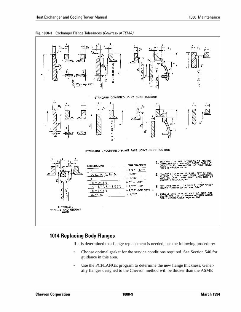
1062 Temporary Online Leak Repair ProceduresFigure 1000-5 can be used by operations, engineering and maintenance to detmine the types of repairs needed, and also used as a checklist to verify all propprecautions have been taken and all necessary reviews and approvals made. Tform was developed at the Richmond Refinery.
Leak Sealing ContractorsNormally, special leak sealing contractors provide personnel who are trained anqualified with regard to the equipment, material, and techniques commonly useonline leak sealing. Sealing compounds must be resistant to the leaking materiand suitable for operating pressure and temperature.
Clamps, boxes, and other enclosures used for leak sealing are normally fabricaand installed by the leak sealing contractor.
Safety Considerations• The contractor must understand all local safety regulations applicable to th
work.
• The contractor must understand the nature of the leakage and why it is occring in order to use a safe procedure.
March 1994 1000-16 Chevron Corporation
Heat Exchanger and Cooling Tower Manual 1000 Maintenance
Fig. 1000-5 Example of a Leak Sealing Checklist (1 of 2)
Chevron Corporation 1000-17 March 1994

1000 Maintenance Heat Exchanger and Cooling Tower Manual
he
g
ting
ay ving
king t. It
• All safety precautions and protective clothing required should be listed on tLeak Sealing Checklist (Figure 1000-5) and reviewed with the contractor.
• A plant Safety Operator must be present during the execution of leak sealinwork on plant equipment.
• Sealant injections should not be made into any pressure relief valve or bursdisc if the sealant could obstruct their free and full discharge requirements.
• If a clamp or enclosure was installed prior to 1984, the sealant compound mcontain asbestos. Normal asbestos procedures should be used when remothese enclosures. Refer to Insulation and Refractory Manual, Section 500.
Special Design Considerations• Stud bolts, packing studs, valve stems, etc., that have been exposed to lea
steam or boiler feedwater above 140°F are subject to caustic embrittlemen
Fig. 1000-5 Example of a Leak Sealing Checklist (2 of 2)
March 1994 1000-18 Chevron Corporation

Heat Exchanger and Cooling Tower Manual 1000 Maintenance
” to
ra- ials
plied s of by ns
cific
rill
ing
0 psi
ess
is sometimes recommended to replace studs with Teflon coated “blue boltsresist caustic cracking.
• B-7 studs are also subject to sulfide cracking (H2S sour water) at temperatures below 200°F. Stainless steel bolts are subject to chloride cracking at tempetures above 150°F and caustic cracking above 140°F. Consider using B7Mbolts in these situations. Consult CRTC Technical Standards Team’s MaterDivision for more information if necessary.
• Extra caution should be exercised if excessive external pressure can be apby sealant injection on cylindrical or spherical shapes. Collapsing pressurethin-walled cylindrical members, based on an empty line, can be calculatedformulas in the Standard Handbook for Mechanical Engineers. All calculatioshould be approved by the appropriate engineering supervisor.
Repair ProceduresFigures 1000-6 through 1000-9 give the general work procedures to follow depending on the specific situation. These procedures can be adapted to a spejob and attached to the work order.
• Figure 1000-6 Procedure for Flange Joints with Less than 3/8" Gap Using Dand Tap Method
• Figure 1000-7 Procedures for Sealing Flange Leaks with Use of Injection RAdaptor
• Figure 1000-8 Procedures for Sealing Flange Leaks on Pressures below 35with Lug Adaptors
• Figure 1000-9 Procedures for Sealing Flange Joints with Gap Width in Excof 3/8"
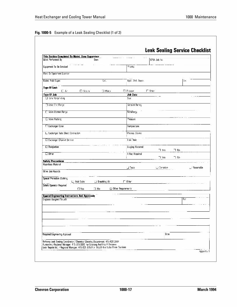
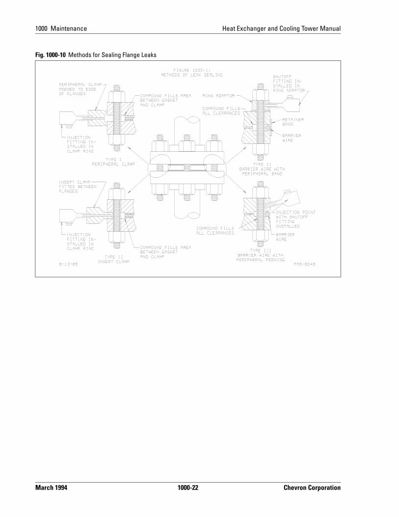
• Figure 1000-10 Methods for Sealing Flange Leaks
Chevron Corporation 1000-19 March 1994

1000 Maintenance Heat Exchanger and Cooling Tower Manual
(1) Refer to Figure 1000-10, Type II
Fig. 1000-6 Procedure for Flange Joints with Less than 3/8" Gap Using Drill and Tap Method
1. When possible, change out studs one at a time with the use of boiler clamps.
2. Drill 3/16-inch diameter holes between studs approximately 4 inches apart from outer circumferential flange surface at an angle to break through into gap area at bolt circle. (Outside stress area of flange.)
– On full surface gaskets and metal to metal joints, drilling is done into stud clearance areas.
3. Drill out hole to 5/16-inch diameter by 1/2-inch deep.
4. Tap out holes to 3/8-inch NC thread.
5. Install shut-off adaptors in tapped holes.
6. Insert tight fitting wire into gap around flange.
7. Lightly peen lock edge of flanges over wire with a bull nose peening chisel approximately 1/8-inch over gap size.
8. Starting 180 degrees from leak blow area, inject thermosetting compound around flange in both directions until gap area and stud clearance areas are full with final injection on shut-off adaptor directly over leak area.
9. After appropriate cure time depending on the temperature for steam, water, and air services under 600 psi, shut-off adaptors are removed and set screw plugs installed.
10. On pressures above 600 psi and on chemical services, shut-off adaptors are left in place.
Fig. 1000-7 Procedures for Sealing Flange Leaks with Use of Injection Ring Adaptor(1)
1. Change out studs one at a time along with installing ring adaptor under the nut of each stud.
– One ring adaptor on thin, narrow gap flanges
– Two ring adaptors (each end of stud) on thicker, wider gap flanges
2. Insert tight-fitting wire in gap and peen lock edge of flange over wire to retain it.
3. Install shutoff adaptors into injection ring adaptors.
4. Starting on adaptors farthest away from leak, inject all adaptors with thermosetting compound closing after each injection, working around flange in both directions until flange is full and leak is stopped.
5. On steam, water, and air service with pressure below 600 psi:
– After proper curing time, shutoff adaptors are removed from ring adaptors and set screw plugs are installed.
6. On pressures above 600 psi and chemical service, shutoff adaptors remain in place.
Fig. 1000-8 Procedure for Sealing Flange Leaks on Pressures Below 350 psi with Lug Adaptors
1. Change out studs one at a time with the use of boiler clamps.
2. Install injection adaptor on stud nearest leak area for exhaust port and one adaptor 180 degrees from leak area.
3. Insert tight-fitting wire in gap and peen lock edges of flange over wire to retain it.
4. Start injection of thermosetting compound through adaptor furthest away from the leak.
5. After stud is full, remove adaptor and retighten stud and move to adjacent studs working around flange in both directions until all studs are injected.
6. After injection of last stud, leave injection gun on adaptor until proper curing time allows the removal of the last adaptor.
March 1994 1000-20 Chevron Corporation

Heat Exchanger and Cooling Tower Manual 1000 Maintenance
1070 References
(1) Refer to Figure 1000-10, Type I
1. Appendix G, “Heat Exchanger Body Flange Calculations.”
2. Appendix H, “PCFlange Program User’s Guide.”
3. ASME Code, Section VIII, Division 1. Latest ed.. Appendix S and 2.
4. ANSI B16.5, Latest ed. “Steel Pipe, Flanges and Flanged Fittings.”
5. TEMA (Tubular Exchanger Manufacturers Association), Latest ed.
6. Lamons Gasket Handbook, Latest ed.
Fig. 1000-9 Procedures for Sealing Flange Joints with Gap Width in Excess of 3/8”(1)
1. Contractor will engineer and fabricate flange clamp.
2. When possible change out stud one at a time.
3. Install shutoff adaptors in flange clamp.
4. Install clamp in gap of flange.
5. Peen lock both flanges to clamp joints.
6. Inject thermosetting compound through shutoff adaptors starting at the point farthest away from leak working around the flange in both directions until flange joint is completely full and leak is stopped.
7. On steam, water, and air services with pressures below 600 psi:
– After proper compound curing time shutoff adaptors are removed and set screw plugs installed.
8. On pressures over 600 psi and chemical service, shutoff adaptors are left in place.
9. Depending on flange dimensions, temperature, and special circumstances, ring adaptor or drill and tap tech-niques may be used in conjunction with this procedure.
Chevron Corporation 1000-21 March 1994
1000 Maintenance Heat Exchanger and Cooling Tower Manual
Fig. 1000-10 Methods for Sealing Flange Leaks
March 1994 1000-22 Chevron Corporation

1000 Maintenance
March 1994
Heat Exchanger and Cooling Tower Manual
Chevron Corporation 1000-23
Fig. 1000-11 Bundle Repair Worksheet