Chen Qinghua DTIC
14
AD-A256 908 " ' FOREIGN AEROSPACE SCIENCE AND TECHNOLOGY CENTER ABLATIVE THERMAL PROTECTION STRUCTURE DESIGN OF BALLISTIC REENTRY SPACECRAFT by Chen Qinghua DTIC Approved for public release, Distribution unlimited. 92-27892
Transcript of Chen Qinghua DTIC
AD-A256 908 " '
FOREIGN AEROSPACE SCIENCE ANDTECHNOLOGY CENTER
ABLATIVE THERMAL PROTECTION STRUCTURE DESIGN OF BALLISTIC REENTRY SPACECRAFT
by
Chen Qinghua
DTIC
Approved for public release,Distribution unlimited.
92-27892

FASTC-ID(RS)T-0623-92
HUMAN TRANSLATION
FASTC-ID(RS)T-0623-92 8 October 1992
ABLATIVE THERMAL PROTECTION STRUCTURE DESIGN OFBALLISTIC REENTRY SPACECRAFT
By: Chen Qinghua
English pages: 11
Source: Unknown; pp. 44-48
Country of origin: ChinaTranslated by: Leo Kanner Associates
F33657-88-D-2188Requester: FASTC/TATV/Ernest S. MullerApproved for public release; Distribution unlimited.
THIS TRANSLATION IS A RENDITION OF THE ORIGINAL PREPARED BY:FOREIGN TEXT WITHOUT ANY ANALYTICAL OR EDITO-RIAL COMMENT STATEMENTS OR THEORIES ADVO- TRANSLATION DIVISIONCATED OR IMPLIED ARE THOSE OF THE SOURCE AND FOREIGN AEROSPACE SCIENCE ANDDO NOT NECESSARILY REFLECT THE POSITION OR TECHNOLOGY CENTEROPINION OF THE FOREIGN AEROSPACE SCIENCE AND WPAFB, OHIOTECHNOLOGY CENTER.
FASTC-ID(RS)T-0623-92. Date 9 ontnhpr 19

GRAPHICS DISCLAIMER
All figures, graphics, tables, equations, etc. merged into thistranslation were extracted from the best quality copy available.
Acesseion For 7
DTIC TABU Unannouncned 3Justification
By,ýt
Distribution/kC.
Availability Ccde$r- Avail and/or
S _peal
Oi

ABLATIVE THERMAL PROTECTION STRUCTURE DESIGN OF BALLISTIC REENTRYSPACECRAFT
Chen Qinghua, Beijing General Design Department of Spacecraft
Abstract
The paper presents the ablative thermal protection structure
design of a ballistic reentry spacecraft. The concepts, material
selection, design approach, analytical computation and evaluation
are described.
Key words: Thermal protection structure, ablative material,
ballistic reentry spacecraft and design.
I. Foreword
The reentry module of a ballistic reentry spacecraft can
adopt three types of thermal protection structures: ablative,
radiation and heat-absorption type thermal protection structures.
The decision on adopting a particular thermal protection
structure should be based on the peak thermal flux density and
the total heat quantity at the reentry stage.
The ablative thermal production structure should be adopted
for a thermal flux density between 4.2 x 10⁵ and 4.2 x 10⁷ W/m2 ,
and the total heat quantity added between 4.2 x 10⁵ and 4.2 x 10⁸
J/m 2 . The ablative thermal protection structure is also a type
of thermal protection structure [1, 2] with relatively extensive
applications in successful spacecraft flights.
The reentry module should pass through three stages of
heating environment: heating environment in the ascent stage,
heating environment in the orbiting stage, and heating
1

environment at the reentry stage. The thermal performance design
of the thermal protection structure should be based on tne
heating environment of the reentry stage; when designing the
structural coordination performance one should take into account
the heating environment of the orbital stage.
II. Selection of Concepts and Materials of Ablative ThermalProtection Structure
1. Ways of designing the ablative thermal protection
sýtructure
There are two ways of designing the ablative thermal
protection structure: whole-depth ablation and partial-depth
ablation as shown in Fig. 1 [3].
1
---- -- 22e.
III~Rik(* 24 -Lt JiH JJ 4S3 M A X 7
(a) 6
Fig. 1. Design approaches of ablation thermalprotection structuresLEGEND: a - whole-depth ablation b - partial-depth ablationKEY: (1) ablation body (2) insulation body(3) connection (4) adhesion (5) mechanical con-nection (6) structure (7) aluminum (8) titanium(9) structure at base of layer
For partial-depth ablation: in designing the thermal
protection structure system, adiabatic materials with insulation
properties superior to the ablative materials are used to replace
the ablative materials for the insulated portion; thus, the
2

thermal efficiency of the entire thermal protection structure is
increased significantly. In comparing these two design schemes,
in the latter case the structure is seen to be more complex with
more factors to be considered in the material selection; the
technical execution is more difficult. A high-temperature
adhesive should be used as adhering material between the ablative
material layer and the heat insulation layer. In making the
structural design and material selection, adequate consideration
should be given to the problem of structural coordination among
the three layers of ablation, insulation material and load-
acting structure during the orbital flight.
2
Fig. 2. Ablation thermal protection structureof reentry moduleKEY: 1 - adhesive layer 2 - ablation-materiallayer 3 - metal casing
As shown in Fig. 2, the whole-depth ablation thermal
protection structure should be used for the reentry module. The
temperatures at the adhering layer are relatively low so the
adhesive operates at lower temperatures; thus, conventional
adhesive can be used. Since the ablative layer directly adheres
onto the load-bearing structure, the integrality between the
ablative layer and the load-bearing structure is enhanced; thus,
the system structure is simple; reliability is high; and actual
execution is easier.
2. Selection principle of ablative materials
There are relatively more types of ablative materials. The
features of the thermal environment during the reentry of the
reentry module are as follows: high enthalpy, low pressure, low
3

peak value of thermal flux density, long reentry time, and high
thermal load. Thus, it is required that the ablative materials
should have good ablative properties; moreover, these materials
should have good insulation properties. By analyzing the
ablative mechanism of the various types of ablative materials,
and through much experimental research, it was found that the
most effective ablative material for a reentry module is
carbonization ablative material with low-temperature
decomposition. This type of ablative material has the following
properties.
(1) This type of ablative material has good evaporation and
cooling effects. During heating, low-temperature carbonization
ablative material absorbs heat; and decomposition of materials
releases large quantities of gas to form a carbon layer at the
surface. Through the carbon layer, the decomposed gas is
injected into and enters the adhesive layer to exercise a thermal
blocking effect. The greater the quantities of injected gas, the
greater is the preumatic heating quantity for a weakening of the
blocking effect. The low-temperature decomposed carbonization
ablative material leads to larger gasification fractions. The
gasification fraction of phenolaldehyde--nylon composite
material, a typical low-temperature carbonization ablative
material, can be as high as 70 percent.
(2) Found after ablation of low-temperature carbonization
ablative materials, the carbonization layer is basically composed
of carbon. The radiation coefficient of carbon is high,
therefore large quantities of heat can be re-radiated at high
tempratures. Fig. 3 shows the distribution diagram of heat of
this type of ablative material using ablation [4].
3. Method of selecting thermal properties of ablative
materials
4
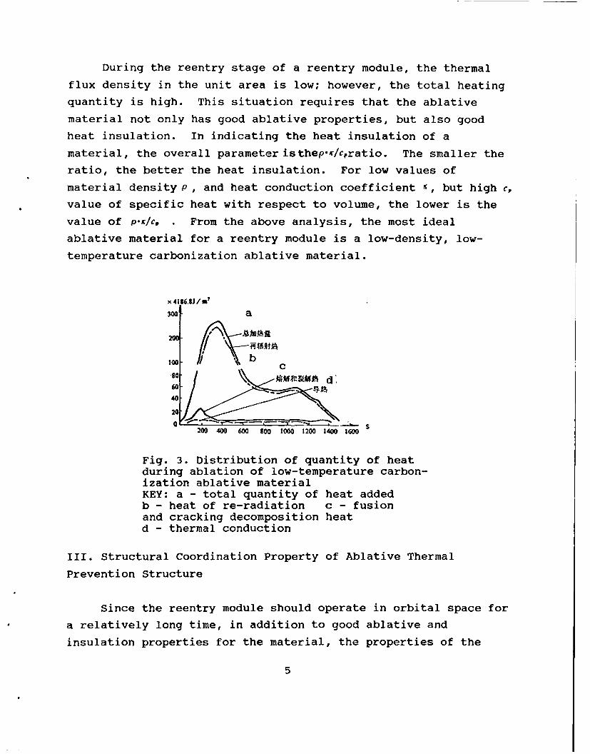
During the reentry stage of a reentry module, the thermal
flux density in the unit area is low; however, the total heating
quantity is high. This situation requires that the ablative
material not only has good ablative properties, but also good
heat insulation. In indicating the heat insulation of a
material, the overall parameter isthepK/cratio. The smaller the
ratio, the better the heat insulation. For low values of
material density P, and heat conduction coefficient K, but high c,
value of specific heat with respect to volume, the lower is the
value of p.4/c, . From the above analysis, the most ideal
ablative material for a reentry module is a low-density, low-
temperature carbonization ablative material.
x4196.S6/V
300 a
100 /
.go. Cd
60- ýA401
20"0 "|L
200 400 600 800 1000 1200 1400 1600
Fig. 3. Distribution of quantity of heatduring ablation of low-temperature carbon-ization ablative materialKEY: a - total quantity of heat addedb - heat of re-radiation c - fusionand cracking decomposition heatd - thermal conduction
III. Structural Coordination Property of Ablative Thermal
Prevention Structure
Since the reentry module should operate in orbital space for
a relatively long time, in addition to good ablative and
insulation properties for the material, the properties of the
5

material in space resisting vacuum radiation, coordination
between the material and the load-bearing structure, and the
formability of the material should also be considered.
In selecting a thermal prevention material for a reentry
module, the structural coordination property of the material is arelatively unique problem. Although some materials have very
good thermal properties, yet these materials have a relatively
greater difference between the coefficient of linear expansion of
the material, and the coefficient of linear expansion for the
load-bearing structure, therefore mismatching occurs during
heating and cooling.
1. Damage caused by structural incompatibility
Because of the structural incompatibility of the ablative
thermal-protection structure, the thermal-protection structure
may be damaged.
(1) In a cool environment, these damages include elongationdamage of the ablative layer, and compressive damage of the
ablative layer.
(2) the compression damage of the ablative layer during the
reentry process; and
(3) in a cool environment, elongation damage of the adhesive
layer, or shearing damage along the margins.
In the general situation, strength of the resin composite
material is lower than the strength of metal materials. In
particular, Lhe tensile strength of plastics is relatively low.When the reentry module is in the low-temperature environment
during the orbital stage, since the linear expansion of the
ablative layer and of the structure layer are not compatible
(generally, the coefficient of linear expansion is greater thanthat of metals), the ablative layer is in the elongation state as
the layer is compressed along the structure; therefore, theelongation damage of the ablative layer at low temperatures is
6

relatively significant.
2. Measures to solve the problem of structural
incompatibility
There are three technical approaches in solving the problem
of compatibility between the ablative material layer and the
structure.
(1) Select an ablative material such that its linear
expansion coefficient is close to the coefficient of the
structure; or, select such an ablative material with better
elasticity, thus reducing the stresses caused by expansion
incompatiblity.
(2) Improve the connection mode between the ablative thermal
protection layer and the structure layer, or modify the
structural form of the thermal protection system.
(3) Select such an adhesive with better flexibility between
the ablative layer and the structure layer; thus, the adhesive
layer has sufficient elasticity and strength over a wider
temperature range. The strains caused by different thermal
expansion between the structure and the ablative thermal
protection layer can be adjusted. This compression flexible
adhesion system can absorb large amounts of energy due to
shearing, compression and tension deformations, thus harmonizing
the incompatibility between thermal expansion of the ablative
thermal protection layer and the structure layer.
IV. Thermal Analysis of Ablative Thermal Protection Structure
[3,7,8]
When selecting the thermal protection scheme and design of
thermal protection structure, a thermal analysis of the ablative
thermal protection structure should be conducted based on the
thermal environment, thus determining the thickness of the
ablative material, ablative layer and the heat insulation layer;
thickness of the heat insulation layer; the working temperatures
7

of the adhesive layer and the load-bearing structure; and the
temperature distribution of various sites along the depth
direction of the various layers.
1. Thermal design criterion of ablative thermal protection
layer
The thickness of the ablative thermal protection layer is
determined by the following factors.(1) Design conditions should be selected for the ballistic
external heat flow during heating with the maximum total heating
that may occur in the reentry corridor.
(2) The allowable working temperature at the adhesive layer
between the ablative thermal protection layer and the thermal
insulation layer or the layer of load-bearing structure is an
important factor.
(3) the allowable working temperature of materials for the
load-bearing structure;
(4) If the equal-thickness design in the module is applied,
it is required to select the site with the largest thermal load
as the cross section for thermal analysis. If the variable
thickness design is adopted in the entire module, various sites
with typical representation should be selected for the thermal
analysis.
2. Comparative selection of ablative computation model
With external thermal flux heating, three regions are formed
in the low-temperature carbonization ablative material:
carbonization region, reaction region (decomposition region) and
the original material layer, referring to Fig. 4 (a).
The thermal •onductivity and material tranisport equations
are derived, based on the properties of these three regions. The
thermal analysis computations can be conducted with known
boundary conditions and known initial conditions. To simplify
the computation, the compression in the reaction region can be
8

compressed into a plane; this is shown in Fig. 4 (b) as the
ablation model.
21
S3"-
4 4
(a) (b)
Fig. 4. Models for two types of ablationcomputationKEY: 1 - carbon layer 2 - reaction region3 - original material 4 - structure5 - decomposition surface
The thermal analysis is conducted on two ablation models for
the thermal prevention structure of the reentry module.
Moreover, the computation results are compared with the results
from ground experiments and flight experiments. Between the
computation results and the experimental results for two types of
ablation models, these results are basically consistent. The
computation results and the experimental results by using the
ablative model in Fig. 4 (a) are relatively consistent with the
temperature distribution of the carbon layer thickness, and along
the depth direction of the ablation thermal prevention structure.
By applying the ablation model in Fig. 4 (b), the computed
thickness of carbon layer is on the thicker side as compared with
the experimental value; the computed surface temperature is on
the lower side; and the computed temperature at the back wall is
on the higher side.
9

The computation model in Fig. 4 (a) should be employed in
the thermal analysis and design computation of the ablative
thermal protection structure of the reentry module. If the
computation in Fig. 4 (b) is applied in the design, the
comiputation will ailow the design to be on the conservative side;
however, the model can be used for reaching a general estimate.
V. Results
The ablative thermal protection structure is the kind of
thermal protection structure that is employed fairly broadly in
the thermal protection of reentry vehicles. This structure is
most often applied in reentry modules and reentry vehicles of
reentry-type satellites. The structure can be used only once.
The ablative thermal protection structure has higher
adaptation capability for variations in external thermal flux.
This is because the ablative material is insensitive to
variations of thermal flux density; damage to the thermal
prevention structure will not caused due to variation of local or
instantaneous thermal flux density. Conversely, the thermal
efficiency of the thermal protection structure will increase with
increasing density of thermal flux (within certain range).
Therefore, this is a thermal protection structure with relatively
high reliability.
When designing the ablative thermal protection structure,
adequate cc-sideration should be given to thermal compatibility
between the thermal protection layer and the structural layer
under the alternating environments of high and low temperatures
in the operating orbit.
When selecting materials, further adequate consideration
should be given to capabilities of resisting vacuum, radiation
and low-temperature soaking of the ablative material. Finally,
10

the realistic feasibility in the technical process is the
determining factor in deciding on the thermal protection
structure.
The article was received for publication on 30 August 1990.
REFERENCES
1. Bryan, Erb R., Greenshields, D. H., Chauvin, L. T., andPavlosky, J. E., "Apollo Thermal Protection SystemDevelopment," AIAA, paper No. 68-1142.
2. Pavlosky, J. E., and Leslie, G. St. Leger, "Apollo ExperienceReport--Thermal Protection Subsystem," NASA, TND-7564,1974.
3. Mecown, James W., "Review of Structural and Heat ShieldConcepts for Future Reentry," AIAA, Paper No. 68-1127, 1968.
4. Kotanchik, J. M., "Manned Spacecraft Materials Problems,"Astronautics/Aeronautics, 1964, 2 (7): pp 12-17.
5. Vaughan, W. L., "Elastomeric Adhesive for AerospaceApplications," Seventh Annual Sample National SymposiumTransaction, 9-1-9-26, 1964.
6. Kuno, James K., "Comparison of Adhesive Classes for StructuralBonding at Ultrahigh and Cryogenic Temperature Extremes,"Seventh Annual Sample National Symposium Transaction, 12-1,1964.
7. Curry D. M., "An Analysis of a Charring Ablation ThermalProtection System," NASA, TND-3150, 1965.
8. Swann, Robert T., and Pittmen, Cland M., "Numerical Analysisof the Transient Response of Advanced Thermal ProtectionSystems for Atmospheric Entry," NASA, TND-1370, 1962.
II