Chemically Reactive Working Fluids for the Capture and ... · Chemically Reactive Working Fluids...
19
Chemically Reactive Working Fluids for the Capture and Transport of Concentrated Solar Thermal Energy for Power Generation SunShot CSP Program Review 2013 Argonne National Laboratory Program Start Date: October 1, 2012 R. Brotzman (PI), M. Urgun-Demirtas, J. Libera
Transcript of Chemically Reactive Working Fluids for the Capture and ... · Chemically Reactive Working Fluids...
Chemically Reactive Working Fluids for the Capture and Transport of Concentrated Solar
Thermal Energy for Power Generation
SunShot CSP Program Review 2013 Argonne National Laboratory Program Start Date: October 1, 2012
R. Brotzman (PI), M. Urgun-Demirtas, J. Libera
Presentation Outline
Project Description Project Objectives and Goals Project Innovation Compared With Baseline Key Technical Results, Analysis, and Accomplishments to Date
– CRWF candidates – CSP process simulations on CRWF candidates – Reaction test system (RTS)
Conclusions
SunShot CSP Program Review 2013, Phoenix, AZ April 23-25, 2013
Project Description
Project addresses cost barrier of power produced by CSP plants Specifically, the primary heat transfer fluid (HTF), which transmits the collected
solar power to power cycle Evaluate Chemically Reacting Working Fluids (CRWFs) as HTFs in the range of
650°C–1200°C – sensible, latent, and chemical reaction heat Work plan
– Conduct thermodynamic and process simulations using Aspen Plus® – use simulations and published kinetic data to identify CRFW candidates and process window to enable reversible reactions in the temperature ranges of 650°C–1200°C
– Design CRWF cycling experiments to demonstrate thermal capture, transport, and release between 650°C and 1200°C, below 160-bar
– Test CRWF system to validate the models and to demonstrate that more than double the power output efficiency of current CSP systems is achievable, scalable, and robust
SunShot CSP Program Review 2013, Phoenix, AZ April 23-25, 2013
Project Objectives and Goals
Demonstrate lab-scale feasibility of employing CRWFs as HTFs for CSP systems Program Goals
– Identify CRFW candidates and process window to enable reversible reactions in the temperature ranges of 650°C–1200°C
– Compare CRWF cycling experimental data with commercial HTF’s DOWTHERM A® and Solar Salt
– Compare CRWF cycling experimental data to systems that use air as the working fluid and to the models of super critical CO2 as a working fluid
– Determine CRWF compatibility with CSP system components, material availability, cost competitiveness, safety, environmental impact, and the need for catalysts
– Develop predictive models to determine power production and efficiency given various designs, and process parameters
– CRWF system will be tested to validate the models and to demonstrate that more than double the power output efficiency of current CSP systems is achievable, scalable, and robust
SunShot CSP Program Review 2013, Phoenix, AZ April 23-25, 2013
Project Innovation Compared With Baseline
State-of-the-art CSP has a maximum solar-to-electric efficiency of 29.4% * Operationally, industrial-scale plants are < 15% efficient – primary HTFs absorb
solar heat as sensible heat at near atmospheric pressure in solar collector and are pumped through heat exchangers to transfer heat to water to produce steam for power generation
Innovation: Chemically reacting fluids (CRWFs) as HTFs – Sensible, latent, and chemical reaction heat of a reversibly reacting fluid – Sun’s energy absorbed by endothermic decomposition of CRWF at high temperature – At lower temperature, exothermic regeneration of decomposition state releases heat
absorbed at higher temperature – Enable substantially more heat/mass to be captured in the range of 650°C–1200°C – CRWF is cycled reversibly between different chemical states, dictated by chemical
equilibrium, and coupled to standard steam cycle
* Washom, B., Paper No. 849516, Proceeding of the IECEC, San Francisco, CA (1984)
SunShot CSP Program Review 2013, Phoenix, AZ April 23-25, 2013
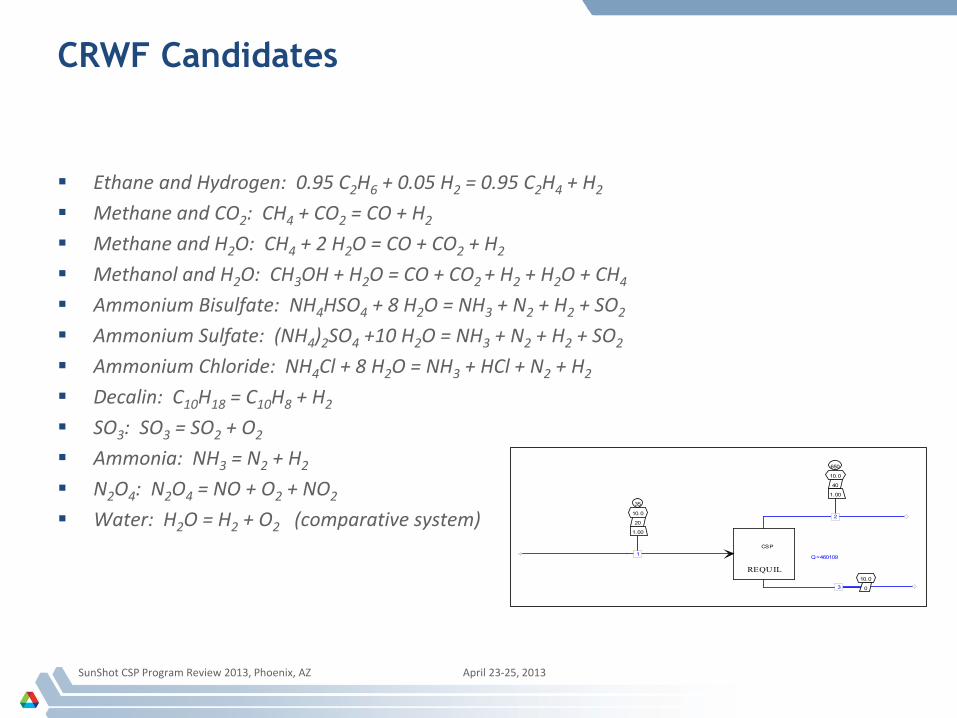
CRWF Candidates
Ethane and Hydrogen: 0.95 C2H6 + 0.05 H2 = 0.95 C2H4 + H2 Methane and CO2: CH4 + CO2 = CO + H2 Methane and H2O: CH4 + 2 H2O = CO + CO2 + H2 Methanol and H2O: CH3OH + H2O = CO + CO2 + H2 + H2O + CH4 Ammonium Bisulfate: NH4HSO4 + 8 H2O = NH3 + N2 + H2 + SO2 Ammonium Sulfate: (NH4)2SO4 +10 H2O = NH3 + N2 + H2 + SO2 Ammonium Chloride: NH4Cl + 8 H2O = NH3 + HCl + N2 + H2 Decalin: C10H18 = C10H8 + H2 SO3: SO3 = SO2 + O2 Ammonia: NH3 = N2 + H2 N2O4: N2O4 = NO + O2 + NO2 Water: H2O = H2 + O2 (comparative system)
SunShot CSP Program Review 2013, Phoenix, AZ April 23-25, 2013
REQUIL
CSP
Q=460109
35
10.0
20
1.00
1
650
10.0
40
1.00
2
10.0
03
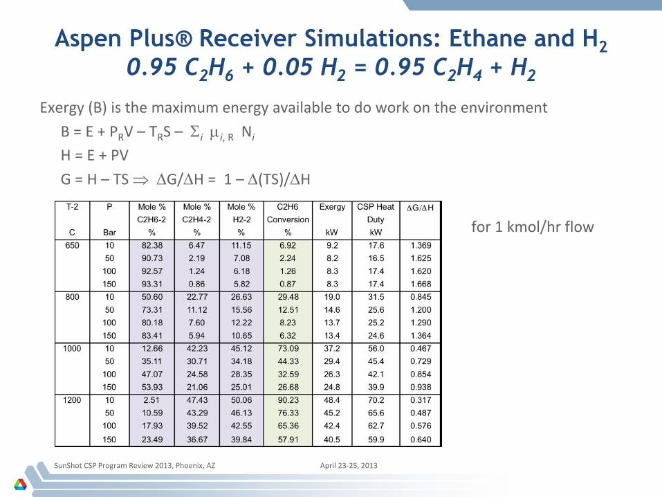
Aspen Plus® Receiver Simulations: Ethane and H2 0.95 C2H6 + 0.05 H2 = 0.95 C2H4 + H2
Exergy (B) is the maximum energy available to do work on the environment B = E + PRV – TRS – Σi µi, R Ni
H = E + PV G = H – TS ⇒ ∆G/∆H = 1 – ∆(TS)/∆H for 1 kmol/hr flow
SunShot CSP Program Review 2013, Phoenix, AZ April 23-25, 2013
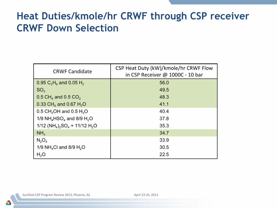
Heat Duties/kmole/hr CRWF through CSP receiver CRWF Down Selection
SunShot CSP Program Review 2013, Phoenix, AZ April 23-25, 2013
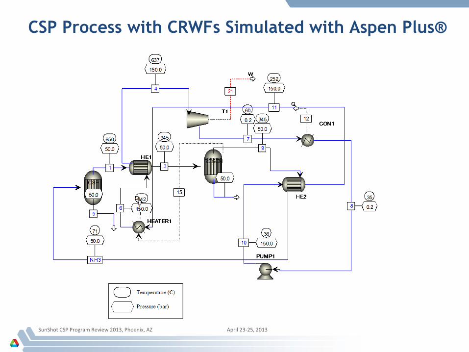
CSP Process with CRWFs Simulated with Aspen Plus®
SunShot CSP Program Review 2013, Phoenix, AZ April 23-25, 2013
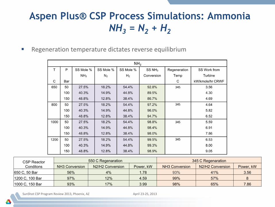
Aspen Plus® CSP Process Simulations: Ammonia NH3 = N2 + H2
SunShot CSP Program Review 2013, Phoenix, AZ April 23-25, 2013
CSP Reactor Conditons
550 C Regenaration 345 C Regenaration NH3 Conversion N2/H2 Conversion Power, kW NH3 Conversion N2/H2 Conversion Power, kW
650 C, 50 Bar 56% 4% 1.78 93% 41% 3.56 1200 C, 100 Bar 97% 12% 4.59 99% 57% 8 1000 C, 150 Bar 93% 17% 3.99 98% 65% 7.86
Regeneration temperature dictates reverse equilibrium
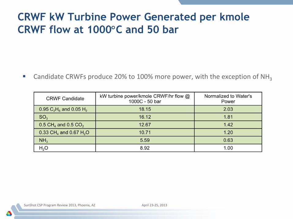
CRWF kW Turbine Power Generated per kmole CRWF flow at 1000°C and 50 bar
SunShot CSP Program Review 2013, Phoenix, AZ April 23-25, 2013
Candidate CRWFs produce 20% to 100% more power, with the exception of NH3
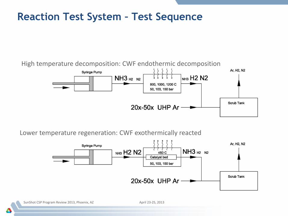
Reaction Test System – Test Sequence
SunShot CSP Program Review 2013, Phoenix, AZ April 23-25, 2013
High temperature decomposition: CWF endothermic decomposition Lower temperature regeneration: CWF exothermically reacted
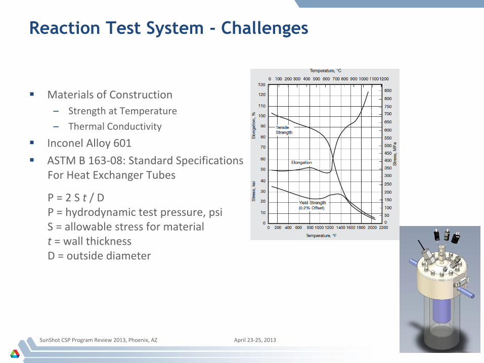
Reaction Test System - Challenges
SunShot CSP Program Review 2013, Phoenix, AZ April 23-25, 2013
Materials of Construction – Strength at Temperature – Thermal Conductivity
Inconel Alloy 601 ASTM B 163-08: Standard Specifications
For Heat Exchanger Tubes
P = 2 S t / D P = hydrodynamic test pressure, psi S = allowable stress for material t = wall thickness D = outside diameter
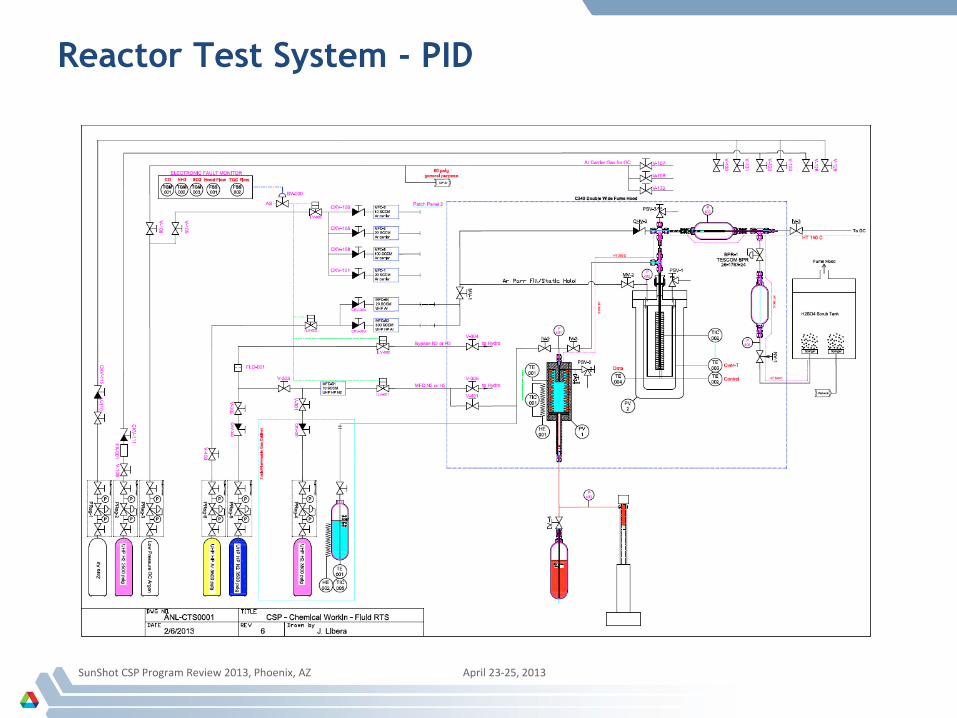
Reactor Test System - PID
SunShot CSP Program Review 2013, Phoenix, AZ April 23-25, 2013
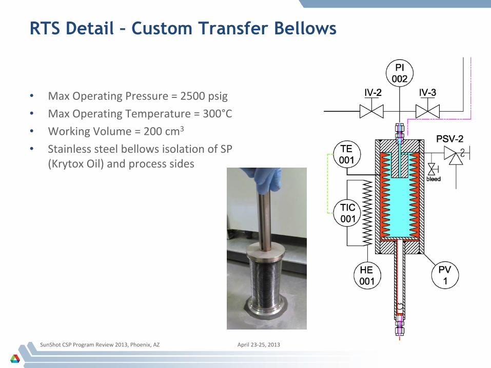
RTS Detail – Custom Transfer Bellows
• Max Operating Pressure = 2500 psig • Max Operating Temperature = 300°C • Working Volume = 200 cm3
• Stainless steel bellows isolation of SP (Krytox Oil) and process sides
SunShot CSP Program Review 2013, Phoenix, AZ April 23-25, 2013
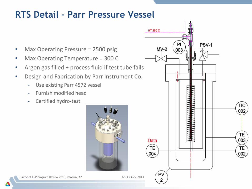
RTS Detail – Parr Pressure Vessel
• Max Operating Pressure = 2500 psig • Max Operating Temperature = 300 C • Argon gas filled + process fluid if test tube fails • Design and Fabrication by Parr Instrument Co.
- Use existing Parr 4572 vessel - Furnish modified head - Certified hydro-test
SunShot CSP Program Review 2013, Phoenix, AZ April 23-25, 2013
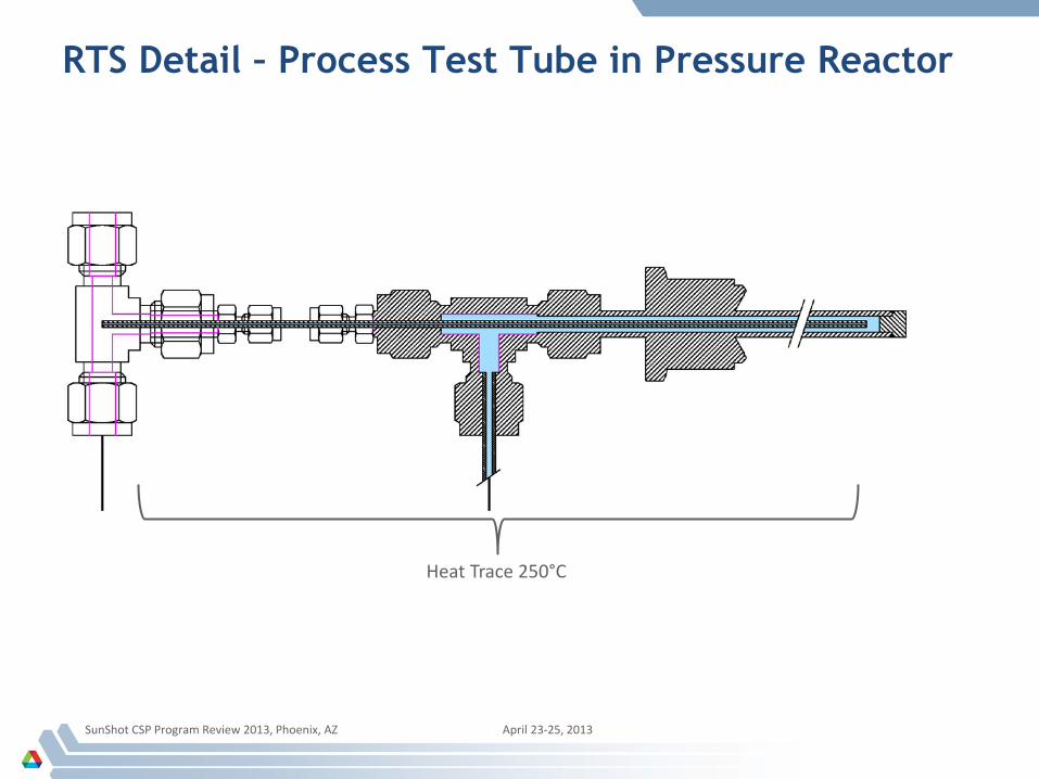
RTS Detail – Process Test Tube in Pressure Reactor
SunShot CSP Program Review 2013, Phoenix, AZ April 23-25, 2013
Heat Trace 250°C
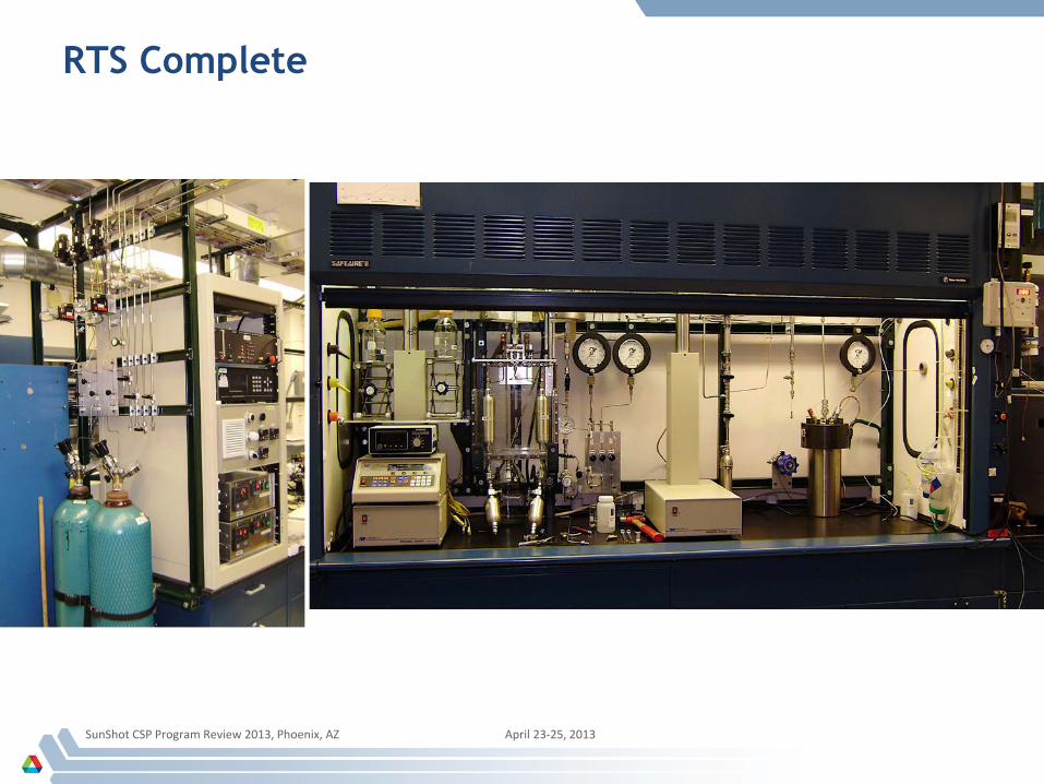
RTS Complete
SunShot CSP Program Review 2013, Phoenix, AZ April 23-25, 2013
CRWF Conclusions
Future work planned – Experimentally validate CRWF systems at 650°C to 1200°C and 25-bar to 150-bar – Determine need for catalyst – Conduct postmortem evaluation of reactor materials
Impact of work – Demonstrate feasibility of CRWFs as HTFs for CSP systems at lab-scale – Demonstrate that more than double the power output efficiency of current CSP systems
is achievable, scalable, and robust
Breakthroughs – Quantify process and metrics, including regeneration conditions, to maximize power
output
SunShot CSP Program Review 2013, Phoenix, AZ April 23-25, 2013