
Chemical kinetics and dynamics of plasma-assisted ... · Chemical kinetics and dynamics of...
22
Chemical kinetics and dynamics of plasma-assisted pyrolysis of assorted non-nuclear waste Dr B V Babu Professor of Chemical Engineering & Dean – Educational Hardware Division (EHD) Birla Institute of Technology and Science (BITS) PILANI – 333 031 (Rajasthan) India Phone: 01596-245073 Ext 259/212 Fax: 01596-244183 E-mail: [email protected] ; [email protected] Homepage: http://discovery.bits-pilani.ac.in/discipline/chemical/BVb 1. Introduction Waste management is an important issue in both developed and developing countries nowadays. Today’s society uses, and quickly discards, a large volume of an increasingly diverse range of polymeric materials. Organic wastes, such as used rubber and plastic are among the waste materials that represent problematic wastes on one hand and valuable potential as secondary raw materials on the other hand (Huang and Tang, 2007). Most conventional chemical methods cannot deal with Municipal Solid Waste (MSW) due to the diversity of its composition, which range from simple thermoplastics to complex thermosets and composites (Guddeti et al., 2000). Nowadays MSW also contains outdated computer parts and electronic items. Printed Circuit Boards (PCB) are a major part of the waste from electrical and electronic equipment (WEEE); utilization, recycling, and final disposal of these products have become important issues (Hung-Lung et al., 2007). Apart from the municipal solid waste, biomass generated from various agriculture residues (majority coming from rice and wheat straw, corn stalk, cotton stems and bagasse) are wastes, which are used as primary sources of energy for domestic purposes by low-efficiency methods of direct combustion (Shuangning et al., 2006). Biomass is often regarded as a renewable, storable and transportable energy source; it is available in various forms such as wood, agricultural and forest residues, and garbage. Biomass energy is neutral with respect to CO 2 emission, and can significantly alleviate the greenhouse effect caused by fossil fuel consumption (Tang and Huang, 2005). To alleviate part of our energy crisis and environmental degradation, it has become imperative to make use of appropriate technologies for recovery of resources from non- conventional sources like MSW and biomass residues. Pyrolysis and gasification are efficient ways for biomass utilization. However, the gas yield from conventional pyrolysis technology is normally below 40 wt% of biomass feed and the accompanying corrosion to the equipments caused by the high content of tar vapor contained in the gas
Transcript of Chemical kinetics and dynamics of plasma-assisted ... · Chemical kinetics and dynamics of...

Chemical kinetics and dynamics of plasma-assisted
pyrolysis of assorted non-nuclear waste
Dr B V Babu
Professor of Chemical Engineering &
Dean – Educational Hardware Division (EHD)
Birla Institute of Technology and Science (BITS)
PILANI – 333 031 (Rajasthan) India
Phone: 01596-245073 Ext 259/212
Fax: 01596-244183
E-mail: [email protected]; [email protected]
Homepage: http://discovery.bits-pilani.ac.in/discipline/chemical/BVb
1. Introduction
Waste management is an important issue in both developed and developing countries
nowadays. Today’s society uses, and quickly discards, a large volume of an increasingly
diverse range of polymeric materials. Organic wastes, such as used rubber and plastic are
among the waste materials that represent problematic wastes on one hand and valuable
potential as secondary raw materials on the other hand (Huang and Tang, 2007). Most
conventional chemical methods cannot deal with Municipal Solid Waste (MSW) due to
the diversity of its composition, which range from simple thermoplastics to complex
thermosets and composites (Guddeti et al., 2000). Nowadays MSW also contains
outdated computer parts and electronic items. Printed Circuit Boards (PCB) are a major
part of the waste from electrical and electronic equipment (WEEE); utilization, recycling,
and final disposal of these products have become important issues (Hung-Lung et al.,
2007).
Apart from the municipal solid waste, biomass generated from various agriculture
residues (majority coming from rice and wheat straw, corn stalk, cotton stems and
bagasse) are wastes, which are used as primary sources of energy for domestic purposes
by low-efficiency methods of direct combustion (Shuangning et al., 2006). Biomass is
often regarded as a renewable, storable and transportable energy source; it is available in
various forms such as wood, agricultural and forest residues, and garbage. Biomass
energy is neutral with respect to CO2 emission, and can significantly alleviate the
greenhouse effect caused by fossil fuel consumption (Tang and Huang, 2005).
To alleviate part of our energy crisis and environmental degradation, it has become
imperative to make use of appropriate technologies for recovery of resources from non-
conventional sources like MSW and biomass residues. Pyrolysis and gasification are
efficient ways for biomass utilization. However, the gas yield from conventional
pyrolysis technology is normally below 40 wt% of biomass feed and the accompanying
corrosion to the equipments caused by the high content of tar vapor contained in the gas
phase is serious (Tang et al., 2003). These problems are difficult to overcome due to only
limited control of the product composition in pyrolysis and gasification processes.
Incineration of organic waste may utilize the energy content of organic waste but is
associated with the generation of SO2, NOx and other hazardous emissions (Huang and
Tang, 2007).
Thermal plasma technology has been under active development for a long time. The
technology is now well established in metallurgical processing, materials synthesis etc.
The extremely high temperatures generated by plasma torches have spurred development
of their application to waste processing, as they are capable of significantly decreasing
the waste volume to a non-leachable residue. By far the most important application of
thermal plasma waste treatment is focused on the destruction of hazardous wastes rather
than recycling because of economic issues. Nevertheless, in recent years, the interest in
energy and resource recovery from waste has grown significantly, and substantial
research studies on the use of plasmas in organic waste treatment have been reported in
the literature (Huang and Tang, 2007).
Pyrolysis has the potential of transforming solid wastes into useful recyclable products,
but conventionally leads to a wide spectrum of pyrolysis products, which are difficult to
be separated and utilized. Recently, attention has been paid to plasma-assisted pyrolysis
and plasma gasification. Guddeti et al. (2000) used an inductively coupled plasma
technology for the depolymerization of the polyethylene. Huang et al (2003) used waste
rubber as the raw material for production of syngas (CO2 and H2) by thermal plasma
pyrolysis, and the combustible heat value of the produced gas was 5-9 MJ/m3. Tang and
Huang (2005) developed a laboratory-scale capacitively coupled radio frequency (RF)
plasma pyrolysis reactor for wood and char gasification. Shuangning et al. (2006)
developed a plasma heated laminar entrained flow reactor in order to study the
volatilization characteristics of biomass particles at flash heating rates. Corn stalk and
wheat straw is used as a raw material. And very recently plasma pyrolysis method is
employed to recycle the metals and brominated compounds blended into printed circuit
boards (Hung-Lung et al., 2007).
Plasma pyrolysis has a number of unique advantages over conventional pyrolysis. It
provides high temperature and high energy for reaction. The reaction sample is heated up
to a high temperature rapidly, and some reactions occur that do not appear in
conventional pyrolysis. It is an appropriate method for polymer pyrolysis. It also
produces a gas with low tar content and high heating value, which can be applied well to
gas turbines for power generation or used as a synthesis gas for hydrogen production
(Tang and Huang, 2005). There is a tremendous scope for applying plasma assisted
pyrolysis of assorted non-nuclear waste such as biomass, printed circuit boards, organic
waste, medical waste etc., for obtaining useful energy.
2. Plasma Properties
Plasma is considered by many to be the fourth state of matter, following the more
familiar states of solid, liquid and gas. A gas converts into the plasma upon addition of

high energy. In other words, plasma is an ionized gas resulting from an electrical
discharge (Huang and Tang, 2007). Gases will not conduct electricity under normal
conditions, but when a very high voltage is applied the insulating properties begin to
break down. As electricity starts to flow through the gas it heats up and it begins to
conduct more and hot plasma is formed. Well-known examples of plasmas are the sun
and the lightning. However, these are examples of natural and uncontrolled plasmas. Man
made controlled plasmas have been used in industry for many years and for a number of
diverse applications, such as chemical analysis and the cutting of metals (David and
Peter, 2007).
Plasma, the state of matter formed by removing the bound electrons from atoms, is an
electrically conducting fluid consisting of charged and neutral particles. The charged
particles have high kinetic energies. When the ionized species in the plasma, recombine
with the stripped electrons, significant amounts of energy in the form of ultraviolet
radiation are released. The particle kinetic energy takes the form of heat and can be used
for decomposing chemicals. In addition, the presence of charged and excited particles
renders the plasma environment highly reactive, which can catalyze homogeneous and
heterogeneous chemical reactions (Nema and Prasad, 2002).
There are mainly two types of laboratory plasma exist: (1) high temperature or fusion
plasmas, and (2) low temperature or gas discharges. High temperature plasma implies
that all species (electrons, ions and neutral species) are in a thermal equilibrium state.
Low temperature plasma is divided into thermal plasma, also called quasi-equilibrium
plasma, which is in a local thermal equilibrium (LTE) state, and non-thermal plasma, also
called non-equilibrium plasma or cold plasma. The state parameters of each type of
plasma are listed in Table – 1 (Huang and Tang, 2007).
Table-1. Classification of Plasmas
Plasma State Example
High temperature plasma (Equilibrium Plasma)
Te = Ti = Th, Tp = 106 K – 10
8 K
ne ≥ 1020
m-3
Laser fusion plasma
Low Temperature Plasma
Thermal Plasma
(Quasi-equilibrium plasma)
Te ≈ Ti ≈ Th, Tp = 2 x10³ K – 3 x 10
4 K
ne ≥ 1020
m-3
Arc Plasma, atmospheric RF
discharge
Non-thermal plasma
(Non-equilibrium plasma)
Te ≥ Th ≈ 3 x10² K – 4 x 10
2 K
ne ≈1010
m-3
Corona discharge
Te = electron temperature; Ti = ion temperature; Th = Neutral temperature; Tp = Plasma temperature; ne =
Electron density
3. Plasma Generators
Thermal plasma generation can be achieved using a direct current (DC) or an alternating
current (AC) electrical discharge or using a radio frequency (RF) induction or a
microwave (MW) discharge. A DC arc discharge provides a high energy density and high
temperature region between two electrodes. RF plasma torches utilize inductive or
capacitive coupling to transfer electromagnetic energy from the RF power source to the
plasma working gas.

3.1 DC Arc Plasma Generator
The DC arc plasma generator consists of a water-cooled tungsten tip with an auxiliary
copper anode surrounding it. The water-cooled anode cup is placed in front of the
cathode. Both anode and cathode are surrounded by a magnetic field coil, which
produces an axial magnetic field parallel to both the anode and cathode axes. The whole
torch assembly is mounted on a flange of around 100 mm diameter in a side port. The arc
is initiated between the cathode and the auxiliary anode, and then transferred to the
copper anode (Nema and Prasad, 2002).
DC arc plasma melting and waste treatment systems are generally implemented as batch
processes due to their relatively short electrode lifetimes. The average lifetime of the
electrodes ranges between 200 and 500 h of operation under oxidative conditions.
Product contamination can also occur due to electrode erosion. This has prevented
conventional DC torches with refractory metal (tungsten) cathodes from being widely
used for the transferred-arc melting of reactive metals such as Ti (Guddeti et al., 2000).
Temperature in the core of the plasma plume can be greater than 30000 K, whereas in the
marginal zones, the temperature decreases rapidly and the average operating temperature
can be as high as 5000 K (Huang and Tang, 2007). Arc torches and electrodes are usually
water cooled to maintain temperature. DC torch systems may prone to ‘stray-arcing’
which has reportedly led to sufficient leakage of torch cooling water into the furnace to
warrant replacement of the dc torch by a simpler hollow graphite electrode (Guddeti et
al., 2000).
In the presence of a sufficiently high gas flow; the plasma extends beyond one of the
electrodes in the form of a plasma jet. The design of transferred and nontransferred arc
DC torches does not favor the injection of feedstock materials directly into or through the
plasma region. Excessive loading of constricted plasma jets can lead to physical and
electrical instabilities in the arc and even arc extinction. Several novel center-feed
hollow- or multicathode DC torches have been developed for plasma spray coating
applications. These designs have not yet been scaled up to the power levels required for
processing waste and the ability to feed large amounts of material through the cathode(s)
without affecting the stability of the arc is questionable (Guddeti et al., 2000).
A special new-type plasma torch with a DC electric arc stabilized by a combination of
argon flow and water vortex is developed by Van Oost et al. (2006). The DC argon–
water stabilized torch with W–Th cathode generates an O–H–Ar plasma with extremely
high enthalpy and temperature. The anode of the torch is a rotating water-cooled copper
disc, which is positioned outside the arc chamber downstream of the torch exit nozzle.
Additional argon was supplied into the anode chamber to protect the anode against the
flow of reaction gases. The hybrid gas–water stabilization provides the possibility of
controlling the parameters of the plasma jet and the plasma composition in a wide range
from high enthalpy, low-density plasmas typical for water-stabilized torches to lower
enthalpy, higher-density plasmas generated in gas-stabilized torches. Both the high
temperature and the composition of plasma generated in argon/water torches are highly

advantageous for the waste treatment process. The other characteristic feature of this
hybrid torch is the very low mass-flow rate of plasma. As low amount of plasma carries
high energy, the power needed for heating of plasma to reaction temperature is very low,
and the efficiency of utilizing plasma power for waste destruction is extremely high. The
torches with water stabilization have been utilized at industrial scale for plasma spraying.
Due to the physical characteristics of generated plasma the spraying rates and powder
throughputs achieved with these torches are several times higher than for classical gas-
stabilized torches (Van Oost et al., 2006)
3.2 RF Plasma Generator
RF plasma generators are very compact and deliver extraordinarily high input energy per
unit volume. Unlike DC arc plasma torches, there are no locally high temperature arcs,
no moving parts and no parts subject to wear. RF current and microwaves can be
transferred through insulators, so the use of external electrodes is possible. In this way,
the electrodes are not exposed to the severe conditions of thermal plasmas and, therefore,
have a very long lifetime. RF plasma generators are commonly available at power levels
of 100 kW. RF plasma generates a very diffuse plume, and the design of external
electrodes favors the injection of feedstock material directly into or through the plasma
region. In RF plasma jet, the temperature at the central channel reaches up to 6000 K.
Table – 2 shows the typical comparison of the DC arc and RF plasma generator (Huang
and Tang, 2007).
Table-2. Comparison of DC arc and RF plasma generator (Huang and Tang, 2007)
Item DC Arc Plasma RF Plasma
Temperature 5000 – 10000 K 3000 – 8000 K
Electrode erosion Yes (1000- 3000 h lifetime in inert
gas and 200 -500 h in oxidative
conditions)
No
Cooling of plasma generator and
reactor
Required Required
Plasma ignition Easy Difficult
Plasma volume Small Medium
Gas velocity High High
Solid feeding position Downstream of plasma Upstream of Plasma
Influence of solid feeding on plasma
stability
No Yes
Efficiency of power supply devices 60-90 % 40-70 %
A laboratory-scale capacitively coupled radio frequency (RF) plasma pyrolysis reactor
working in reduced pressure has been developed by Tang and Huang (2005). RF
capacitively coupled plasma process is operated at low pressure (approximately 3000–
8000 Pa abs) and a moderate gas temperature suitable for biomass pyrolysis. The high
efficiency of plasma pyrolysis and the high efficiency of energy utilization are combined
in their experimental design (Tang and Huang, 2005). Experiments have been performed
to examine the characteristics of this RF plasma reactor and the products of biomass
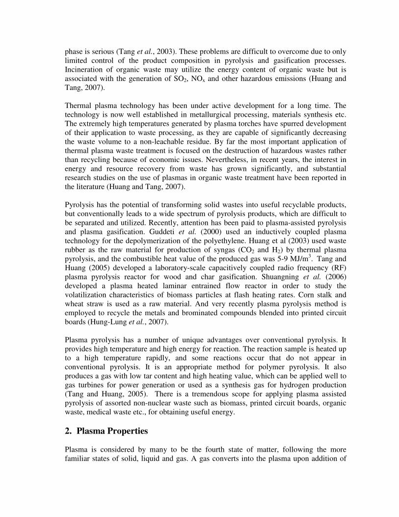
gasification. Typical experimental setup of the capacitively coupled radio frequency (RF)
plasma pyrolysis apparatus is shown in Fig. 1. It consists of a radio frequency plasma
source with power output 0–2000 W and a matching network. The pyrolysis reactor is a
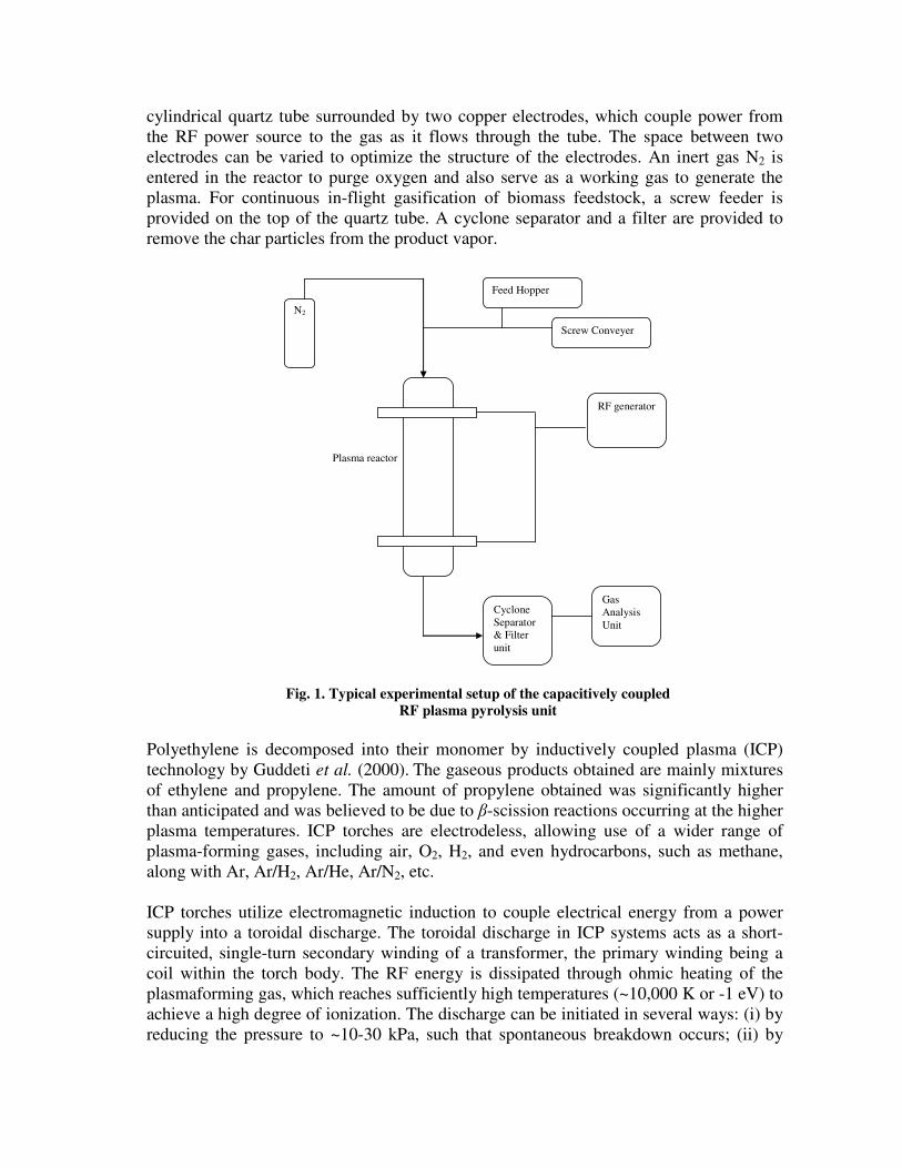
cylindrical quartz tube surrounded by two copper electrodes, which couple power from
the RF power source to the gas as it flows through the tube. The space between two
electrodes can be varied to optimize the structure of the electrodes. An inert gas N2 is
entered in the reactor to purge oxygen and also serve as a working gas to generate the
plasma. For continuous in-flight gasification of biomass feedstock, a screw feeder is
provided on the top of the quartz tube. A cyclone separator and a filter are provided to
remove the char particles from the product vapor.
N2
RF generator
Feed Hopper
Screw Conveyer
Plasma reactor
Cyclone
Separator
& Filter
unit
Gas
Analysis
Unit
Fig. 1. Typical experimental setup of the capacitively coupled
RF plasma pyrolysis unit
Polyethylene is decomposed into their monomer by inductively coupled plasma (ICP)
technology by Guddeti et al. (2000). The gaseous products obtained are mainly mixtures
of ethylene and propylene. The amount of propylene obtained was significantly higher
than anticipated and was believed to be due to β-scission reactions occurring at the higher
plasma temperatures. ICP torches are electrodeless, allowing use of a wider range of
plasma-forming gases, including air, O2, H2, and even hydrocarbons, such as methane,
along with Ar, Ar/H2, Ar/He, Ar/N2, etc.
ICP torches utilize electromagnetic induction to couple electrical energy from a power
supply into a toroidal discharge. The toroidal discharge in ICP systems acts as a short-
circuited, single-turn secondary winding of a transformer, the primary winding being a
coil within the torch body. The RF energy is dissipated through ohmic heating of the
plasmaforming gas, which reaches sufficiently high temperatures (~10,000 K or -1 eV) to
achieve a high degree of ionization. The discharge can be initiated in several ways: (i) by
reducing the pressure to ~10-30 kPa, such that spontaneous breakdown occurs; (ii) by

inserting an electrically conducting load, such as a graphite rod, into the torch to provide
a localized source of ionization through induction heating; or (iii) applying a high-voltage
Tesla coil to the central probe of the torch to generate a spark, which then ignites the
plasma (Stratton et al., 1999).
ICP torches can be more readily scaled up to the high power levels (>1 MW) required for
high-throughput commercial systems and their continuous operation is unaffected by the
electrode erosion and current carrying/cooling limitations of DC torches. ICP torch and
power supply efficiencies are, however, generally lower than those of DC plasma
systems. These are due primarily to the inherently lower energy-transfer efficiency of
induction heating and the lower efficiency of the high-frequency power supplies used.
High-frequency (MHz range) ICP systems often utilize vacuum tube-driven Class C-
tuned oscillators, which have inherent efficiencies of <50%, although more efficient solid
state power supplies operating at frequencies up to ~450 kHz are now being used in some
of the newer high-power ICP designs (Guddeti et al., 2000).
4. Pyrolysis
The thermochemical conversion of biomass (pyrolysis, gasification, combustion) is one
of the most promising non-nuclear forms of future energy. It is a renewable source of
energy and has many advantages from an ecological point of view (Babu and Chaurasia,
2003b). Pyrolysis is the thermochemical process that converts biomass into liquid (bio-oil
or bio crude), charcoal and noncondensable gases, acetic acid, acetone and methanol by
heating the biomass in the absence of air (Demirbas, 2001). The basic phenomena that
take place during pyrolysis are: (1) heat transfer from a heat source, leading to an
increase in temperature inside the fuel; (2) initiation of pyrolysis reactions due to this
increased temperature, leading to the release of volatiles and the formation of char; (3)
outflow of volatiles, resulting in heat transfer between the hot volatiles and cooler
unpyrolysed fuel; (4) condensation of some of the volatiles in the cooler parts of the fuel
to produce tar; and (5) autocatalytic secondary pyrolysis reactions due to these
interactions (Babu and Chaurasia, 2003a).
Pyrolysis can be used as an independent process for the production of useful energy
(fuels) and/or chemicals. Most biomass materials are chemically and physically
heterogeneous, and their components have different reactivities and yield different
products. The overall process of pyrolysis can be classified into primary and secondary
stages. When a solid particle of biomass is heated in an inert atmosphere the following
phenomena occur. Heat is first transferred to the particle surface by radiation and/or
convection and then to the inside of the particle. The temperature inside the particle
increases, causing (1) removal of moisture that is present in the biomass particle, (2) the
pre-pyrolysis and main pyrolysis reaction takes place. The heat changes due to the
chemical reactions, and phase changes contribute to a temperature gradient as a function
of time, which is nonlinear. Volatiles and gaseous products flow through the pores of the
particle and participate in the heat transfer process. The pyrolysis reactions proceed with
a rate depending upon the local temperature. During the pyrolysis process, the pores of
the solid are enlarged, and the solid particle merely becomes more porous because the

biomass converts into gases as discussed by Curtis and Miller (1999). According to
Anthony and Howard (1976), the enlarged pores of the pyrolyzing solid offer many
reaction sites to the volatile and gaseous products of pyrolysis and favor their interaction
with the hot solid. Inside the pyrolyzing particle, heat is transmitted by the following
mechanisms: (a) conduction inside the solid particle, (b) convection inside the particle
pores and (c) convection and radiation from the surface of the pellet (Babu and
Chaurasia, 2003b).
Depending on the operating conditions, the pyrolysis process can be divided into three
subclasses: conventional pyrolysis (carbonization), fast pyrolysis, and flash pyrolysis.
The ranges of the main operating parameters for pyrolysis processes are given in Table –
3. Conventional pyrolysis is defined as the pyrolysis that occurs under a slow heating
rate. This condition permits the production of solid, liquid, and gaseous pyrolysis
products in significant portions. If the aim is the production of mainly liquid and/or
gaseous products, a fast pyrolysis is recommended. The achievement of fast heating rates
requires high operating temperatures, very short contact times, and very fine particles.
Flash pyrolysis gives mostly gaseous products due to high heating rate and very small
particle size (Demirbas and Arin, 2002).
Table-3. Range of main operating parameters for pyrolysis processes
Parameters Conventional Pyrolysis Fast Pyrolysis Flash Pyrolysis
Pyrolysis Temperature (K) 550-950 850-1250 1050-1300
Heating rate (K/s) 0.1-1.0 10-200 >1000
Particle size (mm) 5-50 <1 <0.2
Solid residence time (s) 450-550 0.5 -10 <0.5
4.1 Kinetic Schemes of Pyrolysis
Different classes of mechanisms were proposed for the pyrolysis of wood and other
cellulosic materials (Di Blasi, 1993). The models are classified into three categories:
one-step global models; one-stage multi-reaction models; and two-stage semi-global
models. The first category of models considers pyrolysis as a single-step first order
reaction.
Parallel reactions:
Virgin biomass (Volatiles + Gases)1 (1)
Virgin biomass (Char)1 (2)
Secondary Interactions:
(Volatiles + Gases)1 + (Char)1 (Volatiles + Gases)2 + (Char)2 (3)
The second category of models discuss those mechanisms, which consider simultaneous
and competing first order reactions in which virgin wood decomposes into different
constitutes of pyrolysis products, namely, tar, char, and gases (Reactions (1) & (2)).
The third class of models considers pyrolysis to be a two-stage reaction, in which the
products of the first stage break up further in the presence of each other to produce
secondary pyrolysis products. Such models are presented for wood by Koufopanos et al.

(1991) [Reactions (1), (2) & (3)]. The scheme of reactions of Koufopanos’ models is
adapted by Jalan and Srivastava (1999), Srivastava et al. (1994; 1996) and Babu and
Chaurasia (2003a). Chan (1985) proposed a mechanism where volatiles and tar formed
by primary pyrolysis undergo secondary pyrolysis. The other primary reactions of
formation of char and gas from wood are parallel and competing with the tar formation
reaction. Babu and Chaurasia (2003a-c; 2004a-c) did extensive modeling and simulation
on pyrolysis. Kinetic Scheme proposed by Koufopanos et al. (1991) for the pyrolysis of
biomass based on the two-stage model is accepted and validated. The model proposed by
Babu and Chaurasia (2004b) includes kinetic and heat transfer effects for the shrinking
biomass particle. This model was again improved to incorporate simultaneous effects of
kinetics and transport of heat, mass and momentum (Babu and Chaurasia, 2004c).
Di Blasi (1999) proposed a mathematical model, which includes transport phenomena
and chemical reactions for the pyrolysis of thermoplastic polymers (polyethylene). It was
found that depolymerization and melting are followed by devolatilization. Surface
regression, property variation, heat convection and conduction were considered in the
proposed model. Simulations were carried out for external heating conditions
corresponding to fixed-bed reactors, hot-plate contact and fire-level radiation exposures.
Chao-Hsiung et al. (1997) performed the thermogravimetric studies of paper mixtures in
municipal solid waste. The pyrolysis kinetics of a mixture of the four principal papers
(uncoated and coated printing/writing papers, newsprint, and tissue paper) in municipal
solid waste (MSW) was investigated. The experiments were carried out in a nitrogen
environment over the temperature range of 450 to 900 K at various constant heating rates
of 1, 2, and 5 Kmin-1
. The pyrolysis of a paper mixture is described by a two reaction
model as described below:
Papers � Intermediates + Volatiles
Intermediates � Solid residues + Volatiles
The experimental results were satisfactorily fitted by the proposed chemical reaction
kinetic equations.
4.2 Modeling of biomass pyrolysis
Several researchers have developed the mathematical models for biomass pyrolysis. Fan
et al. (1977) developed a model for pyrolysis process, which includes heat and mass
transfer effects in the particle. The reaction, however, is considered to be first order with
respect to the initial particle concentration. The concentration of products cannot be
analyzed from the above model, as the secondary reactions are not considered. Miyanami
et al. (1977) incorporated the effect of heat of reaction in the above model. In the model
of Bamford et al. (1946), the equation for heat conduction in a pyrolyzing solid is
combined with those for heat generation, assuming first order kinetics. However, the
effect of density as a function of time has not been considered in the above model. This
model is modified by Kung (1972) in order to incorporate the effects of internal
convection and variable transport properties. However, no specific kinetic mechanism is
suggested to predict the concentration of various components produced during the
pyrolysis process. Kansa et al. (1977) included the momentum equation for the motion of
pyrolysis gases within the solid. But, a suitable kinetic mechanism has not been utilized

by them (secondary reactions are not considered), and the solution to the heat and
momentum balance equation is based on arbitrary boundary conditions. Pyle and Zaror
(1984) used the model of Bamford et al. (1946) and dimensionless groups to define the
relative importance of the internal & external heat transfer and of the intrinsic pyrolysis
kinetics. They utilized the first order kinetic model based on the density of initial
biomass. In the model of Koufopanos et al. (1991), the effect of density as a function of
time is not considered while solving the heat transfer equation. Jalan and Srivastava
(1999) have solved the heat transfer equation by neglecting the effect of specific heat and
thermal conductivity of char, which are the functions of temperature as reported by
Koufopanos et al. (1991). The convective heat transfer coefficient is a function of the
Reynolds and Prandtl numbers and is given by ( ) 5.03/1 RePr322.0 lkh = W/m2 K, as
reported by Koufopanos et al. (1991). Jalan and Srivastava (1999), however, have
considered that the value of h is constant at 322.0 W/m2 K, neglecting the effect of
other parameters. Di Blasi (1993, 1996, and 1997) pointed out that a detailed transport
model incorporating the kinetics, heat, and mass transfer effects are necessary to predict
the effects of the widely variable physical properties (density, thermal conductivity,
specific heat capacity) in the pyrolysis of biomass. However, she used a different kinetic
scheme wherein the active cellulose is considered to be formed as an intermediate
product. But as pointed out by Koufopanos et al. (1991), it is very difficult to define
physically the components or composition of the intermediates, and consequently it is not
possible to measure their concentration experimentally in order to test the model
rigorously.
In the present study, therefore, the model developed and modified by Babu and Chaurasia
(2003a, 2003c) using physically measurable parameters and practically explainable
kinetic scheme (Babu and Chaurasia, 2003b), incorporating the convective and diffusion
effects is presented.
4.3 Model Description of biomass pyrolysis
Babu and Chaurasia (2004c) proposed three models for the pyrolysis of biomass under
two categories namely, (1) Generalized reference model (Model-I), and (2) Simplified
models (Model-II & Model-III). The three models are presented here briefly for clarity
and continuity.
4.3.1. Generalized reference model (Model-I)
The generalized model incorporated all the possible effects of kinetics, heat transfer,
mass transfer, and momentum transfer. The assumptions made in developing this model
are as follows:
(1) The thermal and transport properties (porosity, thermal conductivity, specific
heat, mass diffusivity) vary with the conversion level.
(2) Heat transfer occurs by all the three modes (i.e., conduction, convection and
radiation).
(3) Gas-phase processes occur under unsteady-state conditions.
(4) Transport of mass takes place by convection and diffusion of volatile species.
(5) Pressure and velocity vary along the porous sample.
(6) Local thermal equilibrium exists between solid matrix and the flowing gases.

(7) The system is one-dimensional.
(8) No moisture content and no particle shrinkage.
Utilizing the kinetic scheme as described by Koufopanos et al. (1991) and with the
assumptions as stated above, the generalized model (Model-I) is obtained and reported in
Table – 4. The equations shown in Table – 4 are written in dimensionless forms with the
help of dimensionless groups given in Babu and Chaurasia (2004c). This generalized
model, consisting of equations (12)-(28), which is the most comprehensive one, is named
as Model-I (generalized reference model).
4.3.2. Simplified models
These simplified models include additional assumptions other than those in the
generalized reference model (Model-I). Many a times, in practical situations, the
generalized models may not give good predictions. In such cases, there is a need to relax
some of the assumptions made in the generalized models. Starting from the generalized
model, the following two simplified models are proposed by Babu and Chaurasia (2004c)
for specific cases.
4.3.2.1. First Simplified Model (Model-II)
The first simplified model (Model-II) is proposed by making an additional assumption
that there is no bulk motion contribution (i.e. convective transport is neglected) to the
temperature profile and the product yield predictions. In this treatment a conservation
equation for the mass concentration of (gases and volatiles)1 [equation (13)] is modified
by neglecting the second term on left hand side. Hence, the first simplified model
(Model-II) consists of equations (12)-(23) and (26).
4.3.2.2. Second Simplified Model (Model-III)
The second simplified model (Model-III) is proposed on the following two assumptions
concerning the practical applications: (1) The basic mode of transfer inside the solid
particle in the process of pyrolysis is by conduction heat transfer only. (2) The effect of
porosity of the solid particle is negligible. Based on these assumptions, the conservation
equation for the mass concentration of (gases and volatiles)1 [equation (13)] and heat
transfer model [equation (17)] become:
321
1131
1 n
C
n
G
n
B
GCCkCk
t
C−=
∂
∂
(30)
α
θθ
τ
θ 1
2
2
2 "1 kRQ
xxx
b+
∂
∂+
∂
∂−=
∂
∂
(31)
Thus, the second simplified model (Model-III) consists of equations (12), (30), (14)-(16),
(31), (18), (20), (22), and (23). Interestingly, this is similar to the model proposed by the
Babu and Chaurasia in their earlier study (2003a), which means that the generalized
reference model reduced to the model proposed by Babu and Chaurasia (2003a) under
specific conditions.

Table-4. Mathematical model
Koufopanos et al. (1991) mechanism
Virgin biomass B ( 1n order decay)
Reaction 1 Reaction 2
Reaction 3
(Volatile + Gases)1 + (Char)1 (Volatile + Gases)2 + (Char)2
( 2n order decay) ( 3n order decay)
Particle model
Mass conservation for biomass, (gases and volatiles)1 (char)1, (gases and volatiles)2 and
(char)2:
11
21
n
B
n
B
B CkCkt
C−−=
∂
∂ (1)
321
11312
1
2
1
1
11 "1)()"( n
C
n
G
n
B
GG
eG
GG CCkCkr
C
r
C
r
bD
r
uC
t
Cε
ε−+
∂
∂+
∂
∂−=
∂
∂+
∂
∂ (2)
32
1
11321 n
CG
n
B
C CCkCkt
C n
−=∂
∂ (3)
32
1132 n
C
n
G
G CCkt
C=
∂
∂ (4)
32
1132 n
C
n
G
C CCkt
C=
∂
∂ (5)
Enthalpy:
( ) ( )
∂
∂−∆−+
∂
∂
∂
∂−
∂
∂+
∂
∂−=
∂
∂
tH
r
TC
r
CD
r
T
r
T
r
bkTC
tpG
G
eGp
ρρ 1
1
12
21 (6)
Initial conditions:
;0=t BC = 0BC , 1GC = 1CC = 2GC = 2CC = 0, 0)0,( TrT = (7)
Particle boundary conditions:
,0;0 => rt 01 =∂
∂
r
CG , 00
=
∂
∂
=rr
T (8)-(9)
,;0 Rrt => )( 11011
1 GGmG
G
eG CCkr
CD −=
∂
∂ (10)
,;0 Rrt => ( ) ( )44TTTTh
r
Tk ff
Rr
−+−=
∂
∂
=
σε (11)
(Contd…)

Table-4. Mathematical model (Continued)
Dimensionless forms of equations (1)-(11):
11
21
n
B
n
B
B CkCkt
C−−=
∂
∂ (12)
α
ε
αατε
321
113
2
1
2
2
1
2
1111 "1"
n
C
n
G
n
BGGGGG CCkRCkR
x
C
x
C
x
b
Le
D
x
CuRC−+
∂
∂+
∂
∂−=
∂
∂+
∂
∂ (13)
321
11321 n
C
n
G
n
B
C CCkCkt
C−=
∂
∂ (14)
32
1132 n
C
n
G
G CCkt
C=
∂
∂ (15)
32
1132 n
C
n
G
C CCkt
C=
∂
∂ (16)
xCC
x
CD
Le
kRQ
xxx
bBpG
G
G∂
∂
∂
∂++
∂
∂+
∂
∂−=
∂
∂ θ
α
θθ
τ
θ01
11
1
2
2
2 1"1 (17)
;0=τ 1=BC , 1GC = 1CC = 2GC = 2CC =0, 1)0,( =xθ (18)
,0;0 => xτ 01 =∂
∂
x
CG , 0=∂
∂
x
θ (19)-(20)
,1;0 => xτ )( 110
1
1 GG
G
G CCShx
CD −=
∂
∂ (21)
,1;0 => xτ MBix
θθ
−=∂
∂ (22)
Koufopanos et al. (1991) correlation:
( ) 5.03/1322.0 RePrlkh = (23)
Darcy law and state equation:
x
pu
∂
∂−=
µ
φ (24)
mcG WTRCp 1= (25)
Other relations:
)1("" 0 BC−+= γεε , 1)1( CB φηηφφ −+= , 0BB CC=η (26)-(28)
Conversion of biomass:
( )
0
01
1
B
M
i
BB
C
MCC
X
+
−
=
∑=
(29)

4.3.3 Numerical solution and Simulation
Equations (13) and (17) along with the initial and boundary conditions given by
equations (18)-(22) were solved numerically by finite difference method using pure
implicit scheme (Babu and Chaurasia, 2004c). The pure implicit scheme is an
unconditionally stable scheme, i.e., there is no restriction on the time-step in sharp
contrast with the Euler and Crank-Nicholson method as discussed by Ghoshdastidar
(1998). The equations (12)-(17) are solved simultaneously. Equations (12), (14), (15),
and (16) are solved by the Runge-Kutta fourth order method with both the fixed step size
and the variable step size. It is found that the Runge-Kutta fourth order variable step-size
method (RKVS) is faster than the Runge-Kutta fourth order method with fixed step size
(RKFS), as discussed by Babu and Angira (2005). RKVS method, however, does not
give the solution for a particular and fixed interval of time. The discretized form of
equations (13) and (17) were solved by the Tri-Diagonal Matrix Algorithm (TDMA) also
known as the Thomas Algorithm (Carnahan et al., 1969).
Babu and Chaurasia (2004c) carried out simulations for the temperature ranging between
303-2100 K and the equivalent particle radius ranging between 0.0000125-0.011 m. The
pyrolysis rate was obtained by considering two parallel primary reactions and a third
secondary reaction between the volatile and gaseous products and char. It is found that
the secondary reactions are responsible for carbon enrichment of the final residual. The
effects of the parameters such as heat of reaction number, thermal conductivity, heat
transfer coefficient, emissivity, and reactor temperature were analyzed. The results
obtained from the model (Babu & Chaurasia, 2003a) were in good agreement with many
experimental results (Shafizadeh et al., 1979; Pyle & Zaror, 1984; Scott et al., 1988;
Alves and Figueiredo, 1989) as compared to the model developed by the earlier
researchers (Bamford et al., 1946; Jalan & Srivastava, 1999). It is found that the
production of (char)1 is favoured by the endothermic reactions while the production of
(volatile & gases)1 is favoured by the exothermic reactions. It is also found that the
conversion time becomes successively longer as the thermal conductivity of biomass
increases and/or emissivity decreases, thus affecting the reactor throughput. It is observed
that the feedstocks with lower thermal conductivity produces a gas of better quality for a
fixed particle size. Babu and Chaurasia (2004c) also performed sensitivity analysis for
most of the variables and it is found that convective heat transfer coefficient is the least
sensitive parameter and sensitivity for all the parameters is highest for the slab geometry
and is lowest for the spherical geometry. The results obtained by Babu and Chaurasia
(2004c) have a lot of practical importance and physical significance in industrial
pyrolysis applications. The results are also important and useful for design of biomass
gasifiers, reactors, etc.
5. Thermal Plasma Pyrolysis
Thermal plasma pyrolysis can be described as the process of reacting a carbonaceous
solid with limited amounts of oxygen at very high temperature to produce gas and solid
products. In the highly reactive plasma zone, there is a large fraction of electrons, ions
and excited molecules together with the high-energy radiation. When carbonaceous
particles are injected into plasma, they are heated very rapidly by the plasma; and the
volatile matter is released and cracked giving rise to hydrogen and light hydrocarbons

such as methane and acetylene. There are four stages can be distinguished in the thermal
plasma pyrolysis process:
Stage – 1. A very fast heating of the particles as a result of their heat exchange with the
plasma jet.
Stage – 2. An explosive liberation of volatile matter from the particles.
Stage – 3. A very quick gasification of the homogeneous phase and rapid heat and mass
exchange.
Stage – 4. Further gasification of char particles with various gaseous components.
A reaction scheme proposed by Huang et al. (2003) for rubber pyrolysis in a dc arc
plasma can be divided in four stages as described below:
In Stage – 1, primary pyrolysis reactions take place and the volatile matter is released
including heavy hydrocarbons (tar), light hydrocarbons, and other gaseous components,
leaving behind solid char.
etc.) ,HC,HC,CHCO,,(H gas
nshydrocarbo light nshydrocarboheavy char Rubber
422242+
++→
In Stage – 2, Tar get cracked and light hydrocarbon may also decompose
etc.) ,HC,HC,CHCO,,(H gas
nshydrocarbo light nshydrocarboheavy
422242
+→
HC HC HCCHH nshydrocarbo light mn422242 ++++→
In Stage – 3, light hydrocarbons may further decompose. This Stage could be replaced by
quench technology in order to achieve certain technical purposes such as monomer
recovery.
In Stage – 4, addition of water/steam could be effectively used to promote syngas (H2 and
CO) production.
residue solid HCOOH char 22 ++→+
This could be one of the reasons for the observation that H2 and CO concentrations were
increased, and solid yield decreased with steam injection. The solid residue includes the
inorganic tire component, carbon black filler, and carbonaceous deposit (Huang et al.,
2003).
Nema and Prasad (2002) proposed following reactions for the plasma pyrolysis of
simulated medical waste.
C6H10O5 + heat � CH4 + 2CO + 3H2O + 3C
Cellulose
[–CH2 – CH2 –]n + H2O + heat � xCH4 + yH2 + zCO
Polyethylene
High temperature combined with the high heating rate of the plasma results in the
destruction of organic waste, giving rise to a gas and a solid residue with varied

properties depending on the feed characteristics and operating conditions (Huang and
Tang, 2007).
5.1 Reaction Mechanisms of plasma assisted Pyrolysis
The pyrolysis mechanisms of polymer molecules, which may comprise tens of thousands
of atoms, are very complex. Pyrolytic reactions have been broadly classified into four
groups: random main-chain scission, depolymerization, carbonization, and side-group
reactions. Random-chain scission is defined as breaking of the main chain to produce
smaller molecules of random sizes. Depolymerization is defined as the successive
removal of monomer units from the chain and leads to the formation of free radicals and
chain reactions. Carbonization and side-group reactions include those reactions, which
lead to cross-linking, straight chain polymer formation by elimination of side chains,
cyclization, and aromatization by dehydrogenation. According to free-radical chain-
reaction theory both chain scission and depolymerization mechanisms involve initiation,
propagation, chain transfer, and termination reactions.
Based on the standard Gibbs free energy changes for the reactions, it is found that energy
requirement for carbon–carbon bond cleavage is less than those for hydrogen abstraction.
At a given temperature, chain scission of C–C bonds at the ends of molecules is more
probable than at the center of the molecule. Based on the bond dissociation energies of
C–C and C–H bonds, it is found that the C–C and C–H bonds to the allylic carbon are
weaker than the corresponding bonds in a pure saturated chain. These bonds are β-bonds
with respect to the double bond and their scission is known as β-scission. All chain ends
of heavy molecular weight polyethylene have β-bond. Collisions between the polymer
molecules and electrons and ions from the plasma initiate the β-scission process in
plasma reactor. Propagation occurs through a series of reactions which convert the
polymer fragments into reactants and, subsequently, to final products through radical
decomposition, radical isomerization, hydrogen transfer, and/or radical addition.
Termination reactions occur when two radicals combine or disproportionate to form
stable products (Guddeti et al., 2000).
The range of product compositions obtained will depend on both the relative sensitivity
of secondary versus primary reactions to changes in temperature and the residence time
of the material within the high-temperature plasma region.
5.2 Kinetic Modeling of Plasma Pyrolysis
Experimental studies on plasma pyrolysis have been conducted by many researchers
using variety of raw materials such as agricultural residue, waste tyre, municipal solid
waste etc. (Guddeti et al., 2000; Huang et al., 2003; Shuangning et al., 2006; Huang and
Tang, 2007; Hung-Lung et al., 2007). Understanding the physical phenomena of plasma
assisted pyrolysis and representing them with an appropriate mathematical model is
essential in the design of reactors.
Shuangning et al. (2006) developed a plasma heated laminar entrained flow reactor
(PHLEFR) in order to study the volatilization characteristics of biomass particles at flash
heating rates. A simple kinetic model is proposed in order to predict the reaction rate for

wide range of operating condition and various biomasses. The conversion process is
mathematically expressed by a following equation.
( )αα
−=−
1RT
E
Aedt
d
where α is the fraction of reactant decomposed at residence time t. A and E are the
apparent frequency factor (s-1
) and apparent activation energy (kJ/mol), respectively; R is
the universal gas constant, 8.3145 (J/mol); T is the absolute temperature (K) of the
pyrolytic process. The fractional reactant α is defined as the ratio of W to W∞, where W
is the volatile mass fraction at time t; W∞ is the maximum volatile mass fraction (in wt%).
The kinetic model presented here was fitted to the experimental data and kinetic
parameters are found (Table – 5).
Table-5. Kinetic Parameters of biomass pyrolysis reaction determined with PHLEFR
Raw Materials A (s-1
) (103) E (kJ/mol)
Wheat Straw 1.05 31.63
Coconut Shell 6.84 48.73
Rice Husk 1.19 39.30
Cotton stalk 2.44 40.84
Shuangning et al. (2006) studied the volatilization characteristics of biomass particles at
flash heating rates and developed and validated the kinetic model and found the kinetic
parameters for the various agricultural residues. However this analysis is not reported in
the literature for other carbonaceous wastes and as well the model developed by
Shuangning et al. (2006) is not improved to incorporate the effects of various parameters
such as feed rate, size of the particles, heating rate, thermal and thermodynamic
properties (thermal conductivity, heat transfer coefficient, emissivity and heat of reaction
number) of the feedstock on the convective-radiant pyrolysis of biomass fuels.
6. Concluding Remarks
Thermal plasma pyrolysis is in the forefront of modern waste treatment. There is great
potential for development of thermal plasma pyrolysis technologies applicable to waste
management with energy and material recovery. Although important experimental
studies have been carried out in recent years, there are still considerable technical
challenges to be faced in developing and modifying thermal plasma pyrolysis processes
for industrial applications. Apart from the experimental investigation, kinetic modeling
and simulation is required to describe the plasma pyrolysis mathematically. It would be
useful to predict the product gas concentration for various operating conditions and for a
variety of feed mixtures. There is a great scope of study in modeling and simulation of
plasma pyrolysis to design a suitable plasma pyrolysis reactor.

Nomenclature
321 ,, AAA frequency factor, s-1
b geometry factor (slab=1, cylinder=2, sphere=3)
B virgin biomass
1G (gases and volatiles)1
1C (char)1
2G (gases and volatiles)2
2C (char)2
BC concentration of B , 0BC at initial condition, kg m-3
1GC concentration of 1G , 10GC at initial condition, kg m-3
1CC concentration of 1C , 10CC at initial condition, kg m-3
2GC concentration of 2G , 20GC at initial condition, kg m-3
2CC concentration of 2C , 20CC at initial condition, kg m-3
pC specific heat capacity, J kg-1
K-1
1pGC heat capacity of (gases and volatiles)1, 10pGC at initial condition, J mol-1
K-1
21 , DD constants defined by expressions of 1k and 2k respectively, K
1eGD effective diffusivity of (gases and volatiles)1, 10eGD for initial effective diffusivity, m2 s
-1
3E activation energy defined by expression of 3k , J mol-1
h convective heat transfer coefficient, W m-2
K-1
k thermal conductivity, W m-1
K-1
1mGk mass transfer coefficient of (gases and volatiles)1 across the film, m s-1
321 ,, kkk rate constants, s-1
l axial length of cylinder, m
21 , LL constants defined by expressions of 1k and 2k respectively, K2
M total number of equations used in the simulation of the model
321 ,, nnn orders of reactions
p gas pressure, Nm-2
21 , PP variation constants of the parameters defined
Q heat of reaction number, m3 kg
-1
r radial distance, m
R radius for cylinder and sphere; half thickness for slab, m
cR universal gas constant, J mol-1
t time, s
T temperature, K
u gas velocity, m s-1
iW molecular weight of species i, kg mol-1
x dimensionless radial distance
X conversion of biomass

Nomenclature (Continued)
Greek letters
H∆ heat of reaction, J kg-1
τ∆ axial grid length
x∆ radial grid distance
ρ density, 0ρ at initial condition, kg m-3
α thermal diffusivity, m2 s
-1
τ dimensionless time
γ constant defined by equation (26)
θ normalized temperature
ε emissivity coefficient
"ε void fraction of particle as defined by equation (26), "0ε at initial condition
σ Stefan Boltzmann constant, W m-2
K-4
φ permeability, m2
η reaction progress variable
µ viscosity, kg m-1
s-1
Dimensionless numbers
MBi Modified Biot number
Le Lewis number
Pr Prandtl number
"Q Heat of reaction number
Re Reynolds number
Sh Sherwood number
Subscripts
g gas
0 initial
f final
V water vapor
L light hydrocarbons
B wood
m mean

References
Alves, S. S., and Figueiredo, J. L., “A model for pyrolysis of wet wood”. Chemical
Engineering Science, 44, 2861-2869, 1989.
Anthony, D. B. and Howard, J. B., “coal devolatilization and hydrogastification”, AIChE
Journal, 22, 625-656, 1976.
Babu, B.V. and Chaurasia, A.S., “Modeling, Simulation, and Estimation of Optimum
Parameters in Pyrolysis of Biomass”, Energy Conversion and Management, 44,
2135-2158, 2003a.
Babu, B.V. and Chaurasia, A.S., “Modeling for Pyrolysis of Solid Particle: Kinetics and
Heat Transfer Effects”, Energy Conversion and Management, 44, 2251-2275, 2003b.
Babu, B.V. and Chaurasia, A.S., “Parametric Study of Thermal and Thermodynamic
Properties on Pyrolysis of Biomass in Thermally Thick Regime”, Energy Conversion
and Management, 45, 53-72, 2003c.
Babu, B.V. and Chaurasia, A.S. “Dominant Design Variables in Pyrolysis of Biomass
Particles of Different Geometries in Thermally Thick Regime”, Chemical
Engineering Science, 59, 611-622, 2004a.
Babu, B.V. and Chaurasia, A.S., “Heat Transfer and Kinetics in the Pyrolysis of
Shrinking Biomass Particle”, Chemical Engineering Science, 59, 1999-2012, 2004b.
Babu, B.V. and Chaurasia, A.S. “Pyrolysis of Biomass: Improved Models for
Simultaneous Kinetics & Transport of Heat, Mass, and Momentum”, Energy
Conversion and Management, 45, 1297-1327, 2004c.
Babu, B. V., and Angira, R., "Optimal Design of an Auto-thermal Ammonia Synthesis
Reactor", Computers and Chemical Engineering, 29, 1041-1045, 2005.
Bamford, C. H., Crank, J., and Malan, D. H., “The combustion of wood. Part I”,
Proceedings of the Cambridge Philosophical Society, 42, 166-182, 1946.
Carnahan, B., Luther, H. A., and James, O. W. Applied numerical methods. New York:
John Wiley and Sons., 1969
Chan, W. C., Kelbon, M., and Krieger, B., “Pyrolysis of a large biomass particle”, Fuel,
64, 1505-1513, 1985.
Curtis, L. J. and Miller, D. J., “Transport model with radiative heat transfer for rapid
cellulose pyrolysis”, Industrial and Engineering Chemistry Research, 27, 1775-1783,
1988.
Chao-Hsiung, W., Ching-Yuan, C., and Jyh-Ping, L., “Pyrolysis Kinetics of Paper
Mixtures in Municipal Solid Waste”, Journal of Chemical Technology and
Biotechnology, 68, 65-74, 1997.
David, H. and Peter, R., Homepage of safe waste and power as on 25/08/2007. available
at http://www.safewasteandpower.com/process.html
Demirbas, A., “Biomass resource facilities and biomass conversion processing for fuels
and chemicals”, Energy Conversion and Management, 42, 1357-1378, 2001.
Demirbas, A. and Arin, G., “An overview of biomass pyrolysis”, Energy sources, 24,
471-482, 2002.
Di Blasi, C., “Modeling and simulation of combustion processes of charring and non-
charring solid fuels”, Progress in Energy Combustion Science, 19, 71-104, 1993.
Di Blasi, C., “Influences of model assumptions on the predictions of cellulose pyrolysis
in the heat transfer controlled regime”, Fuel, 75, 58-66, 1996.

Di Blasi, C., “Influences of physical properties on biomass devolatilization
characteristics”, Fuel, 76, 957-964, 1997.
Di Blasi, C., “Transition between regimes in the degradation of thermoplastic polymers”,
Polymer degradation and stability, 64, 359-367, 1999.
Fan, L. T., Fan, L. S., Miyanami, K., Chen, T. Y., and Walawender, W. P., “A
mathematical model for pyrolysis of a solid particle - effects of the Lewis number”,.
The Canadian Journal of Chemical Engineering, 55, 47-53, 1977.
Ghoshdastidar, P. S., Computer simulation of flow and heat transfer, New Delhi: Tata
McGraw-Hill Publishing Company Limited, 1998
Guddeti, R. R., Knight, R. and Grossmann E. D., “Depolymerization of Polyethylene
Using Induction-Coupled Plasma Technology”, Plasma Chemistry and Plasma
Processing, 20, 37-64, 2000.
Huang, H., Tang, L. and Wu, C. Z., “Characterization of Gaseous and Solid Product from
Thermal Plasma Pyrolysis of Waste Rubber”, Environmental Science and
Technology, 37, 4463-4467, 2003.
Huang, H. and Tang, L., “Treatment of organic waste using thermal plasma pyrolysis
technology”, Energy Conversion and Management, 48, 1331-1337, 2007.
Hung-Lung, C., Kuo-Hsiung, L., Mei-Hsiu, L., Ting-Chien, C. and Sen-Yi, M.,
“Pyrolysis characteristics of integrated circuit boards at various particle sizes and
temperatures”, Journal of Hazardous Materials, Article in Press, 2007.
Jalan, R. K. and Srivastava, V. K., “Studies on pyrolysis of a single biomass cylindrical
pellet-kinetic and heat transfer effects,” Energy Conversion and Management, 40,
467-494, 1999.
Kansa, E. J., Perlee, H.E., and Chaiken, R. F., “Mathematical model of wood pyrolysis
including internal forced convection”, Combustion and Flame, 29, 311-324, 1977.
Koufopanos, C. A., Papayannakos, N., Maschio, G., and Lucchesi, A., “Modeling of the
pyrolysis of biomass particles. Studies on kinetics, thermal and heat transfer effects”
The Canadian Journal of Chemical Engineering, 69, 907-915, 1991.
Kung, H. C., “A mathematical model of wood pyrolysis”, Combustion and Flame, 18,
185-195, 1972.
Miyanami, K., Fan, L. S., Fan, L. T., and Walawender, W. P., “A mathematical model
for pyrolysis of a solid particle - effects of the heat of reaction”, The Canadian
Journal of Chemical Engineering, 55, 317-325, 1977.
Nema, S. and Prasad, K. S. G., “Plasma pyrolysis of medical waste”, Current Science,
83, 271-278, 2002.
Pyle, D. L., and Zaror, C. A., “Heat transfer and kinetics in the low temperature
pyrolysis of solids”, Chemical Engineering Science, 39, 147-158, 1984.
Scott, D. S., Piskorz, J., Bergougnou, M. A., Graham, R., and Overend, R. P., “The role
of temperature in the fast pyrolysis of cellulose and wood”, Industrial & Engineering
Chemistry Research, 27, 8-15, 1988.
Shafizadeh, F., Furneaux, R. H., Cochran, T. G., Scholl, J. P., and Sakai, Y., “Production
of levoglucosan and glucose from pyrolysis of cellulosic materials”, Journal of
Applied Polymer Science, 23, 3525-3539, 1979.
Shuangning, X., Weiming Y., and Baoming L., “Flash pyrolysis of agricultural residues
using a plasma heated laminar entrained flow reactor”, Biomass and Bioenergy, 29,
135-141, 2005.

Srivastava, V. K., and Jalan, R. K. “Predictions of concentration in the pyrolysis of
biomass materials-I”, Energy Conversion and Management, 35, 1031-1040, 1994.
Srivastava, V. K., Sushil and Jalan, R. K. “Predictions of concentration in the pyrolysis
of biomass material-II,” Energy conversion and Management, 37, 473-483, 1996.
Stratton, B. C., Knight, R., Mikkelsen, D. R., Blutke, A., and Vavruska, J., “Synthesis of
Ozone at Atmospheric Pressure by a Quenched Induction-Coupled Plasma Torch”,
Plasma Chemistry and Plasma Processing, 19, 191-216, 1999.
Tang, L. and Huang, H., “Biomass gasification using inductively coupled RF plasma
technology”, Fuel, 84, 2055-2063, 2005.
Tang, L., Huang H., Zhao, Z. and Chuang-zhi, W., “A preliminary study of the plasma
pyrolysis of aste tyres”, The Chinese Journal of Process Engineering, 3, 86-90, 2003.
Van Oost, G., M. Hrabovsky, M., Kopecky, V., Konrad, M., Hlina, M., Kavka, T.,
Chumak A., Beeckman, E. and Verstraeten J., “Pyrolysis of waste using a hybrid
argon–water stabilized torch”, Vacuum, 80, 1132-1137, 2006.


