
CHECK_E_BAE.pdf
28
Operation Manual IT CHECK E Checkweighing Terminal April 2012 ST.2309.0941 Rev. 2 © SysTec Systemtechnik und Industrieautomation GmbH, Bergheim, Germany
-
Upload
jogoram219 -
Category
Documents
-
view
77 -
download
5
Transcript of CHECK_E_BAE.pdf
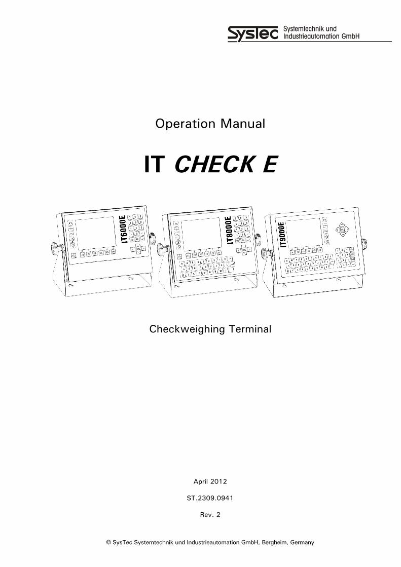
Operation Manual
IT CHECK E
Checkweighing Terminal
April 2012
ST.2309.0941
Rev. 2
© SysTec Systemtechnik und Industrieautomation GmbH, Bergheim, Germany

2 Operation Manual IT CHECK E Rev. 2

Operation Manual IT CHECK E Rev. 2 3
Operation Manual IT CHECK E
Date: April 20, 2012
File: CHECK_E_BAE.DOC
Program Version: 1.03
4 Operation Manual IT CHECK E Rev. 2
Published By: © SysTec Systemtechnik und Industrieautomation GmbH, Bergheim, Germany All rights reserved. No part of this publication may be reproduced, stored in a retrieval system, or transmitted in any form or by any means, mechanical, photocopying, recording, or otherwise, without the prior written permission of SysTec GmbH. Terms and product names mentioned in this publication are trademarks, registered trademarks or service marks of their respective owners. Use of a term should not be regarded as affecting the validity of any trademark, registered trademark or service mark.
Please Note: While every precaution has been taken in the preparation of this manual, SysTec GmbH assumes no responsibility for errors or omissions. Neither is any liability assumed for damages resulting from the use of the information contained herein. The publisher is grateful for any information and/or advice that may contribute to correct errors or omissions in following editions.
Operation Manual IT CHECK E Rev. 2 5
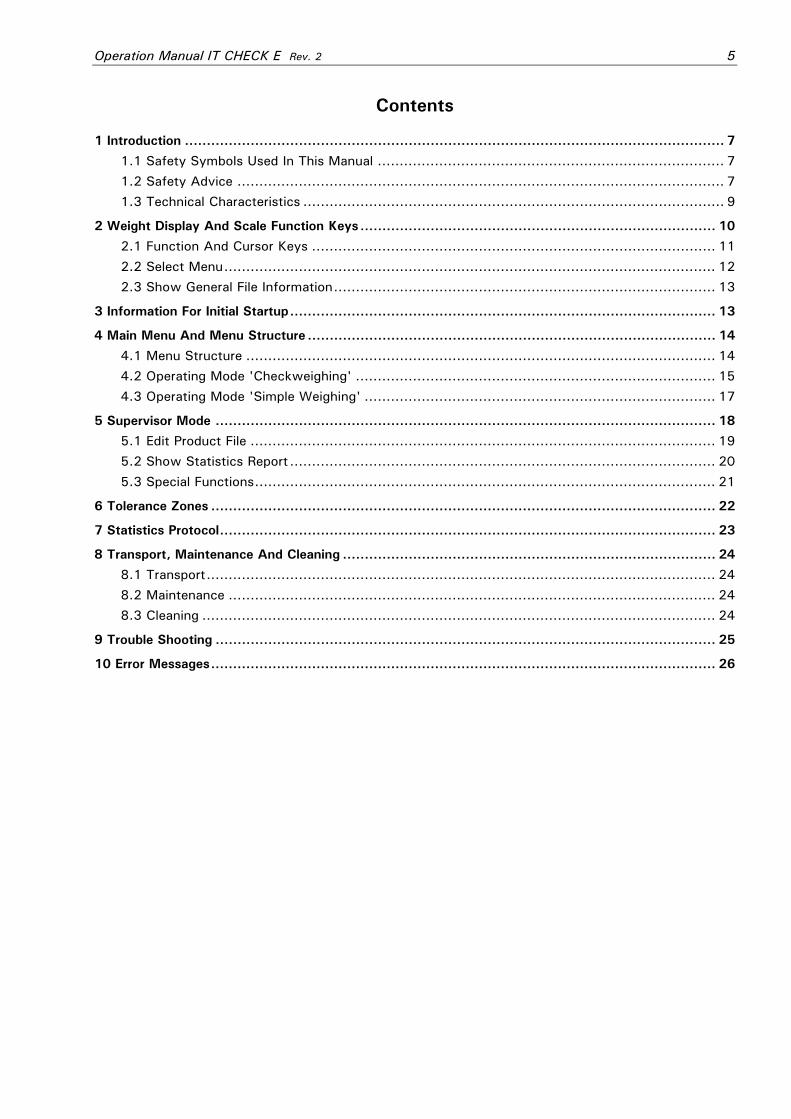
Contents
1 Introduction ........................................................................................................................... 7 1.1 Safety Symbols Used In This Manual ............................................................................... 7 1.2 Safety Advice ............................................................................................................... 7 1.3 Technical Characteristics ................................................................................................ 9
2 Weight Display And Scale Function Keys................................................................................. 10 2.1 Function And Cursor Keys ............................................................................................ 11 2.2 Select Menu................................................................................................................ 12 2.3 Show General File Information....................................................................................... 13
3 Information For Initial Startup................................................................................................. 13 4 Main Menu And Menu Structure ............................................................................................. 14
4.1 Menu Structure ........................................................................................................... 14 4.2 Operating Mode 'Checkweighing' .................................................................................. 15 4.3 Operating Mode 'Simple Weighing' ................................................................................ 17
5 Supervisor Mode .................................................................................................................. 18 5.1 Edit Product File .......................................................................................................... 19 5.2 Show Statistics Report ................................................................................................. 20 5.3 Special Functions......................................................................................................... 21
6 Tolerance Zones ................................................................................................................... 22 7 Statistics Protocol................................................................................................................. 23 8 Transport, Maintenance And Cleaning ..................................................................................... 24
8.1 Transport.................................................................................................................... 24 8.2 Maintenance ............................................................................................................... 24 8.3 Cleaning ..................................................................................................................... 24
9 Trouble Shooting .................................................................................................................. 25 10 Error Messages................................................................................................................... 26

6 Operation Manual IT CHECK E Rev. 2

Operation Manual IT CHECK E Rev. 2 7
1 Introduction IT CHECK E is a versatile checkweighing terminal for automatic control of piece goods. Due to its modular design and setup options, it can be easily adapted to a variety of weighing applications with belt and/or roller conveyors.
1.1 Safety Symbols Used In This Manual Safety relevant information is shown with corresponding symbols as follows:
W A R N I N G Failure to observe this precaution could result in serious injuries or fatal accidents. Please make absolutely sure that these precautions are observed in order to ensure safe operation of the equipment.
CAUTION Failure to observe this precaution could result in damage to or destruction of the equipment or bodily harm! Please make absolutely sure that these precautions are observed in order to ensure safe operation of the equipment.
This symbol indicates a step in the operating sequence.
Note: This indicates an advice for the designated use of the equipment and/or additional information to avoid inappropriate handling.
1.2 Safety Advice
W A R N I N G Disconnect all power to this instrument before opening the housing! Risk of electrical shock!
W A R N I N G Exercise utmost care when making checks, tests and adjustments that can actuate movable parts such as feeding devices, gates, flaps, conveyors, etc. Make absolutely sure that nobody is within reach of movable parts.
W A R N I N G This unit must not be operated in a potentially explosive atmosphere! It is the sole responsibility of the user to classify the area of installation and make sure that absolutely no potentially explosive atmosphere can be present at any time!
CAUTION Input voltage of the instrument must comply with local mains supply!
CAUTION If the line cord with connector is used as the means to separate the instrument from the mains, the wall outlet must be installed close to the instrument and must be easily accessible! If a permanently connected mains cable is used, an easily accessible separator must be included in the supply circuit!
CAUTION The power supply unit of the weighing terminal provides SELV voltages in accordance with EN 60950. Make sure that any peripheral device connected to the weighing terminal containing its own power supply also uses SELV voltages!
8 Operation Manual IT CHECK E Rev. 2
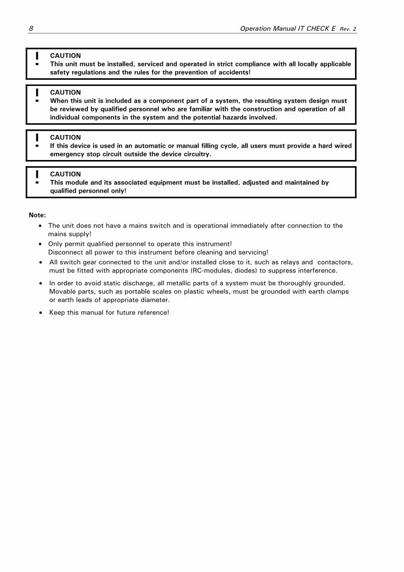
CAUTION This unit must be installed, serviced and operated in strict compliance with all locally applicable safety regulations and the rules for the prevention of accidents!
CAUTION When this unit is included as a component part of a system, the resulting system design must be reviewed by qualified personnel who are familiar with the construction and operation of all individual components in the system and the potential hazards involved.
CAUTION If this device is used in an automatic or manual filling cycle, all users must provide a hard wired emergency stop circuit outside the device circuitry.
CAUTION This module and its associated equipment must be installed, adjusted and maintained by qualified personnel only!
Note:
• The unit does not have a mains switch and is operational immediately after connection to the mains supply!
• Only permit qualified personnel to operate this instrument! Disconnect all power to this instrument before cleaning and servicing!
• All switch gear connected to the unit and/or installed close to it, such as relays and contactors, must be fitted with appropriate components (RC-modules, diodes) to suppress interference.
• In order to avoid static discharge, all metallic parts of a system must be thoroughly grounded. Movable parts, such as portable scales on plastic wheels, must be grounded with earth clamps or earth leads of appropriate diameter.
• Keep this manual for future reference!

Operation Manual IT CHECK E Rev. 2 9
1.3 Technical Characteristics
Checkweighing Of Piece Goods: • Operation in dynamic mode with one or two light barriers; • Operation in dynamic mode without light barriers; • Start / stop operation with one or two light barriers;
Tolerance Check:
• Classification of test objects into one of five product-related tolerance zones; Files:
• Product file for 99 products with pertaining target weights and tolerance zones. Simple product selection via 2-digit ident-No.;
• Statistics file with product-related memories for total number of pieces, totals per zone, standard deviation, and mean value;
Controls:
• Signal outputs for belt or roller conveyors;
• Operation selectable weight-triggered (without light barriers) or with one or two light barriers;
• Signal outputs to reject over and under weights; Printout:
• Data logging with printout of individual weights, totals, statistics and master file data; Data Transmission:
• Transmission of weighing data to host computer as background task;
• Storage of data in off-line mode; Configuration:
• Program sequence, I/O-signals, printout format, and file format can be configured via a PC-based program generator;
Construction:
• Stainless steel wall-mount / desktop housing;
• panel-mount housing.

10 Operation Manual IT CHECK E Rev. 2
2 Weight Display And Scale Function Keys
Scale Function Keys Scale Select Key (not for IT BAG E)
Set Zero Key to set the displayed scale to zero (only within zero setting range, selectable in calibration mode).
Display Select Key to switch the display between tare weight / gross weight / gross bargraph / data archive.
Tare Entry Key to enter a known tare weight in the tare line, confirm with Enter-key. *1
Tare Key alternately taring of currently displayed weight or clearing the tare weight.
Note: The scale function keys of the IT9000E terminal are located on the right hand side of the display. Electronic Marking Plate (only for single- and dual-range and two-interval scales) Scale-No. W1 Always 1 for IT DOS E.
Max Load e.g.: Max 3000kg Maximum load (without additive tare), selectable in calibration mode.
Min Load e.g.: Min 20kg Permissible minimum load.
Division e / d e.g.: e=d=1kg Approved division e and display graduation d (in most cases e = d).
Weight Display Scale-No. / W1 Always 1 for IT BAG E. No. Of Weighing Range W1.1 … W1.3 Partial weighing range for multiple-range scale.
No-Motion Symbol Settled weight (printing / storing possible).
Gross Weight Or e.g. 1250 Switching from gross weight to Net Weight e.g. 650 Net net weight with Tare-key.
Net Weight Symbol Net Scale is tared.
Unit e.g. kg Weight unit, selectable in calibration mode.
Auxiliary Display (switchable via Display Select Key)
Tare 12.9kgT Display of tare weight
Gross 1000kg Display of gross weight
Gross weight bargraph (zero to max load)
Date 15.04.11 06:18:53 Show date and time
1000 Large-character weight display for improved reading from greater distance, (only if onscreen electronic marking plate is disabled).
Operation Manual IT CHECK E Rev. 2 11
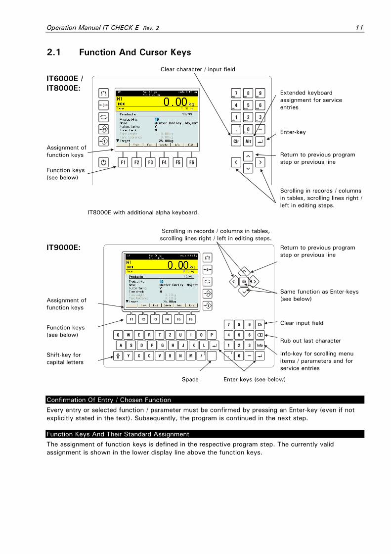
2.1 Function And Cursor Keys
Clear character / input field
IT6000E / IT8000E:
Assignment of function keys
Function keys (see below)
IT8000E with additional alpha keyboard.
Extended keyboard assignment for service entries
Enter-key
Return to previous program step or previous line
Scrolling in records / columns in tables, scrolling lines right / left in editing steps.
Scrolling in records / columns in tables, scrolling lines right / left in editing steps.
IT9000E:
Assignment of function keys
Function keys (see below)
Shift-key for capital letters
Return to previous program step or previous line
Same function as Enter-keys (see below)
Clear input field
Rub out last character
Info-key for scrolling menu items / parameters and for service entries
Space Enter keys (see below)
Confirmation Of Entry / Chosen Function Every entry or selected function / parameter must be confirmed by pressing an Enter-key (even if not explicitly stated in the text). Subsequently, the program is continued in the next step.
Function Keys And Their Standard Assignment The assignment of function keys is defined in the respective program step. The currently valid assignment is shown in the lower display line above the function keys.
12 Operation Manual IT CHECK E Rev. 2
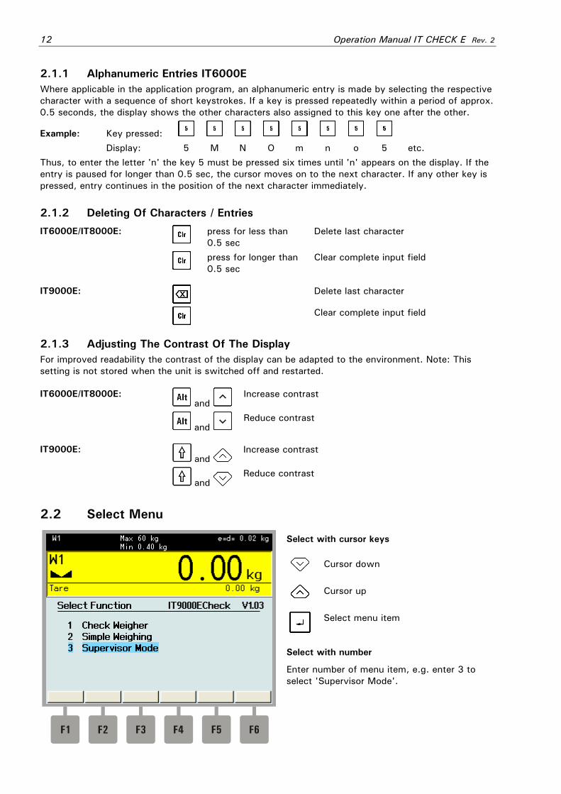
2.1.1 Alphanumeric Entries IT6000E Where applicable in the application program, an alphanumeric entry is made by selecting the respective character with a sequence of short keystrokes. If a key is pressed repeatedly within a period of approx. 0.5 seconds, the display shows the other characters also assigned to this key one after the other.
Example: Key pressed: Display: 5 M N O m n o 5 etc. Thus, to enter the letter 'n' the key 5 must be pressed six times until 'n' appears on the display. If the entry is paused for longer than 0.5 sec, the cursor moves on to the next character. If any other key is pressed, entry continues in the position of the next character immediately. 2.1.2 Deleting Of Characters / Entries
IT6000E/IT8000E:
press for less than 0.5 sec
Delete last character
press for longer than 0.5 sec
Clear complete input field
IT9000E:
Delete last character
Clear complete input field
2.1.3 Adjusting The Contrast Of The Display For improved readability the contrast of the display can be adapted to the environment. Note: This setting is not stored when the unit is switched off and restarted.
IT6000E/IT8000E: and
Increase contrast
and
Reduce contrast
IT9000E: and
Increase contrast
and
Reduce contrast
2.2 Select Menu
Select with cursor keys
Cursor down
Cursor up
Select menu item
Select with number
Enter number of menu item, e.g. enter 3 to select 'Supervisor Mode'.

Operation Manual IT CHECK E Rev. 2 13
2.3 Show General File Information
The arrow symbol indicates that there are further parameters, proceed with or Enter-key.
Display of number of stored records / capacity of data base.
3 Information For Initial Startup
When the system is powered up for the first time, please enter first master file data such as product file, see also section 'Supervisor Mode'.

14 Operation Manual IT CHECK E Rev. 2
4 Main Menu And Menu Structure After power-up and start of the operating system the main menu is displayed.
1 Checkweighing Operating mode 'Checkweighing'
2 Simple Weighing Operating mode 'Simple Weighing'
3 Supervisor Mode Editing of data and parameters
4.1 Menu Structure Main menu:
1 Checkweighing
2 Simple Weighing
3 Supervisor Mode Edit menu:
1 Product file
2 Statistics
3 Special entries
4 Service parameters
If autostart is activated in Supervisor Mode, the program starts with the chosen function and the main menu is skipped. Press F6 to return to the main menu.
Operation Manual IT CHECK E Rev. 2 15
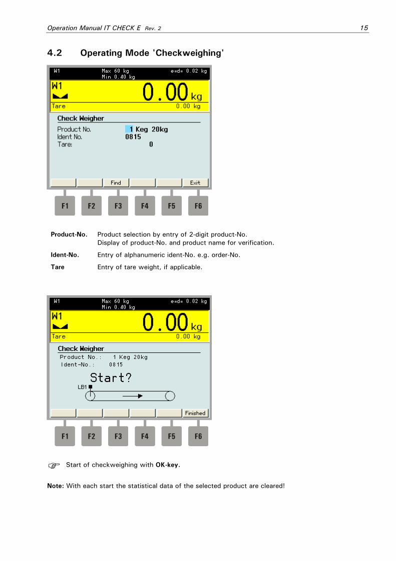
4.2 Operating Mode 'Checkweighing'
Product-No. Product selection by entry of 2-digit product-No. Display of product-No. and product name for verification.
Ident-No. Entry of alphanumeric ident-No. e.g. order-No.
Tare Entry of tare weight, if applicable.
Start of checkweighing with OK-key.
Note: With each start the statistical data of the selected product are cleared!
16 Operation Manual IT CHECK E Rev. 2
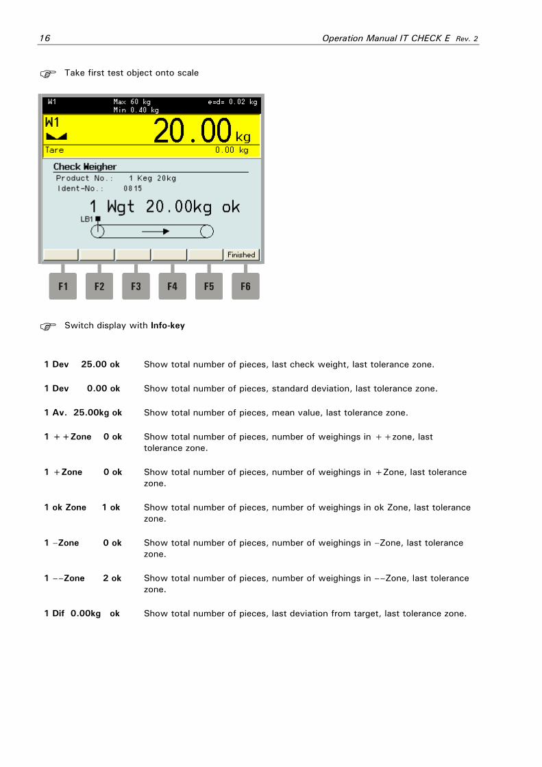
Take first test object onto scale
Switch display with Info-key
1 Dev 25.00 ok Show total number of pieces, last check weight, last tolerance zone.
1 Dev 0.00 ok Show total number of pieces, standard deviation, last tolerance zone.
1 Av. 25.00kg ok Show total number of pieces, mean value, last tolerance zone.
1 ++Zone 0 ok Show total number of pieces, number of weighings in ++zone, last tolerance zone.
1 +Zone 0 ok Show total number of pieces, number of weighings in +Zone, last tolerance zone.
1 ok Zone 1 ok Show total number of pieces, number of weighings in ok Zone, last tolerance zone.
1 –Zone 0 ok Show total number of pieces, number of weighings in –Zone, last tolerance zone.
1 ––Zone 2 ok Show total number of pieces, number of weighings in ––Zone, last tolerance zone.
1 Dif 0.00kg ok Show total number of pieces, last deviation from target, last tolerance zone.
Operation Manual IT CHECK E Rev. 2 17
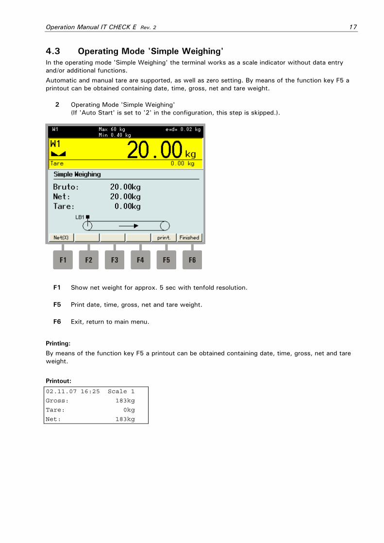
4.3 Operating Mode 'Simple Weighing' In the operating mode 'Simple Weighing' the terminal works as a scale indicator without data entry and/or additional functions. Automatic and manual tare are supported, as well as zero setting. By means of the function key F5 a printout can be obtained containing date, time, gross, net and tare weight.
2 Operating Mode 'Simple Weighing' (If 'Auto Start' is set to '2' in the configuration, this step is skipped.).
F1 Show net weight for approx. 5 sec with tenfold resolution.
F5 Print date, time, gross, net and tare weight.
F6 Exit, return to main menu.
Printing: By means of the function key F5 a printout can be obtained containing date, time, gross, net and tare weight. Printout:
02.11.07 16:25 Scale 1
Gross: 183kg
Tare: 0kg
Net: 183kg
18 Operation Manual IT CHECK E Rev. 2
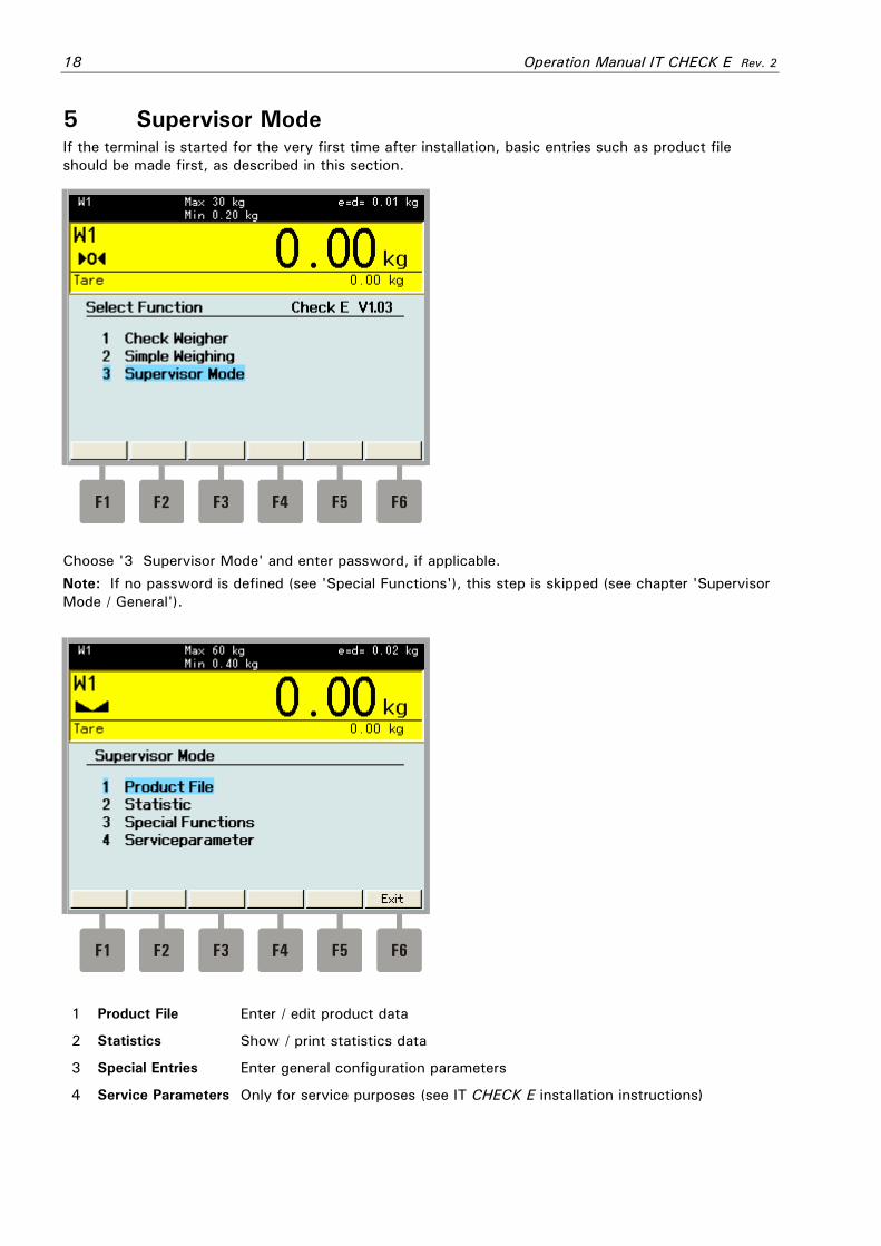
5 Supervisor Mode If the terminal is started for the very first time after installation, basic entries such as product file should be made first, as described in this section.
Choose '3 Supervisor Mode' and enter password, if applicable. Note: If no password is defined (see 'Special Functions'), this step is skipped (see chapter 'Supervisor Mode / General').
1 Product File Enter / edit product data
2 Statistics Show / print statistics data
3 Special Entries Enter general configuration parameters
4 Service Parameters Only for service purposes (see IT CHECK E installation instructions)

Operation Manual IT CHECK E Rev. 2 19
5.1 Edit Product File In the product file nominal values and tolerances for up to 99 different products can be stored.
Product-No. Entry of 2-digit product-No.
Name Entry of product name
Nominal Wgt Entry of nominal weight for checkweighing. Note: In applications subject to W&M approval, the nominal weight must be equal or greater than the scale's minimum weight.
–– Tolerance Entry of ––tolerance in divisions of calibrated weight.
Y Eject test objects under the ––tolerance threshold. Removed test objects are not entered in the statistics.
–– Eject?
N Do not eject test objects.
– Tolerance Entry of –tolerance in divisions of calibrated weight.
Y Eject test objects under the –tolerance threshold. Removed test objects are not entered in the statistics.
– Eject?
N Do not eject test objects.
+Tolerance Entry of +tolerance in divisions of calibrated weight.
Y Eject test objects under the +tolerance threshold. Removed test objects are not entered in the statistics.
+ Eject?
N Do not eject test objects.
++Tolerance Entry of ++tolerance in divisions of calibrated weight.
Y Eject test objects under the ++tolerance threshold. Removed test objects are not entered in the statistics.
++ Eject?
N Do not eject test objects.
TU1 TU1 of this product.
TU2 TU2 of this product.
TO1 TO1 of this product.
TO2 TO2 of this product.

20 Operation Manual IT CHECK E Rev. 2
5.2 Show Statistics Report
Selection of product by entry of 2-digit product-No. and display of product name.
Total Pieces Number of all weighings of this product
Ejected Pieces Show number of ejected pieces of this product.
–– Pieces Number of weighings of this product in the – – zone
– Pieces Number of weighings of this product in the – zone
ok Pieces Number of weighings of this product in the ok-zone
+ Pieces Number of weighings of this product in the +zone
++ Pieces Number of weighings of this product in the ++ zone
Average Wgt. Average of all weighings of this product
Sigma Standard deviation of all weighings of this product
Total (kg) Total weight of all weighings of this product
Total ^2 Square of total weight of all weighings of this product
Setting 'W&M approved' and 'Target <= 10kg' or 'Target <= 10000g'
Under TU1 Number of weighings of this product under TU1
Under TU2 Number of weighings of this product under TU2
Over TO1 Number of weighings of this product over TO1
Over TO2 Number of weighings of this product over TO2
Note: With each new start the statistical data of the selected product are cleared!

Operation Manual IT CHECK E Rev. 2 21
5.3 Special Functions
Date Enter date
Time Enter time in 24h format
Consec.-No. Not applicable to IT CHECK E
Delete ID-No.? Y With each new start of the checkweighing function, the ID-No. must be entered.
N The ID-No. entered last is maintained
Selects ≤ function after power up
none Autostart disabled
Check Weighing After power up the program starts the function 'Check Weighing'
Autostart
Simple Weighing After power up the program starts the function 'Simple Weighing'
Password Specify password to protect access to entries. If no password is entered, password protection is disabled.
22 Operation Manual IT CHECK E Rev. 2
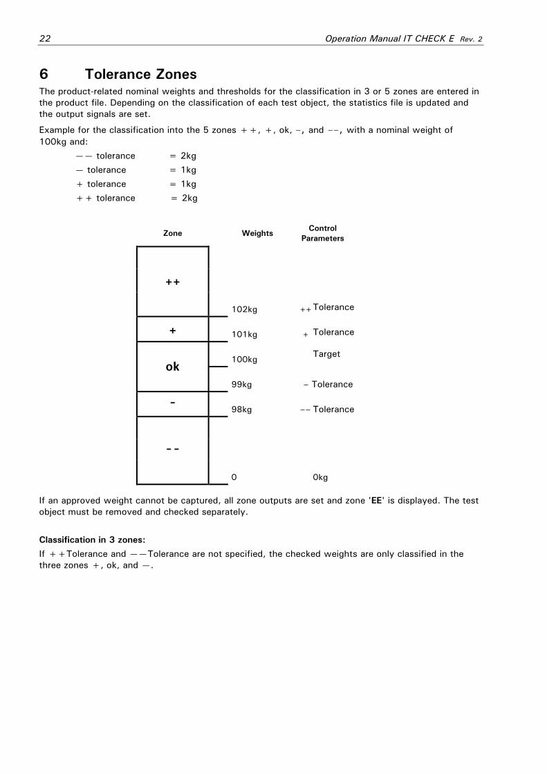
6 Tolerance Zones The product-related nominal weights and thresholds for the classification in 3 or 5 zones are entered in the product file. Depending on the classification of each test object, the statistics file is updated and the output signals are set.
Example for the classification into the 5 zones ++, +, ok, –, and ––, with a nominal weight of 100kg and:
—— tolerance = 2kg — tolerance = 1kg + tolerance = 1kg ++ tolerance = 2kg
Zone Weights Control Parameters
++
102kg ++ Tolerance
+ 101kg + Tolerance
100kg
Target ok
99kg – Tolerance
- 98kg –– Tolerance
--
0 0kg
If an approved weight cannot be captured, all zone outputs are set and zone 'EE' is displayed. The test object must be removed and checked separately. Classification in 3 zones: If ++Tolerance and ——Tolerance are not specified, the checked weights are only classified in the three zones +, ok, and —.

Operation Manual IT CHECK E Rev. 2 23
7 Statistics Protocol If the nominal weight is ≤ 10 kg (or ≤ 10000g), a statistics protocol is printed for each finished batch. Rejected test objects are shown separately and are ignored for the calculation of the mean value. The limits for TU2, TU1, TO2 and TO1 are calculated automatically and do not necessarily comply with the thresholds set for the individual zones. Test objects under TU2 must be ejected. Example for printout:
Statistics
From 06.08.03 17:47 to 06.08.03 17:48
========================================
Scale-No. 1
Ident-No. 1111111111
Product-No. 1 AAAAAAAAAAAAAAAA
Target weight = Nominal weight 0.5kg
Number of check weighings 8
Number of ejected pieces 0
Under TU2 = 0.47kg 0
Under TU1 = 0.485kg 0
Over TO1 = 0.515kg 1
Over TO2 = 0.53kg 0
Mean value 0.5087kg
Standard deviation 0.0113kg
Mean tare weight 0.390kg
24 Operation Manual IT CHECK E Rev. 2
8 Transport, Maintenance And Cleaning 8.1 Transport Notes:
• Transport and storage of electronic components such as boards, EPROMS, etc. must only be made in suitable anti-static ESD bags or cases.
• Storage temperature –25 to +70°C at 95% max. relative humidity without condensation.
8.2 Maintenance
CAUTION This unit and its associated equipment must be maintained by qualified personnel only, who are familiar with the construction and operation of all equipment in the system and the potential hazards involved. Failure to observe these precautions could result in bodily injury! Disconnect all power to this unit before servicing!
The ITX000E terminal is designed to require a minimum of maintenance and service, however, depending on the environmental conditions a visual inspection at regular intervals is recommended. The frequency at which normal maintenance (cleaning and inspection) should be performed, when installed in a clean office environment, should be twice a year. However, if the unit is subject to a dusty or dirty environment the frequency should be increased as required. At these inspections it should be made sure that all connected cables are undamaged and that all connectors are tightly fastened. Maintenance of scale platforms is required at regular intervals depending on use and environment. The accuracy of scales can be affected by dirt, foreign objects, etc. and appropriate maintenance is strongly recommended. Also recommended is the calibration with certified test weights at regular intervals.
8.3 Cleaning
CAUTION Disconnect all power to this unit before servicing!
Clean the keyboard and covers with a soft clean cloth that has been dampened with a mild window type cleaner. Do NOT use any type of industrial solvent or the finish of the unit may be damaged. Do not spray cleaner directly on the unit

Operation Manual IT CHECK E Rev. 2 25
9 Trouble Shooting
CAUTION This unit does not contain any customer serviceable parts! Only permit qualified personnel to service this equipment. Exercise care when making checks, tests, and adjustments!
If any problem arises that has not been explained above, please follow this check list:
• Power supply on and line cord undamaged (visual inspection)? • All cables connecting to scales and peripheral devices undamaged (visual inspection)? • Connectors fitted correctly and tightly secured at peripheral devices (visual inspection)?
If operational difficulties are encountered that cannot be rectified by means of this manual, obtain as much information as possible regarding the particular trouble, as this may eliminate a lengthy, detailed checkout procedure. If possible, try first to determine the conditions under which the problem occurs. Try to find out whether the appearance of the difficulties can be reproduced under the same conditions.
For the systematic analysis of an unknown problem the information as listed below is required:
• Serial-No. of the unit and its peripheral components • Program version as displayed on power up • Exact wording of any error message displayed • Type and model of peripheral devices related to the problem (e.g. scale, printer, etc.)
To obtain professional assistance contact your service station stating the information listed above.
CAUTION It is suggested that assistance from trained service personnel be requested in the event a problem should arise that is beyond the scope of this instruction manual.
26 Operation Manual IT CHECK E Rev. 2
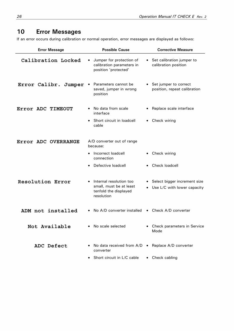
10 Error Messages If an error occurs during calibration or normal operation, error messages are displayed as follows:
Error Message Possible Cause Corrective Measure
Calibration Locked • Jumper for protection of calibration parameters in position 'protected'
• Set calibration jumper to calibration position
Error Calibr. Jumper • Parameters cannot be saved, jumper in wrong position
• Set jumper to correct position, repeat calibration
• No data from scale interface
• Replace scale interface Error ADC TIMEOUT
• Short circuit in loadcell cable
• Check wiring
A/D converter out of range because:
• Incorrect loadcell connection
• Check wiring
Error ADC OVERRANGE
• Defective loadcell • Check loadcell
Resolution Error • Internal resolution too small, must be at least tenfold the displayed resolution
• Select bigger increment size
• Use L/C with lower capacity
ADM not installed • No A/D converter installed • Check A/D converter
Not Available • No scale selected • Check parameters in Service Mode
• No data received from A/D converter
• Replace A/D converter ADC Defect
• Short circuit in L/C cable • Check cabling
Operation Manual IT CHECK E Rev. 2 27
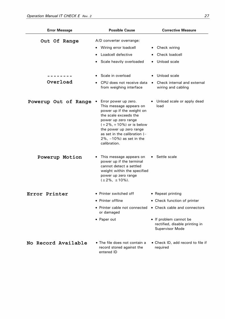
Error Message Possible Cause Corrective Measure
A/D converter overrange:
• Wiring error loadcell • Check wiring
• Loadcell defective • Check loadcell
Out Of Range
• Scale heavily overloaded • Unload scale
• Scale in overload • Unload scale -------- Overload • CPU does not receive data
from weighing interface • Check internal and external
wiring and cabling
Powerup Out of Range • Error power up zero. This message appears on power up if the weight on the scale exceeds the power up zero range (+2%,+10%) or is below the power up zero range as set in the calibration (–2%, –10%) as set in the calibration.
• Unload scale or apply dead load
Powerup Motion • This message appears on power up if the terminal cannot detect a settled weight within the specified power up zero range (±2%, ±10%).
• Settle scale
• Printer switched off • Repeat printing
• Printer offline • Check function of printer
• Printer cable not connected or damaged
• Check cable and connectors
Error Printer
• Paper out • If problem cannot be rectified, disable printing in Supervisor Mode
No Record Available • The file does not contain a record stored against the entered ID
• Check ID, add record to file if required

28 Operation Manual IT CHECK E Rev. 2
Error Message Possible Cause Corrective Measure
File Full! • No more free memory for additional records
• Delete records no longer used
Error Transport • The first light barrier has been actuated before the last weighing cycle was terminated
• Check test objects on conveyor
• Check positioning of light barriers
Error Zero setting • The scale must be set to zero at intervals not longer than 15 mi
• Set scale to zero
Memory Full • The temporary memory for 1500 weighings is full
• Set up host computer to receive data or switch off data transmission at weighing terminal
Further self-explanatory error messages may appear.


