Checkbox Compact - Festo€¦ · · 2018-04-21Checkbox Compact Module with control panel, ......
141
Manual Checkbox Compact Type CHB-C-X Manual 533412 en 1102d [757659] Checkbox Compact
-
Upload
duongnguyet -
Category
Documents
-
view
213 -
download
0
Transcript of Checkbox Compact - Festo€¦ · · 2018-04-21Checkbox Compact Module with control panel, ......
ManualCheckbox Compact
Type CHB-C-X
Manual533412en 1102d[757659]
Checkbox Compact

Festo Checkbox ® is a registered trademark of Festo AG & Co. KG,D-73726 Esslingen, Germany

Contents and general instructions
IFesto P.BE-CB-COMP-EN en 1102d
Original de. . . . . . . . . . . . . . . . . . . . . . . . . . . . . . . . . . . . . . .
Edition en 1102d. . . . . . . . . . . . . . . . . . . . . . . . . . . . . . . . . .
Designation P.BE-CB-COMP-EN. . . . . . . . . . . . . . . . . . . . . .
Order no. 533412. . . . . . . . . . . . . . . . . . . . . . . . . . . . . . . . . .
� (Festo AG & Co. KG, D-73726 Esslingen, Germany, 2011)Internet: http://www.festo.comE-mail: [email protected]
The reproduction of this document and disclosure to thirdparties and the utilisation or communication of its contentswithout explicit authorization is prohibited. Offenders willbe held liable for compensation of damages. All rightsreserved, in particular the right to carry out patent, utilitymodel or ornamental design registrations.

Contents and general instructions
II Festo P.BE-CB-COMP-EN en 1102d
Contents and general instructions
IIIFesto P.BE-CB-COMP-EN en 1102d
Contents
Intended use VI. . . . . . . . . . . . . . . . . . . . . . . . . . . . . . . . . . . . . . . . . . . . . . . . . . . . . . . . . .
Operating requirements VIII. . . . . . . . . . . . . . . . . . . . . . . . . . . . . . . . . . . . . . . . . . . . . . . . .Target group VIII. . . . . . . . . . . . . . . . . . . . . . . . . . . . . . . . . . . . . . . . . . . . . . . . . . . . . . . . . .
Service VIII. . . . . . . . . . . . . . . . . . . . . . . . . . . . . . . . . . . . . . . . . . . . . . . . . . . . . . . . . . . . . . .Scope of delivery VIII. . . . . . . . . . . . . . . . . . . . . . . . . . . . . . . . . . . . . . . . . . . . . . . . . . . . . . .
Important user instructions IX. . . . . . . . . . . . . . . . . . . . . . . . . . . . . . . . . . . . . . . . . . . . . .
Notes on the use of this manual XII. . . . . . . . . . . . . . . . . . . . . . . . . . . . . . . . . . . . . . . . . . .Documentation on the Checkbox XII. . . . . . . . . . . . . . . . . . . . . . . . . . . . . . . . . . . . . . . . . .
Product-specific terms and abbreviations XIII. . . . . . . . . . . . . . . . . . . . . . . . . . . . . . . . . . .
1. System summary 1-1. . . . . . . . . . . . . . . . . . . . . . . . . . . . . . . . . . . . . . . . . . . . . . .
1.1 The Festo Checkbox 1-3. . . . . . . . . . . . . . . . . . . . . . . . . . . . . . . . . . . . . . . . . . . . .
1.2 Software packages for the Checkbox 1-4. . . . . . . . . . . . . . . . . . . . . . . . . . . . . . .
1.3 Functional range 1-5. . . . . . . . . . . . . . . . . . . . . . . . . . . . . . . . . . . . . . . . . . . . . . . .
1.4 Operating principle 1-6. . . . . . . . . . . . . . . . . . . . . . . . . . . . . . . . . . . . . . . . . . . . .
1.5 Buffer zone 1-9. . . . . . . . . . . . . . . . . . . . . . . . . . . . . . . . . . . . . . . . . . . . . . . . . . . .
2. Fitting and commissioning 2-1. . . . . . . . . . . . . . . . . . . . . . . . . . . . . . . . . . . . . . .
2.1 General instructions 2-3. . . . . . . . . . . . . . . . . . . . . . . . . . . . . . . . . . . . . . . . . . . . .
2.2 Mounting 2-4. . . . . . . . . . . . . . . . . . . . . . . . . . . . . . . . . . . . . . . . . . . . . . . . . . . . . .
2.3 Electrical connection 2-7. . . . . . . . . . . . . . . . . . . . . . . . . . . . . . . . . . . . . . . . . . . .
2.3.1 Selection of the power supply unit 2-10. . . . . . . . . . . . . . . . . . . . . . . . . .
2.3.2 Connection of the operating voltage 2-11. . . . . . . . . . . . . . . . . . . . . . . .
2.3.3 Power supply for external components 2-12. . . . . . . . . . . . . . . . . . . . . .
2.4 Adapting system parameters with CheckKon 2-13. . . . . . . . . . . . . . . . . . . . . . . . .
2.5 Commissioning the Checkbox 2-15. . . . . . . . . . . . . . . . . . . . . . . . . . . . . . . . . . . . .
2.6 Error diagnostics 2-20. . . . . . . . . . . . . . . . . . . . . . . . . . . . . . . . . . . . . . . . . . . . . . .

Contents and general instructions
IV Festo P.BE-CB-COMP-EN en 1102d
3. The I/O module 3-1. . . . . . . . . . . . . . . . . . . . . . . . . . . . . . . . . . . . . . . . . . . . . . . .
3.1 Interfaces 3-3. . . . . . . . . . . . . . . . . . . . . . . . . . . . . . . . . . . . . . . . . . . . . . . . . . . . .
3.2 ACTUATORS 3-5. . . . . . . . . . . . . . . . . . . . . . . . . . . . . . . . . . . . . . . . . . . . . . . . . . .
3.3 BUFFER/FEEDER 3-7. . . . . . . . . . . . . . . . . . . . . . . . . . . . . . . . . . . . . . . . . . . . . . .
3.4 DIAG 3-10. . . . . . . . . . . . . . . . . . . . . . . . . . . . . . . . . . . . . . . . . . . . . . . . . . . . . . . . .
3.5 ENCODER 3-12. . . . . . . . . . . . . . . . . . . . . . . . . . . . . . . . . . . . . . . . . . . . . . . . . . . . .
3.6 PLC 3-14. . . . . . . . . . . . . . . . . . . . . . . . . . . . . . . . . . . . . . . . . . . . . . . . . . . . . . . . . . .
3.6.1 Start/Stop mode 3-17. . . . . . . . . . . . . . . . . . . . . . . . . . . . . . . . . . . . . . . .
3.6.2 Controlling the teach procedure 3-19. . . . . . . . . . . . . . . . . . . . . . . . . . . .
3.6.3 Selecting the parts type 3-19. . . . . . . . . . . . . . . . . . . . . . . . . . . . . . . . . .
3.6.4 Counting function 3-23. . . . . . . . . . . . . . . . . . . . . . . . . . . . . . . . . . . . . . .
3.6.5 Actuators 3-26. . . . . . . . . . . . . . . . . . . . . . . . . . . . . . . . . . . . . . . . . . . . . .
3.6.6 Buffer zone sensors/small parts conveyor 3-27. . . . . . . . . . . . . . . . . . .
3.6.7 Fault messages 3-30. . . . . . . . . . . . . . . . . . . . . . . . . . . . . . . . . . . . . . . . .
3.6.8 Locking the control panel 3-31. . . . . . . . . . . . . . . . . . . . . . . . . . . . . . . . .
4. Teaching parts 4-1. . . . . . . . . . . . . . . . . . . . . . . . . . . . . . . . . . . . . . . . . . . . . . . . .
4.1 Preparing the Teach procedure 4-3. . . . . . . . . . . . . . . . . . . . . . . . . . . . . . . . . . . .
4.2 The Teach procedure 4-5. . . . . . . . . . . . . . . . . . . . . . . . . . . . . . . . . . . . . . . . . . . .
4.2.1 Positioning the sample parts 4-9. . . . . . . . . . . . . . . . . . . . . . . . . . . . . .
4.2.2 Observing the scatter of characteristics 4-10. . . . . . . . . . . . . . . . . . . . .
5. Testing parts 5-1. . . . . . . . . . . . . . . . . . . . . . . . . . . . . . . . . . . . . . . . . . . . . . . . . .
5.1 The test procedure 5-3. . . . . . . . . . . . . . . . . . . . . . . . . . . . . . . . . . . . . . . . . . . . . .
5.2 Test mode 5-4. . . . . . . . . . . . . . . . . . . . . . . . . . . . . . . . . . . . . . . . . . . . . . . . . . . . .
5.3 Influence of tolerance 5-7. . . . . . . . . . . . . . . . . . . . . . . . . . . . . . . . . . . . . . . . . . .
5.4 Evaluation of the test results 5-9. . . . . . . . . . . . . . . . . . . . . . . . . . . . . . . . . . . . . .
5.4.1 Checking the features 5-9. . . . . . . . . . . . . . . . . . . . . . . . . . . . . . . . . . . .
5.4.2 Checking the orientation 5-10. . . . . . . . . . . . . . . . . . . . . . . . . . . . . . . . . .
6. Maintenance 6-1. . . . . . . . . . . . . . . . . . . . . . . . . . . . . . . . . . . . . . . . . . . . . . . . . .

Contents and general instructions
VFesto P.BE-CB-COMP-EN en 1102d
A. Technical appendix A-1. . . . . . . . . . . . . . . . . . . . . . . . . . . . . . . . . . . . . . . . . . . . .
A.1 Operating malfunctions A-3. . . . . . . . . . . . . . . . . . . . . . . . . . . . . . . . . . . . . . . . . .
A.1.1 General fault finding A-3. . . . . . . . . . . . . . . . . . . . . . . . . . . . . . . . . . . . .
A.1.2 Fault messages and warnings A-4. . . . . . . . . . . . . . . . . . . . . . . . . . . . . .
A.2 Status displays on the control panel A-9. . . . . . . . . . . . . . . . . . . . . . . . . . . . . . . .
A.3 Examples for calculation of the features A-12. . . . . . . . . . . . . . . . . . . . . . . . . . . . .
A.3.1 Band width and tolerance A-12. . . . . . . . . . . . . . . . . . . . . . . . . . . . . . . . .
A.3.2 Scatter of characteristics A-14. . . . . . . . . . . . . . . . . . . . . . . . . . . . . . . . .
A.3.3 Inspection part deviation A-15. . . . . . . . . . . . . . . . . . . . . . . . . . . . . . . . .
A.4 Connections A-17. . . . . . . . . . . . . . . . . . . . . . . . . . . . . . . . . . . . . . . . . . . . . . . . . . .
A.5 Technical data A-22. . . . . . . . . . . . . . . . . . . . . . . . . . . . . . . . . . . . . . . . . . . . . . . . . .
A.6 Accessories A-25. . . . . . . . . . . . . . . . . . . . . . . . . . . . . . . . . . . . . . . . . . . . . . . . . . . .
B. Index B-1. . . . . . . . . . . . . . . . . . . . . . . . . . . . . . . . . . . . . . . . . . . . . . . . . . . . . . . . .

Contents and general instructions
VI Festo P.BE-CB-COMP-EN en 1102d
Intended use
The Festo Checkbox® has been designed for use undernormal operating conditions in closed rooms in industrialinstallations.
The Checkbox Compact described in this manual is intendedexclusively for use as follows:for contactless checking of the position and quality of smallparts e.g. screws, springs, bolts, which pass through on aconveyor belt.
Use the Checkbox only as follows:
– as intended in an industrial environment
– in perfect technical condition
– in original status without unauthorised alterations. Onlythe conversions or modifications described in the docu-mentation supplied with the product are permitted. Theguarantee will become invalid if the Checkbox is opened.
The maximum values specified for pressures, temperatures,electrical connections etc. must not be exceeded.
Please observe the standards specified in the relevantchapters and comply with the regulations of the trade associ-ation and the German Technical Control Board (TÜV), the VDEconditions as well as the relevant national regulations.
Contents and general instructions
VIIFesto P.BE-CB-COMP-EN en 1102d
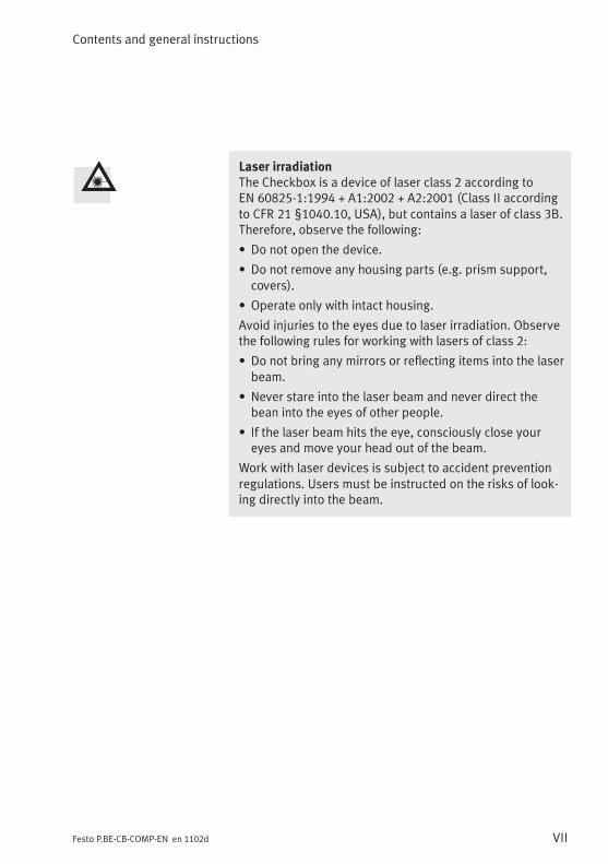
Laser irradiationThe Checkbox is a device of laser class 2 according toEN 60825-1:1994 + A1:2002 + A2:2001 (Class II accordingto CFR 21 §1040.10, USA), but contains a laser of class 3B.Therefore, observe the following:
• Do not open the device.
• Do not remove any housing parts (e.g. prism support,covers).
• Operate only with intact housing.
Avoid injuries to the eyes due to laser irradiation. Observethe following rules for working with lasers of class 2:
• Do not bring any mirrors or reflecting items into the laserbeam.
• Never stare into the laser beam and never direct thebean into the eyes of other people.
• If the laser beam hits the eye, consciously close youreyes and move your head out of the beam.
Work with laser devices is subject to accident preventionregulations. Users must be instructed on the risks of look-ing directly into the beam.

Contents and general instructions
VIII Festo P.BE-CB-COMP-EN en 1102d
Operating requirements
– The features of the conveyed part which determine theorientation and quality must be recognizable anddistinguishable for the Checkbox:
– It must be possible to integrate the Checkbox in thematerial flow.
Target group
This manual is intended exclusively for technicians trained incontrol and automation technology who have experience ininstalling and commissioning electronic systems.
Service
Please consult your local Festo Service if you have anytechnical problems.
Scope of delivery
Checkbox Compact Module with control panel, I/O interface, laser beam and camera
Documentation Checkbox Compact manual
Accessories 24-pin cable for connecting the PLC
Contents and general instructions
IXFesto P.BE-CB-COMP-EN en 1102d
Important user instructions
Danger categories
This manual contains instructions on the possible dangerswhich may occur if the product is not used correctly. Theseinstructions are marked (Warning, Caution, etc.), printed on ashaded background and marked additionally with a picto-gram. A distinction is made between the following dangerwarnings:
WarningThis means that failure to observe this instruction mayresult in serious personal injury and/or damage toproperty.
CautionThis means that failure to observe this instruction mayresult in personal injury and/or damage to property.
NoteThis means that failure to observe this instruction mayresult in damage to property.
The following pictograms also mark passages in the textwhich warn about the incorrect handling of certaincomponents.
Electrostatically sensitive devices. Incorrect handling canresult in damage to components.
Contents and general instructions
X Festo P.BE-CB-COMP-EN en 1102d
Danger of injury caused by laser irradiationDo not look into the laser beam. Incorrect handling canlead to injury to the eye and/or skin.
Identification of specific information
The following pictograms designate texts that contain specialinformation.
Pictograms
InformationMarks recommendations, tips and references to otherinformation sources.
AccessoriesMarks information on suitable accessories.
EnvironmentMarks sections dealing with environmentally protectivemeasures.
Text markings
� Bullet points indicate activities that may be carried out inany order.
1. Figures denote activities which must be carried out in thenumerical order specified.
– Hyphens indicate general activities.
Contents and general instructions
XIFesto P.BE-CB-COMP-EN en 1102d
Conventions
– The names of the operating, display and connectingelements are represented in the text in upper case letters,e.g. START, TEACH.
– Menu commands of the software are framed in brackets,e.g. in the menu [Window], the command [System parame-ters] opens the window for creating parameters.
– For selections within tree structures, e.g. for setting thesystem parameters in CheckKon, the paths are markedwith a square. You will therefore find e.g. in the path� System� Operating modes the parameter� Lock theTeach button = Off.
– Inputs and outputs of the plug connectors are specifiedwith the pin number as follows:Input pin 1 I/1Output pin 2 O/2
– Plug connectors are represented as when viewed on thedevice. This representation corresponds to the view of the(cable) connections which are to be wired.

Contents and general instructions
XII Festo P.BE-CB-COMP-EN en 1102d
Notes on the use of this manual
This manual refers to the standard designs of the CheckboxCompact type CHB-C-X with operating system version 3.x.
When the Checkbox is switched on, the version number of theoperating system will be shown briefly (see Chapter 2.5).
The options and parameters available depend on theoperating system, the type of connected Checkbox and on thefactory pre-settings. Customer-specific designs may differ intechnical data, parameter settings and method of functioning.
The pre-setting of the Checkbox can be modified if requiredwith the software packages CheckKon (function “Modifysystem”) or CheckOpti (see Chapter 1.2).
Documentation on the Checkbox
Information on using the Checkbox can be found in thefollowing manuals:
Documentation Contents
Manual for checkbox CHB-C-X– P.BE-CB-COMP-...
Description of the function,commissioning, operation andmaintenance of the Checkbox.
Manuals on the software packages– Software CheckKon P.SW-KON– Software CheckOpti P.SW-OPTI
– Operation of the CheckKon software– Operation of the CheckOpti software
Tab. 0/1: Documentation on the Checkbox

Contents and general instructions
XIIIFesto P.BE-CB-COMP-EN en 1102d
Product-specific terms and abbreviations
Term/abbreviation Significance
AUTO mode Operating mode of the Checkbox for automatic parts testing(pre-set when CHB-C-X is started).
CHB-C-X Adeviceof the type CheckboxCompact (without transportingdevice) foridentifying conveyed parts of a parts type.
C-value During the Teach procedure the C-value shows the extent of thescatter of characteristics of the sample parts. The C-value specifiesthe maximum value of the scatter of characteristics for the currentfeature which differs to the greatest extent.
Deviation The Checkbox assesses the feature of an inspection part which differsmost from the Teach data. The smaller the value of the inspection partdeviation, the more accurately the inspection part corresponds to thesample parts.
Feature Characteristic features are ascertained from the contour data of thesample and inspection parts. These are e.g. length, height, etc. as wellas a feature for each configuration tool (CheckOpti).
Good part An inspection part on which all features lie within the tolerance.
Inspection parts All parts shown during the test procedure.
Laser class Labelling of the laser beam according to EN 60825-1:1994 + A1:2002+ A2:2001. Laser devices are classified according to increasing degreeof danger into classes 1, 2, 3A, 3B and 4.Class 2An accidental, brief exposure (up to 0.25s) will not damage the eye.With longer lasting exposure, damage to the eye is possible.Laser devices of class 2 may be used without further protective meas-ures, providing it can be guaranteed that during operation the user isnot required to look intentionally over a long period (longer than0.25 s), or to look repeatedly into the laser beam or mirror-reflectedlaser beam.Class 3BLasers of class 3B can produce serious eye damage.Longer radiation of a class 3B laser onto the skin causes erythemaformation (reddened skin), pigmenting, burns or photochemicaldamage.

Contents and general instructions
XIV Festo P.BE-CB-COMP-EN en 1102d
Term/abbreviation Significance
Orientation The parts to be tested by the Checkbox can be placed on the conveyorbelt facing in different directions. During the Teach procedure you candefine the orientations by showing the different directions. Orientation1 is the preferred orientation (nominal orientation)
Parts type Conveyed part defined by the Teach data of the sample parts.
Reject part An inspection part on which at least one feature lies outside thetolerance.
Sample parts Good parts which have been selected for the Teach procedure andwhich possess all the features necessary for identifying the parts type.
(System) parameters Settings of the Checkbox (in some cases can only be set withconfiguration software)
Teach data All features ascertained during the Teach procedure, each withmin./max. limits and the average value.
TEACH mode Operating mode of the Checkbox in which the Teach procedure iscarried out.
Teach procedure During the Teach procedure, sample parts on the conveyor belt areshown to the Checkbox and the features are scanned. This is alsoreferred to as “Teaching parts”.
Test data The test data are the data used for the test. These correspond to theTeach data plus admitted tolerances.
Test procedure During the test procedure, inspection parts on the conveyor belt areshown to the Checkbox and graded according to their features withregard to orientation and observance of the tolerances. This is alsoreferred to as “Testing parts”.
Tolerance Factor in per cent related to the average values and which affects themin./max. limits of all features.
Tab. 0/2: Terms and abbreviations

Contents and general instructions
XVFesto P.BE-CB-COMP-EN en 1102d

System summary
1-1Festo P.BE-CB-COMP-EN en 1102d
System summary
Chapter 1

1. System summary
1-2 Festo P.BE-CB-COMP-EN en 1102d
Contents
1. System summary 1-1. . . . . . . . . . . . . . . . . . . . . . . . . . . . . . . . . . . . . . . . . . . . . . .
1.1 The Festo Checkbox 1-3. . . . . . . . . . . . . . . . . . . . . . . . . . . . . . . . . . . . . . . . . . . . .
1.2 Software packages for the Checkbox 1-4. . . . . . . . . . . . . . . . . . . . . . . . . . . . . . .
1.3 Functional range 1-5. . . . . . . . . . . . . . . . . . . . . . . . . . . . . . . . . . . . . . . . . . . . . . . .
1.4 Operating principle 1-6. . . . . . . . . . . . . . . . . . . . . . . . . . . . . . . . . . . . . . . . . . . . .
1.5 Buffer zone 1-9. . . . . . . . . . . . . . . . . . . . . . . . . . . . . . . . . . . . . . . . . . . . . . . . . . . .

1. System summary
1-3Festo P.BE-CB-COMP-EN en 1102d
1.1 The Festo Checkbox
The Festo Checkbox® enables the optical (contactless)positioning and quality inspection of conveyed parts.

1. System summary
1-4 Festo P.BE-CB-COMP-EN en 1102d
1.2 Software packages for the Checkbox
Various software packages are available for user-friendlycommissioning, optimizing and monitoring. They have beenspecially developed for the products in the Checkbox familyand can be used with all devices in the Checkbox family.
SoftwarePackage
Functions
CheckKonCheckboxConfigurator
– Display and assessment of the lastregistered test part
– Displaying and logging of the parts contouras well as the characteristics derived fromthe contour.
– Displaying the light intensity recognized bythe camera
– Displaying and printing out of the systemconfiguration
– Displaying and modifying the system para-meters
– Loading a new operating system into theCheckbox
CheckOptiCheckboxOptimizer
– Convenient teaching of the sample parts– Monitored testing of parts, displaying the
features registered– Evaluation of the inspection of workpieces
with regard to reliability (evaluation)– Graphic display of the test sequence– Optimization of the inspection of work-
pieces through manual adaptation of themin./max. values of the Teach data orthrough configuration tools
– Support in project planning, managementand documentation
Tab. 1/1: Software package
The CheckKon software package, operating system updatesand current product information on the Checkbox Compactcan be found in the Festo Internet pages under the addresswww.festo.com in the area “Support / Downloads”.

1. System summary
1-5Festo P.BE-CB-COMP-EN en 1102d
1.3 Functional range
Function
Teach function 1)
– Teaching new parts without programming– Saving the features of the taught parts type
Quality inspection 2)
– Testing the quality, e.g. with pivoted parts and milling parts– Machine-sorting of incorrect and foreign parts
Position test (nominal orientation)– Position-controlled transfer of the good parts to the following machine– Return of incorrectly oriented good parts to the small parts conveyorA check of the position and of the buffer zone can be made at the same time.
Buffer zone checkMonitoring the buffer zone with one sensor.If the buffer zone is full: return of the good parts to the small parts conveyor.If the conveyed parts form a jam on the buffer zone for a long period, the small parts conveyor will beswitched off.
Buffer zone check with switching hysteresis 3)
– Monitoring of the buffer zone with two sensors for delayed switching of the small parts conveyor(hysteresis).
Good part counting with preselected number of items 3)
A continuously running counter ascertains the sum of all good parts– Supplying of defined amounts of components through specification of a target number for good
parts.
1) Via the PLC interface: Selection of a maximum of 16 parts types if system parameter “Number ofbuffer zone sensors = 1”, “External signal input activated= no”. Factory setting, can be set withCheckKon
2) Extended quality inspection with CheckOpti (as from version 2.1)3) The system parameters must be activated or set in CheckKon
Tab. 1/2: Functional range
1. System summary
1-6 Festo P.BE-CB-COMP-EN en 1102d
1.4 Operating principle
123
4
5
6
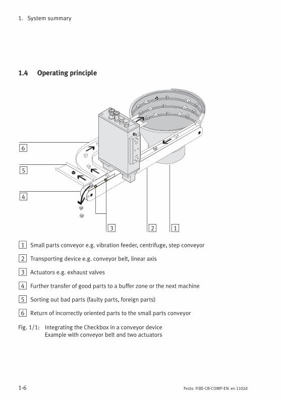
1 Small parts conveyor e.g. vibration feeder, centrifuge, step conveyor
2 Transporting device e.g. conveyor belt, linear axis
3 Actuators e.g. exhaust valves
4 Further transfer of good parts to a buffer zone or the next machine
5 Sorting out bad parts (faulty parts, foreign parts)
6 Return of incorrectly oriented parts to the small parts conveyor
Fig. 1/1: Integrating the Checkbox in a conveyor deviceExample with conveyor belt and two actuators
1. System summary
1-7Festo P.BE-CB-COMP-EN en 1102d
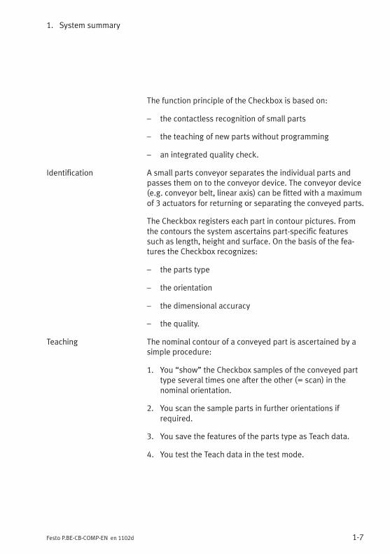
The function principle of the Checkbox is based on:
– the contactless recognition of small parts
– the teaching of new parts without programming
– an integrated quality check.
Identification A small parts conveyor separates the individual parts andpasses them on to the conveyor device. The conveyor device(e.g. conveyor belt, linear axis) can be fitted with a maximumof 3 actuators for returning or separating the conveyed parts.
The Checkbox registers each part in contour pictures. Fromthe contours the system ascertains part-specific featuressuch as length, height and surface. On the basis of the fea-tures the Checkbox recognizes:
– the parts type
– the orientation
– the dimensional accuracy
– the quality.
Teaching The nominal contour of a conveyed part is ascertained by asimple procedure:
1. You “show” the Checkbox samples of the conveyed parttype several times one after the other (= scan) in thenominal orientation.
2. You scan the sample parts in further orientations ifrequired.
3. You save the features of the parts type as Teach data.
4. You test the Teach data in the test mode.

1. System summary
1-8 Festo P.BE-CB-COMP-EN en 1102d
Testing Each registered conveyed part is compared with the savedTeach data and then sorted into different types. The test partsare separated basically via 3 conveying paths:
– Good parts are passed on e.g. to an assembly system.
– Incorrectly oriented parts are returned to the small partsconveyor.
– Faulty or foreign parts (bad parts) are rejected.
1. System summary
1-9Festo P.BE-CB-COMP-EN en 1102d
1.5 Buffer zone
The buffer zone serves as a parts buffer for the next machinee.g. an assembly system.
The Checkbox can monitor the highest and lowest fillingstates of the buffer zone and if the jam of parts is long, it canswitch the small parts conveyor on or off as required.(Buffer zone check, see Fig. 1/2).
Additionally by means of a second sensor, the small partsconveyor can be switched to delay. (Buffer zone check withhysteresis, see Fig. 1/3).
Signal delay
The buffer zone inputs are processed by the Checkbox with adebounce time. The sensor signal is only evaluated if it ispresent for at least 1 second. This delay prevents each con-veyed part from triggering the signal “Buffer zone full” whenit passes the sensor.
The delay time of 1 second between the registering of a con-veyed part by the sensor and the interpretation of the signalby the Checkbox must be taken into account when the bufferzone sections are planned.
Planning the size of the buffer zone
The buffer zone sections (see Fig. 1/2) must be dimensionedso that uninterrupted operation of the machine is possible.Instructions on dimensioning the buffer zone can be found inthe following table.

1. System summary
1-10 Festo P.BE-CB-COMP-EN en 1102d
Dimensioning the buffer zone
A Section between the transporting device and the sensor.Section A must accept all conveyed parts which liebetween the Checkbox and the sensor when a conveyedpart has been registered by the sensor. The lengthdepends on:– the geometry of the conveyed parts– the maximum feeder rate of the small parts conveyor– the length of the transporting device
B Section between the sensor and the next machineWhen the small parts conveyor is switched on again,uninterrupted operation of the assembly system must beguaranteed until the first new conveyed parts arrive.Section B must be designed so that a sufficient number ofconveyed parts can be made available. The lengthdepends on:– the geometry of the conveyed parts– the maximum time delay between switching on the
small parts conveyor again and making the newconveyed parts available
– the length and speed of the transporting device– the average feed amount of good parts in the nominal
orientation.
AB *) Section between sensors 1 and 2 (Fig. 1/3).Section AB determines the switching delay (hysteresis)of the small parts conveyor for regulating the supply ofparts. The longer the section is, the less the switchingfrequency.
*) Set the “Number of buffer zone sensors = 2” with CheckKon
Tab. 1/3: Buffer zone sections
Also observe Chapter 3.3 and Chapter 3.6.6 when connectingthe buffer zone sensors.

1. System summary
1-11Festo P.BE-CB-COMP-EN en 1102d
1 Transportingdevice
2 Sensor 1
1
A
B
2
Fig. 1/2: Buffer zone check
1 Transportingdevice
2 Sensor 2
3 Sensor 1
A
B
OB
3
2
1
Fig. 1/3: Buffer zone check with hysteresis

1. System summary
1-12 Festo P.BE-CB-COMP-EN en 1102d

Fitting and commissioning
2-1Festo P.BE-CB-COMP-EN en 1102d
Fitting and commissioning
Chapter 2

2. Fitting and commissioning
2-2 Festo P.BE-CB-COMP-EN en 1102d
Contents
2. Fitting and commissioning 2-1. . . . . . . . . . . . . . . . . . . . . . . . . . . . . . . . . . . . . . .
2.1 General instructions 2-3. . . . . . . . . . . . . . . . . . . . . . . . . . . . . . . . . . . . . . . . . . . . .
2.2 Mounting 2-4. . . . . . . . . . . . . . . . . . . . . . . . . . . . . . . . . . . . . . . . . . . . . . . . . . . . . .
2.3 Electrical connection 2-7. . . . . . . . . . . . . . . . . . . . . . . . . . . . . . . . . . . . . . . . . . . .
2.3.1 Selection of the power supply unit 2-10. . . . . . . . . . . . . . . . . . . . . . . . . .
2.3.2 Connection of the operating voltage 2-11. . . . . . . . . . . . . . . . . . . . . . . .
2.3.3 Power supply for external components 2-12. . . . . . . . . . . . . . . . . . . . . .
2.4 Adapting system parameters with CheckKon 2-13. . . . . . . . . . . . . . . . . . . . . . . . .
2.5 Commissioning the Checkbox 2-15. . . . . . . . . . . . . . . . . . . . . . . . . . . . . . . . . . . . .
2.6 Error diagnostics 2-20. . . . . . . . . . . . . . . . . . . . . . . . . . . . . . . . . . . . . . . . . . . . . . .
2. Fitting and commissioning
2-3Festo P.BE-CB-COMP-EN en 1102d
2.1 General instructions
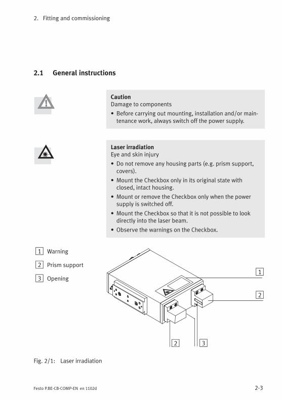
CautionDamage to components
• Before carrying out mounting, installation and/or main-tenance work, always switch off the power supply.
Laser irradiationEye and skin injury
• Do not remove any housing parts (e.g. prism support,covers).
• Mount the Checkbox only in its original state withclosed, intact housing.
• Mount or remove the Checkbox only when the powersupply is switched off.
• Mount the Checkbox so that it is not possible to lookdirectly into the laser beam.
• Observe the warnings on the Checkbox.
1 Warning
2 Prism support
3 Opening1
2
32
Fig. 2/1: Laser irradiation

2. Fitting and commissioning
2-4 Festo P.BE-CB-COMP-EN en 1102d
2.2 Mounting
Transport Always transport the Checkbox in its original packing; furthertransport safety devices are not necessary.
Mounting location Observe especially the following conditions:
– the mounting location must be free of vibration
– there must be stable mechanical fastening
– the ambient air must be clean: free of oil, no paint spray,no grinding dust
– Screening of external light influences and extrememagnetic fields (e.g. due to induction furnaces).
In this way you will achieve optimum test results and ensurea long service life of the device.
Conveyor device In order that the test results can be reliable and reproducible,the conveyor device used should fulfill the following require-ments:
� Use a high-grade transporting system which conveys theparts at a constant speed.
� Ensure the stable position of the parts, e.g. by means ofmechanical devices.
� Use also mechanical devices to secure the parts transferfrom the conveyor device to the buffer zone (e.g. droppipe, slide, waste) of the subsequent machine.
Space requirement Note the space required for mounting the Checkbox. Thedimensions of the Checkbox and specifications on weight canbe found in the Appendix A.5.
Fastening On the side of the Checkbox there is a mounting profile withdovetail guide.

2. Fitting and commissioning
2-5Festo P.BE-CB-COMP-EN en 1102d
A connecting kit (type HMSV-12) is available as an accessoryfrom Festo.
1 Mounting profileof the Checkbox
2 Clampingelements with4 M5x45 sockethead screws
3 2 M5x16 sockethead screws withcentring sleeves
4 Adapter plate
1
2
3
4
Fig. 2/2: Fastening the Checkbox with connecting kit type HMSV-12
Fasten the Checkbox over the conveyor device so that:
– the warning sign on the device is still visible (Fig. 2/1 )
– the Checkbox and the conveyor device are fastened stablyto each other (Fig. 2/3)
– the viewing range of the camera is not impeded
– the optical channel is not covered by the conveyor device.
2. Fitting and commissioning
2-6 Festo P.BE-CB-COMP-EN en 1102d
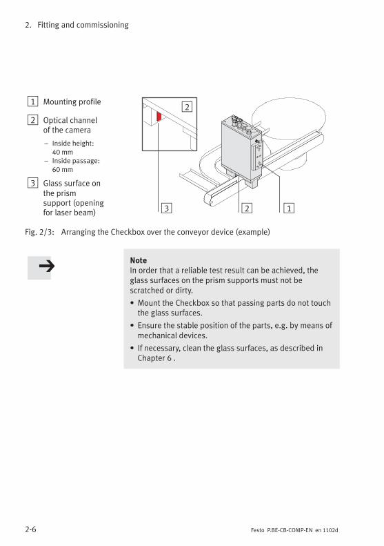
1 Mounting profile
2 Optical channelof the camera
– Inside height:40 mm
– Inside passage:60 mm
3 Glass surface onthe prismsupport (openingfor laser beam) 13 2
2
Fig. 2/3: Arranging the Checkbox over the conveyor device (example)
NoteIn order that a reliable test result can be achieved, theglass surfaces on the prism supports must not bescratched or dirty.
• Mount the Checkbox so that passing parts do not touchthe glass surfaces.
• Ensure the stable position of the parts, e.g. by means ofmechanical devices.
• If necessary, clean the glass surfaces, as described inChapter 6 .
2. Fitting and commissioning
2-7Festo P.BE-CB-COMP-EN en 1102d
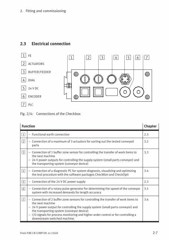
2.3 Electrical connection
1 FE
2 ACTUATORS
3 BUFFER/FEEDER
4 DIAG
5 24 V DC
6 ENCODER
7 PLC
1 2 3 4 5 6 7
Fig. 2/4: Connections of the Checkbox
Function Chapter
1 – Functional earth connection 2.3
2 – Connection of a maximum of 3 actuators for sorting out the tested conveyedparts
3.2
3 – Connection of 1 buffer zone sensor for controlling the transfer of work items tothe next machine
– 24 V power outputs for controlling the supply system (small parts conveyor) andthe transporting system (conveyor device)
3.3
4 – Connection of a diagnostic PC for system diagnosis, visualizing and optimizingthe test procedure with the software packages CheckKon and CheckOpti
3.4
5 – Connection of the 24 V DC power supply 2.3
6 – Connection of a rotary pulse generator for determining the speed of the conveyorsystem with increased demands for length accuracy
3.5
7 – Connection of 2 buffer zone sensors for controlling the transfer of work items tothe next machine
– 24 V power output for controlling the supply system (small parts conveyor) andthe transporting system (conveyor device)
– I/O signals for process monitoring and higher-order control or for controlling adownstream-switched machine.
3.6

2. Fitting and commissioning
2-8 Festo P.BE-CB-COMP-EN en 1102d
Caution• Check within the framework of your EMERGENCY STOPconcept to ascertain the measures necessary for puttingyour machine/system into a safe state in the event of anEMERGENCY STOP (e.g. switching off the operatingvoltage, switching off pressure).
Preparing plugs and cables
Use plugs and sockets from the Festo supply programmewhich match the outer diameter of the cables used(www.festo.com/catalogue).
NoteIn this way, you will avoid interference from electromag-netic influences:
• Use only screened cable.
• Use large-cross-section cable that is as short as possible.
• Connect both the FE earth terminal and the cablescreening with low impedance to the earth potential.
Cable outside diameter Plugs/sockets
4.0 ... 6.0 mm PG 7
6.0 ... 8.0 mm PG 9
10.0 ... 12.0 mm PG 13.5
Tab. 2/1: Cable outside diameter

2. Fitting and commissioning
2-9Festo P.BE-CB-COMP-EN en 1102d
Connection Plugs/sockets
Power supply socket PG 9 or PG 13.5
Sensors, actuators PG 7
Tab. 2/2: Connection
In order to guarantee observance of the IP protection classfor the completely fitted Checkbox:
� tighten the union nuts of the plugs by hand
� seal unused sockets with the protective caps supplied.
CautionLong I/O signal lines reduce the resistance to interference.
• Comply with the maximum permissible I/O signal linelength of 30 m.

2. Fitting and commissioning
2-10 Festo P.BE-CB-COMP-EN en 1102d
2.3.1 Selection of the power supply unit
The power supply for the Checkbox must fulfill the followingrequirements:
– voltage range: 24 V ± 15 %
– Power rating: 18 W with load-free outputs
– no current consumption at the outputs
In order to comply with the EMC limits, the Checkbox isequipped with a filter for the operating voltage. Use aseparate power unit for the Checkbox. Only in this way canthe fitted filter be effective.
Warning• Use only power sources which guarantee reliableelectrical isolation of the operating voltage as perIEC/EN 60204-1. Observe also the general requirementsfor PELV power circuits as per IEC/EN 60204-1.

2. Fitting and commissioning
2-11Festo P.BE-CB-COMP-EN en 1102d
2.3.2 Connection of the operating voltage
� Use an operating voltage cable with sufficientcross-sectional area.
� Avoid long distances between the power supply unit andthe Checkbox. Long operating voltage cables reduce thevoltage supplied by the power unit.
� Protect the supply cable with a 5 A cut-out fuse with me-dium time-lag.
Connect the Checkbox to the operating voltage as follows:
Pin 24 V DC plug
1 Do not connect
2 +24 V DC, +/- 15 %with 5 A medium time-lag fuse
3 GND
4 Do not connect
Tab. 2/3: 24 V DC connection plug
Use only a 4-pin M18 socket for the power supply andconnect this only to the connection for the power supply.
1. Connect the plug to the 24 V DC connection on theCheckbox.
2. Tighten the union nuts of the plug by hand.
2. Fitting and commissioning
2-12 Festo P.BE-CB-COMP-EN en 1102d
2.3.3 Power supply for external components
If you connect the Checkbox via the connections PLC,ACTUATOR or BUFFER/FEEDER with other devices(e.g. PLC, conveyor device), observe the following:
NoteIn order to comply with the EMC limits, the Checkbox isequipped with a filter for the operating voltage.
A connection between the 24 V potential and GND at the24 V DC plug with other plugs on the Checkbox or withother devices will in some cases bridge the installed filter.Asymmetries of the currents in the outgoing and returnlines will reduce the effect of the filter.
� Use a separate power unit for the Checkbox. Provide aseparate power supply for connected current-consumingdevices.
� Do not connect the 24 V potential and GND at the“24 V DC” connection of the Checkbox with other plugsof the Checkbox or with other devices.
� Make sure that the currents of the inputs and outputsflow via the Checkbox and not directly to the power unit.
Consuming devices can also be supplied with voltage via thePLC plug. Observe also the information in Chapter 3.6.

2. Fitting and commissioning
2-13Festo P.BE-CB-COMP-EN en 1102d
2.4 Adapting system parameters with CheckKon
A password is required for CheckKon for setting the systemparameters and transmitting the modifications to theCheckbox (Function “Modify system”). You can obtain yourpassword via the service hotline +49 / 711 / 347-1610. Thefunction “Observe system” can be used without a password.
1. Install CheckKon on your diagnostic PC. Notes oninstallation can be found in the software manual.
2. Connect the Checkbox at the DIAG connection with thediagnostic PC (see Chapter 3.4). Connect the devices onlywhen the power supplies are switched off.
Diagnostic mode Start CheckKon when the Checkbox has been switched on.When Checkkon is started, it carries out a system test andswitches the Checkbox to the diagnostic mode.
NoteIn diagnostic mode the Checkbox transmits additionalinformation via the diagnostic interface. During thetransmission time no parts are checked.
• Do not operate the Checkbox in diagnostic mode withthe full rate of parts.
In this way you can prevent parts from passing theactuator positions unchecked.
1. Adapt the Checkbox to your system requirements withthe system parameters in the menu [Window] [Systemparameters]. Note also the instructions in the followingchapters and in the software manual.

2. Fitting and commissioning
2-14 Festo P.BE-CB-COMP-EN en 1102d
CheckKon shows the most important system parametersthrough the menu [Window] [System parameters] symbol“Only important parameters”. Make sure that these para-meters are adapted to your application.
2. Transfer the modified settings to the Checkbox(see software manual).
3. Conclude CheckKon and with it the diagnostic mode whenall settings have been completed.
NoteFaulty processing data can cause incorrect functioning ofthe Checkbox.
• Carry out the complete Teach procedure again if youhave modified the system parameters with CheckKon.

2. Fitting and commissioning
2-15Festo P.BE-CB-COMP-EN en 1102d
2.5 Commissioning the Checkbox
1 Illuminatedpush-buttonSTART/STOP
2 Illuminatedpush-buttonSTATUS/TEACH
3 Display
2 31
Fig. 2/5: Display and operating elements
Function
1 – Starting and stopping the Checkbox– Display of the switching function Start (green)/Stop (red)– Acknowledging errors– Saving the Teach data
2 – Switch between AUTO and TEACH modes– Selecting the orientation in the TEACH mode– Displaying the scan procedure– Accessing system information (e.g. belt speed during
operation with encoder)
3 – System information and operating displays

2. Fitting and commissioning
2-16 Festo P.BE-CB-COMP-EN en 1102d
Before the Checkbox is switched on the first time, make surethat you have completed the following steps:
1. mounting of the conveyor device
2. mounting of the Checkbox to the conveyor device
3. connection of operating voltage to the 24 V DC connection
4. connection of external components, if requiredObserve the instructions on connecting externalcomponents in the following chapters:
– Chapter 3.2 “Actuators”
– Chapter 3.3 “Buffer zone sensors, small partsconveyor”
– Chapter 3.5 “Encoder”
– Chapter 3.6 “Higher-order controller”
WarningCheck to see which measures are necessary for puttingyour machine/system in a safe state when it is switched onand off. Observe that movements of the connected actuat-ors can cause injury to people and damage to property, forexample
• when the conveyor device is moved to its basic positionwhen the power supply is switched off
• the conveyor device starts automatically if controlled bythe Checkbox when the Checkbox starts.
In order to prevent the conveyor device from starting auto-matically when the operating voltage is switched on:
• Select in CheckKon [Window] [System parameters]�System� Operating modes ...� Automatic start afterpower supply on = no (factory setting).

2. Fitting and commissioning
2-17Festo P.BE-CB-COMP-EN en 1102d
Switching on • Switch on the operating voltage for the Checkbox via thepower unit.
• Start CheckKon in order to display and set the systemparameters during the TEACH and test modes(see Chapter 2.4).
• Start the conveyor device, if necessary manually.
The illuminated buttons on the Checkbox light up briefly andsignal the readiness to operate. The display shows briefly thefollowing items of system information one after the other:
LED Explanation
CC 30 Ident. code and version status of the operating system
04 E 1) Numberofmemory locationsandadditionally the letter Ewith operating systems with encoder evaluation
2048 System setting of the camera resolution in pixels
Stop Ready to operate (AUTO mode: stop status)
1) For evaluation of the encoder signals, the operating systemversion ...E must be used. Consult your Festo Service if you wishto modify your operating system.
Tab. 2/4: Operating display when switched on
LockIf “Lock” is shown in the display, the buttons START/STOPand STATUS/TEACH are locked (see Chapter 3.6.8).
2. Fitting and commissioning
2-18 Festo P.BE-CB-COMP-EN en 1102d
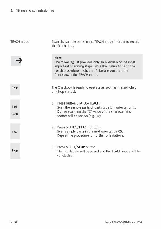
TEACH mode Scan the sample parts in the TEACH mode in order to recordthe Teach data.
NoteThe following list provides only an overview of the mostimportant operating steps. Note the instructions on theTeach procedure in Chapter 4, before you start theCheckbox in the TEACH mode.
Stop The Checkbox is ready to operate as soon as it is switchedon (Stop status).
1 o1
C 30
1. Press button STATUS/TEACH.Scan the sample parts of parts type 1 in orientation 1.During scanning the “C” value of the characteristicscatter will be shown (e.g. 30)
1 o2
2. Press STATUS/TEACH button.Scan sample parts in the next orientation (2).Repeat the procedure for further orientations.
Stop3. Press START/STOP button.
The Teach data will be saved and the TEACH mode will beconcluded.

2. Fitting and commissioning
2-19Festo P.BE-CB-COMP-EN en 1102d
AUTO mode Evaluate the reliability of the Teach data before you beginwith the automatic parts test.
NoteThe following list provides only an overview of the mostimportant operating steps.
• Note the instructions on the test procedure in Chapter 5,before you start the Checkbox in the AUTO mode.
Stop The Checkbox is ready to operate (Stop status).
1 5
A...
#...
1. Press START/STOP button.Presetting: Parts type 1; tolerance 5 % (influence andsetting tolerance, see Chapter 5.3)
2. Check the inspection part deviation “A” and the inspec-tion part orientation “#” (see Chapter 5.4).
3. If necessary, correct the system settings with CheckKon.
NoteFaulty processing data can cause incorrect functioning ofthe Checkbox.
• Carry out the complete Teach procedure again if youhave modified the system parameters with CheckKon.
4. Conclude CheckKon when all the settings have been com-pleted.
Switching off Switch the Checkbox to the Stop status before switching it off.
Stop 1. Press START/STOP button.
2. Switch off the operating voltage.
2. Fitting and commissioning
2-20 Festo P.BE-CB-COMP-EN en 1102d
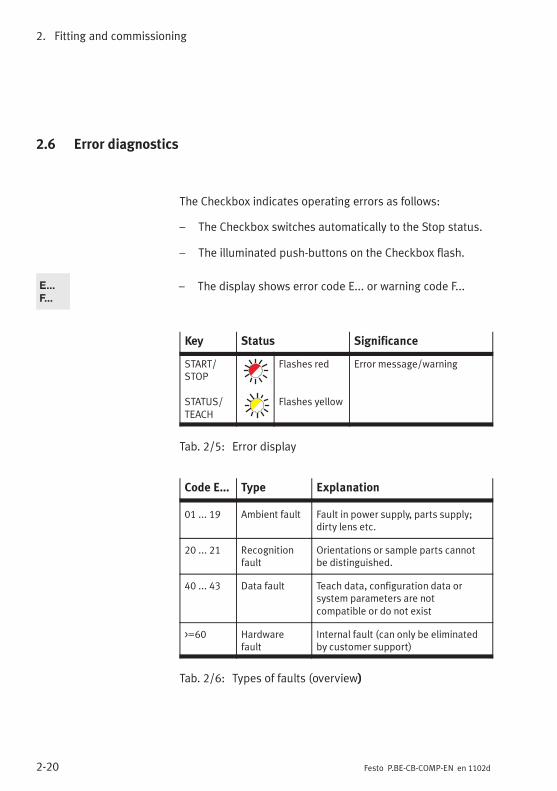
2.6 Error diagnostics
The Checkbox indicates operating errors as follows:
– The Checkbox switches automatically to the Stop status.
– The illuminated push-buttons on the Checkbox flash.
E...
F...– The display shows error code E... or warning code F...
Key Status Significance
START/STOP
STATUS/TEACH
Flashes red
Flashes yellow
Error message/warning
Tab. 2/5: Error display
Code E... Type Explanation
01 ... 19 Ambient fault Fault in power supply, parts supply;dirty lens etc.
20 ... 21 Recognitionfault
Orientations or sample parts cannotbe distinguished.
40 ... 43 Data fault Teach data, configuration data orsystem parameters are notcompatible or do not exist
>=60 Hardwarefault
Internal fault (can only be eliminatedby customer support)
Tab. 2/6: Types of faults (overview)

2. Fitting and commissioning
2-21Festo P.BE-CB-COMP-EN en 1102d
The Checkbox cannot be started again until the fault has beeneliminated:
1. Eliminate cause of malfunction
2. Acknowledge the fault signals: Press the START/STOPbutton
3. Start the Checkbox: Press the START/STOP button
Further information:
– Details on the fault codes and instructions on eliminatingfaults can be found in Appendix A.1.
– The CHB-C-X signals faults also at the PLC connection viaO/17 (fault) and O/23 (warning) (see Chapter 3.6.7).

2. Fitting and commissioning
2-22 Festo P.BE-CB-COMP-EN en 1102d

The I/O module
3-1Festo P.BE-CB-COMP-EN en 1102d
The I/O module
Chapter 3

3. The I/O module
3-2 Festo P.BE-CB-COMP-EN en 1102d
Contents
3. The I/O module 3-1. . . . . . . . . . . . . . . . . . . . . . . . . . . . . . . . . . . . . . . . . . . . . . . .
3.1 Interfaces 3-3. . . . . . . . . . . . . . . . . . . . . . . . . . . . . . . . . . . . . . . . . . . . . . . . . . . . .
3.2 ACTUATORS 3-5. . . . . . . . . . . . . . . . . . . . . . . . . . . . . . . . . . . . . . . . . . . . . . . . . . .
3.3 BUFFER/FEEDER 3-7. . . . . . . . . . . . . . . . . . . . . . . . . . . . . . . . . . . . . . . . . . . . . . .
3.4 DIAG 3-10. . . . . . . . . . . . . . . . . . . . . . . . . . . . . . . . . . . . . . . . . . . . . . . . . . . . . . . . .
3.5 ENCODER 3-12. . . . . . . . . . . . . . . . . . . . . . . . . . . . . . . . . . . . . . . . . . . . . . . . . . . . .
3.6 PLC 3-14. . . . . . . . . . . . . . . . . . . . . . . . . . . . . . . . . . . . . . . . . . . . . . . . . . . . . . . . . . .
3.6.1 Start/Stop mode 3-17. . . . . . . . . . . . . . . . . . . . . . . . . . . . . . . . . . . . . . . .
3.6.2 Controlling the teach procedure 3-19. . . . . . . . . . . . . . . . . . . . . . . . . . . .
3.6.3 Selecting the parts type 3-19. . . . . . . . . . . . . . . . . . . . . . . . . . . . . . . . . .
3.6.4 Counting function 3-23. . . . . . . . . . . . . . . . . . . . . . . . . . . . . . . . . . . . . . .
3.6.5 Actuators 3-26. . . . . . . . . . . . . . . . . . . . . . . . . . . . . . . . . . . . . . . . . . . . . .
3.6.6 Buffer zone sensors/small parts conveyor 3-27. . . . . . . . . . . . . . . . . . .
3.6.7 Fault messages 3-30. . . . . . . . . . . . . . . . . . . . . . . . . . . . . . . . . . . . . . . . .
3.6.8 Locking the control panel 3-31. . . . . . . . . . . . . . . . . . . . . . . . . . . . . . . . .
3. The I/O module
3-3Festo P.BE-CB-COMP-EN en 1102d
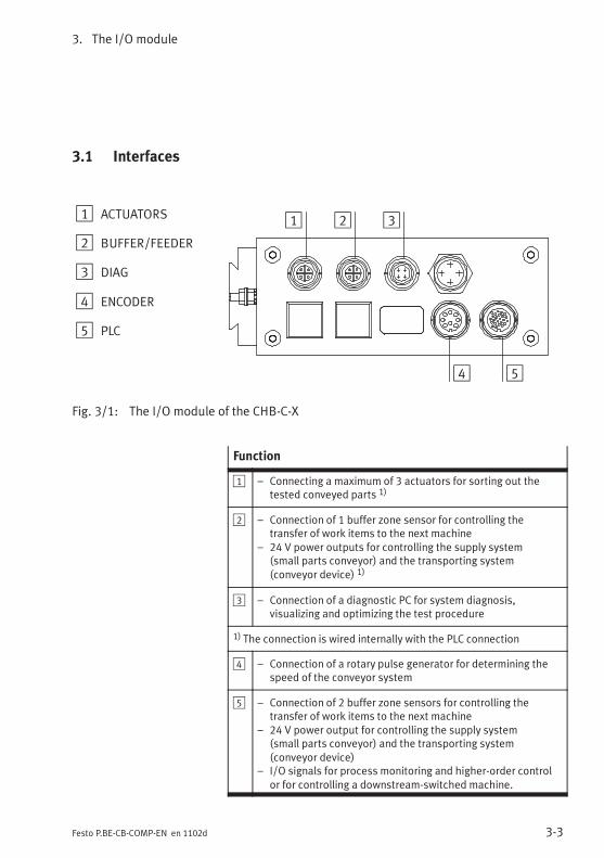
3.1 Interfaces
1 ACTUATORS
2 BUFFER/FEEDER
3 DIAG
4 ENCODER
5 PLC
4 5
1 2 3
Fig. 3/1: The I/O module of the CHB-C-X
Function
1 – Connecting a maximum of 3 actuators for sorting out thetested conveyed parts 1)
2 – Connection of 1 buffer zone sensor for controlling thetransfer of work items to the next machine
– 24 V power outputs for controlling the supply system(small parts conveyor) and the transporting system(conveyor device) 1)
3 – Connection of a diagnostic PC for system diagnosis,visualizing and optimizing the test procedure
1) The connection is wired internally with the PLC connection
4 – Connection of a rotary pulse generator for determining thespeed of the conveyor system
5 – Connection of 2 buffer zone sensors for controlling thetransfer of work items to the next machine
– 24 V power output for controlling the supply system(small parts conveyor) and the transporting system(conveyor device)
– I/O signals for process monitoring and higher-order controlor for controlling a downstream-switched machine.

3. The I/O module
3-4 Festo P.BE-CB-COMP-EN en 1102d
Power supply Observe the instructions on supplying power to external com-ponents in Chapter 2.3.3 and Chapter 3.6.
Electrical properties of the I/O signals
Outputs – Max. current loading per channel: 700 mA– Max. sum current of all outputs:
ACTUATORS 2.1 ABUFFER 1.4 A
– Positive switching
Inputs – Input current: . 30 mA– Logical “1”: Von , 15 V– Logical “0”: Von . 5 V
Tab. 3/1: Electrical properties of the I/O signals
3. The I/O module
3-5Festo P.BE-CB-COMP-EN en 1102d
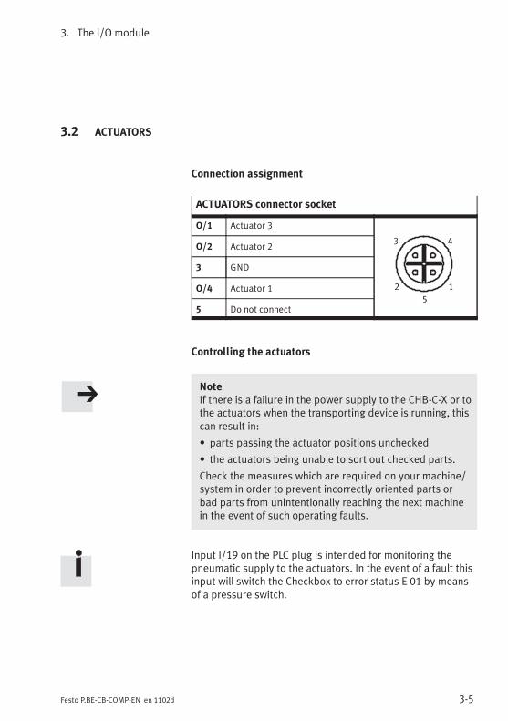
3.2 ACTUATORS
Connection assignment
ACTUATORS connector socket
O/1 Actuator 3
1
43
2
5
O/2 Actuator 2
3 GND
O/4 Actuator 1
5 Do not connect
Controlling the actuators
NoteIf there is a failure in the power supply to the CHB-C-X or tothe actuators when the transporting device is running, thiscan result in:
• parts passing the actuator positions unchecked
• the actuators being unable to sort out checked parts.
Check the measures which are required on your machine/system in order to prevent incorrectly oriented parts orbad parts from unintentionally reaching the next machinein the event of such operating faults.
Input I/19 on the PLC plug is intended for monitoring thepneumatic supply to the actuators. In the event of a fault thisinput will switch the Checkbox to error status E 01 by meansof a pressure switch.

3. The I/O module
3-6 Festo P.BE-CB-COMP-EN en 1102d
The CHB-C-X can control up to 3 actuators for sorting outgood parts, incorrectly oriented parts and bad parts. Possibleactuators are e.g. shunts, reversing stations or air nozzleswhich sort out the parts at certain positions on thetransporting device depending on the test result. The numberand assignment of the actuator positions may vary dependingon application. The assignment of the actuator positions canbe adapted with the CheckKon software.
Example of configuration Transporting device with 2 blow-out nozzles (see Fig. 1/1)
The compressed air valves of the blow-out positions must beconnected directly with the outputs for actuators 1 ... 2.These outputs are set to +24 V DC if the parts test providesthe following result:
– incorrectly oriented or superfluous (good) part
– bad or foreign part
If the CHB-C-X recognizes an inspection part as good,the signal actuator 3 will be set from the rest potential0 V to +24 V DC and the good part will be output at the end ofthe transporting device.
Output Signal level 1) (example of configuration)
Actuator 1 There is a +24 V DC signal when the inspectionpart passes the actuator position for incorrectlyoriented or superfluous good parts.
Actuator 2 There is a +24 V DC signal when the inspectionpart passes the actuator position for bad orforeign parts.
Actuator 3 There is a +24 V DC signal when the inspectionpart passes the actuator position for good parts(here: the end of the transporting device).
1) The duration of the signal corresponds to the time required forthe part to reach the air jet nozzle.

3. The I/O module
3-7Festo P.BE-CB-COMP-EN en 1102d
3.3 BUFFER/FEEDER
Connection assignment
BUFFER/FEEDER connector socket
O/1 24 V DC/Box ready– Reference voltage for sensors
(switched off in Stop status)– Ready status– Control for transporting device
1
43
2
5
O/2 FeederControlling the supply system(small parts conveyor)
3 GNDReference voltage for sensors
I/4 BufferBuffer zone sensor 1
5 Do not connect
Direct connection can optionally be made with a Festo Duocable (see Accessories, Appendix A.6).
Identifying the Duo cable
Signal x Buffer zone sensor 1
Signal x + 1 Small parts conveyor (feeder)
Controlling the small parts conveyor (feeder)
If it is possible to connect an external enable signal (24 V DC)to the small parts conveyor, connect this signal via pin O/2 onthe BUFFER/FEEDER plug.

3. The I/O module
3-8 Festo P.BE-CB-COMP-EN en 1102d
Controlling the buffer zone sensor (buffer)
NoteOnly in this way is the Checkbox ready to operate:
• Leave non-used sensor inputs open.
Otherwise the display will show the operating status “Full”,although the buffer zone is free. All good parts will be re-turned. The small parts conveyor will be switched off after30 s (standard setting).
Signal duration In order to avoid unnecessary switching movements, theCheckbox reacts only after a certain signal duration to thesensor signals for “Buffer zone full” and “Buffer zone empty”.
Modification of the signal duration with CheckKon in the menu[Window] [System parameters]� System� Transportingsystems� Continuing systems ...� Minimum sensor signalduration for status:buffer zone full: 1.0 s (0.1 s ... 180 s)buffer zone empty: 1.0 s (0.1 s ... 180 s)
Sensor type The CHB-C-X is set at the factory for use with a buffer zonesensor, the sensor output of which lies at a potential of 0 V(negative switching) in the rest state.
Modification of the sensor type with CheckKon in the menu[Window] [System parameters]:� System� Transportingsystems� Continuing systems ...� Buffer zone sensor types= positive switching.

3. The I/O module
3-9Festo P.BE-CB-COMP-EN en 1102d
NoteYou can optimize the operational safety of your supplysystem as follows:
• Use sensors which have a sensor output with a potentialof 24 V DC in the rest state.
• Adapt the setting of the sensor type with CheckKon.
You can then prevent the system from becoming blockede.g. in the event of a broken cable.
Sensor type FunctionBuffer zone with one sensor
Normallyopencontact 1)
Normallyclosedcontact 2)
Sensor 1LOW
Sensor 1HIGH
The sensor does not register aconveyed part. The small partsconveyor is/remains switched on.
Sensor 1HIGH
Sensor 1LOW
The buffer zone is full. The displayswitches to “Full”. Good parts arereturned. When the preset timee.g. 30 s has expired, the smallparts conveyor will be switchedoff; the conveyor device contin-ues to run.
1) Factory presetting; negative switching (NPN), 24 V DC active high2) To be set with CheckKon (recommendation); positive switching
(PNP), 24 V DC active low
Information on dimensioning the buffer zone can be found inChapter 1.5.

3. The I/O module
3-10 Festo P.BE-CB-COMP-EN en 1102d
3.4 DIAG
NoteIn the diagnostic mode the CHB-C-X transmits additionalinformation via the diagnostic interface. During the trans-mission time no parts are checked.
• Use the DIAG connection only for commissioning and forservicing.
• Do not operate the CHB-C-X in the diagnostic mode withthe full parts rate. In this way you can prevent partsfrom passing the actuator positions unchecked.
In order to connect a diagnostic PC use cable KDI-SB202-BU9(see Appendix A.6 Accessories).
1. Connect the diagnostic cable to the following connections:
– the diagnostic interface DIAG on the CHB-C-X
– a serial interface (COM) of the diagnostic PC
DIAG connector socket
I/1 Received data
1
4 3
2
O/2 Transmitted data
3 Data GND
4 Screened
2. Start CheckKon or CheckOpti in order to display thesystem data and to set the system parameters in theTeach or test modes.
3. Conclude CheckKon and CheckOpti when you haveundertaken the necessary settings.

3. The I/O module
3-11Festo P.BE-CB-COMP-EN en 1102d
4. Remove the diagnostic cable from the DIAG connection incontinuous operation. Seal the connection with theprotective cap supplied.
Further information on commissioning, optimizing andmonitoring the Checkbox via the diagnostic interface can befound in the documentation for the CheckKon and CheckOptisoftware packages.

3. The I/O module
3-12 Festo P.BE-CB-COMP-EN en 1102d
3.5 ENCODER
If high demands are placed on the accuracy of the length ofthe test part, you can connect a rotary pulse generator to theENCODER connection for determining the speed of the con-veyor system (see Accessories, Appendix A.6).
Pin ENCODER connector socket
Interface for rotary pulse generatoras per RS 485 specification
1
2
3
4 5
6 7
8
1 A+
2 n.c.
3 B+
4 A-
5 B-
6 5 V supply 1)
7 GND
8 n.c.
1)Maximum loading 180 mA
Tab. 3/2: ENCODER connector socket
NoteObserve the following when connecting a rotary pulsegenerator:
• Do not connect the potentials of the ENCODER connec-tion with other potentials.
• Use only suitable rotary pulse generators, e.g. encodersfrom the Festo product range.

3. The I/O module
3-13Festo P.BE-CB-COMP-EN en 1102d
Evaluation of the encoder signals
� Check the operating system version when you switchon your CHB-C-X (see Chapter 2.5, Commissioning:Switching on).
Note• Use the operating system version ...E to evaluate theencoder signals.
• Consult your Festo Service if you wish to modify youroperating system.
Display of the belt speed
� Press the button STATUS/TEACH in AUTO mode.
The display will then show the belt speed of the conveyor unitin [mm/s].

3. The I/O module
3-14 Festo P.BE-CB-COMP-EN en 1102d
3.6 PLC
Observe the following when connecting a higher-order con-troller:
� Use the PLC cable with 24-pin Binder plug supplied.
� Connect the cables of the PLC according to the cableassignment in Appendix A.4.
� Make sure that the maximum sum current of 1 A at thePLC connection is not exceeded.
Reference voltage The reference voltage is available at pin 4 (GND) and pin O/7(+24 V). Fuse: 700 mA, automatic reset.
Pin Reference voltage
4 0 Ve.g. as reference potential for the PLC/reference voltage forbuffer zone sensors
O/7 +24 V DCe.g. as voltage supply for opto-isolated PLC I/O module,signal level after boot procedure = HIGH
Tab. 3/3: Reference voltage
Load voltage Consuming devices can be supplied with power via pin 4(GND) and pin O/7 (+24 V) under the following conditions:
� Connect only consuming devices which return the com-plete current to the CHB-C-X. In this way you can preventasymmetries of the currents in the outgoing and returnlines from reducing the effect of the filter.
� Load output O/7 with maximum 700 mA.

3. The I/O module
3-15Festo P.BE-CB-COMP-EN en 1102d
I/O functions of the PLC interface Pin
Remote Start Start/stop mode I/6
Selecting the parts type External type selection: Bit 0 I/20
External type selection: Bit 1 I/5
External type selection: Bit 2 I/13
External type selection: Bit 3 I/10
Controlling the teach procedure1) Selecting the teach mode andthe next orientation
I/15
Saving teach data I/6
Locking the control panel Key lock I/11
Counting function 2) Start new counting cycle I/18
Target number reached O/22
Controlling the transfer position for:– Good parts Actuator 1 O/1
– Incorrectly orientated good parts orIncorrect parts type
Actuator 2 O/2
– Bad/foreign parts Actuator 3 O/3
Controlling the parts supply Buffer zone sensor 1 I/12
Controlling the small parts conveyor O/8
Readiness to operate, controlling the conveyordevice
O/21
Error messages Fault status 1: Status signal “Fault” O/17
1)User-specific function. Consult your Festo Service if you have any problems.2) Counter function and special function “External sensor” cannot be used at the same time.
Tab. 3/4: I/O functions of the PLC interface
3. The I/O module
3-16 Festo P.BE-CB-COMP-EN en 1102d
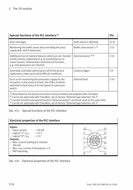
Special functions of the PLC interface 1) Pin
Error messages Fault status 0: Warning O/23
Monitoring the buffer zones and controlling the partssupply with switch hysteresis
Buffer zone sensor 2 2) I/13
Additional test of material features which are not checkedduring contour registering (e.g. by metal detector orcolour sensor). Downstream-switched test function,e.g. only good parts are checked.
External sensor 3) 4) I/10
Externally controlled switching on/off of the pictureregistration under particularly difficult conditions.
Camera trigger I/9
Such as for monitoring the pneumatic supply for theactuators: In the event of a fault, the CHB-C-X will beswitched to fault status E 01 by means of a pressureswitch.
External fault I/19
1) Deactivated at the factory Functions can be activated and adapted with CheckKon.2) Can be set optionally with CheckKon, set at factory “External type selection: bit 2”.3) Counter function and special function “External sensor” cannot be used at the same time.4) Can be set optionally with CheckKon, set at factory “External type selection: bit 3”.
Tab. 3/5: Special functions of the PLC interface
Electrical properties of the PLC interface
Inputs:– Input current: . 30 mA– Logical “1”: Von , 15 V– Logical “0”: Von . 5 VOutputs:– Max. current loading per channel:
700 mA– Max. sum current of all outputs: 1 A– PNP switching
1
3
7
4
8
12 13
16
21
17
22
24
Tab. 3/6: Electrical properties of the PLC interface

3. The I/O module
3-17Festo P.BE-CB-COMP-EN en 1102d
3.6.1 Start/Stop mode
The controller of the CHB-C-X assumes that:
– the power supply for the CHB-C-X is applied
– the boot procedure has been completed (O/7 = HIGH)
– the signals for selecting the parts type are applied(see Chapter 3.6.3).
The Checkbox is started with a signal sequence (pulse) atpin I/6 LOW> HIGH> LOW and is stopped again with thesignal sequence LOW> HIGH> LOW (recommended pulseduration 500 ms).
Pin Signal sequence Significance
I/6 LOW> HIGH> LOW Starts the Checkbox
LOW> HIGH> LOW Stops the Checkbox
Tab. 3/7: Signal sequence with Start/Stop mode
With varying manual operation or control via the I/O module,pressing the START/STOP button corresponds to the signalchange LOW> HIGH> LOW.
The modification of the operating status with Start or Stop issent to the controller via O/21.

3. The I/O module
3-18 Festo P.BE-CB-COMP-EN en 1102d
Pulse-time diagramTiming requirement to the higher-order controller
24 VPower supply
Pin O/7PLC_Power
Pin I/20 20
Type selectPin I/5 21
Type select
Pin I/6Ext_Start
Pin O/8Feeder
Pin O/21Box_Ready
t ts
t rs
t d
Start Stop
0
1
0
1
0
1
0
1
0
1
0
1
t rs
Type 2 Type 3
0.2 s . t rs . 1 s rs = remote startt ts =min 0.1 s ts = type selectt d = duration of the switch-on delay d = delay
Tab. 3/8: Pulse-time diagram: Timing requirement to the higher-order controller
3. The I/O module
3-19Festo P.BE-CB-COMP-EN en 1102d
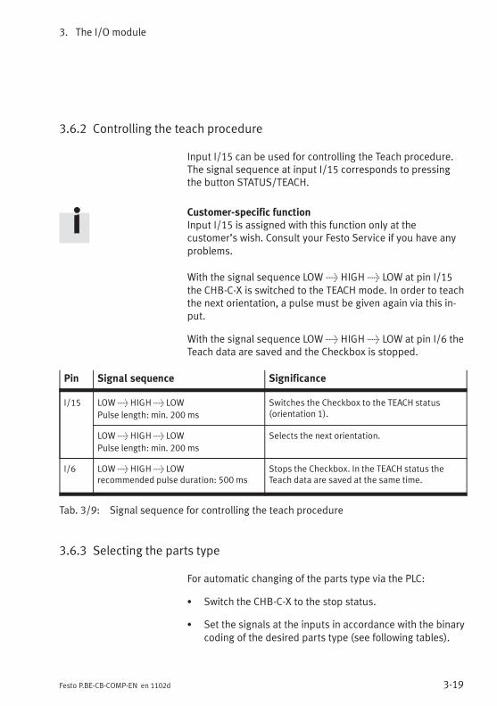
3.6.2 Controlling the teach procedure
Input I/15 can be used for controlling the Teach procedure.The signal sequence at input I/15 corresponds to pressingthe button STATUS/TEACH.
Customer-specific functionInput I/15 is assigned with this function only at thecustomer’s wish. Consult your Festo Service if you have anyproblems.
With the signal sequence LOW> HIGH> LOW at pin I/15the CHB-C-X is switched to the TEACH mode. In order to teachthe next orientation, a pulse must be given again via this in-put.
With the signal sequence LOW> HIGH> LOW at pin I/6 theTeach data are saved and the Checkbox is stopped.
Pin Signal sequence Significance
I/15 LOW> HIGH> LOW
Pulse length: min. 200 ms
Switches the Checkbox to the TEACH status(orientation 1).
LOW> HIGH> LOW
Pulse length: min. 200 ms
Selects the next orientation.
I/6 LOW> HIGH> LOWrecommended pulse duration: 500 ms
Stops the Checkbox. In the TEACH status theTeach data are saved at the same time.
Tab. 3/9: Signal sequence for controlling the teach procedure
3.6.3 Selecting the parts type
For automatic changing of the parts type via the PLC:
� Switch the CHB-C-X to the stop status.
� Set the signals at the inputs in accordance with the binarycoding of the desired parts type (see following tables).

3. The I/O module
3-20 Festo P.BE-CB-COMP-EN en 1102d
Maximum 4 parts types can be addressed via the inputs I/20and I/5. The signals must be applied permanently before theCHB-C-X starts again.
tool If the information “tool” is shown in the display when theparts type is selected, the memory address will be occupiedwith additional software tools. However, the teach procedurecan still be carried out. Further information: in the CheckOptimanual.
Binary codingParts types 1 ... 4
I/202 0
I/52 1
1 LOW LOW
2 HIGH LOW
3 LOW HIGH
4 HIGH HIGH
Tab. 3/10: Binary coding parts type 1 ... 4
Pulse-time diagram (with max. 4 parts types)Parts type change 1> 4
Pin I/20Type select 0
Pin I/5Type select 1
Pin I/6Remote start
0
1
0
1
0
1
min 0.1 s
Type 1 Type 4
Tab. 3/11: Pulse-time diagram: Parts type change 1} 4
3. The I/O module
3-21Festo P.BE-CB-COMP-EN en 1102d
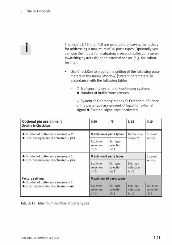
The inputs I/13 and I/10 are used before leaving the factoryfor addressing a maximum of 16 parts types. Optionally youcan use the inputs for evaluating a second buffer zone sensor(switching hysteresis) or an external sensor (e.g. for colourtesting).
� Use CheckKon to modify the setting of the following para-meters in the menu [Window] [System parameters] inaccordance with the following table:
– � Transporting systems� Continuing systems� Number of buffer zone sensors
– � System� Operating modes� Extended influenceof the parts type assignment� Input for externalsignal� External signal input activated
Optional pin assignmentSetting in CheckKon
I/20 I/5 I/13 I/10
� Number of buffer zone sensors = 2� External signal input activated = yes
Maximum 4 parts types Buffer zone
sensor 2
External
sensorExt. type
selection
bit 0
Ext. type
selection
bit 1
� Number of buffer zone sensors = 1� External signal input activated = yes
Maximum 8 parts types External
sensorExt. type
selection
bit 0
Ext. type
selection
bit 1
Ext. type
selection
bit 2
Factory setting:� Number of buffer zone sensors = 1� External signal input activated = no
Maximum 16 parts types
Ext. type
selection
bit 0
Ext. type
selection
bit 1
Ext. type
selection
bit 2
Ext. type
selection
bit 3
Tab. 3/12: Maximum number of parts types

3. The I/O module
3-22 Festo P.BE-CB-COMP-EN en 1102d
BinarycodingParts types1 … 12
I/20
2 0
I/5
2 1I/13
2 2I/10
2 3
1 LOW LOW LOW LOW
2 HIGH LOW LOW LOW
3 LOW HIGH LOW LOW
4 HIGH HIGH LOW LOW
5 LOW LOW HIGH LOW
6 HIGH LOW HIGH LOW
7 LOW HIGH HIGH LOW
8 HIGH HIGH HIGH LOW
9 LOW LOW LOW HIGH
10 (display: “a”) HIGH LOW LOW HIGH
11 (display: “b”) LOW HIGH LOW HIGH
12 (display: “c”) HIGH HIGH LOW HIGH
13 (display: “d”) LOW LOW HIGH HIGH
14 (display: “e”) HIGH LOW HIGH HIGH
15 (display: “f”) LOW HIGH HIGH HIGH
16 (display: “g”) HIGH HIGH HIGH HIGH
Tab. 3/13: Binary coding parts type 1 ... 16
3. The I/O module
3-23Festo P.BE-CB-COMP-EN en 1102d
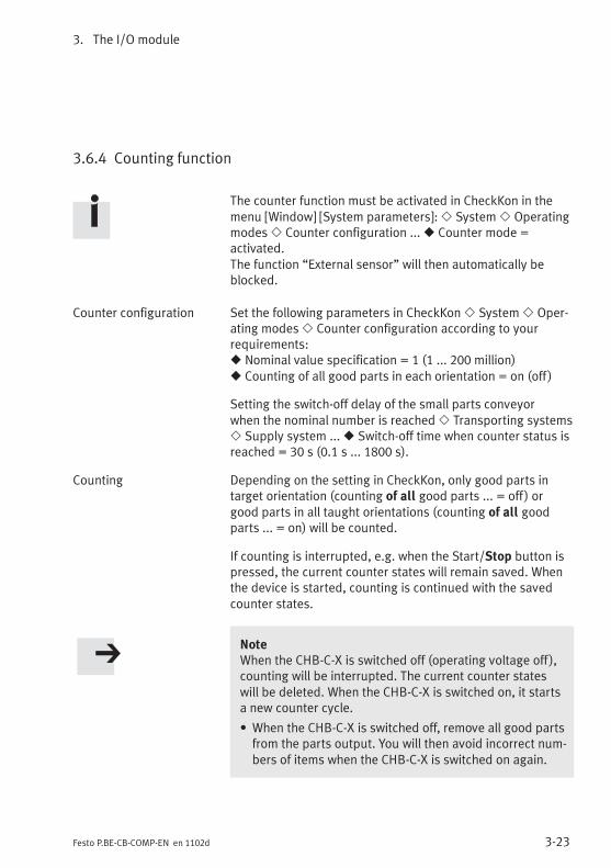
3.6.4 Counting function
The counter function must be activated in CheckKon in themenu [Window] [System parameters]:� System� Operatingmodes� Counter configuration ...� Counter mode =activated.The function “External sensor” will then automatically beblocked.
Counter configuration Set the following parameters in CheckKon� System� Oper-ating modes� Counter configuration according to yourrequirements:� Nominal value specification = 1 (1 ... 200 million)� Counting of all good parts in each orientation = on (off )
Setting the switch-off delay of the small parts conveyorwhen the nominal number is reached� Transporting systems� Supply system ...� Switch-off time when counter status isreached = 30 s (0.1 s ... 1800 s).
Counting Depending on the setting in CheckKon, only good parts intarget orientation (counting of all good parts ... = off ) orgood parts in all taught orientations (counting of all goodparts ... = on) will be counted.
If counting is interrupted, e.g. when the Start/Stop button ispressed, the current counter states will remain saved. Whenthe device is started, counting is continued with the savedcounter states.
NoteWhen the CHB-C-X is switched off (operating voltage off ),counting will be interrupted. The current counter stateswill be deleted. When the CHB-C-X is switched on, it startsa new counter cycle.
• When the CHB-C-X is switched off, remove all good partsfrom the parts output. You will then avoid incorrect num-bers of items when the CHB-C-X is switched on again.
3. The I/O module
3-24 Festo P.BE-CB-COMP-EN en 1102d
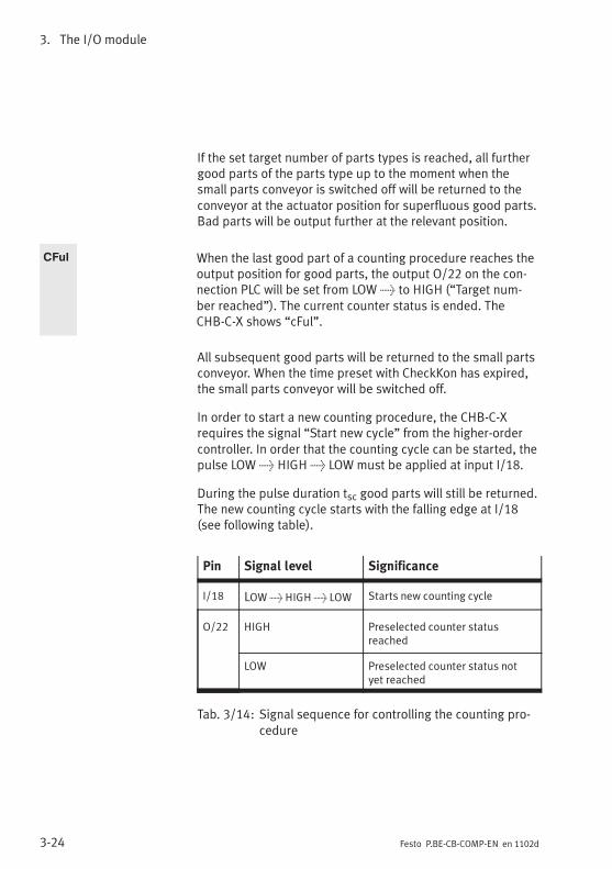
If the set target number of parts types is reached, all furthergood parts of the parts type up to the moment when thesmall parts conveyor is switched off will be returned to theconveyor at the actuator position for superfluous good parts.Bad parts will be output further at the relevant position.
CFul When the last good part of a counting procedure reaches theoutput position for good parts, the output O/22 on the con-nection PLC will be set from LOW> to HIGH (“Target num-ber reached”). The current counter status is ended. TheCHB-C-X shows “cFul”.
All subsequent good parts will be returned to the small partsconveyor. When the time preset with CheckKon has expired,the small parts conveyor will be switched off.
In order to start a new counting procedure, the CHB-C-Xrequires the signal “Start new cycle” from the higher-ordercontroller. In order that the counting cycle can be started, thepulse LOW> HIGH> LOW must be applied at input I/18.
During the pulse duration tsc good parts will still be returned.The new counting cycle starts with the falling edge at I/18(see following table).
Pin Signal level Significance
I/18 LOW> HIGH> LOW Starts new counting cycle
O/22 HIGH Preselected counter statusreached
LOW Preselected counter status notyet reached
Tab. 3/14: Signal sequence for controlling the counting pro-cedure

3. The I/O module
3-25Festo P.BE-CB-COMP-EN en 1102d
Pulse-time diagramControl of counting
Pin I/18Start new counting cycletsc , 15 ms
Pin O/22Preselected counter statusreached
0
1
0
1t sc
t r
Start
10 ms
sc = start counting cycler = reset
Tab. 3/15: Pulse-time diagram: Controlling the countingprocedure

3. The I/O module
3-26 Festo P.BE-CB-COMP-EN en 1102d
3.6.5 Actuators
NoteThis chapter contains supplementary information on con-trolling the actuators via the PLC interface. Note also theinstructions and information in Chapter 3.2.
Internal circuitry The inputs actuators 1 ... 3 at the PLC connection areconnected internally with the ACTUATORS connection.
Actuators PLC Function
3 4 GND
O/4 O/1 Actuator 1
O/2 O/2 Actuator 2
O/1 O/3 Actuator 3
Tab. 3/16: Internal circuitry ACTUATORS-PLC
Monitoring Input I/19 on the PLC plug is intended for monitoring thepneumatic supply to the actuators. In the event of a fault thisinput will switch the CHB-C-X to fault status E 01 by means ofa pressure switch.
Runtime performance Observe the following when evaluating the output signals“Actuator...” through a higher-order controller:With a high pulse rate of the test parts, parts can be returnedalthough other parts which have already been tested are notyet delivered. This delay arises due to the (long) distancebetween the actuator positions.

3. The I/O module
3-27Festo P.BE-CB-COMP-EN en 1102d
3.6.6 Buffer zone sensors/small parts conveyor
NoteThis chapter contains supplementary information on con-trolling the small parts conveyor and the buffer zonesensors via the PLC interface. Note also the instructionsand information in Chapter 3.3.
Internal circuitry The I/O signals for buffer zone sensors and the small partsconveyor at the PLC connection are connected internally withthe BUFFER/FEEDER connection.
BUFFERFEEDER
PLCFunction
O/1 O/21
– 24 V reference voltage for buf-fer zone sensors
– Ready status– Controlling the conveyor device
O/2 O/8 24 V power output for controllinga small parts conveyor (feeder)
O/3 O/40 V reference voltagebuffer zone sensors
I/4 I/12 Buffer zone sensor 1
Tab. 3/17: Internal circuitry BUFFER/FEEDER-PLC
Switch-on delay of the small parts conveyor
After starting, the Checkbox triggers the actuator for sortingout the bad parts. This is to ensure that no (unchecked) partsare left on the conveyor device. This results in a delay of afew seconds between the external Start command (I/6) andthe switch-on signal for the small parts conveyor (O/8). Theduration of this delay depends on ambient parameters,e.g. transporting speed and geometrical variables.

3. The I/O module
3-28 Festo P.BE-CB-COMP-EN en 1102d
Pulse-time diagramControlling the small parts conveyor
Pin I/6Ext_Start
Pin O/8Feeder
Pin O/21BoxReady
t d
Start Stop
0
1
0
1
0
1
t d = duration of the switch-on delay d = delay
Tab. 3/18: Pulse-time diagram: Controlling the small partsconveyor
Buffer zone sensors
With CheckKon, the CHB-C-X can be configured for operationeither with one buffer zone sensor or for switching delay ofthe small parts conveyor with two buffer zone sensors (Fig. 3/2):Menu [Window] [System parameters]� Transporting systems� Continuing systems� Number of buffer zone sensors = 1 (2).
The maximum number of parts types is reduced to 4 withthe setting “Number of buffer zone sensors = 2”(See Chapter 3.6.3).

3. The I/O module
3-29Festo P.BE-CB-COMP-EN en 1102d
1 Buffer zone
2 Conveyor device
3 Sensor 2
4 Sensor 11
2
3
4
Fig. 3/2: Buffer zone check with switching delay
Sensor type FunctionBuffer zone with one or twosensors
Normallyopencontact 1)
Normallyclosedcontact 2)
Sensor 1LOW
Sensor 1HIGH
The sensor does not register aconveyed part. The small partsconveyor is/remains switched on.
Sensor ... 3)
HIGHSensor ...3)
LOWThe buffer zone is full. The displayswitches to “Full”. Good parts arereturned. When the preset timehas expired, the small parts con-veyor will be switched off; theconveyor device still runs.
1) Factory presetting; negative switching (NPN),24 V DC active high
2) To be set with CheckKon (recommendation); positive switching(PNP), 24 V DC active low
3) with buffer zone monitoring– with one sensor: Sensor 1– with two sensors: Sensor 2
Tab. 3/19: Sensor function for type NPN or PNP
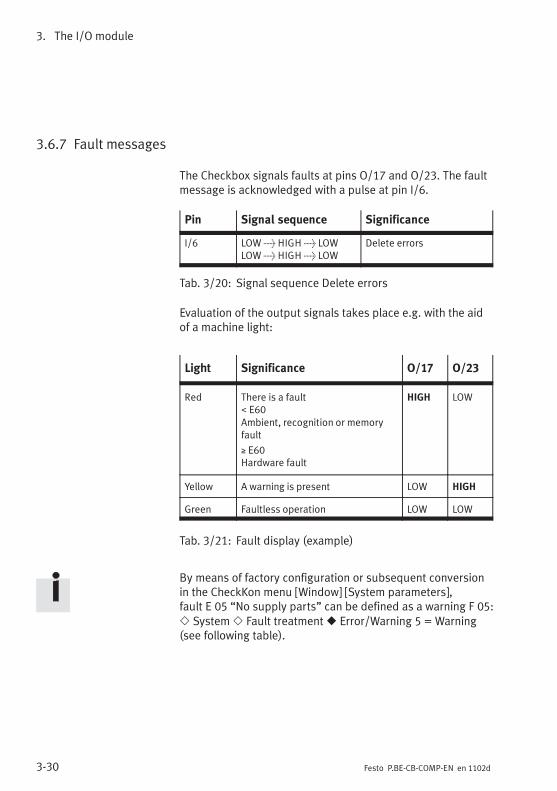
3. The I/O module
3-30 Festo P.BE-CB-COMP-EN en 1102d
3.6.7 Fault messages
The Checkbox signals faults at pins O/17 and O/23. The faultmessage is acknowledged with a pulse at pin I/6.
Pin Signal sequence Significance
I/6 LOW> HIGH> LOWLOW> HIGH> LOW
Delete errors
Tab. 3/20: Signal sequence Delete errors
Evaluation of the output signals takes place e.g. with the aidof a machine light:
Light Significance O/17 O/23
Red There is a fault. E60Ambient, recognition or memoryfault
≥ E60Hardware fault
HIGH LOW
Yellow A warning is present LOW HIGH
Green Faultless operation LOW LOW
Tab. 3/21: Fault display (example)
By means of factory configuration or subsequent conversionin the CheckKon menu [Window] [System parameters],fault E 05 “No supply parts” can be defined as a warning F 05:� System� Fault treatment� Error/Warning 5 = Warning(see following table).

3. The I/O module
3-31Festo P.BE-CB-COMP-EN en 1102d
Malfunction Code O/17 O/23
Material blockage or smallparts conveyor is empty.
E 05 (fault) HIGH LOW
F 05 (warning) LOW HIGH
Tab. 3/22: Fault/warning “No supply parts”
3.6.8 Locking the control panel
Via pin I/11, the buttons START/STOP and STATUS/TEACH onthe CHB-C-X can be locked against unauthorized actuation.The Checkbox can then be started or stopped only via pin I/6.A change to the TEACH mode is not possible.
Pin Signal level Significance
I/11 HIGH Button lock
LOW Button release
Tab. 3/23: Signal level: Locking the control panel
Display Significance
Lock Locking the control panel– Continuous display in Stop status– Display (duration 1.5 s) when the START/STOP
button is pressed.
Tab. 3/24: Display: Locking the control panel

3. The I/O module
3-32 Festo P.BE-CB-COMP-EN en 1102d
Setting the control panel lock with CheckKon
The STATUS/TEACH button can also be locked via CheckKon.At I/11 only the START/STOP button can then be released.
Fix If “Fix” is in the display, the STATUS/TEACH button is lockedwith CheckKon (blocking the Teach button = on).Acknowledge the message with the START/STOP button.
The STATUS/TEACH button remains blocked until the functionis switched off again in the menu [Window] [Systemparameters]:� System� Operating modes� Blocking theTeach button = off.

Teaching parts
4-1Festo P.BE-CB-COMP-EN en 1102d
Teaching parts
Chapter 4

4. Teaching parts
4-2 Festo P.BE-CB-COMP-EN en 1102d
Contents
4. Teaching parts 4-1. . . . . . . . . . . . . . . . . . . . . . . . . . . . . . . . . . . . . . . . . . . . . . . . .
4.1 Preparing the Teach procedure 4-3. . . . . . . . . . . . . . . . . . . . . . . . . . . . . . . . . . . .
4.2 The Teach procedure 4-5. . . . . . . . . . . . . . . . . . . . . . . . . . . . . . . . . . . . . . . . . . . .
4.2.1 Positioning the sample parts 4-9. . . . . . . . . . . . . . . . . . . . . . . . . . . . . .
4.2.2 Observing the scatter of characteristics 4-10. . . . . . . . . . . . . . . . . . . . .
4. Teaching parts
4-3Festo P.BE-CB-COMP-EN en 1102d
4.1 Preparing the Teach procedure
If you are using the CheckKon/CheckOpti software package:note also the instructions on preparing the Teach procedurein the software manuals.
Features and properties of the conveyed parts
The Checkbox registers conveyed parts as 2-dimensional,black and white profile pictures (parts contour). Features fordistinguishing various good parts are derived from the partscontour. Discolouring or surface faults do not influence thetest result in this recognition procedure.
The features of the conveyed part relevant for distinguishing,as well as for determining the orientation and quality, mustbe recognizable for the Checkbox:
� Use the Checkbox preferably for testing rotation-symmet-rical small parts.The testing of non-rotation-symmetrical parts is only pos-sible if a pre-orientation of the conveyed parts is carriedout with the small parts conveyor.
The conveyed part must be fed through in a safe manner onthe conveyor device:
– The length, diameter and height of a conveyed part mustbe suitable for the CHB-C-X.
– The conveyed part must be supplied in a stable orienta-tion (it must not roll away or vibrate).
The conveyed part must be sorted out reliably by theactuators.
As standard during the Teach procedure, the parts are sortedout at the first actuator position. This is to ensure that nosample parts are transported by mistake to the next machinein the process.

4. Teaching parts
4-4 Festo P.BE-CB-COMP-EN en 1102d
NoteCheck in the test mode whether the actuators used (e.g. airnozzles) can reliably sort out especially large conveyedparts made of heavy materials with streamlined form.This is to ensure that no sample parts are transported bymistake to the next machine in the process.
Selecting the sample parts
� Provide sample parts for each parts type as follows:
– The sample parts show all the characteristics which apart classified as “Good” should possess.
– If possible, use various sample parts with theusual scatter of characteristics (recommendation:min. 6 sample parts). With the scatter of characterist-ics, you determine the extent to which the test partsclassified as “Good” may differ from each other.
Diagnostics mode
� Start CheckKon in order to display and set the systemparameters during the TEACH and test modes.
When Checkkon is started, it carries out a system test andswitches the Checkbox automatically to the diagnostic mode.
NoteIn the diagnostic mode the Checkbox transmits additionalinformation via the diagnostic interface. During the trans-mission time no parts are checked.
• Do not operate the Checkbox in diagnostic mode withthe full parts rate.
In this way you can prevent parts from passing the actu-ator positions unchecked.

4. Teaching parts
4-5Festo P.BE-CB-COMP-EN en 1102d
4.2 The Teach procedure
In the TEACH mode the Checkbox learns all the features forthe parts test (Teach data) when scanning sample parts.
� Carry out the Teach procedure as realistically as possible.Use, for example, the conveyor device and feed intendedfor the later AUTO mode (if necessary activate withCheckKon: [Window] [System parameters]� Transportingsystems� Supply system ...� Activate supply system inTeach mode ...).
� Start the conveyor device.
The following functions of the Teach procedure can be carriedout via the PLC interface:
– START/STOP mode
– selection of the parts type
– starting of the Teach mode
– selection of the (next) orientation
– saving of the Teach data
� Set the desired parts type via the PLC interface.
Further information can be found in Chapter 3.6
Stop• Press the button START/STOP, in order to switch the
Checkbox into the Stop status.
� Scan sample parts of the parts type one after the other inall intended orientations (max. 8), as described below.

4. Teaching parts
4-6 Festo P.BE-CB-COMP-EN en 1102d
Scan sample parts in orientation 1
1. Press the button STATUS/TEACH, in order to switch theCheckbox to the Teach mode.
Fix If “Fix” is shown in the display and if the CHB-C-X switchesto the AUTO mode again, the STATUS/TEACH button isblocked by CheckKon. Acknowledge the message with theSTART/STOP button.
• Switch off the TEACH button blocking with CheckKon:[Window] [System parameters]� System� Operatingmodes = ...� Teach button lock = Off.
1 o1 2. Scan different sample parts of parts type 1 in orienta-tion 1 (o1 = nominal orientation). The STATUS/TEACHbutton lights up briefly when the sample part isregistered.
• Pay attention to the positioning of the sample parts(see Chapter 4.2.1).
C ... • While scanning, observe the displayed C-value of thescatter of characteristics (see Chapter 4.2.2).
• Repeat the procedure until the C-value remainsalmost constant.
If a part has been incorrectly positioned (C-value changeserratically):
� Press the button START/STOP, in order to conclude theTeach procedure.
� Repeat the complete Teach procedure of the parts type.

4. Teaching parts
4-7Festo P.BE-CB-COMP-EN en 1102d
Scan the sample parts in further orientations
3. Check whether there is at least one feature in which thevarious orientations differ.
4. Press the STATUS/TEACH button in order to scan the nextorientation
E 20If fault E20 is shown, the nominal orientation cannot be dis-tinguished from other orientations.
Possible causes of the fault:
– The nominal orientation has been taught several times bymistake.
� Repeat the complete teach procedure. Pay attentionto the positioning of the sample parts in accordancewith the orientation shown.
– The nominal orientation is too similar to other orienta-tions.
� Optimize the Teach data with CheckOpti.
With the CheckOpti software even minimum differences in thefeatures can be recognized. Further information can be ob-tained from your technical advisor.
1 o25. Scan the sample parts of parts type 1 in orientation 2
(o2) as described in point 2.
4. Teaching parts
4-8 Festo P.BE-CB-COMP-EN en 1102d
Save the Teach data and conclude the Teach procedure
Do not save the Teach data until the sample parts of a partstype have been taught in all orientations.
Stop 6. Press the START/STOP button.The Teach data will be saved and the TEACH mode will beconcluded.
After saving, carry out the following steps:
� Check the Teach procedure in the test mode with regardto orientation and quality as described in Chapter 5.
� Keep a record of your work.
Register the next parts type in a further Teach procedure:
� Address the next parts type via the PLC inputs(Chapter 3.6.3).
� Repeat all steps as from point 1.

4. Teaching parts
4-9Festo P.BE-CB-COMP-EN en 1102d
4.2.1 Positioning the sample parts
The sample parts should be positioned exactly like the partsto be tested later.
– Place the sample parts on the conveyor band one afterthe other.
– You do not need to be very careful when placing the partson the conveyor belt.
In cases where particularly different variations of theascertained parts contour (view) are permitted or possible inan orientation, you should show the “extreme” variations oras many different variations as possible during the teachprocedure.
� Show at least 6 parts of the current parts type perorientation.
� Use different parts if possible, although if necessary thesame part can be shown several times.
The parts type is not registered completely until theCheckbox has recorded all intended orientations. For reliabletesting, the ascertained features of the individual orientationsmust be clearly distinguished.
� Make sure in particular that orientation 1 (target orienta-tion) differs clearly in at least one feature from all theother orientations.

4. Teaching parts
4-10 Festo P.BE-CB-COMP-EN en 1102d
4.2.2 Observing the scatter of characteristics
C... Observe the display when scanning the sample parts. Itshows briefly for each part the maximum value of the scatterof characteristics for the current feature which differs to thegreatest extent (C-value).
The following factors influence the scatter of characteristics:
– parts geometry
– different contours of the part, depending on the swivelangle around the longitudinal axis (e.g. with springs,screws)
– different positioning on the conveyor device.
If the displayed C-value changes erratically, you have prob-ably placed the conveyed part incorrectly on the conveyordevice. If the C-value changes only minimally, a sufficientscatter of characteristics in the current orientation has prob-ably been achieved. The optimum situation is when the curveof the values changes at first considerably and then becomesincreasingly more constant.
Small values indicate narrow manufacturing tolerances and asteady supply of parts. Very large values indicate that thetaught sample parts differ greatly from each other withregard to their properties. If the (good) parts are allowed todiffer greatly from each other, the Teach procedure cannevertheless still be continued.
C-value Significance
. 10 Sample parts are very similar in all features
, 30 Large scatter of at least one feature
An exact description of the calculation algorithm for the scatter ofcharacteristics can be found in Appendix A.3.2.
Tab. 4/1: C-value (scatter of characteristics)

Testing parts
5-1Festo P.BE-CB-COMP-EN en 1102d
Testing parts
Chapter 5

5. Testing parts
5-2 Festo P.BE-CB-COMP-EN en 1102d
Contents
5. Testing parts 5-1. . . . . . . . . . . . . . . . . . . . . . . . . . . . . . . . . . . . . . . . . . . . . . . . . .
5.1 The test procedure 5-3. . . . . . . . . . . . . . . . . . . . . . . . . . . . . . . . . . . . . . . . . . . . . .
5.2 Test mode 5-4. . . . . . . . . . . . . . . . . . . . . . . . . . . . . . . . . . . . . . . . . . . . . . . . . . . . .
5.3 Influence of tolerance 5-7. . . . . . . . . . . . . . . . . . . . . . . . . . . . . . . . . . . . . . . . . . .
5.4 Evaluation of the test results 5-9. . . . . . . . . . . . . . . . . . . . . . . . . . . . . . . . . . . . . .
5.4.1 Checking the features 5-9. . . . . . . . . . . . . . . . . . . . . . . . . . . . . . . . . . . .
5.4.2 Checking the orientation 5-10. . . . . . . . . . . . . . . . . . . . . . . . . . . . . . . . . .

5. Testing parts
5-3Festo P.BE-CB-COMP-EN en 1102d
5.1 The test procedure
During the automatic inspection of workpieces, a reliablegrading of the parts to be tested must be achieved withrespect to orientation and quality (e.g. dimensions specifiedhave been observed).
The following functions can only be carried out via the PLCinterface:
– Selection of the parts type
– Counter function or test with external sensor
– Monitoring of the buffer zone with switch delay.
Further information can be found in Chapter 3.6.
� Evaluate the reliability of the Teach data in the test mode(Chapter 5.2), before you begin with the automaticinspection of workpieces.
� Protect the Teach data against undesired modification:
– through control panel protection (see Chapter 3.6.8)
– with the CheckKon software:[Window] [System parameters]� System� Operatingmodes ...� Teach button lock = On.
5. Testing parts
5-4 Festo P.BE-CB-COMP-EN en 1102d
5.2 Test mode
Stop The Teach procedure is concluded and the Checkbox isready to operate (Stop status)
Set the desired parts type via the PLC interface (Chapter 3.6.3)
1. Provide inspection parts for each parts type
� Use good, bad and incorrectly oriented parts from theparts assortment.
� Test a sufficient number of parts in order to obtain areproducible result.Show, for example, 6 good parts per orientation aswell as 6 bad parts.
1 5 2. Press the button START/STOP (AUTO mode). Test partsfrom the displayed parts type (e.g. 1) with the factory-settolerance of 5 %.
3. You do not need to be very careful when placing the partson the conveyor belt.If possible, use the conveyor device intended for theinspection of workpieces. The inspection parts should bepositioned (at random), as in normal operation.
E 05 If the supply of parts is interrupted for a long period, theCheckbox will show fault message E 05 or warning F 05 andwill stop automatically (see Chapter 2.6 and Appendix A.1.2).
4. Check the test results e.g. with regard to the followingaspects: Have the orientations been recognized correctly?Is the grading of the parts recognized as good/badcorrect?

5. Testing parts
5-5Festo P.BE-CB-COMP-EN en 1102d
5. Check the correct output at the output positions for good,bad or incorrectly oriented parts with as many inspectionparts as possible.
6. On the basis of the sample parts, check the inspectionparts with regard to their grading. If you have also testedfaulty parts, check whether these have actually beenrecognized as bad.
If too many good parts have been graded and sorted outas “Bad”:
� Increase the tolerance (see Chapter 5.3)
� Repeat the Teach procedure with more sample parts,using the conveyor device intended for automaticmode (see Chapter 4).
7. Note the displays on the Checkbox.When a conveyed part is registered, the status displaylights up briefly.
The display shows for 1.5 seconds:
A...
#...
• The evaluation of the inspection part deviation A(Chapter 6.4.2)
• The evaluation of the inspection part orientation #if more than one orientation has been learnt(Chapter 6.4.3).
If the quality check and position recognition for the partsassortment are not satisfactory, you can use additionaloperating parameters and tools with CheckOpti in order tooptimize the test results. Please consult your technicaladvisor.

5. Testing parts
5-6 Festo P.BE-CB-COMP-EN en 1102d
Terminate the test mode when all settings have been com-pleted and the checked parts have been graded reliably withregard to orientation and quality.
Stop 8. Press the button START/STOP, in order to switch theCheckbox into the Stop status.
9. Conclude the diagnostic mode. Close CheckKon (andCheckOpti).
10. Remove the diagnostic cable from the DIAG connectionand seal the connection with the protective cap supplied.

5. Testing parts
5-7Festo P.BE-CB-COMP-EN en 1102d
5.3 Influence of tolerance
Band width When a new parts type is taught, the features of all scannedparts are recorded. The values of the registered features dif-fer individually from each other. For each feature, there is avalue range (band width) in which test parts are graded as“Good”. You can influence this band width by means of thetolerance setting. Test parts, the features of which lie withinthe band width or in the subsequent tolerance range, are stillaccepted as good parts.
With 0 % tolerance, only those parts with features which lieexactly within the band width of the scanned sample partswill be accepted as good parts. Set therefore at least 1 %tolerance. This will ensure that good parts will be classifiedcorrectly even if their positions deviate minimally.
Set tolerance The setting is made in the Stop status.
Stop 1. Press the button START/STOP, in order to switch theCheckbox into the Stop status.
1 5
1 10
2. Press and hold down the START/STOP button whileyou increase the tolerance value by pressing theTEACH/STATUS button, e.g. from 5 to 10%:
Setting range 0 ... 20 %Standard setting 5 %Recommendation at least 1 %
Stop 3. Release the START/STOP button when the desired valuehas been set.
The value selected will be added automatically to the data ofthe parts type and saved.

5. Testing parts
5-8 Festo P.BE-CB-COMP-EN en 1102d
Optimizing Ascertain the optimum setting of the tolerance especially withcritical conveyed parts in the test mode. Use one of thefollowing methods:
� Empirical settingVary the tolerance so that the test of a large number ofparts produces correctly recognized good and bad parts.
� Setting corresponding to inspection part deviation:
� Select sample parts which are suitable as referencefor good or bad parts. The recognition-specificfeatures should lie if possible in the limit rangegood/bad.
� Vary the tolerance so that the following test part devi-ation is shown when the limit sample part is scanned:‹ 100 limit sample part “Good”› 100 limit sample part “Bad”

5. Testing parts
5-9Festo P.BE-CB-COMP-EN en 1102d
5.4 Evaluation of the test results
5.4.1 Checking the features
The individual features of the inspection parts differ from theaverage values of the sample part features. The Checkboxascertains the feature which differs most (maximum deviation)for each test part.
A... During the test procedure the inspection part deviationwill be shown for 1.5 seconds. Detailed instructions on testpart deviation (arithmetical algorithm) can be found inAppendix A.3.3.
Value Evaluation Note
≤100 Good part The smaller the value,the more accurately theinspection part corres-ponds to the sampleparts.
>100 Reject part The larger the value,the less the inspectionpart corresponds to thesample parts.
Indicating range: 0 to 999
Tab. 5/1: Inspection part deviation

5. Testing parts
5-10 Festo P.BE-CB-COMP-EN en 1102d
5.4.2 Checking the orientation
The Checkbox ascertains during the test procedure whetherthe orientation of the last scanned test part can be assignedto the orientations of the sample part.
#... The uncertainty in orientation recognition will be shownfor 1.5 seconds after the display of the inspection partdeviation.
Value Evaluation Significance
<100 Inspection partorientation can beassigned
The smaller the value,the more reliably theinspection partorientation will berecognized.
>100 Inspection partorientation cannot beassigned clearly
The larger the value,the less reliably theinspection partorientation will berecognized.
Indicating range: 0 to 999
Tab. 5/2: Uncertainty of orientation recognition

Maintenance
6-1Festo P.BE-CB-COMP-EN en 1102d
Maintenance
Chapter 6

6. Maintenance
6-2 Festo P.BE-CB-COMP-EN en 1102d
6. Maintenance 6-1. . . . . . . . . . . . . . . . . . . . . . . . . . . . . . . . . . . . . . . . . . . . . . . . . .

6. Maintenance
6-3Festo P.BE-CB-COMP-EN en 1102d
CautionDamage to components
• Before carrying out mounting, installation and/or main-tenance work, always switch off the power supply.
NoteDamage to the glass surfaces can result in operative mal-functions of the Checkbox.
• Consult your Festo Service in case of damage.
The Checkbox has been designed for rough industrialenvironments and is distinguished by its high reliability,robust structure and long service life. Special maintenancework is not necessary.
Cleaning Fixed cleaning intervals are not specified. The frequency ofcleaning depends on the conditions of use at your location.
Laser irradiationEye and skin injury
• Clean the Checkbox only in the switched-off state.
• Observe the warnings on the Checkbox.
With plastic parts, do not use solvent-containing or abrasivecleaning agents, which can damage the surfaces. Use onlymild cleaning agents free of solvents.
� Remove dirt from the housing, operating elements andconveyor belt with a soft moist cloth.

6. Maintenance
6-4 Festo P.BE-CB-COMP-EN en 1102d
NoteFaultless functioning of the Checkbox optics can only beguaranteed if the glass surfaces are clean and notscratched. Make sure that the glass surfaces are notscratched; do not use any abrasive cleaning agents.
Clean the glass surfaces on the prism supports if they aredirty or if there are dirt deposits on them:
• with clean non-lubricated compressed air
• with a soft moist cloth and non-abrasive cleaning agents.
You will then avoid damage which could lead to malfunc-tioning of the Checkbox.

Technical appendix
A-1Festo P.BE-CB-COMP-EN en 1102d
Technical appendix
Appendix A
A. Technical appendix
A-2 Festo P.BE-CB-COMP-EN en 1102d
Contents
A. Technical appendix A-1. . . . . . . . . . . . . . . . . . . . . . . . . . . . . . . . . . . . . . . . . . . . .
A.1 Operating malfunctions A-3. . . . . . . . . . . . . . . . . . . . . . . . . . . . . . . . . . . . . . . . . .
A.1.1 General fault finding A-3. . . . . . . . . . . . . . . . . . . . . . . . . . . . . . . . . . . . .
A.1.2 Fault messages and warnings A-4. . . . . . . . . . . . . . . . . . . . . . . . . . . . . .
A.2 Status displays on the control panel A-9. . . . . . . . . . . . . . . . . . . . . . . . . . . . . . . .
A.3 Examples for calculation of the features A-12. . . . . . . . . . . . . . . . . . . . . . . . . . . . .
A.3.1 Band width and tolerance A-12. . . . . . . . . . . . . . . . . . . . . . . . . . . . . . . . .
A.3.2 Scatter of characteristics A-14. . . . . . . . . . . . . . . . . . . . . . . . . . . . . . . . .
A.3.3 Inspection part deviation A-15. . . . . . . . . . . . . . . . . . . . . . . . . . . . . . . . .
A.4 Connections A-17. . . . . . . . . . . . . . . . . . . . . . . . . . . . . . . . . . . . . . . . . . . . . . . . . . .
A.5 Technical data A-22. . . . . . . . . . . . . . . . . . . . . . . . . . . . . . . . . . . . . . . . . . . . . . . . . .
A.6 Accessories A-25. . . . . . . . . . . . . . . . . . . . . . . . . . . . . . . . . . . . . . . . . . . . . . . . . . . .
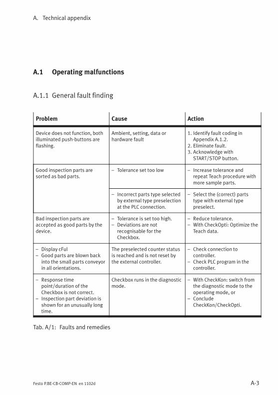
A. Technical appendix
A-3Festo P.BE-CB-COMP-EN en 1102d
A.1 Operating malfunctions
A.1.1 General fault finding
Problem Cause Action
Device does not function, bothilluminated push-buttons areflashing.
Ambient, setting, data orhardware fault
1. Identify fault coding inAppendix A.1.2.
2. Eliminate fault.3. Acknowledge with
START/STOP button.
Good inspection parts aresorted as bad parts.
– Tolerance set too low – Increase tolerance andrepeat Teach procedure withmore sample parts.
– Incorrect parts type selectedby external type preselectionat the PLC connection.
– Select the (correct) partstype with external typepreselect.
Bad inspection parts areaccepted as good parts by thedevice.
– Tolerance is set too high.– Deviations are not
recognisable for theCheckbox.
– Reduce tolerance.– With CheckOpti: Optimize the
Teach data.
– Display cFul– Good parts are blown back
into the small parts conveyorin all orientations.
The preselected counter statusis reached and is not reset bythe external controller.
– Check connection tocontroller.
– Check PLC program in thecontroller.
– Response timepoint/duration of theCheckbox is not correct.
– Inspection part deviation isshown for an unusually longtime.
Checkbox runs in the diagnosticmode.
– With CheckKon: switch fromthe diagnostic mode to theoperating mode, or
– ConcludeCheckKon/CheckOpti.
Tab. A/1: Faults and remedies
A. Technical appendix
A-4 Festo P.BE-CB-COMP-EN en 1102d
A.1.2 Fault messages and warnings
The Checkbox stops automatically if there is a malfunction.When the cause of the malfunction has been eliminated, errormessages/warnings must be acknowledged before theCheckbox can start again.
1. Eliminate cause of malfunction
2. Acknowledge the fault signals: Press the START/STOPbutton
3. Start the Checkbox: Press the START/STOP button
Depending on the customer-specific design of the Checkboxor configuration with CheckKon, the following faults will notbe shown:
– The error messages E 01, E 02, E 04, E 06, E 08, E 12,E 14 can be deactivated.
– Fault E 05 is redefined as warning F 05 or deactivated.
– Faults E 08 and E 14 are only shown with encoder mode.
– Fault E 06 is shown only if the CheckKon function “Forcedabort of analysis” is activated.
NoteIf fault messages and warnings are deactivated, undefinedoperating states and malfunctioning can occur in the eventof a fault. Before deactivating, check whether additionalmeasures are necessary for avoiding faults.
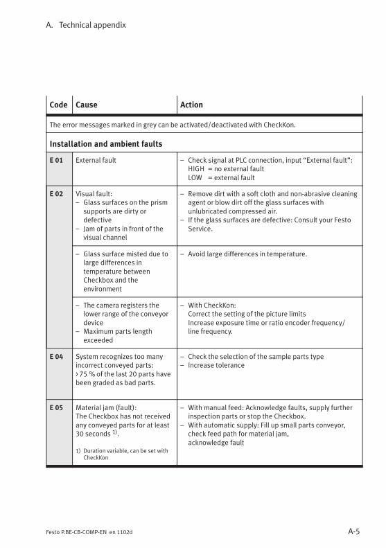
A. Technical appendix
A-5Festo P.BE-CB-COMP-EN en 1102d
Code Cause Action
The error messages marked in grey can be activated/deactivated with CheckKon.
Installation and ambient faults
E 01 External fault – Check signal at PLC connection, input “External fault”:HIGH = no external faultLOW = external fault
E 02 Visual fault:– Glass surfaces on the prism
supports are dirty ordefective
– Jam of parts in front of thevisual channel
– Remove dirt with a soft cloth and non-abrasive cleaningagent or blow dirt off the glass surfaces withunlubricated compressed air.
– If the glass surfaces are defective: Consult your FestoService.
– Glass surface misted due tolarge differences intemperature betweenCheckbox and theenvironment
– Avoid large differences in temperature.
– The camera registers thelower range of the conveyordevice
– Maximum parts lengthexceeded
– With CheckKon:Correct the setting of the picture limitsIncrease exposure time or ratio encoder frequency/line frequency.
E 04 System recognizes too manyincorrect conveyed parts:> 75 % of the last 20 parts havebeen graded as bad parts.
– Check the selection of the sample parts type– Increase tolerance
E 05 Material jam (fault):The Checkbox has not receivedany conveyed parts for at least30 seconds 1).
1) Duration variable, can be set withCheckKon
– With manual feed: Acknowledge faults, supply furtherinspection parts or stop the Checkbox.
– With automatic supply: Fill up small parts conveyor,check feed path for material jam,acknowledge fault

A. Technical appendix
A-6 Festo P.BE-CB-COMP-EN en 1102d
Code ActionCause
F 05 Material jam (warning)Signal on plug PLC O/23 = HIGHThe Checkbox has not receivedany conveyed parts for at least30 seconds 1).1) Duration variable, can be set with
CheckKon
– With manual feed: Acknowledge faults, supply furtherinspection parts or stop the Checkbox.
– With automatic supply: Fill up small parts conveyor,check feed path for material jam,acknowledge warning.
E 06 Maximum permitted partslength exceededFault E 06 is shown only if theCheckKon function “Forcedabort of analysis” is switchedon.
– With CheckKon: Set the parameter “Max. parts length”correctly
– Set the conveyor device so that the partsfollow each other at a recognizable distance.
E 07 Visual fault:Reduced brightness
Clean the glass surfaces on the prism.
E 08 Only for operation withencoder:Conveyor device blocked orencoder does not turn.
Checkbox has no control over the conveyor device.– Check the fitting and installation of the encoder.
E 09E 10
Overload of internalI/O module
1. Stop the Checkbox2. Check whether external outputs are loaded with an
excessive current3. Start the Checkboxor contact the Festo after-sales service.
E 12 Overtemperature – Check ambient temperature– Prevent warmth from outside e.g. by sun shine.
E 14 Only for operation withencoder:Conveyor speed for the setratio encoder frequency/line frequency of the camera(FEZ value) too high.
– Reduce conveyor speed– With CheckKon: Adapt FEZ value.
E 19 Incorrect operating system The operating system must be appropriate for theCHB-C-X.– Install correct operating system variant.

A. Technical appendix
A-7Festo P.BE-CB-COMP-EN en 1102d
Code ActionCause
Recognition fault
E 20 The nominal orientation cannotbe distinguished from other ori-entations, because e.g.:– the parts orientations were
swapped by mistake duringthe teach procedure, or
– the nominal orientation istoo similar to otherorientations.
– Repeat teach procedure. Pay attention to thepositioning of the sample parts in accordance with theorientation shown.
– Optimize teach data with the CheckOpti software.
Data fault
E 40 The teach data are not clear.When the device is switched onagain, the saved teach data areno longer OK.
– Repeat the teach procedure– Check the environment for devices which do not
conform to CE requirements– Make sure that all electrical connections are correctly
wired.
E 41 The controller has lost thesystem parameters
– With CheckKon: Load system parameters again– Contact the Festo after-sales service.
E 42 The controller has lost theconfiguration part of the teachdata.
– With CheckKon: Load Teach data again– Contact the Festo after-sales service.
E 43 The teach data are notcompatible.The teach data are notorganised compatibly for theCheckbox used.
– Use compatible teach data format– Repeat the teach procedure.
Tab. A/2: Fault codes
If the hardware fault message ≥ E 60 appears, please contactthe Festo after-sales service.
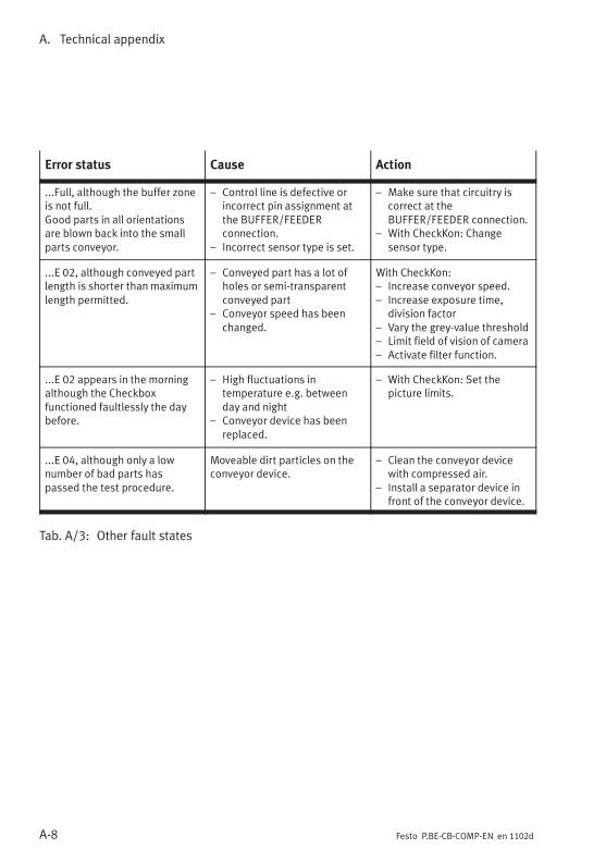
A. Technical appendix
A-8 Festo P.BE-CB-COMP-EN en 1102d
Error status Cause Action
...Full, although the buffer zoneis not full.Good parts in all orientationsare blown back into the smallparts conveyor.
– Control line is defective orincorrect pin assignment atthe BUFFER/FEEDERconnection.
– Incorrect sensor type is set.
– Make sure that circuitry iscorrect at theBUFFER/FEEDER connection.
– With CheckKon: Changesensor type.
...E 02, although conveyed partlength is shorter than maximumlength permitted.
– Conveyed part has a lot ofholes or semi-transparentconveyed part
– Conveyor speed has beenchanged.
With CheckKon:– Increase conveyor speed.– Increase exposure time,
division factor– Vary the grey-value threshold– Limit field of vision of camera– Activate filter function.
...E 02 appears in the morningalthough the Checkboxfunctioned faultlessly the daybefore.
– High fluctuations intemperature e.g. betweenday and night
– Conveyor device has beenreplaced.
– With CheckKon: Set thepicture limits.
...E 04, although only a lownumber of bad parts haspassed the test procedure.
Moveable dirt particles on theconveyor device.
– Clean the conveyor devicewith compressed air.
– Install a separator device infront of the conveyor device.
Tab. A/3: Other fault states

A. Technical appendix
A-9Festo P.BE-CB-COMP-EN en 1102d
A.2 Status displays on the control panel
Push-button Status Significance
START/STOP Continuous red light Checkbox is in the– AUTO mode
(Display e.g.: 1 5) or– TEACH mode
(Display e.g.: = 1 o1)
Continuous green light Checkbox is ready to operate (Stop status)(display: Stop)
STATUS/TEACH Flashes yellow New part passes the camera
START/STOP
STATUS/TEACH
Flashes red
Flashes yellow
MalfunctionDisplay fault code E... or warning F...,see Appendix A.1.2
Tab. A/4: Illuminated push-button
Operating status displays
Tables on a grey background indicate continuous displays; the remaining displays last only a shorttime as a result of an event or an operating status.
Display when the device is switched on
CC30 Identification code and version status of the operating system
4..E Number of memory modules for parts types and additionally the letter E with systemsetting “with encoder”. Example: 4 memory modules, encoder.
2048 System setting of the camera resolutionExample: 2048 pixels
Stop The Checkbox is in the Stop status
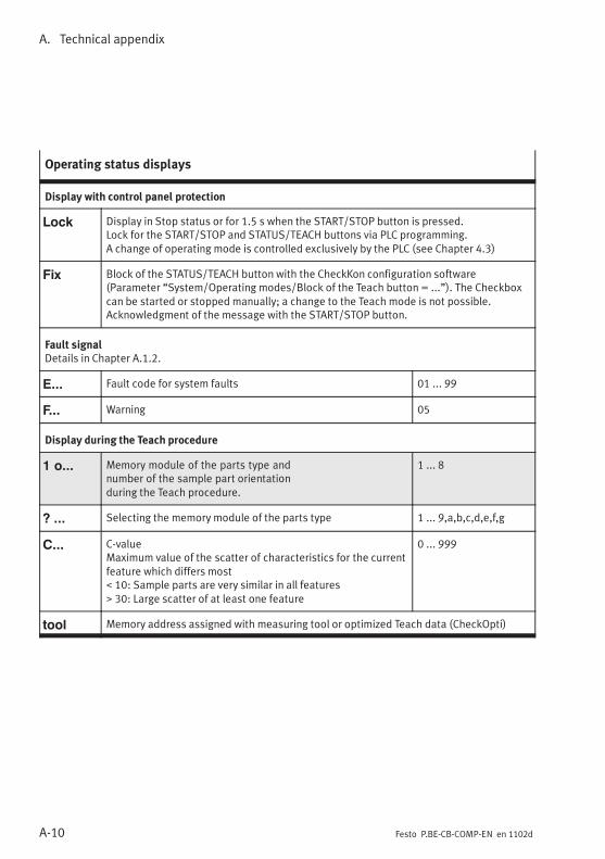
A. Technical appendix
A-10 Festo P.BE-CB-COMP-EN en 1102d
Operating status displays
Display with control panel protection
Lock Display in Stop status or for 1.5 s when the START/STOP button is pressed.Lock for the START/STOP and STATUS/TEACH buttons via PLC programming.A change of operating mode is controlled exclusively by the PLC (see Chapter 4.3)
Fix Block of the STATUS/TEACH button with the CheckKon configuration software(Parameter “System/Operating modes/Block of the Teach button = ...”). The Checkboxcan be started or stopped manually; a change to the Teach mode is not possible.Acknowledgment of the message with the START/STOP button.
Fault signalDetails in Chapter A.1.2.
E... Fault code for system faults 01 ... 99
F... Warning 05
Display during the Teach procedure
1 o... Memory module of the parts type andnumber of the sample part orientationduring the Teach procedure.
1 ... 8
? ... Selecting the memory module of the parts type 1 ... 9,a,b,c,d,e,f,g
C... C-valueMaximum value of the scatter of characteristics for the currentfeature which differs most. 10: Sample parts are very similar in all features, 30: Large scatter of at least one feature
0 ... 999
tool Memory address assigned with measuring tool or optimized Teach data (CheckOpti)
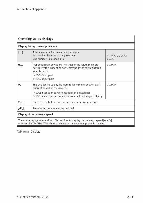
A. Technical appendix
A-11Festo P.BE-CB-COMP-EN en 1102d
Operating status displays
Display during the test procedure
1 5 Tolerance value for the current parts type1st number: Number of the parts type2nd number: Tolerance in %
1 ... 9,a,b,c,d,e,f,g0 ... 20
A... Inspection part deviation: The smaller the value, the moreaccurately the inspection part corresponds to the registeredsample parts.
≤100: Good part
>100: Reject part
0 ... 999
#... The smaller the value, the more reliably the inspection partorientation will be recognized.
<100: Inspection part orientation can be assigned
>100: Inspection part orientation cannot be assigned clearly
0 ... 999
Full Status of the buffer zone (signal from buffer zone sensor)
cFul Preselected counter setting reached
Display of the conveyor speed
The operating system version ...E is required to display the conveyor speed [mm/s].– Press the TEACH/STATUS button while the conveyor equipment is running.
Tab. A/5: Display

A. Technical appendix
A-12 Festo P.BE-CB-COMP-EN en 1102d
A.3 Examples for calculation of the features
A.3.1 Band width and tolerance
The band width B specifies how far the value of the featuremay vary upwards or downwards.The tolerance T specifies the percentage increase in the bandwidth of each feature, related to the average value of thefeature.
Cmax tol
= Cmax+A×T
100
Cmin tol
= Cmin
−A×T
100
B = Cmax tol
−Cmin tol
= Cmax− Cmin
+2× T× A
100
→ T =B−(Cmax− C
min)
2× A× 100
ABCmax
Cmax tol
Cmin
Cmin tol
T
Average value of the featureBand widthFeature maximumUpper limit of the band width incl. toleranceFeature minimumLower limit of the band width incl. ToleranceTolerance

A. Technical appendix
A-13Festo P.BE-CB-COMP-EN en 1102d
Example Ascertaining the band width for the feature “Length” of aconveyed part with a set tolerance of 5 %.
Conveyed part lengths [mm] ascertained during the Teachprocedure for 5 sample parts: 60 60 61 65 60
This means:
A = 61.2 mmCmax = 65 mmCmin = 60 mmT = 5 %
Average value of the lengthLength, maximumLength, minimumTolerance
B = Cmax − Cmin
+2× T× A
100
B = (65−60)+ 2× 5× 61.2100
B = 11, 12
1 2
68.06
65.00
61.20
60.00
56.94
Cmax tol
Cmax
A
Cmin
Cmin tol
B
1 Band width of the conveyed part length
2 Band width at 5 % tolerance
Result: All conveyed parts with a length of 57 … 68 mm areclassified as good parts. The Checkbox ascertainsappropriate value ranges for each feature.
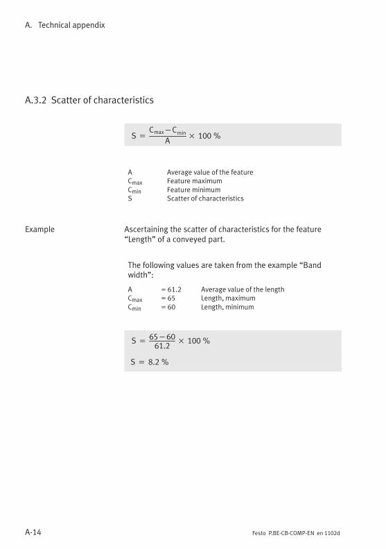
A. Technical appendix
A-14 Festo P.BE-CB-COMP-EN en 1102d
A.3.2 Scatter of characteristics
S =Cmax−C
min
A× 100 %
ACmax
Cmin
S
Average value of the featureFeature maximumFeature minimumScatter of characteristics
Example Ascertaining the scatter of characteristics for the feature“Length” of a conveyed part.
The following values are taken from the example “Bandwidth”:
A = 61.2Cmax = 65Cmin = 60
Average value of the lengthLength, maximumLength, minimum
S =65−6061.2
× 100 %
S = 8.2 %

A. Technical appendix
A-15Festo P.BE-CB-COMP-EN en 1102d
A.3.3 Inspection part deviation
Calculating the deviation D for C ‹ A
D =Cactual
−ACmin tol
−A× 100 %
ACactualCmin tol
D
Average value of the featureCurrent feature measurementLower limit of the band width incl. toleranceFeature deviation
Example Ascertaining the deviation for the current feature “Length” ofa conveyed part Cactual = 61 (C < A )
The following values are taken from the example “Bandwidth”:
A = 61.2Cmin tol = 56.94Cactual = 61
Average value of the lengthLength, lower limitLength, current value
D =61−61.2
56.94−61.2× 100 %
D = 4.7 %

A. Technical appendix
A-16 Festo P.BE-CB-COMP-EN en 1102d
Calculating the deviation D for C ‹ A
D =Cactual
−ACmax tol
−A× 100 %
ACactualCmax tol
D
Average value of the featureCurrent feature measurementUpper limit of the band width incl. ToleranceFeature deviation
Example Ascertaining the deviation for the current feature “Length” ofa conveyed part Cactual = 64 (C > A )
The following values are taken from the example “Bandwidth”:
A = 61.2Cmax tol = 68.06Cactual = 64
Average value of the lengthLength, upper limitLength, current value
D =64−61.2
68.06−61.2× 100 %
D = 40.8 %

A. Technical appendix
A-17Festo P.BE-CB-COMP-EN en 1102d
A.4 Connections
Pin 24 V DC connector plug
1 Do not connect
2 + 24 V DC, +/- 15 %; protect with5 A medium time-lag fuse
3 GND
4 Do not connect
Tab. A/6: 24 V DC connector plug
Pin BUFFER/FEEDER connector socket
O/1 24 V DC/Box ready– Reference voltage for sensors,
switched off in Stop status– Ready status– Control for transporting device
1
43
2
5
O/2 FeederControlling the supply system(small parts conveyor)
3 GNDReference voltage for sensors
I/4 Buffer zone sensor 1
5 Do not connect
Tab. A/7: BUFFER/FEEDER connector socket
Direct connection can optionally be made with a Festo Duocable (see Accessories, Appendix A.6.).

A. Technical appendix
A-18 Festo P.BE-CB-COMP-EN en 1102d
Duo cable marking
Signal x Buffer zone sensor 1
Signal x + 1 Small parts conveyor (feeder)
Tab. A/8: Duo cable marking
Pin ACTUATORS connector socket
O/1 Actuator 3
1
43
2
5
O/2 Actuator 2
3 GND
O/4 Actuator 1
5 Do not connect
Tab. A/9: ACTUATORS connector socket
Pin Connector socket DIAG 1)
I/1 Received data
1
4 3
2
O/2 Transmitted data
3 Data GND
4 Screened
1) Interface for diagnostics PC: Cable type KDI-SB202-BU9
Tab. A/10: DIAG connector socket

A. Technical appendix
A-19Festo P.BE-CB-COMP-EN en 1102d
Pin Connector socket ENCODER 1)
1 A+
1
2
3
4 5
6 7
8
2 n.c.
3 B+
4 A-
5 B-
6 5 V supply 2)
7 GND
8 n.c.
1) Interface for rotary pulse generator as per RS 485 specification2)Maximum power rating 180 mA
Tab. A/11: ENCODER connector socket
PLC connector socket
– All outputs are limited electronically tomax. 700 mA.
– Maximum permissible resultant current 1 A
1
3
7
4
8
12 13
16
21
17
22
24
Pin Cable colour Signal Function
O/1 White OUT24_Act1 Actuator 1
O/2 Brown OUT24_Act2 Actuator 2
O/3 Green OUT24_Act3 Actuator 3
4 Yellow GND_NT 0 V / reference voltage for buffer zone sensors
I/5 Grey IN24_TypeSel1 External type selection: Bit 1
I/6 Pink IN24_Ext_Start Save the Start/Stop mode and the Teach data

A. Technical appendix
A-20 Festo P.BE-CB-COMP-EN en 1102d
PLC connector socket
O/7 Blue OUT24_PLC_Power Reference voltage +24 V DC(signal level after Boot procedure = HIGH)
O/8 Red OUT24_Feeder Controlling the small parts conveyor
I/9 Black IN24_Cam_Enable External camera trigger 1)
I/10 Purple IN24_Ext_Sensor External sensor 1) 2) External type selection:Bit 3
I/11 Grey/pink IN24_Key_Inhibit Button lock
I/12 Red/blue IN24_Jam1 Buffer zone sensor 1
I/13 White/green IN24_Jam2 Buffer zoneSensor 2 1)
External type selection:Bit 2
O/14 Brown/green OUT_PWM Do not connect
I/15 White/yellow IN24_Ext_Teach Select Teach mode / next orientation 3)
O/16 Yellow/brown OUT24_Res2 Unused
O/17 White/grey OUT24_Error Fault status 1: Status signal “Fault”
I/18 Grey/brown IN24_Counter-Rst Start new counting cycle
I/19 White/pink IN24_Ext-Fault External fault E 01 1)
I/20 Pink/brown IN24_TypeSel0 External type selection: Bit 0
O/21 White/blue OUT24_BOX_READY 24 V DC reference voltage for buffer zone sensor /Ready to operate / Control conveyor device
O/22 Brown/blue OUT24_Counter-fin Target number reached
O/23 White/red OUT24_Warning Fault status 0: Status signal “Warning” 1)
O/24 Brown/red OUT24_Res1 Unused
1) Functions with a grey background have been deactivated at the factory and can be activated andadapted with CheckKon.
2) The counting function and the special function “External sensor” cannot be used at the same time.3) User-specific function. Consult your Festo Service if you have any problems.
Tab. A/12: PLC connector socket

A. Technical appendix
A-21Festo P.BE-CB-COMP-EN en 1102d
Internal circuitry Function
ACTUATORS PLC
3 4 GND
O/4 O/1 Actuator 1
O/2 O/2 Actuator 2
O/1 O/3 Actuator 3
BUFFER/FEEDER PLC
O/1 O/21
– 24 V reference voltage forbuffer zone sensors
– Ready for operation– Controlling the conveyor device
O/2 O/8 24 V power output for controllinga small parts conveyor (feeder)
3 40 V reference voltage forbuffer zone sensors
I/4 I/12 Buffer zone sensor 1
------ I/13 Buffer zone sensor 2
Tab. A/13: Internal circuitry of the connections

A. Technical appendix
A-22 Festo P.BE-CB-COMP-EN en 1102d
A.5 Technical data
General
Temperature ranges– Ambient temperature– Storage temperature
–5 °C ... +45 °C–20 °C ... +70 °C
Ambient conditions Dry, screened from external light sources,cleanest possible ambient air
Protection against electric shock(Protection against direct and indirect contact)
PELV (Protective Extra-Low Voltage)
CE marking (see declaration of conformity) According to EU EMC Directive 1)
Electromagnetic compatibility (EMC)– Emitted interference– Resistance to interference
According to EN 61000-6-2According to EN 61000-6-4 (industry)
Max. permissible I/O signal line length 30 m
Vibration and shock– Vibration resistance– Shock resistance
Severity level 2Severity level 2
Protection class (plug connector inserted orprovided with protective cap)
IP64
Electrical data– Nominal operating voltage– Permissible voltage fluctuations– Current consumption with load-free outputs– Internal fuse protection
24 V±15 %750 mA8 A fuse
Interfaces– Connection for encoder– Diagnostic interface
According to RS 485 specificationRS 232 interface (115 kBaud), socket M12x1,4-pin
1) The device is intended for use in industrial environments. In residential areas, interferencesuppression measures might have to be taken.
Tab. A/14: Technical data: General

A. Technical appendix
A-23Festo P.BE-CB-COMP-EN en 1102d
Dimensions
Height (without plug) 241 mm
Width 60 mm
Length 150 mm
Inside passage of the optical channel 60 mm
Inside height of the optical channel 40 mm
Tab. A/15: Technical data: Dimensions
Electrical properties of the I/O signals
Outputs – All outputs electronically limited to max. 700 mA– Max. residual current at “PLC” connection: 1 A
Tab. A/16: Technical data: Electrical properties
Camera and lighting
Camera resolution 6 / 100 mm
Exposure time 128 ... 1024 ìs
Laser class Laser class 2 according to EN 60825-1:1994+ A1:2002 + A2:2001(Class II according to CFR 21 §1040.10 USA).P ≤ 1 mWë = 645 ... 665 nm
Tab. A/17: Technical data: Camera and lighting

A. Technical appendix
A-24 Festo P.BE-CB-COMP-EN en 1102d
Feature of conveyed parts
Component range Rotationally symmetrical parts and pre-orientedparts of any shape
Min. part length 1 mm
Max. part length Dependent on belt speed and required resolution
Part diameter 0.5 ... 25 mm
Tab. A/18: Technical data: Feature of conveyed parts

A. Technical appendix
A-25Festo P.BE-CB-COMP-EN en 1102d
A.6 Accessories
Please select the appropriate accessories from our catalogue(www.festo.com/catalogue).

A. Technical appendix
A-26 Festo P.BE-CB-COMP-EN en 1102d

Index
B-1Festo P.BE-CB-COMP-EN en 1102d
Index
Appendix B

B. Index
B-2 Festo P.BE-CB-COMP-EN en 1102d
B. Index B-1. . . . . . . . . . . . . . . . . . . . . . . . . . . . . . . . . . . . . . . . . . . . . . . . . . . . . . . . .

B. Index
B-3Festo P.BE-CB-COMP-EN en 1102d
A
Abbreviations XIII. . . . . . . . . . . . . . . . . . . . . . . . . . . . . . . . . . .
Accessories A-25. . . . . . . . . . . . . . . . . . . . . . . . . . . . . . . . . . . .
Actuators 3-5, 3-6, 3-26. . . . . . . . . . . . . . . . . . . . . . . . . . . . . .
AUTO XIII, 2-19. . . . . . . . . . . . . . . . . . . . . . . . . . . . . . . . . . . . . .
B
Band width 5-7, A-12. . . . . . . . . . . . . . . . . . . . . . . . . . . . . . . . .
Belt speed 3-13. . . . . . . . . . . . . . . . . . . . . . . . . . . . . . . . . . . .
Buffer zone 1-9. . . . . . . . . . . . . . . . . . . . . . . . . . . . . . . . . . . . . .Hysteresis 1-10. . . . . . . . . . . . . . . . . . . . . . . . . . . . . . . . . . .Section 1-10. . . . . . . . . . . . . . . . . . . . . . . . . . . . . . . . . . . . .Sensor 3-7, 3-27. . . . . . . . . . . . . . . . . . . . . . . . . . . . . . . . . . .
BUFFER/FEEDER 3-7. . . . . . . . . . . . . . . . . . . . . . . . . . . . . . . . .
Build-up area, Hysteresis 1-5. . . . . . . . . . . . . . . . . . . . . . . . . .
C
C-value XIII, 4-10, A-10. . . . . . . . . . . . . . . . . . . . . . . . . . . . . . .
Camera A-23. . . . . . . . . . . . . . . . . . . . . . . . . . . . . . . . . . . . . . .Trigger 3-16. . . . . . . . . . . . . . . . . . . . . . . . . . . . . . . . . . . . . .
cFul 3-24, A-11. . . . . . . . . . . . . . . . . . . . . . . . . . . . . . . . . . . . . .
CHB-C-X XIII. . . . . . . . . . . . . . . . . . . . . . . . . . . . . . . . . . . . . . .
Checkbox 1-3. . . . . . . . . . . . . . . . . . . . . . . . . . . . . . . . . . . . . . .
Checkbox CompactControl panel 2-15. . . . . . . . . . . . . . . . . . . . . . . . . . . . . . . .Function 1-5, 1-6. . . . . . . . . . . . . . . . . . . . . . . . . . . . . . . . . .
CheckKon 1-4, 2-13, 3-23. . . . . . . . . . . . . . . . . . . . . . . . . . . . .
CheckOpti 1-4. . . . . . . . . . . . . . . . . . . . . . . . . . . . . . . . . . . . . .

B. Index
B-4 Festo P.BE-CB-COMP-EN en 1102d
Cleaning 6-3. . . . . . . . . . . . . . . . . . . . . . . . . . . . . . . . . . . . . . . .
ConnectionAllocation A-17. . . . . . . . . . . . . . . . . . . . . . . . . . . . . . . . . . .Electric 2-7. . . . . . . . . . . . . . . . . . . . . . . . . . . . . . . . . . . . . . .Internal circuitry A-21. . . . . . . . . . . . . . . . . . . . . . . . . . . . . .
Control 3-14. . . . . . . . . . . . . . . . . . . . . . . . . . . . . . . . . . . . . . .
Control panel 2-15. . . . . . . . . . . . . . . . . . . . . . . . . . . . . . . . . .Protection 3-15, 3-31, A-10. . . . . . . . . . . . . . . . . . . . . . . . . .
Conveyed parts A-24. . . . . . . . . . . . . . . . . . . . . . . . . . . . . . . .Properties 4-3. . . . . . . . . . . . . . . . . . . . . . . . . . . . . . . . . . . .
Counter status check 3-23. . . . . . . . . . . . . . . . . . . . . . . . . . . .
Counting function 3-23. . . . . . . . . . . . . . . . . . . . . . . . . . . . . . .
D
Deviation XIII. . . . . . . . . . . . . . . . . . . . . . . . . . . . . . . . . . . . . .
DIAG 3-10. . . . . . . . . . . . . . . . . . . . . . . . . . . . . . . . . . . . . . . . .
Diagnostic interface 3-10. . . . . . . . . . . . . . . . . . . . . . . . . . . . .
Diagnostics mode 2-13. . . . . . . . . . . . . . . . . . . . . . . . . . . . . .
Dimensions A-23. . . . . . . . . . . . . . . . . . . . . . . . . . . . . . . . . . . .
Display 2-15. . . . . . . . . . . . . . . . . . . . . . . . . . . . . . . . . . . . . . .
Documentation XII. . . . . . . . . . . . . . . . . . . . . . . . . . . . . . . . . . .
Duo cables A-17. . . . . . . . . . . . . . . . . . . . . . . . . . . . . . . . . . . .
E
EMC 2-10, 2-12, A-22. . . . . . . . . . . . . . . . . . . . . . . . . . . . . . . . .
Encoder 3-12. . . . . . . . . . . . . . . . . . . . . . . . . . . . . . . . . . . . . . .
Error 2-20, 3-30. . . . . . . . . . . . . . . . . . . . . . . . . . . . . . . . . . . . .Elimination 2-20. . . . . . . . . . . . . . . . . . . . . . . . . . . . . . . . . .External 3-16. . . . . . . . . . . . . . . . . . . . . . . . . . . . . . . . . . . . .

B. Index
B-5Festo P.BE-CB-COMP-EN en 1102d
F
Faults 3-30. . . . . . . . . . . . . . . . . . . . . . . . . . . . . . . . . . . . . . . .Elimination A-4. . . . . . . . . . . . . . . . . . . . . . . . . . . . . . . . . . .Error messages A-4. . . . . . . . . . . . . . . . . . . . . . . . . . . . . . . .Fault finding A-3. . . . . . . . . . . . . . . . . . . . . . . . . . . . . . . . . .
Feature XIII, 4-3, 5-9, A-12. . . . . . . . . . . . . . . . . . . . . . . . . . . .
Fix A-10. . . . . . . . . . . . . . . . . . . . . . . . . . . . . . . . . . . . . . . . . . .
Full A-11. . . . . . . . . . . . . . . . . . . . . . . . . . . . . . . . . . . . . . . . . .
G
Good part XIII. . . . . . . . . . . . . . . . . . . . . . . . . . . . . . . . . . . . . .
I
I/O module 3-12, 3-14. . . . . . . . . . . . . . . . . . . . . . . . . . . . . . . .
I/O signals 3-4. . . . . . . . . . . . . . . . . . . . . . . . . . . . . . . . . . . . .
Inspection part XIII. . . . . . . . . . . . . . . . . . . . . . . . . . . . . . . . . .Deviation 5-5, 5-9, A-10, A-15. . . . . . . . . . . . . . . . . . . . . . . .Evaluate 5-9. . . . . . . . . . . . . . . . . . . . . . . . . . . . . . . . . . . . . .Orientation 5-10, A-11. . . . . . . . . . . . . . . . . . . . . . . . . . . . . .
Intended use VI. . . . . . . . . . . . . . . . . . . . . . . . . . . . . . . . . . . . .
Interfaces A-17. . . . . . . . . . . . . . . . . . . . . . . . . . . . . . . . . . . . .ACTUATORS 3-5. . . . . . . . . . . . . . . . . . . . . . . . . . . . . . . . . . .BUFFER/FEEDER 3-7. . . . . . . . . . . . . . . . . . . . . . . . . . . . . . .DIAG 3-10. . . . . . . . . . . . . . . . . . . . . . . . . . . . . . . . . . . . . . .ENCODER 3-12. . . . . . . . . . . . . . . . . . . . . . . . . . . . . . . . . . .PLC 3-14. . . . . . . . . . . . . . . . . . . . . . . . . . . . . . . . . . . . . . . . .
L
Laser irradiation X. . . . . . . . . . . . . . . . . . . . . . . . . . . . . . . . . . .Laser class VII, XIII. . . . . . . . . . . . . . . . . . . . . . . . . . . . . . . .Opening 2-3, 6-3. . . . . . . . . . . . . . . . . . . . . . . . . . . . . . . . . .Warning 2-3. . . . . . . . . . . . . . . . . . . . . . . . . . . . . . . . . . . . . . .
Lock 3-31, A-10. . . . . . . . . . . . . . . . . . . . . . . . . . . . . . . . . . . . . .
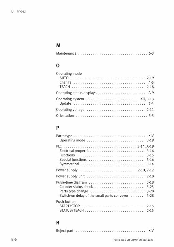
B. Index
B-6 Festo P.BE-CB-COMP-EN en 1102d
M
Maintenance 6-3. . . . . . . . . . . . . . . . . . . . . . . . . . . . . . . . . . . . .
O
Operating modeAUTO 2-19. . . . . . . . . . . . . . . . . . . . . . . . . . . . . . . . . . . . . . .Change 4-5. . . . . . . . . . . . . . . . . . . . . . . . . . . . . . . . . . . . . .TEACH 2-18. . . . . . . . . . . . . . . . . . . . . . . . . . . . . . . . . . . . . .
Operating status displays A-9. . . . . . . . . . . . . . . . . . . . . . . . .
Operating system XII, 3-13. . . . . . . . . . . . . . . . . . . . . . . . . . . .Update 1-4. . . . . . . . . . . . . . . . . . . . . . . . . . . . . . . . . . . . . .
Operating voltage 2-11. . . . . . . . . . . . . . . . . . . . . . . . . . . . . .
Orientation 5-5. . . . . . . . . . . . . . . . . . . . . . . . . . . . . . . . . . . . . .
P
Parts type XIV. . . . . . . . . . . . . . . . . . . . . . . . . . . . . . . . . . . . . .Operating mode 3-19. . . . . . . . . . . . . . . . . . . . . . . . . . . . . .
PLC 3-14, A-19. . . . . . . . . . . . . . . . . . . . . . . . . . . . . . . . . . . . . .Electrical properties 3-16. . . . . . . . . . . . . . . . . . . . . . . . . . .Functions 3-15. . . . . . . . . . . . . . . . . . . . . . . . . . . . . . . . . . .Special functions 3-16. . . . . . . . . . . . . . . . . . . . . . . . . . . . .Symmetrical 3-14. . . . . . . . . . . . . . . . . . . . . . . . . . . . . . . . .
Power supply 2-10, 2-12. . . . . . . . . . . . . . . . . . . . . . . . . . . . . .
Power supply unit 2-10. . . . . . . . . . . . . . . . . . . . . . . . . . . . . .
Pulse-time diagram 3-18. . . . . . . . . . . . . . . . . . . . . . . . . . . . .Counter status check 3-25. . . . . . . . . . . . . . . . . . . . . . . . . .Parts type change 3-20. . . . . . . . . . . . . . . . . . . . . . . . . . . .Switch-on delay of the small parts conveyor 3-28. . . . . . .
Push-buttonSTART/STOP 2-15. . . . . . . . . . . . . . . . . . . . . . . . . . . . . . . . .STATUS/TEACH 2-15. . . . . . . . . . . . . . . . . . . . . . . . . . . . . . .
R
Reject part XIV. . . . . . . . . . . . . . . . . . . . . . . . . . . . . . . . . . . . .

B. Index
B-7Festo P.BE-CB-COMP-EN en 1102d
S
Sample parts XIV, 4-4, 4-9, 5-4. . . . . . . . . . . . . . . . . . . . . . . .
Scatter of characteristics 4-10. . . . . . . . . . . . . . . . . . . . . . . . .
Scatter of features A-14. . . . . . . . . . . . . . . . . . . . . . . . . . . . . .
Scope of delivery VIII. . . . . . . . . . . . . . . . . . . . . . . . . . . . . . . .
SensorExternal 3-16. . . . . . . . . . . . . . . . . . . . . . . . . . . . . . . . . . . . .Selection A-25. . . . . . . . . . . . . . . . . . . . . . . . . . . . . . . . . . . .
Service VIII. . . . . . . . . . . . . . . . . . . . . . . . . . . . . . . . . . . . . . . .
Small parts conveyor 3-7, 3-27. . . . . . . . . . . . . . . . . . . . . . . . .
Software 1-4. . . . . . . . . . . . . . . . . . . . . . . . . . . . . . . . . . . . . . .Download 1-4. . . . . . . . . . . . . . . . . . . . . . . . . . . . . . . . . . . .
Start-up 2-17. . . . . . . . . . . . . . . . . . . . . . . . . . . . . . . . . . . . . . .
START/STOP 2-15, 2-20, A-9. . . . . . . . . . . . . . . . . . . . . . . . . . .
Start/Stop mode 3-17. . . . . . . . . . . . . . . . . . . . . . . . . . . . . . .
STATUS/TEACH 2-15, 2-20, A-9. . . . . . . . . . . . . . . . . . . . . . . . .
Switch-on delay 3-18, 3-27, 3-28. . . . . . . . . . . . . . . . . . . . . . .
Switching off 2-19. . . . . . . . . . . . . . . . . . . . . . . . . . . . . . . . . . .
System parameters 2-13. . . . . . . . . . . . . . . . . . . . . . . . . . . . .
T
Target group VIII. . . . . . . . . . . . . . . . . . . . . . . . . . . . . . . . . . . .
TEACH XIV, 2-18. . . . . . . . . . . . . . . . . . . . . . . . . . . . . . . . . . . . .
Teach data XIV. . . . . . . . . . . . . . . . . . . . . . . . . . . . . . . . . . . . .Evaluate 5-3. . . . . . . . . . . . . . . . . . . . . . . . . . . . . . . . . . . . . .Protect 5-3. . . . . . . . . . . . . . . . . . . . . . . . . . . . . . . . . . . . . . . .
Teach procedure XIV, 1-7, 4-5. . . . . . . . . . . . . . . . . . . . . . . . .Preparing 4-3. . . . . . . . . . . . . . . . . . . . . . . . . . . . . . . . . . . .
Test mode 5-4. . . . . . . . . . . . . . . . . . . . . . . . . . . . . . . . . . . . . .
Test procedure XIV, 1-8, 5-3. . . . . . . . . . . . . . . . . . . . . . . . . . .

B. Index
B-8 Festo P.BE-CB-COMP-EN en 1102d
Tolerance XIV, 5-7, A-12. . . . . . . . . . . . . . . . . . . . . . . . . . . . . .
tool 3-20, A-10. . . . . . . . . . . . . . . . . . . . . . . . . . . . . . . . . . . . . .
Type of errorAmbient fault 2-20, A-5. . . . . . . . . . . . . . . . . . . . . . . . . . . . .Data fault 2-20, A-7. . . . . . . . . . . . . . . . . . . . . . . . . . . . . . . .Hardware fault 2-20, A-7. . . . . . . . . . . . . . . . . . . . . . . . . . . .Recognition fault 2-20, A-6. . . . . . . . . . . . . . . . . . . . . . . . . .
W
Warning 2-20, A-4. . . . . . . . . . . . . . . . . . . . . . . . . . . . . . . . . . .