CHARNLEY - Forsiden |...
16
CHARNLEY ® , THE WORLD’S MOST SUCCESSFUL HIP IMPLANT Surgical Technique CHARNLEY ®
-
Upload
hoangduong -
Category
Documents
-
view
231 -
download
0
Transcript of CHARNLEY - Forsiden |...

CHARNLEY ®,
THE WORLD’S
MOST SUCCESSFUL
HIP IMPLANT
S u r g i c a l T e c h n i q u e
CHARNLEY®

The principles of low frictional
torque arthroplasty laid down by
Sir John Charnley in the early
1950’s, based on the 22.225mm
diameter femoral head, have
proved remarkably reliable.1
Long term results for Charnley®
implants, achieved by surgeons
working in centres worldwide,
continue to set the standard by
which all other implants must
be judged.2
Today’s Charnley® hip is the result
of a thirty year learning curve -
with each new development
setting higher and higher
standards in design, materials and
manufacturing.
A range of twenty six femoral sizes
provides the surgeon with a stem
choice to suit every patient, and
comprehensive instrumentation
designed to assure accuracy,
assists the surgeon to produce
consistent, reliable clinical results.
The Charnley® Total Hip System
offers the surgeon a comprehensive
range of pre-operative planning
templates with 20% magnification.
Pre-operative templating allows the
surgeon to judge the appropriate
position, size and neck offset of the
implant in order to restore the
patient’s normal anatomy.
A radiograph showing the AP view
of the proximal femur, internally
rotated 15 ,̊ provides the most
important information: a level for
the neck resection which will
restore leg length; the appropriate
neck offset for a natural position of
the femoral head; and the
lateral/medial dimensions of the
femoral canal which determine the
overall size of the implant.
The AP view also presents the
position of femur relative to the
bony landmarks of the pelvis, and
Pre-operative planning
the correct anatomical position of
the acetabular component relative
to landmarks such as the tear drop.
The lateral view showing the
amount of femoral bow, helps to
confirm the diameter of the femoral
canal and highlights abnormalities
in this plane which might affect the
position of the implant.
AP view
2
The pre-operative preparation and surgical approach have been described by:Mr MH Stone M Phil FRCS (Ed), Mr D McDonald FRCS and Dr OS Husby MD.
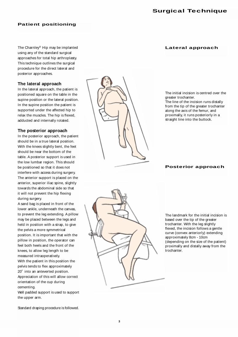
The Charnley® Hip may be implanted
using any of the standard surgical
approaches for total hip arthroplasty.
This technique outlines the surgical
procedure for the direct lateral and
posterior approaches.
The lateral approachIn the lateral approach, the patient is
positioned square on the table in the
supine position or the lateral position.
In the supine position the patient is
supported under the affected hip to
relax the muscles. The hip is flexed,
adducted and internally rotated.
The posterior approachIn the posterior approach, the patient
should be in a true lateral position.
With the knees slightly bent, the feet
should be near the bottom of the
table. A posterior support is used in
the low lumbar region. This should
be positioned so that it does not
interfere with access during surgery.
The anterior support is placed on the
anterior, superior iliac spine, slightly
towards the abdominal side so that
it will not prevent the hip flexing
during surgery.
A sand bag is placed in front of the
lower ankle, underneath the canvas,
to prevent the leg extending. A pillow
may be placed between the legs and
held in position with a strap, to give
the pelvis a more symmetrical
position. It is important that with the
pillow in position, the operator can
feel both heels and the front of the
knees, to allow leg length to be
measured intraoperatively.
With the patient in this position the
pelvis tends to flex approximately
20˚ into an anteverted position.
Appreciation of this will allow correct
orientation of the cup during
cementing.
Well padded support is used to support
the upper arm.
Standard draping procedure is followed.
Patient positioning
Surgical Technique
The landmark for the initial incision is
based over the tip of the greater
trochanter. With the leg slightly
flexed, the incision follows a gentle
curve (convex anteriorly) extending
approximately 8cm - 10cm
(depending on the size of the patient)
proximally and distally away from the
trochanter.
The initial incision is centred over the
greater trochanter.
The line of the incision runs distally
from the tip of the greater trochanter
along the axis of the femur, and
proximally, it runs posteriorly in a
straight line into the buttock.
Lateral approach
Posterior approach
3

With the initial incision made, work
down through the subcutaneous
tissue over the proximal femur to the
fascia lata, which appears at the base
of the wound.
Split the fascia lata distally from the
greater trochanter, in line with its
fibres. The opening is then extended
proximally, in line with the initial
incision. Equal exposure should be
achieved both proximally and distally,
to allow the femur to be fully
visualised and mobilised during
insertion of the prosthesis.
Soft tissue is cleared away and the
sciatic nerve may be identified for
reference during acetabular
preparation.
The skin and fat are divided, clearing
the deep fascia along the length of the
incision.
The deep fascia is opened. Using
blunt dissection, the muscles are split
in line with their fibres.
The Charnley® initial incision
retractor is inserted with the C-Arm
concave towards the head. The
anterior blade is placed on the
musculo tendonous junction of the
deep fascia, and a similar position is
adopted for the posterior blade. The
distal free edge of the trochanteric
bursa is then exposed. A pair of Mayo
scissors is inserted under this free
edge and slid proximally along the
posterior margin of the femur. The
bursa is then lifted, remaining
attached only on its proximal and
anterior side. This exposes the fat of
the short rotator muscles and the free
edge of the gluteus medius muscle.
Position a Charnley® retractor in the
deep fascia layer at the anterior rim of
the abductor muscles and at the
gluteus maximus, and extend the
retractor so that the proximal femur
is exposed.
With the leg adducted, the greater
trochanter is presented into the
centre of the wound.
Using diathermy, incise from the tip of
the greater trochanter through the
anterior third of the tendonous
attachment of the gluteus medius,
cutting around the trochanter to
allow a cuff of tissue for reattachment.
Extend the incision along the line of
the femur toward the quadriceps
muscles. Further exposure is achieved
proximally by splitting the abductor
muscles in line with their fibres.
A plane is developed with the Mayo
scissors deep to the free edge of the
gluteus medius muscle and the
greater trochanter. The anterior blade
of the initial incision retractor is then
inserted into this gap between the
posterior edge of the gluteus medius
and the greater trochanter.
The fat is swept posteriorly off the
short rotators using a swab.
At this point, diathermy should not be
used in close proximity to the sciatic
nerve. The sciatic nerve may be visible
in the depth of the posterior part of
the wound. If not immediately visible,
it may be felt but it is not necessary to
expose the nerve.
Lateral approach
Posterior approach
4

A blunt nosed retractor is placed over
the anterior lip of the joint capsule.
Radially incise the anterior capsule,
and excise the anterior flap.
With the capsule fully excised, the hip
can be dislocated without force.
Release the inferior capsule on the
neck of the femur, taking care to
ensure that the abductor muscles
remain attached to the posterior part
of the femoral neck.
It is important to fully release both
the inferior and posterior capsule so
that the femur can be safely delivered
into the wound without risk of
fracture.
The tendons from piriformis
proximally, superior gemellus, tendon
of obturator internus, inferior
gemellus and quadratus femoris
muscle are now exposed.
The quadratus femoris is left
undisturbed and a stay suture is
passed through the other tendons
several times, using a number 1 vicryl
suture. This is then attached to an
artery forcep.
The tendons of the short rotators,
except for the quadratus femoris, are
then cut with a diathermy point
between the stay suture and the
trochanter. The incision should start
proximally and run parallel to the
sciatic nerve from the tip of the
trochanter to the inferior gemellus
muscle. The leg is then rotated
internally and the line of the cut turns
in an anterior direction toward the
assistant. This exposes the posterior
capsule.
A finger is placed anterior to the
sciatic nerve, between the cut tendons
and the capsule. The incision is
turned into a T-shape by cutting the
capsule anteriorly away from the
operator’s finger.
At this stage it is usually possible to
flex the hip and internally rotate the
femur. The head will dislocate and, as
the knee is brought into adduction,
the neck will come fully into view. It
is often necessary to cut the tight
capsular fibres around the neck of the
femur with diathermy.
Further exposure is achieved by
dividing the abductor muscles in line
with their fibres, using blunt
dissection.
A continuous flap is opened, from the
abductors to the quadriceps. This will
be reattached on completion of the
procedure.
5

Ensure that the femur is presented well into the wound
to provide good access during preparation of the femoral
canal.
Access the femoral canal at the piriformis fossa, using the
Excel™ initiator attached to the ‘T’ handle.
NB. It is important to ensure that the entry point is
positioned laterally and posteriorly to ensure correct
orientation of the stem within the femoral canal. i.e.
the entry point, shaft of initiator and long axis of the
femur are coincident.
Femoral initiation
Entry point to the femur at the piriformis fossa
Accurate positioning of the entry point will avoid implant
malalignment. The aim of stem positioning is to centralise
the stem in both the AP and lateral projections.
Approach through the piriformis fossa leads to neutral AP
and neutral lateral stem positioning within an even cement
mantle.
Entry point posterior and lateral
at the piriformis fossa. Posterior
cortex is resected. Free access is
gained to the femoral canal.
Correctly aligned stem in line
with the long axis of the femur,
allowing for an even cement
mantle.Entry point too anterior
and medial.
Correctly aligned stem Malaligned stem
Correctly aligned stem Malaligned stem
Posterior viewStem aligned centrally in the canal
Posterior viewStem in varus
Correctly aligned stem Malaligned stem
Lateral viewStem aligned centrally in the canal
Lateral viewStem in retroversion and tip against
posterior cortex
Medial viewStem aligned centrally in the canal
Medial viewStem in retroversion and tip against
posterior cortex
6

Prosthesis
catalogue Distal reamernumber Description diameter (mm)
9622-97-000 Flanged 40 12
9622-96-000 Extra Heavy Flanged 40 12
9623-00-000 Roundback 40 12
9623-01-000 Roundback 40 Narrow 11
9623-40-000 Roundback 45 12
9623-43-000 Flanged 45 12
9623-47-000 Extra Heavy Flanged 45 12
9623-49-000 Long Neck 1 12
9623-50-000 Long Neck 1 Extra Heavy 12
9623-54-000 Long Neck 1 Long Stem 12
9623-52-000 Long Neck 2 12
9623-53-000 Long Neck 2 Extra Heavy 12
9623-55-000 Long Neck 2 Long Stem 12
9623-59-000 3/4 Neck 12
9623-60-000 CDH 12
9624-17-000 SNS35 11
9624-22-000 Magnum 40 13
9624-23-000 Magnum 45 14
9624-24-000 CD Extra Small 11
9624-18-000 Straight Thick Stem 12
9623-46-000 Flanged 35 12
9624-16-000 Flanged 40 Long Stem 12
9624-20-000 Extra Heavy Flanged 40 Long Stem 12
9623-62-000 Extra Small 11
Reaming guide
Attach the Excel™ canal probe to the ‘T’ handle and
introduce the probe into the femoral canal in line with
the femur.
Maintain a neutral orientation and ensure that the probe
does not impinge on the entry hole. If the entry point is
correct, the probe should pass down the femur easily.
Introduce the first reamer and begin to enlarge the cavity,
progressively increasing the size of reamer until the
reaming diameter corresponds to the predetermined
implant size (see table).
Canal reaming
7

Excise the remaining capsule from around the
acetabulum. Ensure that the rim and bed of the
acetabulum are clear of soft tissues and osteophytes using
the Charnley® ring curette and Charnley® small curette.
Beginning with the smallest diameter reamer,
progressively ream away the remaining soft tissues in the
acetabular bed. Remove all remaining articular cartilage
and any medial osteophytes until healthy, bleeding
subchondral bone is exposed and a symmetrical,
hemispherical dome is achieved. The reamer should be
introduced in 45˚ of abduction and 15˚ of anteversion.
NB. If the posterior approach is employed, it should be
remembered that this position puts the pelvis in
approximately 20˚of anteversion which must be
compensated for during acetabular reaming and cup
placement.
Acetabular preparation
The level of the neck resection is determined during
preoperative templating. The cut will be approximately
1cm - 2cm above the lesser trochanter or distal to the
articular margin. Centre the neck resection guide along
the neutral axis of the femur and mark the 45˚ resection
line using diathermy.
Perform the osteotomy using an oscillating saw, taking
care to maintain the correct angle. If the posterior
approach is being used, two Trethowan retractors are
placed around the femoral neck at this stage.
Cut the ligamentum teres and remove the femoral head.
If a bone plug is to be used in the distal femur to restrict
the cement, this may now be taken from the exposed
cancellous bone of the proximal femur.
Femoral neck resection
8

Drill multiple holes in the roof of the acetabulum using
the collared Charnley® acetabular preparation drill to
encourage extensive intrusion of the cement into the
interstices of the bone.
NB. Care should be taken to avoid the medial wall of the
acetabulum. This is a triangle of bone based on the
transverse ligament.
Smooth the edges of the drill holes and remove the debris
using a small curette.
Use the spoon to feel for any cysts which may not have
been revealed by radiological examination.
Attach the phantom cup and trial flange to the cup
introducer and check the size of the acetabulum. Trim the
rim of the trial flange so that it just fits within the rim of
the acetabulum.
Using the trial as a guide, cut the flange of the definitive
cup to match.
Lavage and clear the acetabulum of debris.
Acetabular sizing
9

Using the leading edge of the anteversion osteotome
positioned laterally toward the greater trochanter, enlarge
the entry point to the femoral canal and establish 10˚- 15˚
of anteversion for broach alignment.
Reverse the osteotome and extend the entry point
medially toward the lesser trochanter. Remove a wedge of
cancellous bone approximately the same size and shape
as the proximal section of the prosthesis.
Femoral canal preparation
Attach the cup to the cup introducer. Introduce the
cement into the acetabular bed and insert the cup.
The cement should be fully contained behind the rim of
the cup, and the rim well supported by the cement.
Align the shaft of the introducer with the anterior
superior iliac spine and rotate the handle posteriorly to
give 10˚ - 15˚ of anteversion.
(Using the posterior approach, anteversion of the pelvis
requires the cup holder to be orientated at approximately
30˚ - 35˚ of anteversion relative to the long axis of the
patient.)
Locate the cup pusher on the back of the cup introducer
and pressurise the cement. Once the cement has begun to
polymerise, the cup pusher can be applied directly to the
cup and pressure maintained until polymerisation is
complete.
The rim of the acetabulum should be checked for any
remaining osteophytes and cement debris which might
cause impingement.
To protect the cup, cover it with a clean swab. Attention
may now be turned to the femur.
Cup implantation
10˚ of anteversion
Long axis of the patient
Shaft of the introducer
parallel to the superior and
inferior illiac spines.
10

When the final broach is seated at the resection line,
fit the trial head onto the neck of the broach and reduce
the hip.
Check for impingement and joint stability through
adduction, rotation and flexion.
Remove the trial head and re-engage the in line broach
handle to extract the broach.
Introduce the cement restrictor and ensure that it is firmly
seated in the femoral canal at the depth indicated by the
size of the definitive implant (see table overleaf).
Using a bone brush and irrigation, ensure that the femoral
canal is clear of blood and loose debris.
Trial reduction
Attach a broach, smaller than that determined during
preoperative templating, to the in line broach handle.
With the broach parallel to the long axis of the femur and
at right angles to the tibia, pass the broach down the
canal in neutral orientation, with 10˚- 15˚ of anteversion.
To avoid varus alignment with the femoral axis, position
the broach laterally toward the greater trochanter.
Progressively increase the size of broach until a cavity is
prepared which matches the size planned during
pre-operative templating.
Broaching
11

Attach the definitive femoral implant, with its cover in
place, to the Charnley® introducer.
Insert the cement, filling the femoral canal and
pressurise the cement. (Effective pressurisation should
result in the extrusion of blood through the cortex at the
rim of the proximal femur.)
Introduce the implant, in line with the femoral axis i.e.
down the piriformis fossa. Remove the implant cover and
maintain pressure on the femoral head, using the head
pusher, until polymerisation is complete.
Remove all excess cement, taking care not to scratch the
femoral head, and irrigate thoroughly to clear away any
remaining debris from the joint.
Carry out a final reduction to check joint stability function.
Introduce the first drain into the joint and reattach the
tendonous tissue below the flap of the abductor muscles.
Place the second drain behind the trochanter and close
the wound.
In the posterior approach, after the first drain has been
introduced the short rotator muscles are reattached to the
posterior edge of the gluteus medius tendon.
Stem implantation
Cement Cement
Prosthesis Broach restrictor restrictor
description description size depth
Flanged 40 F40 12 135
Extra Heavy Flanged 40 F40EH 12 135
Roundback 40 RB40 12 135
Roundback 40 Narrow RB40N 11 135
Roundback 45 RB45 12 135
Flanged 45 F45 12 135
Extra Heavy Flanged 45 F45EH 12 135
Long Neck 1 LN1 12 135
Long Neck 1 Extra Heavy LN1EH 12 140
Long Neck 2 L2 12 135
Long Neck 2 Extra Heavy LN2EH 12 135
Long Neck 1 Long Stem LN1LS 12 200
Long Neck 2 Long Stem LN2LS 12 205
3/4 Neck 3/4N 12 115
CDH CDH 12 130
SNS35 SNS35 11 135
Magnum 40 M40 13 135
Magnum 45 M45 14 155
CDH Extra Small CDHES 11 130
Standard Thick Stem SNS35 11 135
Resection Stem N/A
15” Stem 40 N/A
Flanged 35 SNS35 11 135
Flanged 40 Long Stem FL40 12 190
Extra Heavy Flanged 40
Long Stem EHFL40 12 190
Extra Small CDHES 11 140
Cement restrictor depths
❊
These measurements are taken from the medial edge of the neckosteotomy and allow for 20mm of cement distal to the tip of theprosthesis. If a bone block is to be used, this distance may be variedaccording to surgeon preference.
In these instances, increased reaming depth is required to accommodate the longer stem length.
The recommended broach should be used as a rasp to prepare thefemur and a trial implant is used to assess joint function and stability.
Dimensions in millimetres.
❊
✶
✪
✪
✪
✪
✪
✶
✶
✶
12


Acetabular Implants
Charnley®
9650-22-040 Charnley® Std Cup 22.225/40
9650-22-043 Charnley® Std Cup 22.225/43
9650-22-047 Charnley® Std Cup 22.225/47
9650-22-050 Charnley® Std Cup 22.225/50
9650-22-053 Charnley® Std Cup 22.225/53
9651-22-038 Charnley® LPW Cup 22.225/38
9651-22-040 Charnley® LPW Cup 22.225/40
9651-22-043 Charnley® LPW Cup 22.225/43
9651-22-047 Charnley® LPW Cup 22.225/47
9651-22-050 Charnley® LPW Cup 22.225/50
9651-22-053 Charnley® LPW Cup 22.225/53
9652-22-040 Charnley® Flanged Cup 22.225/40
9652-22-043 Charnley® Flanged Cup 22.225/43
9652-22-047 Charnley® Flanged Cup 22.225/47
9652-22-050 Charnley® Flanged Cup 22.225/50
9652-22-053 Charnley® Flanged Cup 22.225/53
9623-69-000 Charnley® Flanged Cup Std Small
9623-23-000 Charnley® Flanged Cup Std Large
9623-80-000 Charnley® Flanged Cup Offset Bore
9653-22-040 Charnley® Ogee® Cup 22.225/40
9653-22-043 Charnley® Ogee® Cup 22.225/43
9653-22-047 Charnley® Ogee® Cup 22.225/47
9653-22-050 Charnley® Ogee® Cup 22.225/50
9653-22-053 Charnley® Ogee® Cup 22.225/53
9624-10-000 Charnley® Ogee® Cup Std Small
9624-09-000 Charnley® Ogee® Cup Std Large
Acetabular Instruments
2440-30-000 Grater Shaft with Hudson Fitting
2440-38-000 Acetabular Reamer 38mm
2440-40-000 Acetabular Reamer 40mm
2440-42-000 Acetabular Reamer 42mm
2440-44-000 Acetabular Reamer 44mm
2440-46-000 Acetabular Reamer 46mm
2440-48-000 Acetabular Reamer 48mm
2440-50-000 Acetabular Reamer 50mm
2440-52-000 Acetabular Reamer 52mm
2440-54-000 Acetabular Reamer 54mm
2440-56-000 Acetabular Reamer 56mm
2440-58-000 Acetabular Reamer 58mm
2440-60-000 Acetabular Reamer 60mm
9626-29-000 Acetabular Prep Drill
9626-30-000 Cup Introducer 22.225mm
9626-00-000 Cup Trial 40mm
9626-01-000 Cup Trial 43mm
9626-02-000 Cup Trial 47mm
9626-03-000 Cup Trial 50mm
9626-05-000 Cup Trial 53mm
9622-41-000 Trimming Scissors
2015-24-000 Cup Pusher Handle
9601-18-000 Cup Pusher Head 22.225mm
9628-00-000 Cemented Acetabular Instrument Tray
9628-02-000 Cemented Acetabular Templates
13

14
Charnley® Base BroachingInstrument Set
Base Tray
9624-63-000 Charnley® Tray Base and Lid
9620-40-000 Charnley® Neck Osteotomy Guide
2522-00-506 Elite™ In-Line Broach Handle
9626-14-000 Elite™ Femoral Prosthesis Holder
9626-15-000 Elite Trial Femoral Head 22.225 Std
9629-01-000 Charnley®/Elite™ Broach RB40 N
9629-02-000 Charnley®/Elite™ Broach RB40
9629-03-000 Charnley® /Elite™ Broach FL40
9629-04-000 Charnley®/Elite™ Broach FL40 EH
9629-06-000 Charnley®/Elite™ Broach LN1
9625-82-000 Charnley®/Elite™ Broach RB45
9625-83-000 Charnley®/Elite™ Broach FL45
9625-84-000 Charnley®/Elite™ Broach FL45 EH
Charnley® Excel™ FemoralInstrument Set
Top Tray
9624-65-000 Charnley® Tray Excel™ Insert
9620-45-000 Charnley® Curette Small
9620-46-000 Charnley® Curette Medium
9620-47-000 Charnley® Curette Large
9622-72-000 Charnley® Ring Curette
2001-42-000 Excel™ T Handle
2001-43-000 Excel™ IM Initiator
2354-10-000 Muller Awl Reamer with Hudson End
2105-12-000 Canal Reamer 10
2105-14-000 Canal Reamer 11
2105-15-000 Canal Reamer 12
2105-16-000 Canal Reamer 13
2002-25-000 Anteversion Osteotome Medium
2001-65-000 Excel™ Femoral Head Impactor
Alternative Top Tray Instrument Set
Charnley® BroachingInstrument Set
Top Tray
9624-64-000 Charnley® Tray Broaching Insert
9629-00-000 Charnley®/Elite™ Broach SNS 35
9629-05-000 Charnley®/Elite™ Broach Magnum 40
9629-07-000 Charnley®/Elite™ Broach LN1 EH
9629-08-000 Charnley®/Elite™ Broach LN1 LS
9629-09-000 Charnley®/Elite™ Broach LN2
9629-10-000 Charnley®/Elite™ Broach LN2 EH
9629-11-000 Charnley®/Elite™ Broach LN2 LS
9629-12-000 Charnley®/Elite™ Broach CDH
Extra Small
9629-13-000 Charnley®/Elite™ Broach CDH
9629-14-000 Charnley®/Elite™ Broach 3/4 Neck
9625-85-000 Charnley®/Elite™ Broach Magnum 45
9611-33-000 Restrictor Trial Introducer
5460-30-000 Cement Restrictor Trial 1
5460-32-000 Cement Restrictor Trial 2
5460-34-000 Cement Restrictor Trial 3
5460-36-000 Cement Restrictor Trial 4
5460-38-000 Cement Restrictor Trial 5
5460-40-000 Cement Restrictor Trial 6
5460-42-000 Cement Restrictor Trial 7
Femoral Implants
9622-96-000 Charnley® Extra Heavy Flanged 40
9622-97-000 Charnley® Flanged 40
9623-00-000 Charnley® Roundback 40
9623-01-000 Charnley® Roundback 40 Narrow
9623-40-000 Charnley® Roundback 45
9623-43-000 Charnley® Flanged 45
9623-46-000 Charnley® Flanged 35
9623-47-000 Charnley® Extra Heavy Flanged 45
9623-49-000 Charnley® Long Neck 1
9623-50-000 Charnley® Long Neck 1 Extra Heavy
9623-52-000 Charnley® Long Neck 2
9623-53-000 Charnley® Long Neck 2 Extra Heavy
9623-54-000 Charnley® Long Neck 1 Long Stem
9623-55-000 Charnley® Long Neck 2 Long Stem
9623-59-000 Charnley® 3/4 Neck
9623-60-000 Charnley® CDH
9623-62-000 Charnley® Extra Small
9623-63-000 Charnley® 15” Stem 40
9623-64-000 Charnley® Resection Stem
9624-16-000 Charnley® Flanged 40 Long Stem
9624-17-000 Charnley® SNS 35
9624-18-000 Charnley® Straight Thick Stem 35
9624-20-000 Charnley® Extra Heavy Flanged 40 Long Stem
9624-22-000 Charnley® Magnum 40
9624-23-000 Charnley® Magnum 45
9624-24-000 Charnley® CDH Extra Small
5460-10-000 Cement Restrictor Size 1
5460-12-000 Cement Restrictor Size 2
5460-14-000 Cement Restrictor Size 3
5460-16-000 Cement Restrictor Size 4
5460-18-000 Cement Restrictor Size 5
5460-20-000 Cement Restrictor Size 6
5460-22-000 Cement Restrictor Size 7
Ordering Information

DePuy International LtdSt Anthony’s RoadLeeds LS11 8DTEnglandTelephone: +44 (113) 270 0461Fax: +44 (113) 272 4101
Cat No: 9061-79-000
Charnley® and Ogee® are registered trademarks and Elite™ is a trademark of DePuy International Ltd. Excel™ is a trademark of DePuy Orthopaedics, Inc.
© 2003 DePuy International Limited. All rights reserved.
References:
1. Kabo MJ, Gebhard J, Loren G, Amstutz H. In Vivo Wear of Polyethylene
Acetabular Components. J Bone Joint Surg (Br), 75-B, 254-8, 1993.
2. Kavanagh B, Wallrichs S, Dewitz M, Berry D, Currier B, Ilstrup D,
Coventry M. Charnley Low Friction Arthroplasty of the Hip. J of Arthrop,
9, No 3, 1994.
0086
This publication is not intended for distribution in the USA