Charger 2 Damper™ - servicearchive.sram.com · Remove the rebound adjuster knob. Place an oil pan...
31
GEN.0000000005353 Rev C © 2018 SRAM, LLC Charger 2 Damper™ Upgrade Kit service manual
Transcript of Charger 2 Damper™ - servicearchive.sram.com · Remove the rebound adjuster knob. Place an oil pan...
GEN.0000000005353 Rev C© 2018 SRAM, LLC
Charger 2 Damper™Upgrade Kit
s e r v i c em a n u a l
SRAM® LLC WARRANTYEXTENT OF LIMITED WARRANTY
Except as otherwise set forth herein, SRAM warrants its products to be free from defects in materials or workmanship for a period of two years after original purchase. This warranty only applies to the original owner and is not transferable. Claims under this warranty must be made through the retailer where the bicycle or the SRAM component was purchased. Original proof of purchase is required. Except as described herein, SRAM makes no other warranties, guaranties, or representations of any type (express or implied), and all warranties (including any implied warranties of reasonable care, merchantibility, or fitness for a particular purpose) are hereby disclaimed.
LOCAL LAW
This warranty statement gives the customer specific legal rights. The customer may also have other rights which vary from state to state (USA), from province to province (Canada), and from country to country elsewhere in the world.
To the extent that this warranty statement is inconsistent with the local law, this warranty shall be deemed modified to be consistent with such law, under such local law, certain disclaimers and limitations of this warranty statement may apply to the customer. For example, some states in the United States of America, as well as some governments outside of the United States (including provinces in Canada) may:
Preclude the disclaimers and limitations of this warranty statement from limiting the statutory rights of the consumer (e.g. United Kingdom).
Otherwise restrict the ability of a manufacturer to enforce such disclaimers or limitations.
For Australian customers:
This SRAM limited warranty is provided in Australia by SRAM LLC, 1000 W. Fulton Market, 4th Floor, Chicago, IL, 60607, USA. To make a warranty claim please contact the retailer from whom you purchased this SRAM product. Alternatively, you may make a claim by contacting SRAM Australia, 6 Marco Court, Rowville 3178, Australia. For valid claims SRAM will, at its option, either repair or replace your SRAM product. Any expenses incurred in making the warranty claim are your responsibility. The benefits given by this warranty are additional to other rights and remedies that you may have under laws relating to our products. Our goods come with guarantees that cannot be excluded under the Australian Consumer Law. You are entitled to a replacement or refund for a major failure and for compensation for any other reasonably foreseeable loss or damage. You are also entitled to have the goods repaired or replaced if the goods fail to be of acceptable quality and the failure does not amount to a major failure.
LIMITATIONS OF LIABILITY
To the extent allowed by local law, except for the obligations specifically set forth in this warranty statement, in no event shall SRAM or its third party suppliers be liable for direct, indirect, special, incidental, or consequential damages.
LIMITATIONS OF WARRANTY
This warranty does not apply to products that have been incorrectly installed and/or adjusted according to the respective SRAM user manual. The SRAM user manuals can be found online at sram.com, rockshox.com, avidbike.com, truvativ.com, or zipp.com.
This warranty does not apply to damage to the product caused by a crash, impact, abuse of the product, non-compliance with manufacturers specifications of usage or any other circumstances in which the product has been subjected to forces or loads beyond its design.
This warranty does not apply when the product has been modified, including, but not limited to any attempt to open or repair any electronic and electronic related components, including the motor, controller, battery packs, wiring harnesses, switches, and chargers.
This warranty does not apply when the serial number or production code has been deliberately altered, defaced or removed.
This warranty does not apply to normal wear and tear. Wear and tear parts are subject to damage as a result of normal use, failure to service according to SRAM recommendations and/or riding or installation in conditions or applications other than recommended.
Wear and tear parts are identified as:
Dust sealsBushingsAir sealing o-ringsGlide ringsRubber moving partsFoam ringsRear shock mounting
hardware and main sealsUpper tubes (stanchions)
Stripped threads/bolts (aluminium, titanium, magnesium or steel)
Brake sleevesBrake padsChainsSprocketsCassettesShifter and brake cables
(inner and outer)
Handlebar gripsShifter gripsJockey wheelsDisc brake rotorsWheel braking surfacesBottomout padsBearingsBearing racesPawls
Transmission gearsSpokesFree hubsAero bar padsCorrosionToolsMotorsBatteries
Notwithstanding anything else set forth herein, the battery pack and charger warranty does not include damage from power surges, use of improper charger, improper maintenance, or such other misuse.
This warranty shall not cover damages caused by the use of parts of different manufacturers.
This warranty shall not cover damages caused by the use of parts that are not compatible, suitable and/or authorised by SRAM for use with SRAM components.
This warranty shall not cover damages resulting from commercial (rental) use.

SAFETY FIRST!We care about YOU. Please, always wear your safety glasses and protective gloves when servicing RockShox® products.
Protect yourself! Wear your safety gear!

TABLE OF CONTENTSROCKSHOX® DAMPER UPGRADE KIT INSTALLATION .................................................................................................................................5
PART PREPARATION .......................................................................................................................................................................................................................................5SERVICE PROCEDURES .................................................................................................................................................................................................................................5COMPATIBILITY ................................................................................................................................................................................................................................................6PARTS, TOOLS, AND SUPPLIES ..................................................................................................................................................................................................................7
LOWER LEG REMOVAL .......................................................................................................................................................................................8
DAMPER REMOVAL ............................................................................................................................................................................................11MOTION CONTROL™ DAMPER REMOVAL ............................................................................................................................................................................................... 11CHARGER 2 DAMPER™ REMOVAL ............................................................................................................................................................................................................ 14CHARGER DAMPER™ REMOVAL................................................................................................................................................................................................................ 17BOXXER® CHARGER DAMPER RC REMOVAL ...................................................................................................................................................................................... 19
DAMPER UPGRADE INSTALLATION ............................................................................................................................................................. 20SID®/REBA®/BLUTO™ CHARGER 2 DAMPER INSTALLATION ..........................................................................................................................................................20PIKE®/REVELATION™/LYRIK™/YARI™ CHARGER 2 DAMPER INSTALLATION .............................................................................................................................. 22BOXXER® CHARGER DAMPER RC2 INSTALLATION ......................................................................................................................................................................... 26
LOWER LEG INSTALLATION ............................................................................................................................................................................ 28

5RockShox® Damper Upgrade Kit Installation
R o c k S h o x ® D a m p e r U p g r a d e K i t I n s t a l l a t i o nWe recommend that you have your RockShox suspension serviced by a qualified bicycle mechanic. Servicing RockShox suspension requires knowledge of suspension components, as well as the use of specialized tools and lubricants/fluids. Failure to follow the procedures outlined in this service manual may cause damage to your component and void the warranty.
Visit www.sram.com/service for the latest RockShox Spare Parts catalog and technical information. For order information, please contact your local SRAM® distributor or dealer.
Information contained in this publication is subject to change at any time without prior notice.
Your product's appearance may differ from the pictures contained in this publication.
For recycling and environmental compliance information, please visit www.sram.com/company/environment.
P a r t P r e p a r a t i o nRemove the component from the bicycle before service.
Disconnect and remove the remote cable from the fork, if applicable. For additional information about RockShox remotes, user manuals are available at www.sram.com/service.
Clean the exterior of the product with mild soap and water to avoid contamination of internal sealing part surfaces.
S e r v i c e P r o c e d u r e sThe following procedures should be performed throughout service, unless otherwise specified.
Clean the part with RockShox Suspension Cleaner or isopropyl alcohol and a clean, lint-free shop towel. For hard to reach places (e.g. upper tube, lower leg), wrap a clean, lint-free shop towel rag around a non-metallic dowel to clean the inside.
Clean the sealing surface on the part and inspect it for scratches.

6Compatibility
C o m p a t i b i l i t yNOTICE
Damper top caps and upper tube thread pitches may vary; consult the chart to verify compatibility before damper upgrade installation.Installation of an incompatible damper top cap will damage the upper tube and damper top cap threads. If you are unsure what model year or generation you have, contact your local SRAM® distributor or dealer.
32 mm Chassis
Fork Model Year Generation Max Travel (mm) Wheel Size (in) Compression Adj. Upgrade Kit
SID®
2012-2016 A2-A4
120
27.5 & 29 Boost™ & Non-Boost
Crown 00.4018.783.003
Remote 00.4018.783.011
2017+ B1+Crown 00.4018.783.009
Remote 00.4018.783.010
Reba® 2012-2017+ A1-A5Crown 00.4018.783.003
Remote 00.4018.783.011
Bluto™ 2015+ A1+ 26Crown 00.4018.783.003
Remote 00.4018.783.011
35 mm Chassis
Fork Model Year Generation Max Travel (mm) Wheel Size (in) Compression Adj. Upgrade Kit
BoXXer® 2019+ C1 200 27.5 & 29 Boost Crown 00.4018.783.025
PIKE®
2014-2017
A1-A2
160
26Crown 00.4018.783.021
Remote 00.4018.783.012
27.5Crown 00.4018.783.022
Remote 00.4018.783.013
29Crown 00.4018.783.023
Remote 00.4018.783.014
27.5 BoostCrown 00.4018.783.015
Remote 00.4018.783.016
29 BoostCrown 00.4018.783.017
Remote 00.4018.783.018
2016+ 29+Crown 00.4018.783.019
Remote 00.4018.783.020
2018+ B1+ 27.5 & 29 Boost
Crown 00.4018.783.015
Remote 00.4018.783.016
Revelation™Crown 00.4018.783.015
Remote 00.4018.783.016
Lyrik™
2010-2016 A1-B1
180
26 Crown 00.4018.783.002
2016+
B1+
27.5 & 29 Boost & Non-Boost
Crown 00.4018.783.019
Remote 00.4018.783.020
Crown 00.4018.783.024
Yari™ A1+Crown 00.4018.783.019
Remote 00.4018.783.020

7Parts, Tools, and Supplies
P a r t s , T o o l s , a n d S u p p l i e sParts
• CHARGER 2 DAMPER™ RLC Remote 120 max travel
• CHARGER 2 DAMPER RLC Crown 120 max travel
• CHARGER 2 DAMPER RCT Remote
• CHARGER 2 DAMPER RCT3 Crown
• CHARGER 2 DAMPER RC2 Crown
• CHARGER 2 DAMPER RC2 Crown BoXXer®
Safety and Protection Supplies
• Apron
• Clean, lint-free shop towels
• Nitrile gloves
• Oil pan
• Safety glasses
Lubricants and Fluids
• SRAM® Butter grease
• RockShox® Suspension Cleaner or isopropyl alcohol
• RockShox 0w-30 Suspension Oil (PIKE®/Revelation™/Lyrik™/Yari™/BoXXer)
• RockShox 15wt Suspension Oil (SID®/Reba®/Bluto™)
Bicycle Tools
• Bicycle work stand
• Shock pump
Common Tools
• Cassette lockring tool or RockShox Top Cap/Cassette Tool (3/8"/24 mm)
• Hex bit sockets: 2 mm, 2.5 mm, 5 mm
• Hex wrenches: 1.5 mm, 2 mm, 2.5 mm, 4 mm, 5 mm
• Internal retaining ring pliers
• Long plastic or wooden dowel
• Open end wrench: 10 mm, 24 mm (XLoc™)
• Pick
• Rubber or plastic mallet
• Socket wrench: 6 mm, 24 mm, 30 mm
• Torque wrench
SAFETY INSTRUCTIONSAlways wear safety glasses and nitrile gloves when working with suspension oil.
Place an oil pan on the floor underneath the area where you will be working on the fork.

8Lower Leg Removal
L o w e r L e g R e m o v a lThe procedure for removing the lower leg is similar across RockShox® front suspension forks. Your fork's knobs, bolts, and chassis may appear different from the pictures. Consult your fork's service manual for more detailed instructions.
Loosen the rebound adjuster knob screw, if present.
Remove the rebound adjuster knob.
Place an oil pan beneath the fork to catch the draining oil.
Loosen both bottom bolts 3 to 4 turns.
BoXXer®: Loosen the damper side bottom bolt 3 to 4 turns.
1
2.5 mm
1
Spring Side
Damper Side2
5 mm Damper Side
9Lower Leg Removal
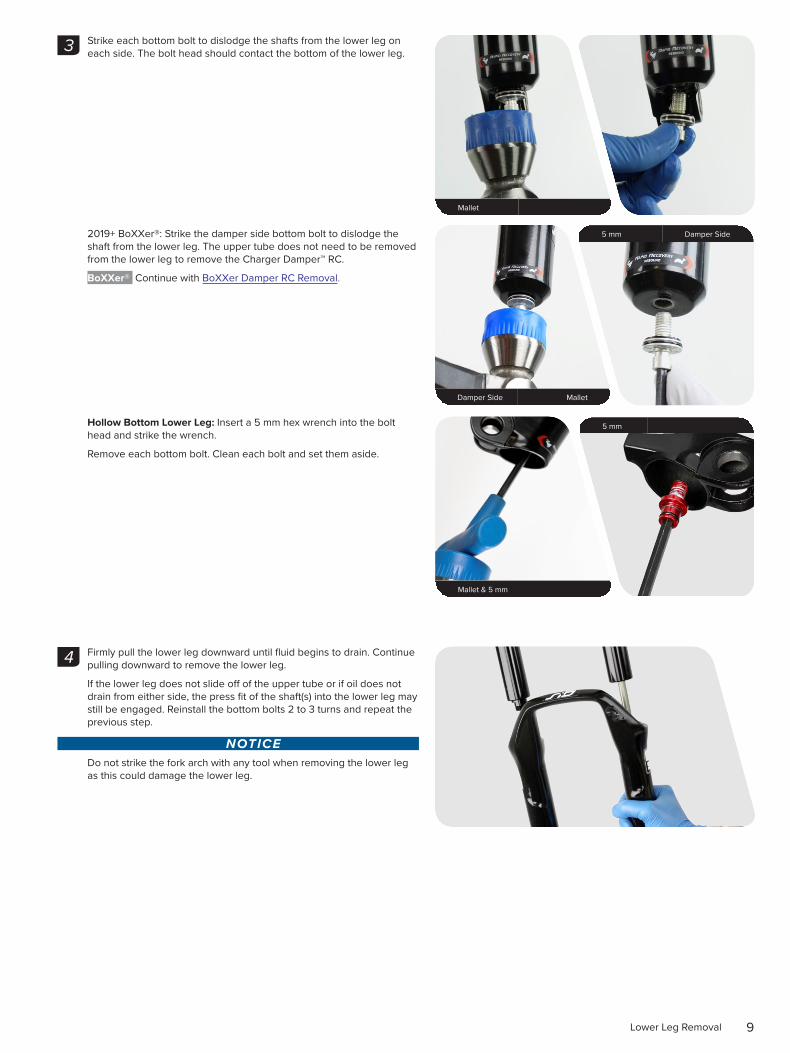
Strike each bottom bolt to dislodge the shafts from the lower leg on each side. The bolt head should contact the bottom of the lower leg.
2019+ BoXXer®: Strike the damper side bottom bolt to dislodge the shaft from the lower leg. The upper tube does not need to be removed from the lower leg to remove the Charger Damper™ RC.
BoXXer® Continue with BoXXer Damper RC Removal.
Hollow Bottom Lower Leg: Insert a 5 mm hex wrench into the bolt head and strike the wrench.
Remove each bottom bolt. Clean each bolt and set them aside.
Firmly pull the lower leg downward until fluid begins to drain. Continue pulling downward to remove the lower leg.
If the lower leg does not slide off of the upper tube or if oil does not drain from either side, the press fit of the shaft(s) into the lower leg may still be engaged. Reinstall the bottom bolts 2 to 3 turns and repeat the previous step.
NOTICEDo not strike the fork arch with any tool when removing the lower leg as this could damage the lower leg.
Mallet
3
Damper Side Mallet
5 mm Damper Side
Mallet & 5 mm
5 mm
4

10Lower Leg Removal
Clean the inside and outside of the lower leg. Clean the wiper seals.
Set the lower leg aside.
SID®/Reba®/Bluto™ Continue with Motion Control or Charger 2 Damper Removal.
PIKE®/Revelation™/Lyrik™/Yari™ Continue with Motion Control, Charger Damper, or Charger 2 Damper Removal.
5

11Damper Removal
D a m p e r R e m o v a l
M o t i o n C o n t r o l ™ D a m p e r R e m o v a l
The procedure for removing the damper is similar across RockShox® front suspension forks. Your fork's knobs, bolts, and damper may appear different from the pictures. Consult your fork's service manual for more detailed instructions.
Crown: Rotate the adjuster knob to the open position.
Crown: Remove the retention screw, nut (some models), and compression adjuster knob(s).
1
2
2 or 2.5 mm Crown
Crown
1.5 mm
10 mm

12Motion Control™ Damper Removal
Remote: Remove the retention screw and cable spool. Loosen the remote cable stop collar clamping bolt, and remove it.
Remove the lower remote spool, if present.
Unthread the compression damper top cap.
Remove the compression damper by pulling up firmly and slowly, while gently rotating the damper in a circular motion.
NOTICEDo not force the damper out of the upper tube if there is resistance. This can cause separation of the piston from the damper tube.
XLoc™ Remote: Press the XLoc remote button to the compressed (open) position. Unthread the compression damper.
Remove the compression damper by pulling up firmly and slowly, while gently rotating the damper in a circular motion.
NOTICEDo not force the damper out of the upper tube if there is resistance. This can cause separation of the piston from the damper tube.
3
2.5 mm Remote
2 mm Remote
Remote
4
24 mm
24 mm XX™

13Motion Control™ Damper Removal
Remove the fork from the work stand and pour the suspension oil into an oil pan.
Clamp the fork into the work stand.
Thread the bottom bolt onto the rebound damper shaft and push the shaft into the upper tube.
Remove the retaining ring.
Pull the rebound shaft to full extension. Remove the rebound damper and seal head. Remove the bottom bolt, if installed.
SID®/Reba®/Bluto™ Continue with SID/Reba/Bluto Charger 2 Damper Installation
PIKE®/Revelation™/Lyrik™/Yari™ Continue with Pike/Revelation/Lyrik/Yari Charger 2 Damper Installation.
5
6
Pick
Retaining Ring Pliers7
8

14Charger 2 Damper™ Removal
C h a r g e r 2 D a m p e r ™ R e m o v a l
The procedure for removing the damper is similar across RockShox® front suspension forks. Your fork's knobs, bolts, and damper may appear different from the pictures. Consult your fork's service manual for more detailed instructions.
Crown adjust: Turn the lockout adjuster knob to the open, unlocked position.
Crown adjust: Remove the knob retaining screw.
1
RLC
RL / RC
RCT3
RC2
2
2.5 mm RLC
2 mm RL
2 mm RC2 / RCT3
2 mm RC

15Charger 2 Damper™ Removal
Remove the low speed compression and lockout knob from the top cap.
Remove the compression mode adjuster knob.
Remote: Remove the low speed compression adjuster knob and spool assembly. Remove the cable stop collar. Keep the parts together and set aside.
Remove the cable stop collar. Remove the spool.
RLC
RC 2/ RCT3
RC2 / RCT3
RC / RL
3
2.5 mm / 2 mm RLC R / RCT R
2 mm RLC R / RCT R
2 mm RL R / RC R
2 mm RL R / RC R
16Charger 2 Damper™ Removal
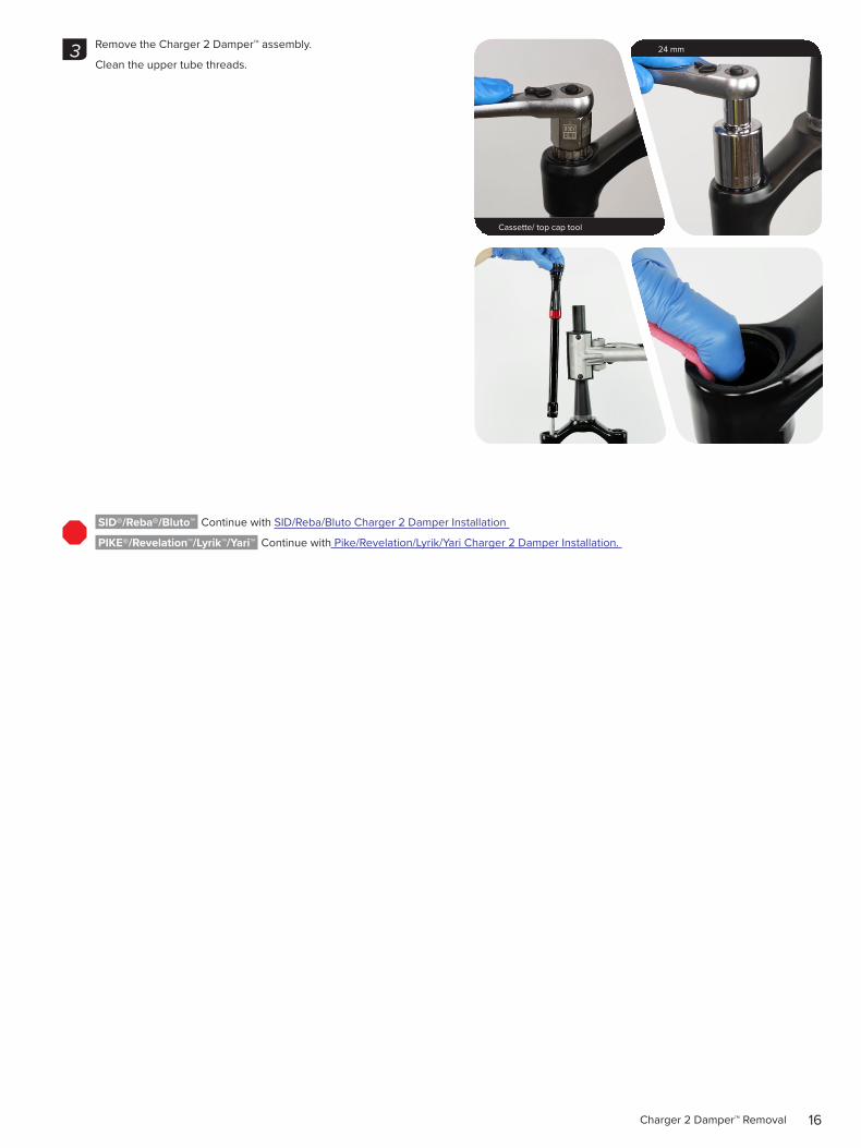
Remove the Charger 2 Damper™ assembly.
Clean the upper tube threads.
SID®/Reba®/Bluto™ Continue with SID/Reba/Bluto Charger 2 Damper Installation
PIKE®/Revelation™/Lyrik™/Yari™ Continue with Pike/Revelation/Lyrik/Yari Charger 2 Damper Installation.
Cassette/ top cap tool
24 mm3

17Charger Damper™ Removal
C h a r g e r D a m p e r ™ R e m o v a l
The procedure for removing the damper is similar across RockShox® front suspension forks. Your fork's knobs, bolts, and damper may appear different from the pictures. Consult your fork's service manual for more detailed instructions.
Crown: Turn the lockout adjuster knob to the open, unlocked position.
Crown: Remove the knob retaining screw and remove the compression adjuster knob.
RCT3 Only: Remove the low speed adjuster knob screw. Remove the low speed adjuster knob.
Remove the knob retaining nut. Remove the compression adjuster knob.
1
Crown
2
2 or 2.5 mm
4 mm
2 mm RCT3
6 mm RCT3

18Charger Damper™ Removal
Remove the Charger Damper™ assembly.
Clean the upper tube threads.
PIKE®/Revelation™/Lyrik™/Yari™ Continue with Pike/Revelation/Lyrik/Yari Charger 2 Damper Installation.
Top Cap / Cassette Tool
24 mm or 30 mm3

19BoXXer® Charger Damper™ RC Removal
B o X X e r ® C h a r g e r D a m p e r ™ R C R e m o v a l
Turn the compression adjuster knob counter-clockwise, to the full open position, until it stops.
Remove the retaining screw and remove the knob.
Unthread the damper top cap and remove the Charger Damper™ RC assembly.
Clean the upper tube threads.
NOTICETo prevent scratching the rebound damper shaft, use your fingers to protect and guide the shaft as you remove the Charger Damper RC from the upper tube.
BoXXer® Continue with BoXXer Charger Damper™ RC2 Installation
1
2.5 mm
2
Top Cap / Cassette Tool
3

20Damper Upgrade Installation
D a m p e r U p g r a d e I n s t a l l a t i o n
S I D ® / R e b a ® / B l u t o ™ C h a r g e r 2 D a m p e r ™ I n s t a l l a t i o n
Clean the inside and outside of the upper tube.
Install the Charger 2 Damper into the damper side upper tube.
Thread the top cap into the upper tube, and tighten.
SID® World Cup: Tighten to 7.3 N·m (65 in-lb).
1 1
2
RLC 12.4 N·m (110 in-lb)
RLC R 12.4 N·m (110 in-lb)3

21SID®/Reba®/Bluto™ Charger 2 Damper™ Installation
RLC: Install the lockout adjuster knob onto the top cap so the knob rotates from open to closed.
Install the low speed compression knob onto the lockout knob. Install and tighten the retention screw.
RLC R: Install the cable stop collar with the cable guide in the forward position. Install the remote spool onto the hex adjuster with the cable set screw oriented within the 87° range zone.
Install and tighten the low speed compression knob screw.
Hand tighten the cable stop collar bolt, and then tighten it.
NOTICEDo not overtighten the cable stop collar bolt. Overtightening the bolt may result in damage to the remote top cap and cause the cable to rub.
Consult the remote user manual at https://www.sram.com/rockshox/component/remotes for cable and remote installation instructions.
SID®/Reba®/Bluto™ Continue with Lower Leg Installation.
4
RLC
2 mm 0.8-1.1 N·m (7-10 in-lb)
RLC R
2 mm 0.8-1.1 N·m (7-10 in-lb)
87°
5
2 mm 0.25-0.5 N·m (2-4 in-lb)
22PIKE®/Revelation™/Lyrik™/Yari™ Charger 2 Damper™ Installation
P I K E ® / R e v e l a t i o n ™ / L y r i k ™ / Y a r i ™ C h a r g e r 2 D a m p e r ™ I n s t a l l a t i o n
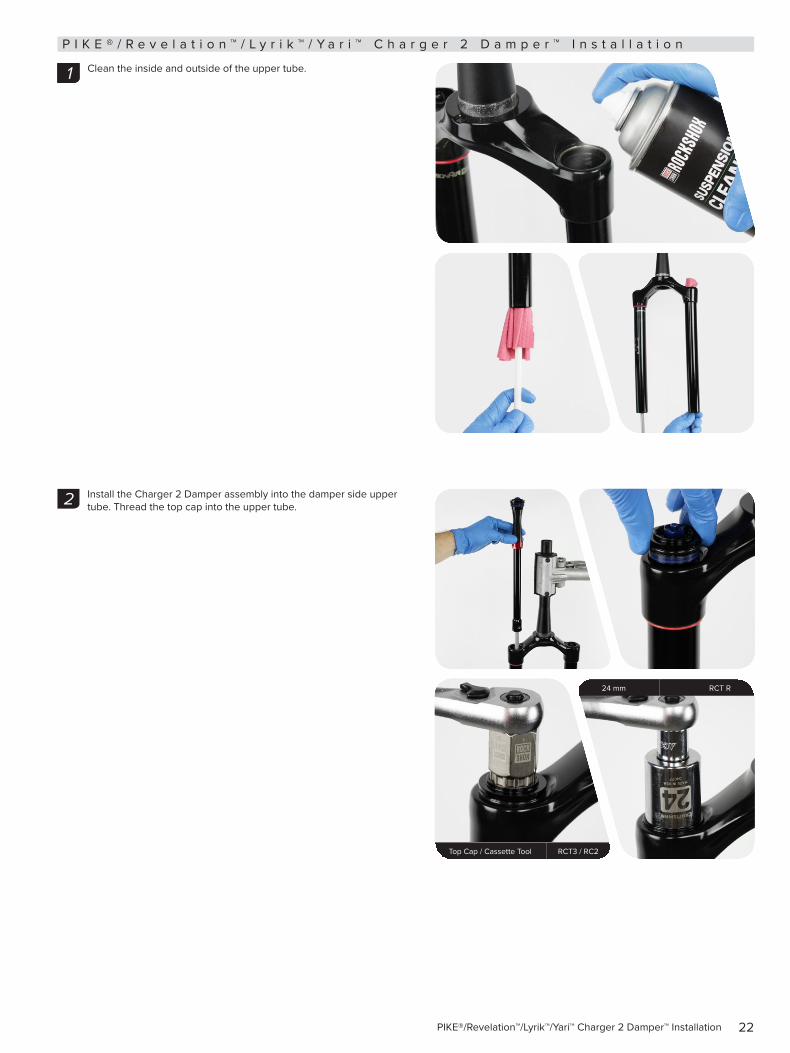
Clean the inside and outside of the upper tube.
Install the Charger 2 Damper assembly into the damper side upper tube. Thread the top cap into the upper tube.
1 1 1
2
Top Cap / Cassette Tool RCT3 / RC2
24 mm RCT R
23PIKE®/Revelation™/Lyrik™/Yari™ Charger 2 Damper™ Installation
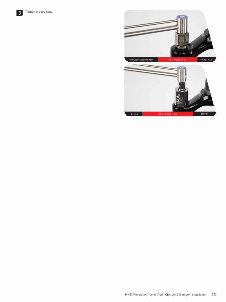
Tighten the top cap.3
Top Cap / Cassette Tool 28 N·m (250 in-lb) RCT3/ RC2
24 mm 28 N·m (250 in-lb) RCT R

24PIKE®/Revelation™/Lyrik™/Yari™ Charger 2 Damper™ Installation
RCT3: Install the compression mode adjuster knob onto the top cap with the tab in the forward, unlocked position.
RC2: Install the high speed compression adjuster knob.
RC2/ RCT 3: Install the low speed compression adjuster knob onto the hex adjuster rod.
Install and tighten the retaining screw.
4
RCT3
RC2
RC2
2 mm 1.2 N·m (10 in-lb)
2 mm 1.2 N·m (10 in-lb)

25PIKE®/Revelation™/Lyrik™/Yari™ Charger 2 Damper™ Installation
RCT R: Install the cable stop collar with the housing guide in the 6 o'clock forward position, angled ≈20 degrees from center.
Install the remote spool onto the hex adjuster with the cable set screw oriented within the 87° range zone.
Install the glide ring and low speed adjuster knob onto the hex adjuster. Install and tighten the knob retaining screw.
Tighten the cable stop collar set screw.
Consult the RockShox® remote user manual at https://www.sram.com/rockshox/component/remotes for cable and remote installation instructions.
PIKE®/Revelation™/Lyrik™/Yari™ Continue with Lower Leg Installation.
5
RCT R
2 mm 1.2 N·m (10 in-lb)
2 mm 0.25 - 0.6 N·m (2.2 - 5.3 in-lb)
87°
20°

26BoXXer® Charger Damper™ RC2 Installation
B o X X e r ® C h a r g e r D a m p e r ™ R C 2 I n s t a l l a t i o n
Push the rebound damper shaft in to leave room to inject oil into the lower leg. Install the Charger 2 Damper™ assembly into the damper side upper tube. Thread the top cap into the upper tube.
NOTICETo prevent scratching the rebound damper shaft, use your fingers to protect and guide the shaft as you install or remove the Charger 2 Damper from the upper tube.
Tighten the top cap.
1
Top Cap / Cassette Tool
2
Top Cap / Cassette Tool 7.3 N·m (65 in-lb)

27BoXXer® Charger Damper™ RC2 Installation
Install the high speed compression adjuster knob.
Install the low speed compression adjuster knob onto the hex adjuster rod.
Install and tighten the retaining screw.
BoXXer® Continue with Lower Leg Installation, step 4.
3
2 mm 1.2 N·m (10 in-lb)

28Lower Leg Installation
L o w e r L e g I n s t a l l a t i o nThe procedure for installing the lower leg is similar across RockShox® front suspension forks. Your fork's knobs, bolts, and chassis may appear different from the pictures. Consult your fork's service manual for more detailed instructions.
Clean the upper tubes.
BoXXer®: Continue to step 4 if the lower legs are installed.
Apply grease the inner surfaces of the wiper seals.
Slide the lower leg onto the upper tube enough to engage the upper bushing with the upper tube.
NOTICEMake sure both wiper seals slide onto the tubes without folding the outer lip of either seal.
The inside bottom of the lower leg should not contact the spring or damper shafts. A gap between the shaft ends and the lower leg bolt holes should be visible.
1
SRAM® Butter
2
3

29Lower Leg Installation
Position the fork at an angle with the lower leg bolt holes oriented upward.
Angle a syringe fitting in each lower leg bolt hole so the fluid will only contact the inside of the lower leg.
Consult the Front Suspension Oil, Air, Coil Spring Specification Chart at www.sram.com/service for your fork's recommended oil weight and volume.
Inject the suspension oil into each lower leg through the lower leg bolt hole.
NOTICEDo not exceed the recommended oil volume per leg as this can damage the fork.
Slide the lower leg assembly toward the crown until it stops.
Verify each shaft is centered and seated in the lower leg shaft/bolt hole and no gap is visible between the lower leg and the shaft end.
Install the black bottom bolt into the spring side shaft of the lower leg. Install the hollow bottom bolt into the damper side shaft of the lower leg.
Oil wt and Volume vary
4
5
5 mm 32 mm: 6.8 N·m (60 in-lb) 35 mm: 7.3 N·m (65 in-lb)
5 mm 32 mm: 6.8 N·m (60 in-lb) 35 mm: 7.3 N·m (65 in-lb)
6

30Lower Leg Installation
Install the rebound damper knob.
Tighten the set screw, if present.
Do not over-tighten the set screw. Over-tightening will seize the adjuster knob and it will not turn.
Clean the entire fork.
This concludes the upgrade to Charger 2 Damper™.
7
2.5 mm 0.85 N·m (7.5 in-lb)
8

www.sram.com
ASIAN HEADQUARTERS SRAM Taiwan No. 1598-8 Chung Shan Road Shen Kang Hsiang, Taichung City Taiwan R.O.C.
WORLD HEADQUARTERS SRAM LLC
1000 W. Fulton Market, 4th Floor Chicago, Illinois 60607
USA
EUROPEAN HEADQUARTERS SRAM Europe
Paasbosweg 14-16 3862ZS Nijkerk
The Netherlands