Characterizing Engineering Properties of Foundry Sands
44
Characterizing Engineering Properties of Foundry Sands Craig H. Benson, PhD, PE Recycled Materials Resource Center University of Washington [email protected] www.recycledmaterials.org © Recycled Materials Resource Center 20087
Transcript of Characterizing Engineering Properties of Foundry Sands

Characterizing Engineering
Properties of Foundry Sands
Craig H. Benson, PhD, PE
Recycled Materials Resource Center
University of Washington [email protected]
www.recycledmaterials.org
© Recycled Materials Resource Center 20087

Participant Background
© Recycled Materials Resource Center 20087
Which of the following describes your training:
• Civil Engineer or Environmental Engineer.
• Geologist
• Environmental scientist
• Other

Participant Background
© Recycled Materials Resource Center 20087
Which describes your employment:
• Private sector
• Public sector
• Designer
• Regulator
• Construction
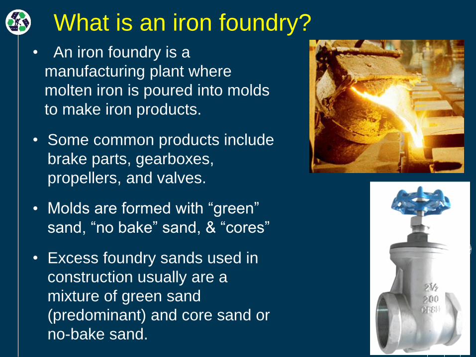
What is an iron foundry? • An iron foundry is a
manufacturing plant where
molten iron is poured into molds
to make iron products.
• Some common products include
brake parts, gearboxes,
propellers, and valves.
• Molds are formed with “green”
sand, “no bake” sand, & “cores”
• Excess foundry sands used in
construction usually are a
mixture of green sand
(predominant) and core sand or
no-bake sand.


What is foundry sand?
Foundry sands are sand-bentonite mixtures.
Base Sand
85%
Organic 3%
Water 5%Bentonite 7%

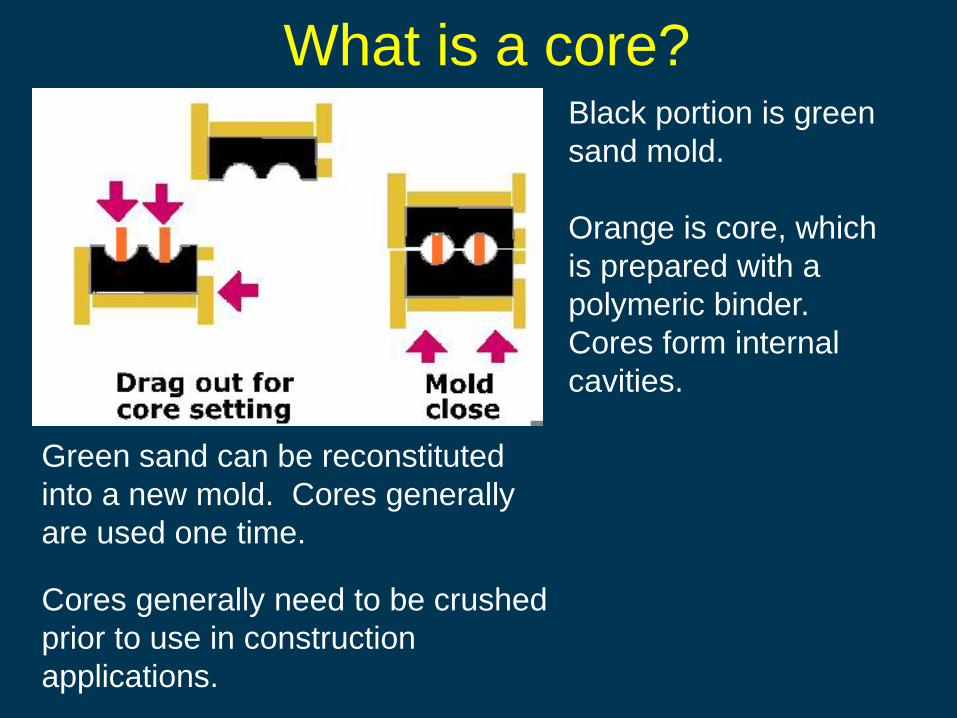
What is a core? Black portion is green
sand mold.
Orange is core, which
is prepared with a
polymeric binder.
Cores form internal
cavities.
Green sand can be reconstituted
into a new mold. Cores generally
are used one time.
Cores generally need to be crushed
prior to use in construction
applications.

Why is foundry sand discarded?
• High temperature and pressure degrade the sand
over time.
• Sand becomes contaminated with debris (flashing,
dust, core pieces etc).
• New ingredients (sand, bentonite, are added to
ensure sand has suitable properties.
• Addition of new ingredients results in too much
sand in the system, or “excess” sand. Thus, some
of the sand is removed and discarded.
• Discarded sand is sometimes referred to as
“excess system sand,” or ESS.
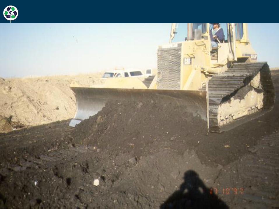

Foundry sand
grades and
shapes easily.
Compacts well
with modest
amount of
moisture.

Foundry sand
being spread as
sub-base at STH
60 field site.
Foundry slag being
compacted at STH 60

Recap • What are the basic types of iron foundry
sands that might be encountered in a reuse
application: (a) green sand, (b) core sand,
(c) no-bake sand, or (d) all of the above?
• True or false: bentonite is added to sand to
make “green” sand cohesive.
• True or false: Sand is bonded using
polymeric adhesives to create cores.
• Foundry sand is discarded because (a) the
sand has the incorrect color, (b) excess sand
accumulates at the foundry, or (c) the sand
contains gravel?
Infrastructure Applications
• Subbase and working platforms for
roadways and paved areas
• Retaining wall backfill, embankment fill, and
structural fill
• HMA and CLSM fine aggregate
• Pond liner (e.g., runoff)

Participant Experience
© Recycled Materials Resource Center 20087
Check if you have designed or constructed the following:
• Roadway
• Structural fill
• Retaining wall
• Embankment

Participant Experience
© Recycled Materials Resource Center 20087
Check if you have used foundry sand in the following:
• Roadway construction
• Structural fill
• Retaining walls
• Embankments
• Top soil applications

Subbase Applications
• California
bearing ratio
(CBR)
• Resilient
modulus
Objective: provide
designers with typical
engineering properties
for foundry sands that
can be used in
preliminary design.

Conventional
Wall MSE Wall
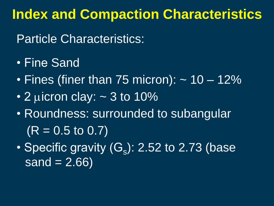
Index and Compaction Characteristics
Particle Characteristics:
• Fine Sand
• Fines (finer than 75 micron): ~ 10 – 12%
• 2 micron clay: ~ 3 to 10%
• Roundness: surrounded to subangular
(R = 0.5 to 0.7)
• Specific gravity (Gs): 2.52 to 2.73 (base
sand = 2.66)

0
20
40
60
80
100
0.010.1110
Pe
rce
nt
Fin
er
(%)
Particle Diameter (mm)
14 Foundry Sands from
WI, IL, MI, & IN
1. Uniform
2. Do not differ
appreciably
between
sources
Base Sand
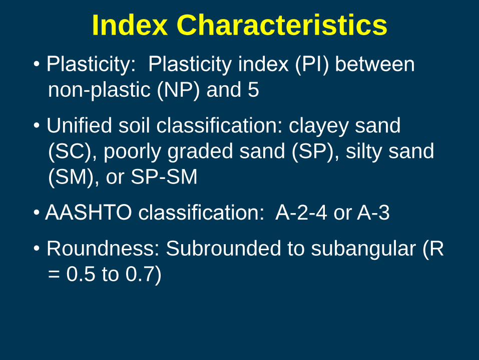
Index Characteristics
• Plasticity: Plasticity index (PI) between
non-plastic (NP) and 5
• Unified soil classification: clayey sand
(SC), poorly graded sand (SP), silty sand
(SM), or SP-SM
• AASHTO classification: A-2-4 or A-3
• Roundness: Subrounded to subangular (R
= 0.5 to 0.7)
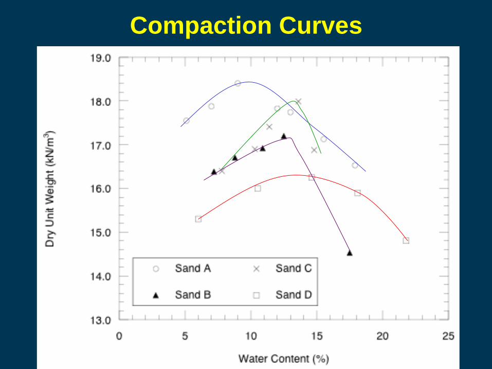
Compaction Curves

Recap – Applications & Characteristics
• Foundry sands can be used in lieu of virgin
materials in the following applications: (a)
roadway subbase, (b) retaining wall backfill,
(c) flowable fill (CLSM), or (d) all of the above.
• What is the primary characteristic that varies
between foundry sands: (a) sand roundness,
(b) fines and clay content, or (c) color?
• True or False: compaction curves for foundry
sands appear very different than those for
soils.

Engineering Properties of Interest
• Geotechnical properties
- strength (retaining structure backfill,
embankment)
- compressibility & stiffness (embankment,
subbase)
- interaction with geosynthetic materials
- hydraulic conductivity (water retention liner)
• Interactions with binders (HMA, CSLM)

Pavement Applications - Subbase
• California bearing ratio (CBR) – measure of
bearing strength of unbound pavement
materials (subgrade, subbase, or base).
• Resilient modulus – stiffness of unbound or
bound pavement material that accounts for
effect of long-term cyclic pavement loads
Modern mechanistic pavement design
employs resilient modulus. However, CBR is
still used in lower volume roadway designs.

CBR Test

Resilient Modulus Test

ESS #Penetration
Curve TypeP200 PI Max CBR
1 Brittle 10.7 NP 40
2 Ductile 12.7 3 8.7
3 Brittle 4.3 NP 10
4 Brittle 1.1 NP 18
5 Ductile 14.3 1 19
6 Ductile 11.3 2 22
7 Brittle 2.7 NP 10
8 Ductile 12.1 8 27
9 Ductile 13.2 4 28
10 Ductile 12.4 5 4.3
11 Ductile 10.2 3 8.1
12 Ductile 16.4 6 16
13 Ductile 13.2 3 32
14 Brittle 10.0 NP 33
Reference Base 80
Reference Subbase 17
CBR of Foundry Sands • Higher CBR
obtained with a
greater fraction
of non-plastic
fines.
• Plastic fines
reduce CBR
• Higher CBR at
optimum water
content and with
greater density.

Non-Plastic (NP) Sands:
gd is dry density in kN/m3, P200 is fines
content in %, R is Krumbein roundness,
BC = bentonite content (%)
CBR = -361 + 32.4gd - 1.93P200 -
264R Plastic Sands (PI > 0):
CBR = -7.6gd + 4.25 BC + 178R
Estimating CBR of Foundry Sands

0 100
100 103
200 103
300 103
400 103
0 200 400 600 800
ESS 1
ESS 4
ESS 5
ESS 7
ESS 14
Base
Reference
Subbase
ReferenceM
r (k
Pa)
sb (kPa)
Resilient
Modulus:
BC < 6%
• Many foundry
sands have
modulus falling
between
conventional
subbase and
base.
0 100
100 103
200 103
300 103
400 103
0 200 400 600 800
ESS 2
ESS 6
ESS 8
ESS 9
ESS 10
ESS 11
ESS 12
ESS 13
Base
ReferenceSubbase
Reference
Mr (k
Pa
)
sb (kPa)
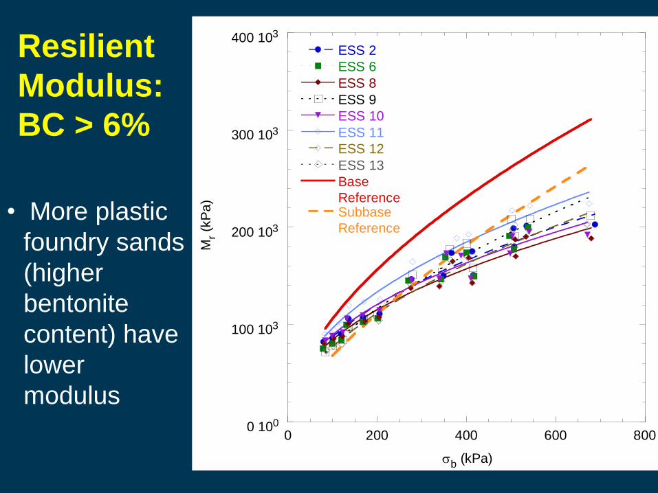
Resilient
Modulus:
BC > 6%
• More plastic
foundry sands
(higher
bentonite
content) have
lower
modulus
0 100
100 103
200 103
300 103
400 103
0 200 400 600 800
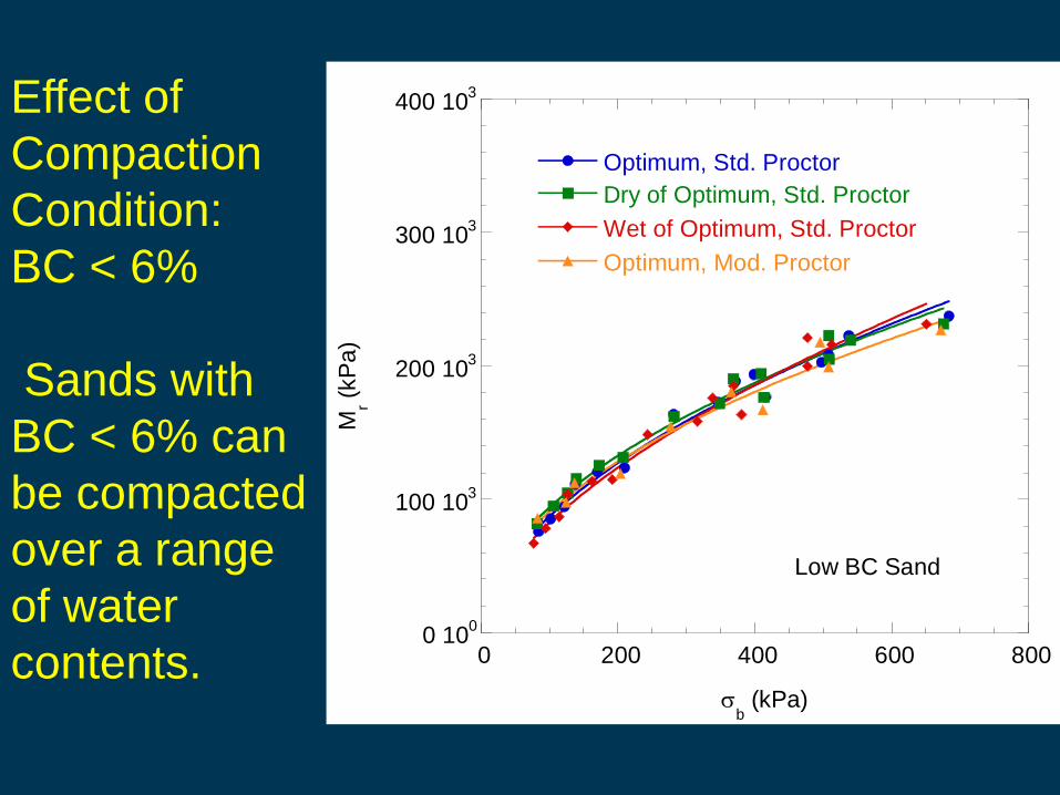
Optimum, Std. Proctor
Dry of Optimum, Std. Proctor
Wet of Optimum, Std. Proctor
Optimum, Mod. Proctor
Mr (
kP
a)
sb (kPa)
Low BC Sand
Effect of
Compaction
Condition:
BC < 6%
Sands with
BC < 6% can
be compacted
over a range
of water
contents.

0 100
100 103
200 103
300 103
400 103
0 200 400 600 800
Optimum, Std. Proctor
Dry of Optimum, Std. Proctor
Wet of Optimum, Std. Proctor
Optimum, Mod. Proctor
Mr (
kP
a)
sb (kPa)
High BC
Sand
Effect of
Compaction
Condition:
BC > 6%
Plastic sands
should be
compacted
near optimum
water content.
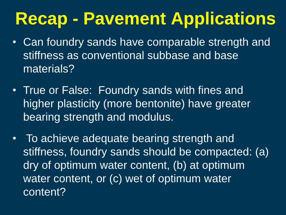
Recap - Pavement Applications
• Can foundry sands have comparable strength and
stiffness as conventional subbase and base
materials?
• True or False: Foundry sands with fines and
higher plasticity (more bentonite) have greater
bearing strength and modulus.
• To achieve adequate bearing strength and
stiffness, foundry sands should be compacted: (a)
dry of optimum water content, (b) at optimum
water content, or (c) wet of optimum water
content?

Retaining Structure Backfill,
Structural Fill, Embankment Fill
• Shear strength of foundry sands
• Interface shear strengths with
geomembrane, woven geotextile, and
geogrid
• Pullout with geotextile and geogrid
0
20
40
60
80
100
0 10 20 30 40 50 60
Sh
ear
Str
ess (
kP
a)
Normal Stress (kPa)
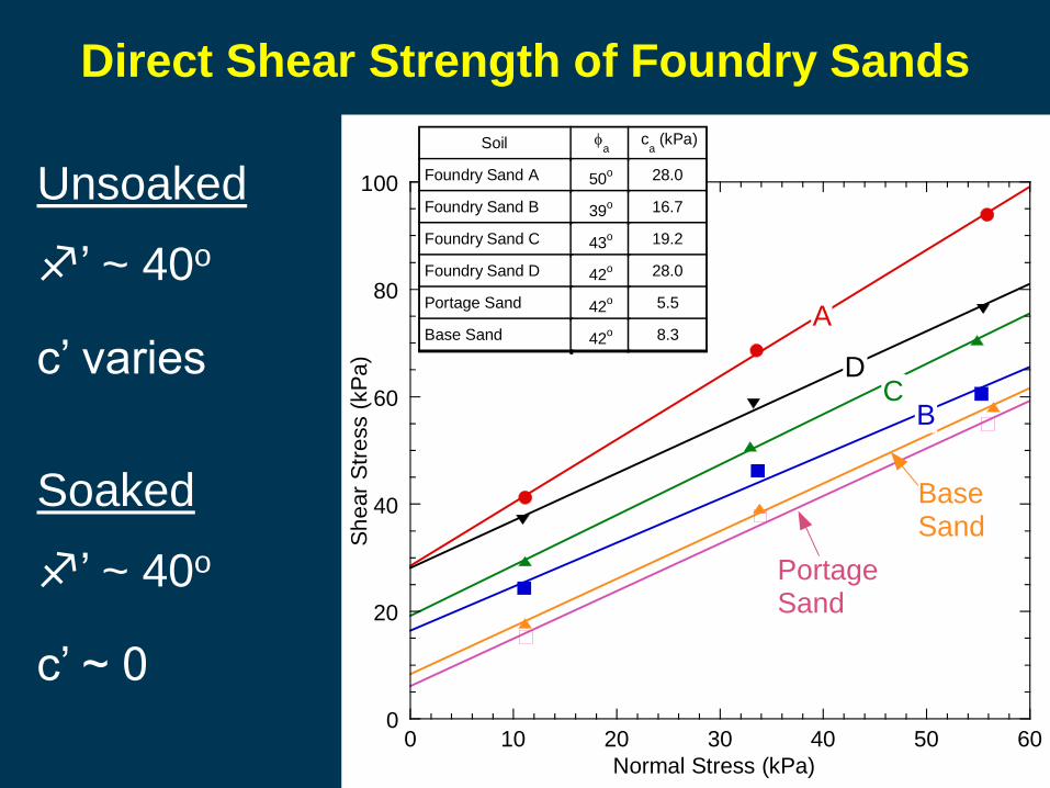
ca (kPa)f
aSoil
28.050oFoundry Sand A
16.739oFoundry Sand B
19.243oFoundry Sand C
28.042oFoundry Sand D
5.542oPortage Sand
8.342oBase Sand
A
DC
B
BaseSand
PortageSand
Direct Shear Strength of Foundry Sands
Soaked
f’ ~ 40o
c’ ~ 0
Unsoaked
f’ ~ 40o
c’ varies
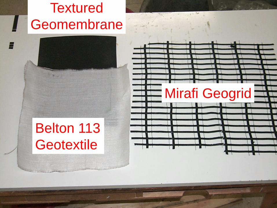
Mirafi Geogrid
Belton 113
Geotextile
Textured
Geomembrane

LVDT
Load Cells
Porous Stone Substrate
Soil
Pressurized
Air Bladder
LVDT
Geosynthetic
Direction of
Displacement
Track
Lower
Shear Box
Clamp Geosynthetic
Clamp
Large-Scale (D 5321) Direct Shear Machine

Interface Direct Shear Box (300 mm x 300 mm)
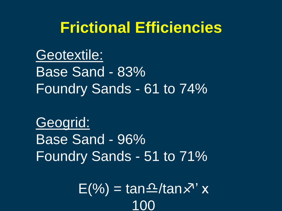
Frictional Efficiencies
E(%) = tand/tanf’ x
100
Geotextile:
Base Sand - 83%
Foundry Sands - 61 to 74%
Geogrid:
Base Sand - 96%
Foundry Sands - 51 to 71%

Retaining Wall and Structural
Fill Design Recommendations
• f’ = 40o, c’ = 0
• E = 55% (geogrid) or 65% (geotextile)
• Ci = 1 (low normal stresses)
• Ci = 0.5 (higher stresses)
• Compact near optimum water content.

Recap – Fill Applications
• True or False: the shear strength of foundry sands
varies significantly between foundries.
• Frictional efficiencies between geosynthetics and
foundry sands range between (a) 25-50%, (b) 50-
75%, or (c) 75-100%.
• Foundry sands used for fill should be compacted
(a) as dry as possible, (b) near optimum water
content, or (c) 3% wet of optimum.

Hydraulic Conductivity
10-9
10-8
10-7
10-6
10-5
10-4
10-3
10-2
10-1
0 5 10 15 20
Laboratory Data
Mean of Field Ks
SDRI
Hyd
rau
lic C
on
du
ctivity (
cm
/se
c)
Bentonite Content - By Weight (%)
13
2

Hydraulic Conductivity
• Foundry sands will drain less effectively than
conventional sands.
• Foundry sands with bentonite content < 6%
preferred for better drainage.