Characterization of Elastomeric Diaphragm Motion · PDF fileCharacterization of Elastomeric...
20
1 Characterization of Elastomeric Diaphragm Motion within a Spacecraft Tank During Ground Transportation Gabriel Lapilli 1 , Brian Wise 2 , Hector Gutierrez 3 , and Daniel Kirk 4 Florida Institute of Technology, Melbourne, Florida 32901 Walter Tam 5 and Manoj Bhatia 6 ATK Space Systems Inc., Commerce, California 90040 Diaphragm tanks are used in a variety of launch vehicle and spacecraft applications. Characterization of diaphragm behavior is important for mission assuredness. Knowing the shape and behavior of the diaphragm is also important during ground transportation and while the vehicle is on the launch pad. During transportation, the tank is filled with propellant and the tank may be oriented either vertically or horizontally which applies loads to the diaphragm. If forces are large enough, diaphragm pull-out may occur. In this study a 40 inch tank with an elastomeric diaphragm was transported in various orientations and fill fractions. During these tests the acceleration profile of the transport vehicle was measured and correlated with stereo images of the diaphragm. This work characterizes the diaphragm shape and motions during transportation in vertical, horizontal and inverted horizontal tank orientations for fill fractions of 25% - 85%. In the horizontal case, for fill fractions 34% – 66%, diaphragm rubber-to-rubber and rubber-to-tank wall rubbing occurred. For all other fill fractions and tank orientations the diaphragm did not rub. Excitation frequencies between 0.55 and 0.85 Hz were observed to cause sloshing motion of the fluid/diaphragm system. For the inverted horizontal case, the fluid can flip its stable state to the opposite horizontal quadrant of the tank. Nomenclature FF = Fill Fraction, liquid to tank volume ratio 1 Graduate Student, Mechanical and Aerospace Engineering, 150 W. University Blvd. 2 Graduate Student, Mechanical and Aerospace Engineering, 150 W. University Blvd. Student Member AIAA. 3 Associate Professor, Mechanical and Aerospace Engineering, 150 W. University Blvd. 4 Associate Professor, Mechanical and Aerospace Engineering, 150 W. University Blvd. Associate Fellow AIAA. 5 Director, Business Development, ATK Space Systems Inc., 6033 East Bandini Blvd, Commerce, CA 90040. 6 Program Manager, ATK Space Systems Inc., 6033 East Bandini Blvd, Commerce, CA 90040.
Transcript of Characterization of Elastomeric Diaphragm Motion · PDF fileCharacterization of Elastomeric...

1
Characterization of Elastomeric Diaphragm Motion within a
Spacecraft Tank During Ground Transportation
Gabriel Lapilli1, Brian Wise
2, Hector Gutierrez
3, and Daniel Kirk
4
Florida Institute of Technology, Melbourne, Florida 32901
Walter Tam5 and Manoj Bhatia
6
ATK Space Systems Inc., Commerce, California 90040
Diaphragm tanks are used in a variety of launch vehicle and spacecraft applications.
Characterization of diaphragm behavior is important for mission assuredness. Knowing the
shape and behavior of the diaphragm is also important during ground transportation and
while the vehicle is on the launch pad. During transportation, the tank is filled with
propellant and the tank may be oriented either vertically or horizontally which applies loads
to the diaphragm. If forces are large enough, diaphragm pull-out may occur. In this study a
40 inch tank with an elastomeric diaphragm was transported in various orientations and fill
fractions. During these tests the acceleration profile of the transport vehicle was measured
and correlated with stereo images of the diaphragm. This work characterizes the diaphragm
shape and motions during transportation in vertical, horizontal and inverted horizontal tank
orientations for fill fractions of 25% - 85%. In the horizontal case, for fill fractions 34% –
66%, diaphragm rubber-to-rubber and rubber-to-tank wall rubbing occurred. For all other
fill fractions and tank orientations the diaphragm did not rub. Excitation frequencies
between 0.55 and 0.85 Hz were observed to cause sloshing motion of the fluid/diaphragm
system. For the inverted horizontal case, the fluid can flip its stable state to the opposite
horizontal quadrant of the tank.
Nomenclature
FF = Fill Fraction, liquid to tank volume ratio
1 Graduate Student, Mechanical and Aerospace Engineering, 150 W. University Blvd.
2 Graduate Student, Mechanical and Aerospace Engineering, 150 W. University Blvd. Student Member AIAA.
3 Associate Professor, Mechanical and Aerospace Engineering, 150 W. University Blvd.
4 Associate Professor, Mechanical and Aerospace Engineering, 150 W. University Blvd. Associate Fellow AIAA.
5 Director, Business Development, ATK Space Systems Inc., 6033 East Bandini Blvd, Commerce, CA 90040.
6 Program Manager, ATK Space Systems Inc., 6033 East Bandini Blvd, Commerce, CA 90040.

2
g = Gravitational acceleration, 9.81 m/s2
h = Liquid fill height within the tank, m
MA = Maximum Acceleration in direction of travel, g’s
R0 = Major tank radius, m
Rvert = Minor tank radius, m
TO = Tank Orientation, degrees
n = Sloshing frequency, Hz
I. Introduction
LASTOMERIC diaphragm tanks have been in use since the early stages of space flight as an effective means
for propellant management [1] – [4]. Elastomeric diaphragm tanks utilize positive expulsion technology for liquid
propellant control and delivery. The term positive expulsion describes the use of a pressure differential to expel
propellant from its storage vessel. Positive expulsion devices include diaphragms, bladders, pistons or bellows-based
systems for fluid control and delivery. Two of the most practical types of spacecraft propulsion fluid control devices
have proven to be diaphragms and bladders, which use elastomeric materials for an effective barrier between the
pressurant gas and the liquid propellant. The majority of such tanks are used in monopropellant hydrazine systems,
and most diaphragms are made using ATK’s (formerly Pressure Systems, Inc.’s (PSI)) unique elastomeric reversing
ethylene-propylene terpolymer (AF-E-332) material. Mounting is accomplished on a continuous flange parallel with
and adjacent to the mid-plane. A typical elastomeric diaphragm tank assembly is shown in Fig.1.
Fig.1 A typical elastomeric diaphragm tank assembly [3]
E

3
Diaphragm tanks are positive expulsion devices with an internal membrane to separate the propellant compartment
from the pressurant compartment. Fig.1 illustrates the typical embodiment of a diaphragm tank. In most cases the
diaphragms are hemispherical or hemispherical with an integral cylindrical section and the outermost edge of the
open-end of the diaphragm is sealed against the pressure shell. In the ATK diaphragm design the sealing bead is
retained by a metallic retaining ring which is welded to the tank shell during the weld closure of the exterior
pressure shell. Alternative designs achieve diaphragm retention by a clamping device that is mechanically fastened
to an intermediate cylinder or by a mechanically trapping the diaphragm directly between the upper and lower
pressure shells. Diaphragm tanks are typically easier to manufacture and have less severe folding patterns during
operation than bladder tanks, whereas bladder tanks have a smaller sealing area and are easier to install, remove and
replace as compared with diaphragm tanks [1].
The spacecraft propellant tank(s) are filled prior to transportation to the launch pad and prior to stacking onto the
launch vehicle. The spacecraft or upper-stage may be transported to the assembly/integration hanger or launch pad
in the horizontal configuration and then rotated 90 degrees for stacking onto the booster stage. Depending on the
mission propellant requirements, typical fill fractions range from 75% to 95%, and while the spacecraft is in the
horizontal position for transportation, the fluid mass can provide significant pull-out forces on where the diaphragm
is held by the clamping ring. The accelerations of the transportation vehicle, while small, can exert additional forces
on the liquid and can even establish a resonance with some of the lower fluid slosh modes, thus leading to even
larger induced forces. Furthermore, if the diaphragm has several folds in it that are in contact with each other,
rubbing may occur during transportation that can weaken and fatigue the diaphragm material prior to flight. A
rupture or tear in the diaphragm material would lead to complete loss of mission.
Diaphragm rubbing is of particular concern in larger diameter tanks. For the ATK series of tanks, the elastomeric
diaphragm material has the same thickness (0.07 inch) for all tanks with 9.4 to 40 inch diameter. This suggests that
the stiffness of the diaphragm is higher for the smaller diameter tanks and more flexible for the larger diameters.
Furthermore, the fluid mass inside the tank scales with the radius cubed (for a spherical tank) and the diaphragm
area scales with the radius squared; this means that for two tanks with the same fill reaction, a tank that is twice as
large in diameter has 8 times the propellant mass and twice the force per unit diaphragm area.
In addition to ground transportation, similar concerns exist for having a more thorough knowledge of the
diaphragms behavior once the vehicle is stacked and sitting on the launch pad. For example, wind sway concerns for

4
long, slender rockets are an important consideration. The spacecraft tank, which is located near the top of the
vehicle, can experience a sinusoidal oscillation associated with the interaction of the wind with the launch vehicle.
Oscillations frequencies in the 0 to 3 Hz range with several inches of lateral displacement are common testing
ranges. Similar concerns exist for developing an improved understanding of diaphragm rub during launch pad sway.
In order to achieve a better understanding of how tank transportation can lead to diaphragm rub or excite natural
slosh frequencies, a series of studies were performed using the 40 inch acrylic tank shown in Fig.2 and Fig.3.
Specifically, the objectives of this study are to:
1) Perform a range of tests that include transportation acceleration levels, tank fill levels, and tank orientations
to determine if there is large-scale motion of the diaphragm during transportation.
2) Determine which transportation acceleration levels, tank fill levels, and tank orientations resulted in the
largest displacement of the diaphragm.
3) Identify from the obtained images the correlation between transportation acceleration level, tank fill level,
tank orientation and the resulting liquid sloshing frequency.
4) Determine the range of tank fill levels, associated with a specific tank orientation, during which diaphragm
rubbing and folding was observed during transportation.
5) Develop an experimental framework that can be used for future elastomeric diaphragm tank behavior
studies for transportation and on-pad behavior.
Section II presents a literature review and brief historical account of positive expulsion technology elastomeric
diaphragm tanks and a description of the 40 inch ATK tank used in this study. Section III provides a description of
the experimental set-up used to simulate ground transportation, in various orientations and fill levels, of the 40 inch
tank. Section IV presents the results and the findings of this study, and Section V presents a summary and
conclusions.
II. Tank Description and Tank Slosh Overview
The 40 inch diaphragm tank is one of the larger tanks in the ATK diaphragm tank product line. The 40-inch
oblate spheroid pressure vessel is constructed of 6Al-4V titanium, and the tank has a total volume of 28,144 in3.
This tank has long history of service, starting with the Tracking and Data Relay Satellite (TDRS). ATK shipped the

5
first TDRS tank in the late 1970’s. Many details associated with the history of elastomeric diaphragm design,
fabrication and test, as well as a summary of the many tank sizes, ranging from 9.4 to 40 inches in diameter, and
programs on which elastomeric tanks have been successfully used can be found in reference [4].
In order to study the behavior of the elastomeric diaphragm in various transportation loading scenarios, a 40 inch
diameter acrylic simulator tank is used. The tank has a major radius R0 of 20 inches and a minor radius Rvert of 14,
thus giving a ratio of Rvert/R0=0.707. The acrylic simulator tank was originally built to test the TDRSS diaphragm
tank, P/N 80263, [5]. A schematic of the tank and a picture of the acrylic tank are shown in Fig.2.
Fig.2 (left) schematic of the P/N 80263 TDRSS hydrazine tank, and (right) picture of the 40 inch acrylic
simulator tank
NASA Goddard took possession of the tank after the program, and a Space Act Agreement was signed in 2010 to
have the tank stored at the ATK Commerce, CA facility. The empty tank was shipped to the Florida Institute of
Technology’s Aerospace Systems And Propulsion (ASAP) Laboratory for the ground transportation simulation tests.

6
The elastomeric diaphragm material has a thickness of 0.07 inch. The diaphragm has ridges located on the
propellant side to minimize propellant residual and the tanks are designed to produce greater than 99.9% propellant
expulsion. Without these ribs, pockets might form to prevent propellant from reaching the outlet port.
Examples of different fluid fill fractions in a 40 inch diameter tank with acrylic hemispheres for visualization
studies are shown in Fig.3. In these examples, the propellant side is down and the pressurant side is up.
Fig.3 Examples of elastomeric diaphragm in a 40 inch diameter tank, (a) 50% fill fraction, (b) 75% fill
fraction, (c) and (d) show examples of diaphragm folding. Images courtesy of NASA.
As can be seen in Fig.3, the diaphragm naturally folds onto itself at most intermediate fill levels, other than
completely full and nearly empty cases. In the intermediate range, the diaphragm makes contact with itself or even
with the edges of the tank wall.
One of the objectives of this study is to understand and quantify the interaction between the diaphragm and the
fluid motion within the tank as a result of excitations that occur during transportation or while the vehicle is on the
launch pad. Prior to examining the behavior of the coupled diaphragm/fluid system it is useful to baseline the natural

7
sloshing frequencies for a tank that contains no diaphragm. These natural sloshing frequencies can then be compared
with the measured frequencies of the excited coupled diaphragm/fluid system to determine if the diaphragm acts as a
damper or acts to further excite the system. Different diaphragm thicknesses can also be examined to determine the
effect of diaphragm stiffness on the resulting system sloshing frequencies.
For smooth internal wall tanks, without a diaphragm, the slosh frequencies are well known as a function of the
tank geometry and fill fraction, [6]. Fig.4 provides an example of a plot showing the natural frequency parameter
versus the liquid depth ratio, h/Rvert, for an oblate spheroid tank. The plot shows the first and second slosh modes for
a range of Rvert/R0 between 0.5 and 2.0 with 1.0 corresponding to the spherical tank case.
Fig.4 Theoretical sloshing frequencies for an oblate spheroid tank, [6]
Fig.4 can be used to estimate the first and second slosh frequencies for the tank under study in the transportation
experiments as a function of the fill fraction and tank orientation. For a fill fraction of 50, corresponding to h/Rvert=1,
and with Rvert/R0=0.707, the theoretical natural frequency parameter is about 1.2. Using R0=0.508 m (20 inches) and

8
g=9.8 m/s2, this corresponds to the first mode sloshing frequency of n=0.84 Hz. More details on liquid sloshing
within moving containers can be found in References [7] – [9].
III. Experimental Set-up
The 40 inch diameter tank used for testing was mounted on a steel test rig with full 360 degree rotation
capability, mechanically lockable every 10 degrees with manual action. This test rig was rigidly attached with bolts
and straps to the load compartment of a commercial moving truck, as shown in Fig.5. The photo shown in Fig.5 is
shown from the direction toward the front of the truck, i.e. in the direction of forward truck travel.
Fig.5 Test rig mounted on the vehicle, seen from the back of the truck, TO = 0 degrees
Appropriate piping and auxiliary systems were connected to the propellant hemisphere of the tank in order to fill and
empty the tank with water (hydrazine has a specific gravity of 1.008 at 20 °C). The water weight was measured, and
along with compensation for temperature, the volume of water within the tank was estimated to establish the tank fill
fraction, FF. A pressure control system was installed to the pressurant hemisphere (using compressed air) and during

9
several of the tests a positive pressure was applied in an attempt to determine if the positive pressure in any way
altered the diaphragm dynamics during a test.
Lighting was installed on the propellant side of the tank, while two cameras were installed looking at the
pressurant hemisphere, each offset 45° from the travel direction (axis) of the truck. Regardless of the tank
orientation angle, the lighting and the camera orientation do not change with respect to the tank. The cameras are
labeled in accordance with a viewer on the camera-side (pressurant dome) of the tank, or in the configuration shown
in Fig.5 looking towards the back of the truck, or in the opposite direction of forward truck travel. The right and left
cameras both point toward the center of the tank and are 90° part. These two cameras are identical IDS model
5580CP with a resolution of 2560 x 1920 pixels and a 24 bit per pixel color depth. The lens attached to the camera is
a Thor Labs MVL4WA, with a focal length of 3.5 mm and an aperture of f/1.4. The image sampling rate was set to 5
Hz, with simultaneous triggering. The cameras used Ethernet connectivity and were powered using Power-Over-
Ethernet. A detail of one of the cameras is shown as an inset in Fig.5.
Two Inertial Measurement Units (IMU) consisting of a 3-axes accelerometer, a 3-axes gyroscope and a
magnetometer were also used. The IMU is a CH Robotics UM6. The first one was placed in a tank-reference frame
(which rotates with the tank as the tank orientation, TO, is varied), while the second one was placed on a truck-
reference frame (this IMU does not rotate with the tank and is used for data redundancy and to ensure that the
accelerations seen by the rig where exactly those experienced by the truck and that no damping was taking place).
The IMUs were sampled at a frequency of approximately 50 Hz, roughly 10 times higher than the camera. A detail
of one of the IMUs is shown as an inset in Fig.5. These data were low-pass filtered to 5Hz.
All the data collection system was run from a single laptop inside the truck cabin. The data collection software
running under Windows was custom-made for this application, able to parse and store the data from both IMUs and
both cameras simultaneously. All the data was time stamped to at least the millisecond precision. Three sets of tank
orientations were investigated, as shown in Fig.6. Because of the accelerating and decelerating transportation motion
of the transport vehicle, the 90° TO and 270° TO are equivalent.

10
90° TO 0° TO 180° TO
Fig.6 Experimental setup orientation diagram
Since the IMUs are mounted to the support frame of the tank (see Fig.5) and since the support frame is rotated to
achieve different TO angles, the orientation of the IMU changes with the TO angle. In Fig.6, the y-axis of the IMU
is always out of the page, or pointing to the drivers left of the truck, regardless of the TO. In the 90° TO case, the
positive z-axis points in the direction of truck forward travel and the positive x-axis points downward; in the 0° TO
case, the positive x-axis points in the opposite direction of forward truck travel and the positive z-axis points
downward; in the 180° TO case, the positive x-axis points in the direction of truck forward travel and the positive z-
axis points upward. This choice is made so that the camera viewing angles and the IMU coordinate system are
always in the same orientation with respect to each other, regardless of TO. The redundant IMU located on the truck
bed also has the same orientation as the 0° TO case. When examining the results presented in Section IV, it is
important to note the coordinate system of the x-, y-, and z-axis accelerations. Fig.6 also shows the viewing angles
of the two cameras with respect to the tank frame and the IMU located in the tank frame. With respect to the
tank/IMU frame, the right camera points in the direction of the positive x-axis, negative y-axis and positive z-axis,
whereas the left camera points in the direction of the positive x-axis, positive y-axis and positive z-axis.
IV. Results and Observations
This section presents the results and observations. A summary of the tests conducted and observations is
presented in Table 1. The tank orientation, TO, is in accordance with Fig.6; the fill fraction, FF, which is based on a
percentage of the total volume of the tank (28,144 in3); the pressure, P, is the positive pressure introduced into the
pressurant hemisphere; the maximum acceleration, MA, of the transportation vehicle in the direction of travel
reported in g’s (when observing the data sets pay close attention to the coordinate system shown in Fig.6 – since the
tank frame is rotated the orientation of the accelerometer also changes); Fold indicated whether or not the diaphragm
11
is folded on itself; and Rub indicates whether or not the diaphragm was observed to rub on itself or against the tank
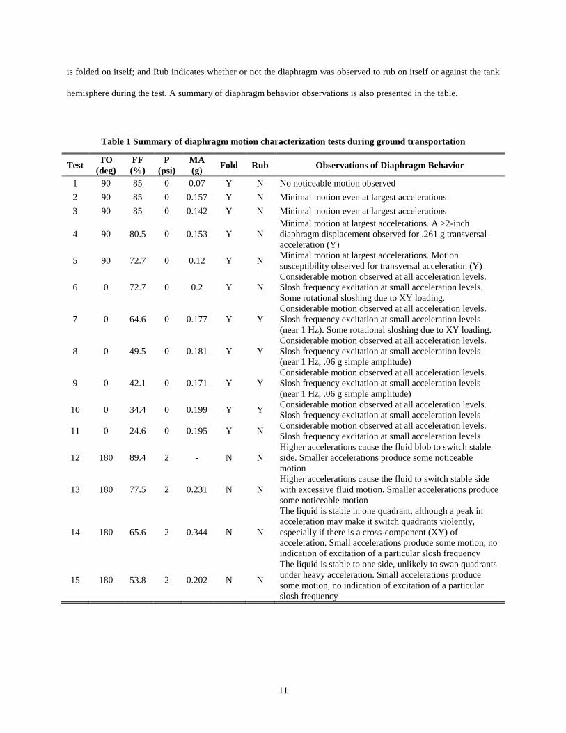
hemisphere during the test. A summary of diaphragm behavior observations is also presented in the table.
Table 1 Summary of diaphragm motion characterization tests during ground transportation
Test TO
(deg)
FF
(%)
P
(psi)
MA
(g) Fold Rub Observations of Diaphragm Behavior
1 90 85 0 0.07 Y N No noticeable motion observed
2 90 85 0 0.157 Y N Minimal motion even at largest accelerations
3 90 85 0 0.142 Y N Minimal motion even at largest accelerations
4 90 80.5 0 0.153 Y N
Minimal motion at largest accelerations. A >2-inch
diaphragm displacement observed for .261 g transversal
acceleration (Y)
5 90 72.7 0 0.12 Y N Minimal motion at largest accelerations. Motion
susceptibility observed for transversal acceleration (Y)
6 0 72.7 0 0.2 Y N
Considerable motion observed at all acceleration levels.
Slosh frequency excitation at small acceleration levels.
Some rotational sloshing due to XY loading.
7 0 64.6 0 0.177 Y Y
Considerable motion observed at all acceleration levels.
Slosh frequency excitation at small acceleration levels
(near 1 Hz). Some rotational sloshing due to XY loading.
8 0 49.5 0 0.181 Y Y
Considerable motion observed at all acceleration levels.
Slosh frequency excitation at small acceleration levels
(near 1 Hz, .06 g simple amplitude)
9 0 42.1 0 0.171 Y Y
Considerable motion observed at all acceleration levels.
Slosh frequency excitation at small acceleration levels
(near 1 Hz, .06 g simple amplitude)
10 0 34.4 0 0.199 Y Y Considerable motion observed at all acceleration levels.
Slosh frequency excitation at small acceleration levels
11 0 24.6 0 0.195 Y N Considerable motion observed at all acceleration levels.
Slosh frequency excitation at small acceleration levels
12 180 89.4 2 - N N
Higher accelerations cause the fluid blob to switch stable
side. Smaller accelerations produce some noticeable
motion
13 180 77.5 2 0.231 N N
Higher accelerations cause the fluid to switch stable side
with excessive fluid motion. Smaller accelerations produce
some noticeable motion
14 180 65.6 2 0.344 N N
The liquid is stable in one quadrant, although a peak in
acceleration may make it switch quadrants violently,
especially if there is a cross-component (XY) of
acceleration. Small accelerations produce some motion, no
indication of excitation of a particular slosh frequency
15 180 53.8 2 0.202 N N
The liquid is stable to one side, unlikely to swap quadrants
under heavy acceleration. Small accelerations produce
some motion, no indication of excitation of a particular
slosh frequency

12
To accompany Table 1, Fig.7 provides a schematic representation of the diaphragm configurations for generally
high, medium, and low FF cases. The upper portion of Fig.7 shows a notional representation of the shape that the
diaphragm will take given the tank orientation, TO, and the fill fraction, FF, [5]. The shape of the diaphragm for the
high FF is depicted by the solid lines, the medium FF is depicted by the dashed line, and the low FF is depicted by
the dotted line. Note that for all FF cases, the liquid completed fills the region between the tank dome and the
diaphragm, but for image clarity, the water cross hatching is only shown with respect to the low FF case. Regardless
of the TO, these images demonstrate that the diaphragm is least wrinkled during the high and low FF, and the most
wrinkling, folds, bends and undulations can be found in the medium FF cases. Further, for the medium FF cases, the
liquid has the most available mass for sloshing and produces the largest slosh forces on the diaphragm. In terms of
diaphragm folding, and more importantly rubbing of the diaphragm on itself or against the tank walls, the medium
FF cases are of the most concern.
90° case 0° case 180° case
Fig.7 Schematic representation of diaphragm configurations for High, Medium, and Low FF.

13
The lower portion of Fig.7 provides an image of the actual diaphragm configuration for the 40-inch acrylic tank for
a high FF in the 90° case (left), a medium FF for the 0° case (center), and a medium FF for the 180° case (right).
From Table 1 and from Fig.7, it can be seen that for all fill fractions, FF, the diaphragm is folded on itself for the
90° and 0° TO. This is the expected result because of the geometry of the hemispherical diaphragm within the tank.
When the tank is inverted to the 180° TO case, and for the FF cases examined (53.8% – 89.4%), the weight of the
water causes the hemispherical diaphragm to occupy the pressurant side of the tank in an essentially unfolded
manner, such that the ripples in the diaphragm do not make contact with each other and hence there is no rubbing of
the diaphragm with itself or with the edges of the tank for all 180° TO cases examined, regardless of maximum
transport vehicle acceleration, MA. Note that for the 180° TO cases, a positive pressure of 2 psi was introduced in
the pressurant side of the tank to counterbalance the force associated with the mass of the water. The reason for
doing so was to attempt to mediate some of the stresses on the acrylic tank during these tests.
For the 90° TO cases, and for the FF examined (72.7% – 85%), the diaphragm always had folds that were in
contact with itself or in contact with the edges of the tank. In this orientation, regardless of the maximum
acceleration of the transport vehicle (or the changes in acceleration of the transport vehicle), no rubbing of the
diaphragm on itself or with the walls of the tank were observed. In the 90° TO case, most of the water mass settles
to the bottom of the tank and causes the diaphragm “fill-up” with water and occupy the bottom portion of the tank.
While there are folds in the diaphragm that are in contact with each other (and the diaphragm is also in contact with
the sides of the tank), regardless of the maximum transport vehicle acceleration, up to 0.157 g (about 1.5 m/s2), no
rubbing of the diaphragm with itself or with the sides of the tank was observed. In the 90° TO case, the water mass
seems to be sufficient to damp any noticeable movement of the diaphragm due to the motion of the transport
vehicle.
In the 0° TO cases, and for the FF examined (24.6% – 72.7%), the diaphragm is also always folded on itself and
also makes contact with the side walls of the tank. In this orientation, the diaphragm ‘floats’ on top of the fluid and
has the highest ability to move, as compared with the 90° (and 270°) and 180° cases. In this configuration, the
diaphragm was observed to rub on itself or on the tank walls depending on the FF. For either the very low FF case
(24.6%) or the higher FF cases (72.7%), the diaphragm was not seen to rub on itself or against the tank walls. For
the intermediate cases of FF (34.4% – 64.6%), the diaphragm was observed to rub upon itself and/or against the
walls of the tank. This behavior can be explained because in the low fill level case the diaphragm is settled to the

14
lower part of the tank by its own mass and there is not enough water in the tank to displace upward and cause it to
‘float’ on the water in a more wrinkled manner. For the higher FF cases, there is enough water to raise the
diaphragm within the tank and to un-wrinkle it. Further, the FF is now high enough that the water occupies a
significant portion of the upper dome and the amount of fluid that is sloshing during the motion of the transport
vehicle does not create sufficient forces to displace the diaphragm. Both the lower and the higher FF cases cause the
diaphragm to stretch, potentially adding more stiffness to the water-diaphragm dynamic system. In the intermediate
range of FF, the diaphragm is in its most wrinkled configuration as the FF is now in the range to keep the diaphragm
floating in the mid portion of the tank. Furthermore, at these FF, the fluid slosh forces are the largest, with minimum
added stiffness provided by diaphragm stretch. Within this range of FF, the combination of the most wrinkled
diaphragm and the largest fluid slosh forces generated from the motion of the transport vehicle result in the
diaphragm rubbing on itself, or against the walls of the tank, during the transportation tests. It should be noted,
however, that it is very unlike that a spacecraft propellant tank or an upper-stage would be operated within this range
of FF. However, these tests do indicate that to avoid diaphragm rub, the 0° TO case is the most susceptible to
rubbing of the diaphragm with itself or against the tank walls, and the intermediate fill fractions are the most
conducive to creating a geometry of the diaphragm and fluid slosh forces for rubbing. The next set of figures
provides more details on the diaphragm dynamics in the various cases presented in Table 1. Images from the
cameras and data from the IMU are shown for each of the cases.
Fig.8 shows data from Case 4, which corresponds to a 90° TO, 80.5% FF, and 0.153 g MA. The upper portion of
the figure shows 6 images taken from the camera and the lower part of the figure shows the measured IMU
acceleration traces. Recall that in the 90° TO case the positive z-axis is pointed in the direction of forward transport
vehicle travel, the positive x-axis direction points downward and the positive y-axis direction points to the driver’s
left. In this case, very low diaphragm displacement amplitudes were observed for all acceleration values. This is
explainable by considering that the 90° case forces stretch in the diaphragm, increasing the overall system stiffness.
This scenario can be considered as a stable configuration, in which the water tends to occupy the lowest portion of
the tank, constrained on the top by a stretched diaphragm, an ideal case for reducing induced slosh. Note that red
solid line axes are located in the same location in each image frame. The dash-dotted lines are placed with respect to
characteristic features that are seen in the images for easier image comparison. In the images of Fig.8, the dash-
dotted lines are placed to qualitatively track the center of mass of the liquid within the tank. The data shown in Fig.8

15
indicates minimal displacement of the fluid, even for the instances with the highest changes in transport vehicle
acceleration.
Fig.8 Data from Case 4, 90° TO, 80.5% FF, 0.153 g MA
Fig.9 displays Case 7, with a 0° TO, 64.6% FF and 0.177 g MA. The particular interest in this scenario is in
showing that for the 0° TO case and medium FF (see Fig.7), it is possible to excite frequencies that induce slosh,
regardless of their amplitude not being the maximum. The data in this figure demonstrats that for a 0.06 g single-
amplitude acceleration and 0.83 Hz quasi-sinusoidal excitation it is possible to induce a motion of at least 2 inches
00:30 01:00 01:30 02:00 02:30 03:00 03:30-0.4
-0.2
0
0.2
0.4
0.6
0.8
1
1.2
X Accel [g]
Y Accel [g]
Z Accel [g]
00:38.102 Frame
194L
00:38.694 Frame
197L
00:38.299 Frame
195L
00:38.892 Frame
198L
00:38.497 Frame
196L
00:39.089 Frame
199L
00:35 00:40
-0.2
-0.1
0
0.1
0.2
Time [mm:ss]
Acc
eler
atio
n [
g]

16
in the diaphragm. This situation for a medium FF diaphragm rubbing is of concern. In the images shown in Fig.9
the dash-dotted lines track the position of folds in the diaphragm.
From the data collected in Cases 7 and 8 (64.6% and 49.5% FF, respectively) it can be demonstrated that
excitation frequencies between 0.55 and 0.85 Hz are the cause of significant sloshing motion, suggesting that the
natural slosh frequency of the system is near those values. From Fig.4 and from the discussion in Section II, the
theoretical first mode sloshing frequency is 0.84 Hz for a FF of 50% without a diaphragm.
Fig.9 Data from Case 7, 0° TO, 64.6% FF, 0.177 g MA
00:00 00:30 01:00 01:30 02:00 02:30 03:00 03:30 04:00-0.4
-0.2
0
0.2
0.4
0.6
0.8
1
1.2
X Accel [g]
Y Accel [g]
Z Accel [g]
01:57.048 Frame
594R
01:57.640 Frame
597R
01:57.245 Frame
595R
01:57.838 Frame
598R
01:57.443 Frame
596R
01:58.035 Frame
599R
01:55 02:00
-0.2
-0.1
0
0.1
0.2
Time [mm:ss]
Acc
eler
atio
n [
g]

17
Fig.10 displays data from Case 8, also with a 0° TO, a 49.5% FF and 0.181 g MA. Here the interest is focused in
a slower but more intense acceleration change, from -0.11 to 0.177g in 1.3 seconds, causing the entire mass of water
to displace from one side of the tank to the opposite side of the tank, creating the maximum displacement observed
in any of the test cases.
Fig.10 Data from Case 8, 0° TO, 49.5% FF, 0.181 g MA
Fig.11 is a snapshot of Case 13, an inverted case (180° TO), with a 77.5% FF and 0.21 g MA. In the particular
instant shown a full side inversion is depicted, with an XY changing acceleration component that induces the
rotation of the fluid. The dash-dotted lines on the images qualitatively track the approximate CG of the fluid. This
00:00 00:30 01:00 01:30 02:00 02:30 03:00 03:30 04:00 04:30 05:00 05:30-0.4
-0.2
0
0.2
0.4
0.6
0.8
1
1.2
X Accel [g]
Y Accel [g]
Z Accel [g]
04:08.908 Frame
1262R
04:09.500 Frame
1265R
04:09.105 Frame
1263R
04:09.698 Frame
1266R
04:09.303 Frame
1264R
04:09.895 Frame
1267R
04:05 04:10
-0.2
-0.1
0
0.1
0.2
Time [mm:ss]
Acc
eler
atio
n [
g]

18
situation is of particular importance for studying tear-off situations, since the diaphragm is already under stress and
the water motion adds a significant dynamic component. Furthermore, it is interesting to note that cross components
of linear accelereations caused by transportation can induce circumferential rotations fluid.
Fig.11 Data from Case 13, 180° TO, 77.5% FF, 0.21 g MA
V. Conclusions
In this study a 40 inch tank with an elastomeric diaphragm was transported in various orientations and at various
fill fractions to simulate ground transport of the spacecraft. During these tests the acceleration profile of the
00:00 00:30 01:00 01:30 02:00 02:30 03:00 03:30 04:00 04:30 05:00 05:30 06:00 06:30
-1
-0.8
-0.6
-0.4
-0.2
0
0.2
X Accel [g]
Y Accel [g]
Z Accel [g]
04:10.460 Frame
1270R
04:11.052 Frame
1273R
04:10.657 Frame
1271R
04:11.249 Frame
1274R
04:10.855 Frame
1272R
04:11.447 Frame
1275R
04:10
-0.2
-0.1
0
0.1
0.2
Time [mm:ss]
Acc
eler
atio
n [
g]

19
transport vehicle was measured and correlated with stereo images of the diaphragm during transport. This work
characterizes the diaphragm shape and motions during transportation in vertical, horizontal and horizontal inverted
tank orientations for fill fractions of 25% - 85%. The study demonstrated that in the horizontal tank orientation, for
fill fractions between 34% and 66%, diaphragm rubbing can occur. However for all other fill fractions and tank
orientations, the diaphragm did not rub, even if folded upon itself.
For the 0° tank orientation case and medium fill fractions, induced fluid sloshing can be a cause of concern for
diaphragm rubbing with itself or with the side walls of the tank. For cases examined in this study, the range of
excitation frequencies between 0.55 and 0.85 Hz were observed to cause sloshing motion of the fluid/diaphragm
system.
For the 180° tank orientation case and at medium and low fill fractions, the fluid can flip its stable state to the
opposite horizontal quadrant of the tank, and if cross component horizontal accelerations are present, the fluid can
also undergo a circumferential rotation about the vertical axis of the tank. These scenarios are likely candidates for
inducing significant forces on the diaphragm, which if large enough could result in diaphragm pull-out from the tank
attachment and retaining ring.
Future studies will focus on examining wind-induced launch pad slosh with higher frequency input and
sinusoidal displacement. Various tank diameters, fill fractions and tank orientations will be investigated to further
develop an improved understanding of diaphragm behavior and characterization over a range of tank motions.
Acknowledgements
The authors wish to thank NASA for the use of simulator tank for this important study.
References
[1] Brown, C. D., Spacecraft Propulsion, AIAA, Washington, 1995.
[2] Sutton, G. P. & Biblarz, O., Rocket Propulsion Elements, John Wiley & Sons, New York, 2001.
[3] Ballinger, I. A., Lay W. D., and Tam, W. H., “Review and History of PSI Elastomeric Diaphragm Tanks,” AIAA 95-
2534, 31st AIAA/ASME/SAE/ASEE Joint Propulsion Conference, San Diego, CA 1995.

20
[4] Tam, W. H., Debreceni, M. J., Hersh M. S., and Nye, C. D., “Low Cost Derivative Tanks for Spacecraft and Launch
Vehicles,” AIAA 99-2831, 35th AIAA/ASME/SAE/ASEE Joint Propulsion Conference, Los Angeles, CA 1999.
[5] Kana, D. D. and Dodge, F. T., “Study of Liquid Slosh in the Tracking and Data Relay Satellite Hydrazine Tanks,” Final
Report SwRI Project 02-6539 under Contract NAS5-26482, CR 166745, Prepared for NASA Goddard Space Flight
Center, September 25, 1981.
[6] Dodge, F. T., The New Dynamic Behavior of Liquids in Moving Containers, Southwest Research Institute, San
Antonio, TX, 2000.
[7] Vergalla, M., Zhou, R., Gutierrez, H., and Kirk, D., “Experimental and Numerical Framework for Characterization of
Slosh Dynamics,” International Review of Aerospace Engineering, ISSN 1973-7459, Vol. 2. N. 1, pp. 52-61, February
2009.
[8] Faure, J., Vergalla, M., Zhou, R., Chintalapati, S., Gutierrez, H., and Kirk, D., “Experimental Platform for the Study of
Liquid Slosh dynamics Using Sounding Rockets,” International Review of Aerospace Engineering, ISSN 1973-7459,
Vol. 3, N. 1, pp. 59-67, February 2010.
[9] Zhou, R., Vergalla, M., Chintalapati, S., Gutierrez, H., and Kirk, D. R., “Experimental and Numerical Investigation of
Liquid Slosh Behavior Using Ground-based Platforms,” AIAA Journal of Spacecraft and Rockets, Vol. 49, No. 6,
November-December 2012.


![PR - controlvalves.comThe basic control valve [1] used in this deluge system is a direct sealing elastomeric diaphragm, hydraulically operated control valve engineered specifically](https://static.fdocuments.us/doc/165x107/5f8b0cd54fe9831b2e447319/pr-the-basic-control-valve-1-used-in-this-deluge-system-is-a-direct-sealing.jpg)