Characterization of a packaged triboelectric harvester ...
11
Binghamton University Binghamton University The Open Repository @ Binghamton (The ORB) The Open Repository @ Binghamton (The ORB) Mechanical Engineering Faculty Scholarship Mechanical Engineering 12-2020 Characterization of a packaged triboelectric harvester under Characterization of a packaged triboelectric harvester under simulated gait loading for total knee replacement simulated gait loading for total knee replacement Nabid Aunjum Hossain Binghamton University--SUNY, [email protected] Geofrey George Yamomo University of Western Ontario Ryan Willing University of Western Ontario Shahrzad Towfighian Binghamton University--SUNY, stowfi[email protected] Follow this and additional works at: https://orb.binghamton.edu/mechanical_fac Part of the Mechanical Engineering Commons Recommended Citation Recommended Citation Hossain, Nabid Aunjum; Yamomo, Geofrey George; Willing, Ryan; and Towfighian, Shahrzad, "Characterization of a packaged triboelectric harvester under simulated gait loading for total knee replacement" (2020). Mechanical Engineering Faculty Scholarship. 35. https://orb.binghamton.edu/mechanical_fac/35 This Article is brought to you for free and open access by the Mechanical Engineering at The Open Repository @ Binghamton (The ORB). It has been accepted for inclusion in Mechanical Engineering Faculty Scholarship by an authorized administrator of The Open Repository @ Binghamton (The ORB). For more information, please contact [email protected].
Transcript of Characterization of a packaged triboelectric harvester ...

Binghamton University Binghamton University
The Open Repository @ Binghamton (The ORB) The Open Repository @ Binghamton (The ORB)
Mechanical Engineering Faculty Scholarship Mechanical Engineering
12-2020
Characterization of a packaged triboelectric harvester under Characterization of a packaged triboelectric harvester under
simulated gait loading for total knee replacement simulated gait loading for total knee replacement
Nabid Aunjum Hossain Binghamton University--SUNY, [email protected]
Geofrey George Yamomo University of Western Ontario
Ryan Willing University of Western Ontario
Shahrzad Towfighian Binghamton University--SUNY, [email protected]
Follow this and additional works at: https://orb.binghamton.edu/mechanical_fac
Part of the Mechanical Engineering Commons
Recommended Citation Recommended Citation Hossain, Nabid Aunjum; Yamomo, Geofrey George; Willing, Ryan; and Towfighian, Shahrzad, "Characterization of a packaged triboelectric harvester under simulated gait loading for total knee replacement" (2020). Mechanical Engineering Faculty Scholarship. 35. https://orb.binghamton.edu/mechanical_fac/35
This Article is brought to you for free and open access by the Mechanical Engineering at The Open Repository @ Binghamton (The ORB). It has been accepted for inclusion in Mechanical Engineering Faculty Scholarship by an authorized administrator of The Open Repository @ Binghamton (The ORB). For more information, please contact [email protected].
1
Characterization of a packaged triboelectricharvester under simulated gait loading for total knee
replacementNabid Aunjum Hossaina, Geofrey George Y amomob, Ryan Willingb, and Shahrzad Towfighiana,∗
Abstract—Load sensing total knee replacement (TKR) im-plants are useful tools for monitoring prosthesis health andproviding quantitative data to support patient claims of painor instability. Powering such devices throughout the entire lifeof the knee replacement, however, is a challenge, and self-powered telemetry via energy harvesting is an attractive solution.Herein, we implemented vertical contact mode triboelectricenergy harvesters inside a knee implant package to generate thepower required for embedded digitization and communicationscircuitry. The harvesters produce small-scale electric power fromphysiologically relevant loads transmitted through the knee.Experiments were performed on a joint motion simulator withan instrumented package prototype between the polyethylenebearing and tibial tray. The amplitude and the pattern of thepower output varied with the input loadings. Under sinusoidalloading, the maximum apparent power harvested was around7µW at (50-2000)N whereas, under vertical compressive gaitloading, the harvesters generated around 10µW at averagehuman knee loads of (151-1950)N and 20µW when the maximumapplied load was increased by 25%. Full six degrees of freedom(6-DoF) gait load / motions at 0.67Hz produced 50% less power,due to the slower loading rate. The results show the potential ofdeveloping a triboelectric energy harvesting-based, self-poweredinstrumented knee implant for long-term in vivo knee joint forcemeasurement.
Index Terms—Knee implant package prototype, Triboelectricenergy harvesting, Total knee replacement, In vivo force mea-surement, Joint motion simulator, Biomedical sensor
I. INTRODUCTION
TOTAL knee replacement (TKR) is a common surgicaltreatment for end-stage knee osteoarthritis, performed
over 600K times per year in the USA alone [1]–[3] andmuch of the surgeries is occurring in younger patients [4].While generally considered a largely successful procedure foralleviating pain and restoring mobility, relatively high revisionrates, and low patient satisfaction due to issues related toprosthesis component wear, loosening, and instability persist[5], [6]. These problems may all be symptoms of sub-optimalload transfer across the tibiofemoral joint [7]; however, routinedirect measurement of load transfer across the knee duringactivities of daily living is not part of the post-operativecontinuum of care for TKR patients. This is due to the lackof simple, low-cost, and commercially-available embeddedsensors available for use in TKR implants.
a Binghamton University, 4400 Vestal Parkway E., Binghamton, NYb University of Western Ontario, London, Canada*Corresponding author: Shahrzad Towfighian is with the Department of
Mechanical Engineering, Binghamton University, New York, 13902 USAemail: [email protected]
Several embedded sensor systems have been developed tomeasure tibiofemoral forces. Kaufman et al. introduced theearliest instrumented implant device that had strain gaugesto measure tibiofemoral forces in vitro [8]. The first reportedusage of a sensor-embedded total knee implant in a patient wasthat of D’Lima et al. [9]–[11]. This device incorporated fourload cells, and a wireless micro-transmitter to measure andtransmit in vivo tibial forces. Bergmann et al. also publishedseveral in-depth analyses of knee forces and moments onfive subjects, using the similar concept of an instrumentedknee implant [12]–[14]. These investigations from the D’Limaand the Bergmann group were groundbreaking in the fieldof instrumented tibial prosthesis. Their results showed thefeasibility of long-term in vivo load measurements after a TKRsurgery; however, the only real problem is that, their designswere limited by the external coil power source. These instru-mented implants were powered via inductive coupling with anexternal coil wrapped around the knee. This requirement couldlimit patient mobility, and prevents continuous (e.g. 24 hour)data collection.
Self-powered load sensors have recently been proposedas a solution for enabling continuous real-time measurementof joint loads, and have been described in previous studies.Electromagnetic induction is one of the methods of powergeneration that was integrated into the knee implant designby Luciano et al. [15]. However, this mechanism may degradethe implant functions and is not viable for different implantdesigns as it requires major changes to the structure of theimplants. Piezoelectric (PZT) power harvesting has become apopular method for converting mechanical energy into usableelectrical energy [16], [17]. Platt et al. demonstrated the feasi-bility of in vivo power generation from the deformation of PZTceramics inserted on a tibial tray [18], [19]. Almouahed et al.presented a knee implant prototype that can harvest power, andidentify center of pressure from four piezoelectric transducersplaced inside a modified knee implant [20], [21], and later,the prototype was optimized to a more power-efficient andbiocompatible design [22]. However, such modification ofthe traditional implant design could lead to complicationsin performing the already developed surgical technique. In arecent study, Safaei et al. showed a similar concept of energyharvesting, and sensing from embedded PZT ceramics that didnot require modifications into the implant design, and can beused with traditional, and FDA-approved tibial components[23]. Despite these promising works, the PZT ceramics havesome drawbacks including non-biocompatibility, low power

2
density, and complicated fabrication process (polarization atextremely low temperature) compared to some newer methodsof energy harvesting.
Triboelectric energy harvesting is a relatively recent in-vention for converting mechanical motion to usable electricalenergy that has a broad range of material selections unlikepiezoelectric mechanism that is limited to few ceramics thatoften contain lead. It has been developed for a wide range ofsensor applications, [24] including biomedical systems [25].It generates electricity from the physical contact betweentwo different materials through contact electrification, andelectrostatic induction. Although the contact electrificationphenomena are known for thousands of years, the under-standing of the concept remains elusive. The contact chargingbehavior of two materials depends on the intrinsic materialproperties such as the atomic surface structure and the externaldriving parameters such as contact force, humidity, surfacecontamination, and dielectric breakdown of air [26]. Moreover,friction plays a significant role in the charge generation processand also in the surface wears and stability of the output ofa triboelectric system. The high friction coefficient is foundbeneficial for improving the electrical output of sliding-modetriboelectric generators [27]. Although not in the area of thetriboelectric harvester, the frictional models on micro-motionsystems [28] can be useful in modeling the frictional behaviorin a sliding-mode triboelectric harvester. However, in a verticalcontact-mode triboelectric harvester such as the harvestersused in this study, friction occurs between the micro-patternedsurfaces when the layers engage in the vertical direction and ismore difficult to model. Mechanical deformation at the contactsurfaces also influences the charge generation and has beeninvestigated in our previous works [29], [30].
High efficiency at low frequency, low cost, high powerdensity (313W/m2 [24]), and simple fabrication are someof the advantages of triboelectric energy harvesting overother methods [31] that convert mechanical impact [32], [33]or pressure to electricity. Triboelectric self-powered pressuresensors have been developed rapidly in recent years [34]–[36]. The triboelectric pressure sensors have a wider detectionlimit, better sensitivity, and greater stability than other existingpressure sensing technologies [37]. Because of these attributes,this technology has a great potential for biomedical implants,but has not received enough attention.
The idea of using triboelectric generator/harvester (TEG) forpowering a digitized circuit, and measuring the tibiofemoralforces, was first proposed by members of our group [38].They also presented preliminary tests of a biocompatibletriboelectric harvester inserted between a UHMWPE bearingand a tibial tray under gait loading [39], [40]. However, thepreliminary designs [38]–[40] need significant improvementsin several aspects. In this study, a new packaged harvesterdesign is introduced, which can address some of the majordrawbacks of our previous studies. The proposed harvesterdesign has an optimized shape for the TKR as it closelyfollows the shape of the tibial tray. The new tibial-shapedharvester generates more power compared to the previousdesign that had a rectangular shape. More specifically, theproposed packaged harvesters can generate more power with
less amount of load transmitting through the PDMS layer. Itis possible because the package is innovatively designed forhigher stiffness, and the harvesters have an optimal surfacearea that more effectively uses the available spaces on atibial tray. Moreover, the previous prototypes lacked a properpackage design for housing the harvester layers. The rubbersprings used inbetween the harvester layers failed under av-erage gait loads and led to the harvester damage in excessiveloads. The Ti package made of Ti6Al4V used in this studyis properly designed to be strong enough against shear forces(prevent sliding) and 6-DOF gait loads. It has a fatigue strengthof 550 MPa and stiffness of 3190 N/mm [41]. Herein, twotibial-shaped TEG configurations were installed in a packageprototype and tested on a joint motion simulator. This wasthe first attempt to evaluate the performance of triboelectricharvester output inside a package prototype, designed for ver-satile commercial knee implants. We experimentally measuredthe power output of the harvesters across external resistanceunder varying sinusoidal and human walking gait loads. Wealso investigated the effect of a parallel connection betweenthe harvesters by conducting separate experiments on eachharvester.
II. MATERIALS AND METHODS
A. Package prototypeA tibial tray shaped package with elastic materials located
along the periphery is required to encapsulate the TEGs,and the accompanying electronics for data acquisition, datatransmission and energy storage. Based on the TEG’s workingmechanism that is dependent on the contact and separation oftriboelectric materials, the package provides a net deflectionof 0.2 mm at the maximum compressive load in the gait cycle(2600 N) while not exceeding the fatigue limit of the Ti6Al4V(550 MPa) [42]. We hypothesize that, this small amount ofdeflection under load due to the compliance of the packagewould not be enough to have any noticeable effect on thepatient’s gait. Future human cadaver testing can verify thisassumption. The elastic materials, along the periphery, under-took the shape of a series of stacked beams. Based on a size 7Stryker Triathlon Knee System (Stryker, Kalamazoo, MI), theinterlocking mechanism was reverse engineered on the inferiorand superior surfaces of the package. The package prototypewas manufactured by selective laser melting (SLM) usingthe Renishaw AM 400 (Wotton-under- Edge, UK). Ti6Al4Vwas used because of its biocompatibility, and relatively lowermodulus of elasticity when compared with other metal alloys.A side view of the package prototype is shown in Figure1(d). The current prototype adds approximately 16 mm to theoverall height of the tibial component. The prototypical natureof the current iteration required increased thickness that we canreduce in future iterations. Furthermore, the overall thicknesscan be reduced by using the thinnest possible poly bearingsfrom the currently available ranges (9 mm to 19 mm) in theTriathlon system.
B. Harvester-package configuration and assemblyOne of the challenging tasks of this study was to fit two
triboelectric harvester parts inside of the package prototype

3
(a)
(b)
Titanium PDMS
(d)
(c)
Fig. 1. 3D design view of harvesters and packages. (a) Harvester configurationwith patterned PDMS. (b) Harvester configuration with flat PDMS. (c)Design view of Titanium(Ti6Al4V) package. (d) Fabricated real view of theTitanium(Ti6Al4V) package.
(c)
(d)
(a)
(b)
Upper ElectrodesSpacers
Package Lid
Lower Electrodes
Spacers
Compart-ment
Fig. 2. Assembly of two harvester configurations inside the package. (a)Attachment of the upper tribo-parts to the package lid. (b) Setup of the lowertribo-parts inside the package compartment. (c) An exploded view of theassembly parts. (d) Assembly view after fittings of the harvester inside thepackage.
for economic, and optimum use of the housing spaces. Theharvester parts were designed to closely follow the contourof the tibial tray. In Figure 1, 3D design views of theharvesters and the package are demonstrated. With this designthe harvesters can generate power in excess of 5µW , andthe area requirement (around 1cm2) for a digitized circuit ofthe sensory systems necessary for signal processing, and datalogging of a smart knee implant [38] . The vertical contactmode triboelectric harvesters used in this study consist of twomajor parts, an upper Titanium (Ti) electrode, and a lowerpolydimethylsiloxane (PDMS) insulator coated on another Tilayer that acts as a back electrode. PDMS and Ti were chosenbecause both are biocompatible, and they make a suitabletriboelectric pair for power generation. The electrodes wereCNC machined in two opposite orientations from 0.5mm thickTi plates at Progressive Tool Co. Endicott, NY. The surfacearea of a left- and a right-oriented electrode is 9.5cm2 and9.2cm2 respectively. The upper Ti electrodes have micro-patterned surfaces (100µm sawtooth ridges), and the lowerPDMS layers are spin-coated on a flat and a patterned Tielectrode. PDMS were fabricated following the same processdescribed in our previous work [30] and the thicknesses of thePDMS layers are in the range of 180−200µm. Two harvesterconfigurations were made with the upper Ti electrodes partfacing a reverse oriented (i) flat, and (ii) patterned PDMS-Tielectrode for the lower part.
For each configuration, a right- and a left-oriented harvesterwere assembled in the medial, and the lateral side of the pack-age compartment. The assemblies were created such that whenknee-motion force was transmitted, the upper Ti electrode andthe lower PDMS layer had enough contact to generate thepower needed for the sensing application. To accomplish this,two 1.5mm plastic spacers on the inside compartment, andone 0.25mm and one 0.1mm plastic spacer on the innersurface of the lid were mounted. Then, the upper, and thelower electrodes were wired on their backside for connectionpurposes and attached to the spacers. These spacers were usedto reduce the gap required between the upper and the lowertribolayers to generate the power demanded by the frontendelectronic system of the smart knee implant [43]. Moreover,these plastic spacers act as an electrical insulator between theTi package, and the harvester parts. The important parameterssuch as the device area, gap between the upper and lowertribolayers, size and shape of the micro-patterns, the thicknessof the dielectric layer, and the external resistance were keptthe same to the best of our ability for each harvester. Figure 2(a-d) shows the components and their arrangement in buildingup the final assembly used in the experiments.
C. Experimental setup
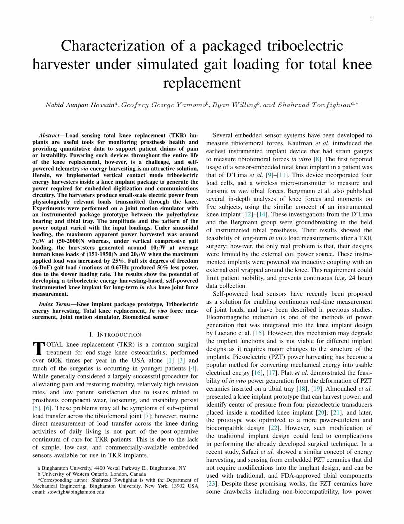
The harvester-package prototypes were tested on a six-degrees-of-freedom (6-DoF) servo-hydraulic joint motion sim-ulator (AMTI VIVO, Watertown, MA, USA). Several exper-iments were performed using the two types of harvester-package assemblies. The harvester configurations for theseassembly types are illustrated in figure 3 (b). As shown infigure 3 (a) each assembly was mounted in between the tibialtray, and the UHMWPE bearing. A size 7 tibial tray (Triathlon,TKR Stryker, Kalamazoo, MI) was secured to a customfixture connected to the lower actuator of the AMTI VIVOjoint simulator using dental cement (Dentstone, Kulzer, LLC,South Bend, IN). A size 7 femoral component was affixedto a femoral component holder designed to interface withthe abduction arm of the AMTI VIVO joint simulator usingpolymethylmethacrylate (PMMA) cement (Bosworth Fastray,Keystone Industries, Myerstown, PA). The energy harvestingsystem was fully assembled by interlocking a 9 mm thickcondylar stabilized (CS) UHMWPE bearing to the superiorsurface of the prototype. The harvesters were connected witha 220MΩ external resistance in parallel for all the experimentsexcept for the one TEG experiments (section III-B), wheneach harvester were measured individually. The voltage, andthe current outputs from the harvesters were measured withKeithley 6514 electrometer. Apparent power outputs are cal-culated by multiplying RMS voltage with corresponding RMScurrent results for Figure 6, 7, and 9. Since current results forthe sinusoidal experiment on flat PDMS harvester were notmeasured, RMS powers (V 2/R) are calculated for Figure 5.A schematic of the experimental setup is shown in Figure 4.
Most of the experiments of this study were performed usingthe compression gait cycle (1-DOF gait) of the joint simulator.It is referred as 1-DOF gait in the rest of the paper. Theother degrees of freedom such as anteroposterior translation
4
(b)(a)
Harvester configuration 2
Harvester configuration 1
PatternedPDMS
Patterned Ti
Patterned Ti
FlatPDMS
Patterned Ti
Flat Ti
Lower actuator
Tibial Tray
Harvester Package
assembly
Femoral component
UHMWPE bearing
Femoral component
holder
Fig. 3. (a) Mounting of a harvester package assembly on the VIVO joint motion simulator. (b) Ti6Al4V made package prototype and two harvesterconfigurations setup on the simulator. Configurations 1 and 2 contain a Ti layer coated with a flat and a patterned PDMS layer at the bottom, respectively.The top layer of the two is the same patterned Ti layer.
AMTI VIVO Joint Simulator
Control and Data Acquisition PC
Measurement out
Resistance
Keithley 6514
Command In
Harvesters electrical connection
Measurement out
Command In
ExceLINX4a
Fig. 4. A schematic of the experimental setup
(AP), mediolateral translation (ML), internal-external rotation(IE), and abduction-adduction (AA) maintained a load of 0Nor 0Nm while the flexion degree of freedom was set to 00.Nevertheless, one assembly was tested under a 6-DoF gait withthe same experimental setup, to compare the electrical outputresults between 6-DoF and 1-DOF gait. The simulated gaitloads used in this study were based on previously measured
tibiofemoral loads [14].The harvester-package prototype assemblies were further
tested under varying magnitudes of sinusoidal, and gait cyclicmotions. While the minimum of the sine forces was keptconstant at 50N for the Ti6Al4V package-harvester assem-blies, the maximum sinusoidal force was varied from 400N to2000N . For gait cyclic experiments, the previously reported

5
0 0.5 1 1.5 2Maximum Sinusoidal Force [KN]
0
2
4
6
8R
MS
Pow
er [
W] Flat PDMS
Patterned PDMS
Fig. 5. RMS power outputs at different maximum sinusoidal loads for theTi6Al4V package-harvesters assemblies. The minimum of the sinusoidal loadswas 50N and the frequency was 1 Hz. Uncertainties on the mean RMS powercalculated from 3 sets of 7 cycles of the corresponding voltage signals areshown in error bars.
average minimum-maximum knee loads of (151 − 1950)Nfrom human walking motions were applied. Additionally,experiments were conducted for a 25% increase and a 25%reduction of the minimum and maximum gait loads.
III. RESULTS
A. Effect of input loads and motions
The effects of different types of input loads, and motions onthe performance of the Ti6Al4V package-harvester configura-tions (Figure 3) are presented here. The RMS power outputsat various maximum sinusoidal loads are shown in Figure 5.Increment of maximum load (400 − 2000)N had statisticalsignificant (p < 0.05; t− test) effect on the harvesters’ poweroutput (0.1 − 7)µW . The power consumption of a previ-ously designed frontend electronic system is approximately5.35µW [43], which enables exclusive powering from theharvester at 2000N . Although there is statistical significant(p < 0.05; t − test) difference between the output from thetwo harvester configurations, it does not follow a linear trendfor the sinusoidal experiment.
The 1-DOF gait variation results are illustrated in Figure6. It shows a quantitative analysis of the apparent poweroutput for the 25% increment, and reduction of the minimum,and the maximum of the gait loads from walking. Whilethe highest apparent power of 20µW was measured for theharvester configuration with flat PDMS at 151 − 2437N , thelowest apparent power of 5µW was found for the harvesterconfiguration with patterned PDMS at 151 − 1462N .
The six-degrees-of-freedom simulator creates a closer toreality gait cycle. The performance of the Ti6Al4V package-harvester setup under a 1-DOF and a 6-DoF gait test aredepicted in Figure 7. The power output under the 6-DoF gaitwas almost 50% less than the power output from the 1-DOFgait test. For 6-DoF gait (Figure 8b), the loads on the packagewere transmitted via 3 translations and 3 rotations at 0.67Hz,and for 1-DOF gait (Figure 8a), the same amount of loads wereapplied at 1Hz in vertical direction only. The corresponding
151-1462 113-1950 151-1950 189-1950 151-2437Min-Max Gait Load [N]
0
5
10
15
20
Ap
par
ent
Pow
er[
W]
Flat PDMS Patterned PDMS
Fig. 6. Apparent power outputs at various 1-DOF gait cycles (period of thesignals = 1 sec) for the Ti6Al4V package-harvesters assemblies. Uncertaintieson the mean apparent power calculated from 3 sets of 7 cycles of thecorresponding voltage and the current signals are shown in error bars.
1-DOF Gait 6-DoF Gait
Min-Max Gait Load [N]
0
2
4
6
8
Ap
pare
nt
Pow
er [
W]
Fig. 7. Apparent power output from a 1-DOF, and a 6-DoF gait test. Testswere performed on the package-harvester configuration 2 (Patterned PDMS)for the load range of 151− 1950N at a frequency of 1Hz, and 0.67Hz forthe 1-DOF and 6-DoF gait, respectively. Uncertainties on the mean apparentpower calculated from 3 sets of 7 cycles of the corresponding voltage and thecurrent signals are shown in error bars.
RMS voltage recorded was 36.97V , and 29.42V for 1-DOF,and 6-DoF gait, respectively (Figure 8c, Figure 8d). The cor-responding RMS current recorded was 0.23µA, and 0.15µAfor 1-DOF, and 6-DoF gait, respectively (Figure 8e, Figure8f).
B. Effect of parallel connection
At 151 − 1950 N of 1-DOF gait loading, the generators atthe medial, and the lateral side of the package compartment foreach Ti6Al4V package-harvester assembly were tested sepa-rately with a 220MΩ external resistance. As shown in Figure9, the apparent power outputs from these individual tests aredistinct, and consistent for the two harvester configurations.Under the same 1-DOF gait, and the same experimental setuptwo TEGs in parallel connection produced more power thanone TEG generated on average for each configuration. Theapparent power harvested from two harvesters in parallel

6
0 1 2 3 4Time [sec]
-2000
-1500
-1000
-500
0V
erti
cal F
orce
[N
]
(a)
1-DOF Gait (151-1950) N
0 1 2 3 4Time [sec]
-2000
-1500
-1000
-500
0
Ver
tica
l For
ce [
N]
(b)
6-DoF Gait (151-1950) N
0 1 2 3Time [sec]
-40
-20
0
20
40
60
Vol
tage
[V
]
(c)
1-DOF Gait (151-1950) N
0 1 2 3Time [sec]
-40
-20
0
20
40
60
Vol
tage
[V
]
(d)
6-DoF Gait (151-1950) N
0 1 2 3Time [sec]
-0.5
0
0.5
1
Cur
rent
[W
]
(e)
1-DOF Gait (151-1950) N
0 1 2 3Time [sec]
-0.5
0
0.5
1
Cur
rent
[W
]
(f)
6-DoF Gait (151-1950) N
Fig. 8. (a)-(b) Force response from the knee simulator under 1-DOF, and 6-DoF gait loading of 151−1950N . (c)-(d) The corresponding voltage measurementfor 1-DOF, and 6-DoF gait loading. (e)-(f) And the respective current measurement for 1-DOF, and 6-DoF gait loading. The input signal frequency was 1Hz,and 0.67Hz for the 1-DOF and the 6-DoF gait tests, respectively.
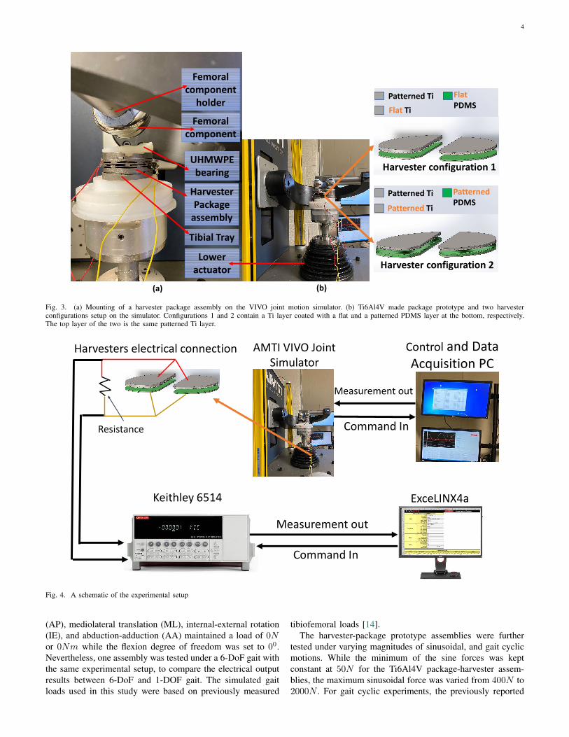
connection is 2.9, and 2.5 times higher than average singleharvester output for the flat, and the patterned PDMS harvesterconfiguration, respectively. The reason for higher output isthat, when two such generators are connected in parallel, theoutput current is increased by some amount that depends onthe internal impedance of the harvesters and the load resistanceof the circuit. The circuit analysis for single, parallel, andseries connection are included in the Appendix. It proves thatthe current and power output across the load resistance fortwo TEGs in parallel is higher than a single TEG.
IV. DISCUSSION AND CONCLUSIONS
In this study, we integrated two vertical contact modetriboelectric energy harvester configurations into a 3D printed
package for measuring tibiofemoral forces in knee implants.Two identical harvesters from each configuration were assem-bled inside the medial and the lateral side of the packagecompartment of the Ti6Al4V package, and placed betweenthe UHMWPE bearing, and the tibial tray of the AMTIVIVO joint motion simulator. Each assembly was tested underdifferent sinusoidal, and walking gait loads. The statisticaldifference observed in the apparent power output with varyingloads between the patterned PDMS, and flat PDMS harvesterconfiguration was below our expectation. Patterned PDMSshould increase the contact surfaces [36], and produce largeroutputs, but, the patterned PDMS harvester generated slightlyless power than the flat PDMS harvester at most sinusoidal andall 1-DOF gaits. This can be due to the fact that the patterned

7
Flat PDMS Patterned PDMSHarvester Configuration
0
5
10
Ap
par
ent
Pow
er [
W] One TEG on average
Two TEGs in parallel connection
Fig. 9. Apparent power output comparison between two harvesters and oneharvester connection. Each test was conducted under 151−1950 N of 1-DOFand 1 Hz frequency. Uncertainties on the mean apparent power calculated from3 sets of 7 cycles of the corresponding voltage and the current signals areshown in error bars.
surfaces of Ti and PDMS are not aligned, which causes arandom engagement of the two surfaces, and can ultimatelycause smaller output. The perfect alignment of two micropatterned surfaces is cumbersome; may deviate over time, andis not advised for total knee replacement applications. As aresult our comparison on the patterned PDMS, and flat PDMSharvester does not follow the expected trends.
For 1-DOF gait experiments, increasing the maximum loadalways significantly (p < 0.05; t− test) increased the outputof the harvester. The minimum load correlates to the initialseparation distance between the two layers of each generator.A lower minimum value shows a larger initial gap, whichshould result in higher output because of the capacitive ef-fect of the harvester. However, we see the highest outputis achieved for the minimum loads of 113 N, 189 N, and151 N, respectively, which do not follow the expected trend.Although these changes in the initial gap were not measuredexperimentally; it is possible that, the gaps were below andabove an optimum. This conclusion is based on our previouswork that showed a gap for which a vertical contact modeTEG produces the maximum power [40]. That is why thepower output in this study did not vary linearly for the differentminimum and the same maximum gait loads.
The apparent power output recorded under the average 1-DOF gait of 151 − 1950N at 1Hz were around 10µW ,which is almost twice the power consumption of 5.32 µWof a previously designed frontend electronic system for theharvester [43]. This property enables powering the processingcircuit entirely from the gait loading, and assures a self-powered system. The harvester-package setup generated evenmore power at higher gait loads. Moreover, we expect thepower to get increased at higher frequencies [38]. Our testingusing the 6-DoF gait had less output than the 1-DOF gaitmainly because of lower frequency selection for the 6-DoFgait test. At lower frequency, the amount of the surface contactbetween the tribolayers of the harvesters at a given time wasless in 6-DoF gait compared to the 1-DOF gait. Since the
surface charge density of a triboelectric generator is directlyproportional to the surface contact area up to a saturation limit[30], the harvesters under 6-DoF gait generated less powerthan the harvesters under 1-DOF gait. However, we believe theharvesters can generate enough power (around 5µW ) requiredfor running a digitization circuitry of a sensor system.
In the future, we will implement a sensor system into theavailable space inside the harvester-package assembly, and testthe in vitro characteristics of the energy harvesting, and thesensing system for simulated activities of daily living.
Some of the limitations of the proposed device are asfollows:
(1) Current methods of harvester installation into the pack-age is lacking perfection. The installation method should bemore managed to allow control over the gap between harvesterlayers inside the package.
(2) It is reported in the literature that, the gap between thetribolayers has effects on the harvesters’ output. However, itwas not possible to measure the gaps once the harvesterswere installed and set for the experiments. Thus, lack ofknowledge about the gap in each of the harvesters in thepackage compartment, is another limitation of this study.Moreover, current procedure of using spacers to reduce thegap is not accurate enough to obtain an optimum gap.
(3) The surface of the PDMS layers can be damagedfrom dynamic contact with the upper Titanium electrode. Thecurrent design is more durable compared to our previous worksbecause of stronger package design. However, the reliabilityand the robustness of the current system will be tested in ourfuture work by testing under millions of cycles. Although byimproving the package strength in the current design, risksof failure have been reduced significantly, it is not resilientagainst failures such as damage of package/harvester materialsin the system [44].
(4) The current design needs to be optimized. Because amore compliant design with a similar energy harvesting systemcan improve the efficiency of the system. However, there is atrade-off limit between the strength and durability of a com-pliant mechanism that can be determined from experimentsor mathematical modeling such as the topology optimizationtechnique [45].
ACKNOWLEDGMENT
This research has been supported by the National Instituteof Arthritis and Musculoskeletal and Skin Diseases of the Na-tional Institute of Health under award number R21AR068572.The content is solely the responsibility of the authors and doesnot necessarily represent the official views of the NationalInstitute of Health. The authors greatly appreciate ProgressiveTool Company that made the Titanium parts.
APPENDIX
The electrical model for a triboelectric harvester can beanalyzed following Niu et al. [46]. The behavior of suchharvester is modeled with three circuit elements: an ac sourcevoltage VM , a variable capacitor CM , and an internal resis-tance r. The variable capacitor CM and the internal resistance

8
Vm1
Cm1
r1
Vm2
Cm2
r2
R
Z1 Z2
1 2
I1
I2IR
R
Vm
Cm
r
I
Z
Vm1
Cm1
r1
Vm2 Cm2 r2
R
Z1Z2
(c)(b)(a)
IO
Fig. 10. Lumped-parameter electrical model for (a) one TEG with an external load resistance, Two TEGs in (b) parallel connection, and (c) series connectionwith an external load resistance.
r are the components of the source impedance Z. In Figure10 the lumped-parameter electrical model of the triboelectricharvester for three different circuit connections are shown. Thetheoretical power output across the load resistance R for eachof the circuit model is derived here.
For one TEG with an external load resistance (Figure 10a)the power output across R is,
P0,single = I2R (1)
Applying KVL, the current I can be obtained as:
IZ + IR+ VM = 0
I = − VMR+ Z
(2)
From equation 1 and 2,
P0,single =
∣∣∣∣ 1
R+ Z
∣∣∣∣2 V 2MR (3)
For two TEGs in parallel with an external load resistance(Figure 10b) the power output across R is,
P0,parallel = I2RR (4)
At node o, IR = I1 + I2 (5)
Applying KVL in loop 1 an 2 the following two equations canbe obtained,
−VM1 − I1Z1 + I2Z2 + VM2 = 0 (6)
−VM2 − I2Z2 − IRR = 0 (7)
Let VM1 = VM2 = VM , Z1 = Z2 = Z as the harvesters areidentical. Thus, equation 5, 6 & 7 can be written in followingmatrix format.[
−Z ZR R+ Z
]I1I2
=
0
−VM
(8)
Solving equation 8, I1 and I2 can be obtained as:I1I2
=
− VM
2R+Z
− VM
2R+Z
(9)
From equation 5 and 9,
IR = − 2VM2R+ Z
(10)
From equation 4 and 10,
P0,parallel =
∣∣∣∣ 1
2R+ Z
∣∣∣∣2 4V 2MR (11)
For two TEGs in series with an external load resistance(Figure 10c) the power output across R is,
P0,series = I2R (12)
Applying KVL, the current I can be obtained as:
−VM1 − IZ1 − VM2 − IZ2 − IR = 0
I = − VM1 + VM1
R+ Z1 + Z2(13)
Set VM1 = VM2 = VM , Z1 = Z2 = Z in equation 13
I = − 2VMR+ 2Z
(14)
From equation 12 and 14,
P0,series =
∣∣∣∣ 1
R+ 2Z
∣∣∣∣2 4V 2MR (15)
9
Set the impedance as
Z = r +1
jωCM= r − j
1
ωCM
and rewrite the power expressions.
From Equation 3,
P0,single =
∣∣∣∣∣ 1
(R+ r) − j( 1ωCM
)
∣∣∣∣∣2
V 2MR
=V 2MR
(R+ r)2 + 1(ωCM )2
(16)
From Equation 11,
P0,parallel =
∣∣∣∣∣ 1
(2R+ r) − j( 1ωCM
)
∣∣∣∣∣2
4V 2MR
=4V 2
MR
(2R+ r)2 + 1(ωCM )2
(17)
From Equation 15,
P0,series =
∣∣∣∣∣ 1
(R+ 2r) − j( 2ωCM
)
∣∣∣∣∣2
4V 2MR
=4V 2
MR
(R+ 2r)2 + 4(ωCM )2
(18)
We choose the external resistance to match the internalresistance (R ≈ r), from equation 16, 17, and 18, it is deducedthat the theoretical power output from two TEGs in parallelconnection is larger than the single and the series connection.
REFERENCES
[1] H. M. Kremers, D. R. Larson, C. S. Crowson, W. K. Kremers, R. E.Washington, C. A. Steiner, W. A. Jiranek, and D. J. Berry, “Prevalenceof total hip and knee replacement in the United States,” The Journalof bone and joint surgery. American volume, vol. 97, no. 17, p. 1386,2015.
[2] A. M. Weinstein, B. N. Rome, W. M. Reichmann, J. E. Collins,S. A. Burbine, T. S. Thornhill, J. Wright, J. N. Katz, and E. Losina,“Estimating the burden of total knee replacement in the United States,”The Journal of bone and joint surgery. American volume, vol. 95, no. 5,p. 385, 2013.
[3] N. B. Jain, L. D. Higgins, D. Ozumba, U. Guller, M. Cronin,R. Pietrobon, and J. N. Katz, “Trends in epidemiology of knee arthro-plasty in the United States, 1990–2000,” Arthritis & Rheumatism,vol. 52, no. 12, pp. 3928–3933, 2005.
[4] S. M. Kurtz, E. Lau, K. Ong, K. Zhao, M. Kelly, and K. J. Bozic, “Futureyoung patient demand for primary and revision joint replacement:national projections from 2010 to 2030,” Clinical Orthopaedics andRelated Research®, vol. 467, no. 10, pp. 2606–2612, 2009.
[5] P. F. Sharkey, P. M. Lichstein, C. Shen, A. T. Tokarski, and J. Parvizi,“Why are total knee arthroplasties failing today—has anything changedafter 10 years?” The Journal of arthroplasty, vol. 29, no. 9, pp. 1774–1778, 2014.
[6] J. Suarez, W. Griffin, B. Springer, T. Fehring, J. B. Mason, and S. Odum,“Why do revision knee arthroplasties fail?” The Journal of arthroplasty,vol. 23, no. 6, pp. 99–103, 2008.
[7] L. D. Dorr and R. A. Boiardo, “Technical considerations in total kneearthroplasty.” Clinical orthopaedics and related research, no. 205, pp.5–11, 1986.
[8] K. R. Kaufman, N. Kovacevic, S. E. Irby, and C. W. Colwell, “Instru-mented implant for measuring tibiofemoral forces,” Journal of biome-chanics, vol. 29, no. 5, pp. 667–671, 1996.
[9] D. D. D’Lima, S. Patil, N. Steklov, J. E. Slamin, and C. W. Colwell Jr,“Tibial forces measured in vivo after total knee arthroplasty,” TheJournal of arthroplasty, vol. 21, no. 2, pp. 255–262, 2006.
[10] D. D. D’Lima, S. Patil, N. Steklov, S. Chien, and C. W. Colwell Jr, “Invivo knee moments and shear after total knee arthroplasty,” Journal ofbiomechanics, vol. 40, pp. S11–S17, 2007.
[11] B. Kirking, J. Krevolin, C. Townsend, C. W. Colwell Jr, and D. D.D’Lima, “A multiaxial force-sensing implantable tibial prosthesis,”Journal of biomechanics, vol. 39, no. 9, pp. 1744–1751, 2006.
[12] I. Kutzner, B. Heinlein, F. Graichen, A. Bender, A. Rohlmann, A. Halder,A. Beier, and G. Bergmann, “Loading of the knee joint during activitiesof daily living measured in vivo in five subjects,” Journal of biomechan-ics, vol. 43, no. 11, pp. 2164–2173, 2010.
[13] I. Kutzner, A. Trepczynski, M. O. Heller, and G. Bergmann, “Kneeadduction moment and medial contact force–facts about their correlationduring gait,” PloS one, vol. 8, no. 12, 2013.
[14] G. Bergmann, A. Bender, F. Graichen, J. Dymke, A. Rohlmann,A. Trepczynski, M. O. Heller, and I. Kutzner, “Standardized loads actingin knee implants,” PloS one, vol. 9, no. 1, 2014.
[15] V. Luciano, E. Sardini, M. Serpelloni, and G. Baronio, “Analysis of anelectromechanical generator implanted in a human total knee prosthesis,”in 2012 IEEE Sensors Applications Symposium Proceedings. IEEE,2012, pp. 1–5.
[16] S. R. Anton and H. A. Sodano, “A review of power harvesting usingpiezoelectric materials (2003–2006),” Smart materials and Structures,vol. 16, no. 3, p. R1, 2007.
[17] W. Yang and S. Towfighian, “A parametric resonator with low thresh-old excitation for vibration energy harvesting,” Journal of Sound andVibration, vol. 446, pp. 129–143, 2019.
[18] S. R. Platt, S. Farritor, K. Garvin, and H. Haider, “The use of piezoelec-tric ceramics for electric power generation within orthopedic implants,”IEEE/ASME transactions on mechatronics, vol. 10, no. 4, pp. 455–461,2005.
[19] S. R. Platt, S. Farritor, and H. Haider, “On low-frequency electricpower generation with PZT ceramics,” IEEE/ASME transactions onMechatronics, vol. 10, no. 2, pp. 240–252, 2005.
[20] S. Almouahed, M. Gouriou, C. Hamitouche, E. Stindel, and C. Roux,“Design and evaluation of instrumented smart knee implant,” IEEETransactions on Biomedical Engineering, vol. 58, no. 4, pp. 971–982,2010.
[21] C. H. E. S. S. Almouahed, M. Gouriou and C. Roux, “The use ofpiezoceramics as electrical energy harvesters within instrumented kneeimplant during walking,” IEEE/ASME Transactions on Mechatronics,vol. 16, no. 5, pp. 799–807, 2011.
[22] S. Almouahed, C. Hamitouche, E. Stindel, and C. Roux, “Optimizationof an instrumented knee implant prototype according to in-vivo userequirements,” in 2013 IEEE Point-of-Care Healthcare Technologies(PHT). IEEE, 2013, pp. 5–8.
[23] M. Safaei, R. M. Meneghini, and S. R. Anton, “Energy harvestingand sensing with embedded piezoelectric ceramics in knee implants,”IEEE/ASME Transactions on Mechatronics, vol. 23, no. 2, pp. 864–874,2018.
[24] Z. L. Wang, “Triboelectric nanogenerators as new energy technology forself-powered systems and as active mechanical and chemical sensors,”ACS nano, vol. 7, no. 11, pp. 9533–9557, 2013.
[25] Q. Zheng, B. Shi, Z. Li, and Z. L. Wang, “Recent progress onpiezoelectric and triboelectric energy harvesters in biomedical systems,”Advanced Science, vol. 4, no. 7, p. 1700029, 2017.
[26] D. J. Lacks and R. M. Sankaran, “Contact electrification of insulatingmaterials,” Journal of Physics D: Applied Physics, vol. 44, no. 45, p.453001, 2011.
[27] W. Zhang, D. Diao, K. Sun, X. Fan, and P. Wang, “Study on friction-electrification coupling in sliding-mode triboelectric nanogenerator,”Nano Energy, vol. 48, pp. 456–463, 2018.
[28] Y. Liu, J. Li, Z. Zhang, X. Hu, and W. Zhang, “Experimental comparisonof five friction models on the same test-bed of the micro stick-slipmotion system,” Mechanical Sciences, vol. 6, no. 1, p. 15, 2015.
[29] C. Jin, D. S. Kia, M. Jones, and S. Towfighian, “On the contactbehavior of micro-/nano-structured interface used in vertical-contact-mode triboelectric nanogenerators,” Nano Energy, vol. 27, pp. 68–77,2016.
[30] N. A. Hossain, M. J. Razavi, and S. Towfighian, “Analysis of mechanicaldeformation effect on the voltage generation of a vertical contact mode

10
triboelectric generator,” Journal of Micromechanics and Microengineer-ing, 2020.
[31] Z. L. Wang, “On Maxwell’s displacement current for energy and sensors:the origin of nanogenerators,” Materials Today, vol. 20, no. 2, pp. 74–82,2017.
[32] A. Ibrahim, A. Ramini, and S. Towfighian, “Experimental and theo-retical investigation of an impact vibration harvester with triboelectrictransduction,” Journal of Sound and Vibration, vol. 416, pp. 111–124,2018.
[33] D. Nelson, A. Ibrahim, and S. Towfighian, “Dynamics of a thresholdshock sensor: Combining bi-stability and triboelectricity,” Sensors andActuators A: Physical, vol. 285, pp. 666–675, 2019.
[34] M.-L. Seol, S.-H. Lee, J.-W. Han, D. Kim, G.-H. Cho, and Y.-K.Choi, “Impact of contact pressure on output voltage of triboelectricnanogenerator based on deformation of interfacial structures,” NanoEnergy, vol. 17, pp. 63–71, 2015.
[35] L. Lin, Y. Xie, S. Wang, W. Wu, S. Niu, X. Wen, and Z. L. Wang,“Triboelectric active sensor array for self-powered static and dynamicpressure detection and tactile imaging,” ACS nano, vol. 7, no. 9, pp.8266–8274, 2013.
[36] F.-R. Fan, L. Lin, G. Zhu, W. Wu, R. Zhang, and Z. L. Wang, “Trans-parent triboelectric nanogenerators and self-powered pressure sensorsbased on micropatterned plastic films,” Nano letters, vol. 12, no. 6, pp.3109–3114, 2012.
[37] M. S. Rasel, P. Maharjan, M. Salauddin, M. T. Rahman, H. O. Cho,J. W. Kim, and J. Y. Park, “An impedance tunable and highly efficienttriboelectric nanogenerator for large-scale, ultra-sensitive pressure sens-ing applications,” Nano Energy, vol. 49, pp. 603–613, 2018.
[38] A. Ibrahim, M. Jain, E. Salman, R. Willing, and S. Towfighian, “A smartknee implant using triboelectric energy harvesters,” Smart Materials andStructures, vol. 28, no. 2, p. 025040, 2019.
[39] A. Ibrahim, G. Yamomo, R. Willing, and S. Towfighian, “Analysis ofa triboelectric energy harvester for total knee replacements under gaitloading,” in Active and Passive Smart Structures and Integrated SystemsXII, vol. 10967. International Society for Optics and Photonics, 2019,p. 109671D.
[40] A. Ibrahim, G. Yamomo, Willing, T. Ryan, and Shahrzad, “ParametricStudy of Triboelectric Transducer in Total Knee Replacement Applica-tion,” Journal of Intelligent Material Systems and Structures, 2020.
[41] G. Yamomo, “Design and Analysis of a Compliant 3D Printed EnergyHarvester Package for Knee Implants,” Electronic Thesis and Disserta-tion Repository. 6728, https://ir.lib.uwo.ca/etd/6728.
[42] S. Teoh, “Fatigue of biomaterials: a review,” International journal offatigue, vol. 22, no. 10, pp. 825–837, 2000.
[43] M. Jain, A. Ibrahim, E. Salman, M. Stanacevic, R. Willing, andS. Towfighian, “Frontend Electronic System for Triboelectric Harvesterin a Smart Knee Implant,” in 2019 IEEE 62nd International MidwestSymposium on Circuits and Systems (MWSCAS). IEEE, 2019, pp. 386–389.
[44] W. Zhang and C. Van Luttervelt, “Toward a resilient manufacturingsystem,” CIRP annals, vol. 60, no. 1, pp. 469–472, 2011.
[45] L. Cao, A. T. Dolovich, A. Chen, and W. C. Zhang, “Topologyoptimization of efficient and strong hybrid compliant mechanisms usinga mixed mesh of beams and flexure hinges with strength control,”Mechanism and Machine Theory, vol. 121, pp. 213–227, 2018.
[46] S. Niu, Y. S. Zhou, S. Wang, Y. Liu, L. Lin, Y. Bando, and Z. L. Wang,“Simulation method for optimizing the performance of an integratedtriboelectric nanogenerator energy harvesting system,” Nano Energy,vol. 8, pp. 150–156, 2014.
Nabid Aunjum Hossain received his B.S. degreein mechanical engineering from the BangladeshUniversity of Engineering and Technology (BUET),Dhaka, Bangladesh, in 2016. In 2017 he joinedthe mechanical engineering department of SUNYBinghamton, Binghamton, NY, USA, where he hasbeen working towards his PhD degree. His researchinterests are in electro-mechanical systems, vibrationand energy harvesting. Currently his focus is ondeveloping a triboelectric energy harvesting based,self-powered instrumented knee implant.
Geofrey Yamomo received his BESc and MEScdegrees in mechanical engineering from the Univer-sity of Western Ontario in London, Ontario, Canadain 2017 and 2020, respectively. His research workcovered the design and analysis of orthopaedic im-plants. He is a member of the Canadian Society forMechanical Engineering (CSME).
Ryan Willing completed his PhD in MechanicalEngineering at Queen’s University in 2010 and apost-doc at Western University in 2013. He is anAssistant Professor in Mechanical and MaterialsEngineering and Biomedical Engineering at WesternUniversity, a member of Western’s Bone and JointInstitute, and a Scientist with the Lawson HealthResearch Institute.
Dr. Shahrzad Towfighian Shahrzad Towfighian re-ceived the B.S. degree from the Amirkabir Univer-sity of Technology, Iran, in 2001, the M.S. degreefrom Ryerson University, Canada, in 2006, andthe Ph.D. degree from the University ofWaterloo,Canada, in 2011. She joined the Mechanical Engi-neering Department, State University of New Yorkat Binghamton, in Fall 2013. Her research inter-ests are microelectromechanical systems and energyharvesting for bio-medical devices. She focuses oncreating theoretical and experimental frameworks to
explain the underlying mechanism of electro-mechanical systems. Using theseframeworks, she seeks innovative methods to improve functionality of devicesfor various applications. She was a recipient of several grants from theNational Science Foundation and the National Health Institute.