Characteristics of Ejectors on Small Gas Turbine · PDF fileCHARACTERISTICS OF EJECTORS ON...
7
CHARACTERISTICS OF EJECTORS ON SMALL GAS TURBINE ENGINES J. Georgi, S. Staudacher Institute of Aircraft Propulsion Systems University of Stuttgart Pfaffenwaldring 6, 70569 Stuttgart, Germany Abstract Unmanned, scaled flight demonstrators are used to investigate new airplane designs. The demonstrators are generally driven by small jet engines because jet engines are also used for airplanes. Small jet engine designs may include a fan, an aft-fan, a geared fan or an ejector. Ejector design has the advantage of low weight and simplicity. We examined the characteristics of a small jet engine with ejector, first qualitatively, using a water channel and then quantitatively, using a test rig. The experimental setups and the gathered test data are briefly presented. NOMENCLATURE A Area F Force L Length Ma Mach number T Temperature c Coefficient d Diameter h Water height ˙ m Mass flow p Pressure v Velocity ε Area ratio ζ Velocity ratio λ Length ratio ρ Density φ Thrust augmentation Indices BPR Bypass ratio D Flow rate DK Pressure force FK Spring force G Gross N Net a Average ej With ejector f Flight id Ideal in Inlet l Local t Total 0 Ambient 5 Nozzle primar flow entry 60 Ejector primary flow entry / mixing plane 61 Ejector secondary flow entry 9 Ejector exit 1. INTRODUCTION Unmanned, scaled flight demonstrators are used to examine new airplane configurations. They are driven by small jet engines in the thrust class between 15 and 500 N. They are preferred to propeller drives because of the desired similarity to the original aircraft. Examples for the scaled flight demonstrators are the experimental airplanes in the projects NACRE and VELA2 as described by Nguewo [1]. They should provide insights into the aerodynamic and aero- mechanical properties of the original aircraft. The flight speed of such vehicles is limited by the requirement for similar flight performance. Here Mach numbers up to Ma = 0.2 are achieved. The resulting ratio between jet and flight speed is not similar to the original aircraft. This results in a jet spreading that differs from the original one and affects the airflow around the wings and the flaps [2]. In order to minimize these differences, small jet engines with a bypass-ratio should be used in scaled flight demonstrators. Feasible designs, such as fan, aft-fan, geared fan, two-shaft turbofan or ejector differ in complexity, power, weight and optimal operating range. The focus of this work lies on the study of ejectors, because they offer the advantages of small weight and low complexity. Moreover, ejectors on small jet engines have not been a subject of scientific investigations. They differ in size and similarity parameters from previous studies. 2. EJECTOR OPERATION An ejector is a jet pump without moving parts, see Fig. 1. It can be defined by a nozzle of the area A60 and of a constant cross-section mixing chamber of the area A9 and length L. Shear forces between the primary and secondary flow cause a mixing process of both streams and a static pressure drop below ambient pressure in the mixing plane [3] [4]. Energy is transferred between the flows. The kinetic energy of the primary stream is distributed on a larger mass flow of air. The specific enthalpies of the two streams equalize and the ejector exhaust velocity v9 decreases. For this reason propulsive efficiency increases. As a result thrust augmentation can be achieved [5]. This Deutscher Luft- und Raumfahrtkongress 2013 DocumentID: 301339 1
Transcript of Characteristics of Ejectors on Small Gas Turbine · PDF fileCHARACTERISTICS OF EJECTORS ON...
CHARACTERISTICS OF EJECTORS ON SMALL GAS TURBINE ENGINES
J. Georgi, S. StaudacherInstitute of Aircraft Propulsion Systems
University of StuttgartPfaffenwaldring 6, 70569 Stuttgart, Germany
AbstractUnmanned, scaled flight demonstrators are used to investigate new airplane designs. The demonstrators aregenerally driven by small jet engines because jet engines are also used for airplanes. Small jet engine designsmay include a fan, an aft-fan, a geared fan or an ejector. Ejector design has the advantage of low weight andsimplicity.We examined the characteristics of a small jet engine with ejector, first qualitatively, using a water channel andthen quantitatively, using a test rig. The experimental setups and the gathered test data are briefly presented.
NOMENCLATURE
A AreaF ForceL LengthMa Mach numberT Temperaturec Coefficientd Diameterh Water heightm Mass flowp Pressurev Velocityε Area ratioζ Velocity ratioλ Length ratioρ Densityφ Thrust augmentation
IndicesBPR Bypass ratioD Flow rateDK Pressure forceFK Spring forceG GrossN Neta Averageej With ejectorf Flightid Idealin Inletl Localt Total0 Ambient5 Nozzle primar flow entry60 Ejector primary flow entry / mixing plane61 Ejector secondary flow entry9 Ejector exit
1. INTRODUCTION
Unmanned, scaled flight demonstrators are used to examinenew airplane configurations. They are driven by small jetengines in the thrust class between 15 and 500 N. Theyare preferred to propeller drives because of the desiredsimilarity to the original aircraft. Examples for the scaledflight demonstrators are the experimental airplanes in theprojects NACRE and VELA2 as described by Nguewo [1].They should provide insights into the aerodynamic and aero-mechanical properties of the original aircraft. The flightspeed of such vehicles is limited by the requirement forsimilar flight performance. Here Mach numbers up to Ma =0.2 are achieved.The resulting ratio between jet and flight speed is not similarto the original aircraft. This results in a jet spreading thatdiffers from the original one and affects the airflow aroundthe wings and the flaps [2]. In order to minimize thesedifferences, small jet engines with a bypass-ratio should beused in scaled flight demonstrators. Feasible designs, suchas fan, aft-fan, geared fan, two-shaft turbofan or ejector differin complexity, power, weight and optimal operating range.The focus of this work lies on the study of ejectors, becausethey offer the advantages of small weight and low complexity.Moreover, ejectors on small jet engines have not been asubject of scientific investigations. They differ in size andsimilarity parameters from previous studies.
2. EJECTOR OPERATION
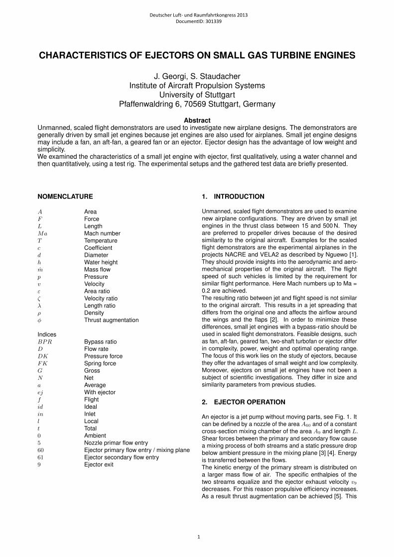
An ejector is a jet pump without moving parts, see Fig. 1. Itcan be defined by a nozzle of the area A60 and of a constantcross-section mixing chamber of the area A9 and length L.Shear forces between the primary and secondary flow causea mixing process of both streams and a static pressure dropbelow ambient pressure in the mixing plane [3] [4]. Energyis transferred between the flows.The kinetic energy of the primary stream is distributed ona larger mass flow of air. The specific enthalpies of thetwo streams equalize and the ejector exhaust velocity v9decreases. For this reason propulsive efficiency increases.As a result thrust augmentation can be achieved [5]. This
Deutscher Luft- und Raumfahrtkongress 2013DocumentID: 301339
1
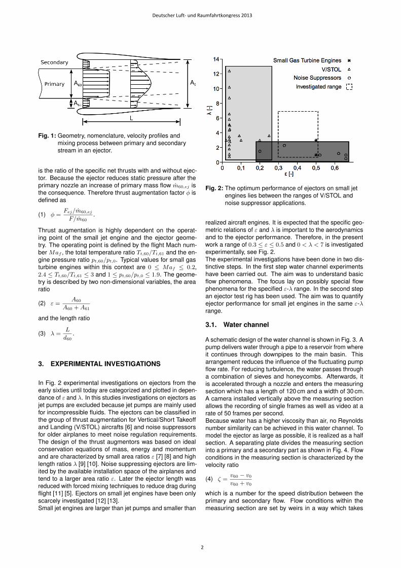
Fig. 1: Geometry, nomenclature, velocity profiles andmixing process between primary and secondarystream in an ejector.
is the ratio of the specific net thrusts with and without ejec-tor. Because the ejector reduces static pressure after theprimary nozzle an increase of primary mass flow m60,ej isthe consequence. Therefore thrust augmentation factor φ isdefined as
(1) φ =Fej/m60,ej
F/m60.
Thrust augmentation is highly dependent on the operat-ing point of the small jet engine and the ejector geome-try. The operating point is defined by the flight Mach num-ber Maf , the total temperature ratio Tt,60/Tt,61 and the en-gine pressure ratio pt,60/pt,0. Typical values for small gasturbine engines within this context are 0 ≤ Maf ≤ 0.2,2.4 ≤ Tt,60/Tt,61 ≤ 3 and 1 ≤ pt,60/pt,0 ≤ 1.9. The geome-try is described by two non-dimensional variables, the arearatio
(2) ε =A60
A60 +A61
and the length ratio
(3) λ =L
d60.
3. EXPERIMENTAL INVESTIGATIONS
In Fig. 2 experimental investigations on ejectors from theearly sixties until today are categorized and plotted in depen-dance of ε and λ. In this studies investigations on ejectors asjet pumps are excluded because jet pumps are mainly usedfor incompressible fluids. The ejectors can be classified inthe group of thrust augmentation for Vertical/Short Takeoffand Landing (V/STOL) aircrafts [6] and noise suppressorsfor older airplanes to meet noise regulation requirements.The design of the thrust augmentors was based on idealconservation equations of mass, energy and momentumand are characterized by small area ratios ε [7] [8] and highlength ratios λ [9] [10]. Noise suppressing ejectors are lim-ited by the available installation space of the airplanes andtend to a larger area ratio ε. Later the ejector length wasreduced with forced mixing techniques to reduce drag duringflight [11] [5]. Ejectors on small jet engines have been onlyscarcely investigated [12] [13].Small jet engines are larger than jet pumps and smaller than
Fig. 2: The optimum performance of ejectors on small jetengines lies between the ranges of V/STOL andnoise suppressor applications.
realized aircraft engines. It is expected that the specific geo-metric relations of ε and λ is important to the aerodynamicsand to the ejector performance. Therefore, in the presentwork a range of 0.3 ≤ ε ≤ 0.5 and 0 < λ < 7 is investigatedexperimentally, see Fig. 2.The experimental investigations have been done in two dis-tinctive steps. In the first step water channel experimentshave been carried out. The aim was to understand basicflow phenomena. The focus lay on possibly special flowphenomena for the specified ε-λ range. In the second stepan ejector test rig has been used. The aim was to quantifyejector performance for small jet engines in the same ε-λrange.
3.1. Water channel
A schematic design of the water channel is shown in Fig. 3. Apump delivers water through a pipe to a reservoir from whereit continues through downpipes to the main basin. Thisarrangement reduces the influence of the fluctuating pumpflow rate. For reducing turbulence, the water passes througha combination of sieves and honeycombs. Afterwards, itis accelerated through a nozzle and enters the measuringsection which has a length of 120 cm and a width of 30 cm.A camera installed vertically above the measuring sectionallows the recording of single frames as well as video at arate of 50 frames per second.Because water has a higher viscosity than air, no Reynoldsnumber similarity can be achieved in this water channel. Tomodel the ejector as large as possible, it is realized as a halfsection. A separating plate divides the measuring sectioninto a primary and a secondary part as shown in Fig. 4. Flowconditions in the measuring section is characterized by thevelocity ratio
(4) ζ =v60 − v0v60 + v0
which is a number for the speed distribution between theprimary and secondary flow. Flow conditions within themeasuring section are set by weirs in a way which takes
Deutscher Luft- und Raumfahrtkongress 2013
2

Fig. 3: Schematic design of the water channel.
care that during a series of measurements the overall massflow and the water height h remain constant. Therefore,for each velocity ratio within a series of measurements thesame average flow velocity va is given. On this average flowvelocity an average Reynolds number
(5) Rea =vah
ν.
is established. Under these conditions two measurementseries at constant average Reynolds numbers of Rea = 2770and 10250 at a constant water height of h = 0.11 m in themeasuring section were carried out.
Fig. 4: Measuring section with separating plane, variableejector geometry and weirs.
The flow around the trailing edge of the separating platewas visualized for two cases: with and without ejector. Adiluted ink solution was injected into the boundary layersof the separating plate. The resulting mixing cone can bedisplayed by superpositioning of frames. The mixing is char-acterized geometrically by two parameters. The openingangle α describes the spreading of the mixing zone andthus is a measure for the mixing intensity. The deflectionangle β is the angle between the bisection of the openingangle and the extension of the separating plate. It describesthe deflection of the mixing cone relative to the main flowdirection, see Fig. 5. The angles were evaluated by averag-ing multiple measurements. Gross errors were treated asdescribed in [14].The opening angles for the case without ejector were mea-sured by Strehblow [15]. The results are compared to datafrom earlier experimental mixer investigations by Banzhaf[16] at the same water channel with a similar geometricsetup, see Fig. 6. For small Rea and ζ = 0 no mixing oc-curs. If we increase Rea, a Karman vortex street is formedand an opening angle can be measured. The frequency of
Fig. 5: Superimposing of multiple individual frames andevaluation of opening and deflection angle [15].
the Karman vortex street depends on the thickness of thetrailing edge and Rea. With increasing velocity ratio ζ Kelvin-Helmholtz vortices occur, causing an intense mixing of coreand ambient flow. It was observed that for ζ > 0.5 the open-ing angle α increases linearly as described by Sabin [17].The Flow angle β indicates a slight deflection towards thefaster stream.
Fig. 6: Comparison of free jet opening angles after aseparating plate at different average Reynoldsnumbers. Series A1-A4 were done by Banzhaf [16].
In further series of experiments at an average Reynoldsnumber of Rea = 10250 a variable ejector was involved. Forthe constant length ratio of λ = 1.69 and velocity ratios of ζ =0.53 and 0.68 the ejector area ratio ε was varied, see Fig. 7.It was observed that opening angles for all measurementsare smaller with ejector than without it. Moreover, the open-ing angles depend on the area ratio. For increasing arearatio the opening angles decrease.Ahmed [18] mentioned that wall effect is one of the reasonsfor the decreasing mixing layer growth. Thus an increasingarea ratio leads to more confinement of the flow which de-creases the opening angles.Moreover, for constant area ratio and length ratio with in-creasing velocity ratio the slope of the curves decreases,see Fig. 8. The difference in opening angles between thefree jet and within the ejector increases with increasing veloc-ity ratio. This effect can be explained with ejector pumping.Within the ejector a local velocity parameter ζl can be formed
Deutscher Luft- und Raumfahrtkongress 2013
3
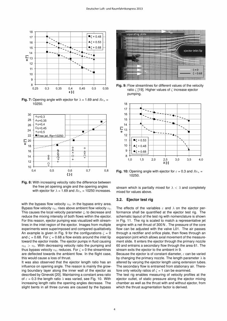
Fig. 7: Opening angle with ejector for λ = 1.69 and Rea =10250.
Fig. 8: With increasing velocity ratio the difference betweenthe free jet opening angle and the opening angleswith ejector for λ = 1.69 and Rea = 10250 increases.
with the bypass flow velocity v61 in the bypass entry area.Bypass flow velocity v61 rises above ambient flow velocity v0.This causes the local velocity parameter ζl to decrease andreduce the mixing intensity of both flows within the ejector.For this reason, ejector pumping was visualized with stream-lines in the inlet region of the ejector. Images from multipleexperiments were superimposed and compared qualitatively.An example is given in Fig. 9 for the configurations ζ = 0and ζ = 0.68. For ζ = 0.68 a flow exists around the inlet liptoward the ejector inside. The ejector pumps in fluid causingv61 > v0. With decreasing velocity ratio the pumping andthus bypass velocity v61 reduces. For ζ = 0 the streamlinesare deflected towards the ambient flow. In the flight case,this would cause a loss of thrust.It was also observed that the ejector length ratio has aninfluence on opening angle. The reason is mainly the grow-ing boundary layer along the inner wall of the ejector asdescribed by Ginevski [20]. Maintaining a constant area ratioof ε = 0.3 the length ratio λ was varied, see Fig. 10. Withincreasing length ratio the opening angles decrease. Theslight bents in all three curves are caused by the bypass
Fig. 9: Flow streamlines for different values of the velocityratio ζ [19]. Higher values of ζ increase ejectorpumping.
Fig. 10: Opening angle with ejector for ε = 0.3 and Rea =10250.
stream which is partially mixed for λ < 3 and completelymixed for values above.
3.2. Ejector test rig
The effects of the variables ε and λ on the ejector per-formance shall be quantified at the ejector test rig. Theschematic layout of the test rig with nomenclature is shownin Fig. 11. The rig is scaled to match a representative jetengine with a net thrust of 300 N . The pressure of the coreflow can be adjusted with the valve L01. The air passesthrough a rectifier and orifice plate, then flows through anexpansion joint which allows axial movement of the measure-ment slide. It enters the ejector through the primary nozzle60 and entrains a secondary flow through the area 61. Thestream exits the ejector to the ambient in 9.Because the ejector is of constant diameter, ε can be variedby changing the primary nozzle. The length parameter λ isaltered by varying the ejector length using extension tubes.The secondary flow is entrained from stationary air. There-fore only velocity ratios of ζ = 1 can be examined.The test rig enables measuring of velocity profiles at theejector outlet, of static pressure along the ejector mixingchamber as well as the thrust with and without ejector, fromwhich the thrust augmentation factor is derived.
Deutscher Luft- und Raumfahrtkongress 2013
4
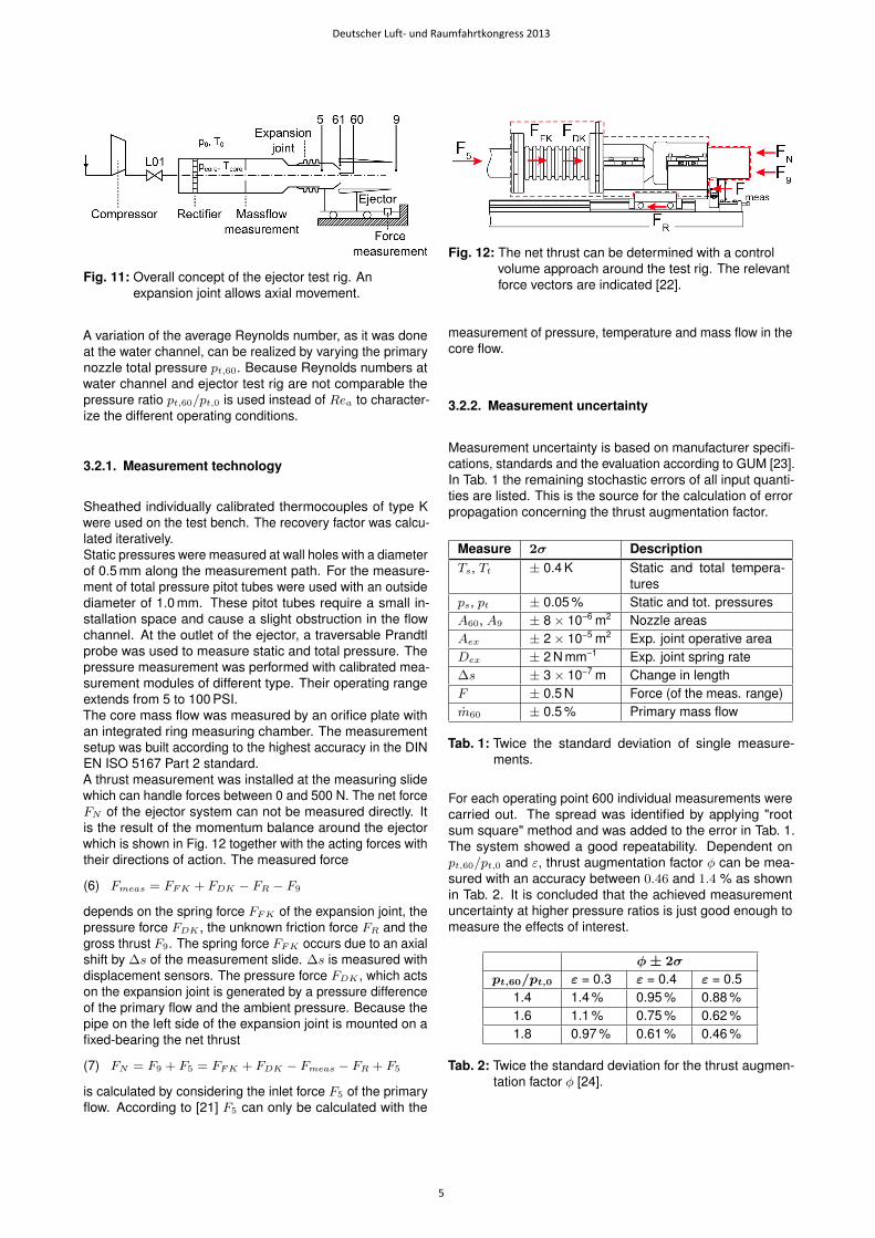
Fig. 11: Overall concept of the ejector test rig. Anexpansion joint allows axial movement.
A variation of the average Reynolds number, as it was doneat the water channel, can be realized by varying the primarynozzle total pressure pt,60. Because Reynolds numbers atwater channel and ejector test rig are not comparable thepressure ratio pt,60/pt,0 is used instead of Rea to character-ize the different operating conditions.
3.2.1. Measurement technology
Sheathed individually calibrated thermocouples of type Kwere used on the test bench. The recovery factor was calcu-lated iteratively.Static pressures were measured at wall holes with a diameterof 0.5 mm along the measurement path. For the measure-ment of total pressure pitot tubes were used with an outsidediameter of 1.0 mm. These pitot tubes require a small in-stallation space and cause a slight obstruction in the flowchannel. At the outlet of the ejector, a traversable Prandtlprobe was used to measure static and total pressure. Thepressure measurement was performed with calibrated mea-surement modules of different type. Their operating rangeextends from 5 to 100 PSI.The core mass flow was measured by an orifice plate withan integrated ring measuring chamber. The measurementsetup was built according to the highest accuracy in the DINEN ISO 5167 Part 2 standard.A thrust measurement was installed at the measuring slidewhich can handle forces between 0 and 500 N. The net forceFN of the ejector system can not be measured directly. Itis the result of the momentum balance around the ejectorwhich is shown in Fig. 12 together with the acting forces withtheir directions of action. The measured force
(6) Fmeas = FFK + FDK − FR − F9
depends on the spring force FFK of the expansion joint, thepressure force FDK , the unknown friction force FR and thegross thrust F9. The spring force FFK occurs due to an axialshift by ∆s of the measurement slide. ∆s is measured withdisplacement sensors. The pressure force FDK , which actson the expansion joint is generated by a pressure differenceof the primary flow and the ambient pressure. Because thepipe on the left side of the expansion joint is mounted on afixed-bearing the net thrust
(7) FN = F9 + F5 = FFK + FDK − Fmeas − FR + F5
is calculated by considering the inlet force F5 of the primaryflow. According to [21] F5 can only be calculated with the
Fig. 12: The net thrust can be determined with a controlvolume approach around the test rig. The relevantforce vectors are indicated [22].
measurement of pressure, temperature and mass flow in thecore flow.
3.2.2. Measurement uncertainty
Measurement uncertainty is based on manufacturer specifi-cations, standards and the evaluation according to GUM [23].In Tab. 1 the remaining stochastic errors of all input quanti-ties are listed. This is the source for the calculation of errorpropagation concerning the thrust augmentation factor.
Measure 2σ DescriptionTs, Tt ± 0.4 K Static and total tempera-
turesps, pt ± 0.05 % Static and tot. pressuresA60, A9 ± 8 × 10⁻⁶ m2 Nozzle areasAex ± 2 × 10⁻⁵ m2 Exp. joint operative areaDex ± 2 N mm−1 Exp. joint spring rate∆s ± 3 × 10⁻⁷ m Change in lengthF ± 0.5 N Force (of the meas. range)m60 ± 0.5 % Primary mass flow
Tab. 1: Twice the standard deviation of single measure-ments.
For each operating point 600 individual measurements werecarried out. The spread was identified by applying "rootsum square" method and was added to the error in Tab. 1.The system showed a good repeatability. Dependent onpt,60/pt,0 and ε, thrust augmentation factor φ can be mea-sured with an accuracy between 0.46 and 1.4 % as shownin Tab. 2. It is concluded that the achieved measurementuncertainty at higher pressure ratios is just good enough tomeasure the effects of interest.
φ± 2σ
pt,60/pt,0 ε = 0.3 ε = 0.4 ε = 0.51.4 1.4 % 0.95 % 0.88 %1.6 1.1 % 0.75 % 0.62 %1.8 0.97 % 0.61 % 0.46 %
Tab. 2: Twice the standard deviation for the thrust augmen-tation factor φ [24].
Deutscher Luft- und Raumfahrtkongress 2013
5
3.2.3. Measurements
Thirty different geometrical combinations including five arearatios with 0.3 ≤ ε ≤ 0.5 and six length ratios with 1.71 ≤λ ≤ 6.59 have been investigated. For each combination sixnozzle pressure ratios pt,60/p0 between 1.6 and 1.9 wereinvestigated.
Fig. 13: Contours of thrust augmentation factor for a nozzlepressure ratio of 1.6.
Fig. 14: Contours of thrust augmentation factor for a nozzlepressure ratio of 1.8.
In Fig. 13 and Fig. 14 thrust augmentation factor is shown asfunction of the geometric parameters for a nozzle pressureratio of respectively 1.6 and 1.8 in the form of a contour plot.
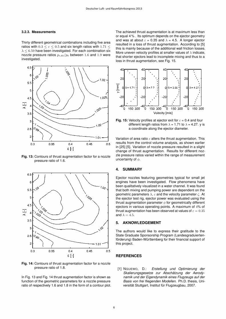
The achieved thrust augmentation is at maximum less thanor equal 4 % . Its optimum depends on the ejector geometryand was at about ε = 0.35 and λ = 4.5. A longer ejectorresulted in a loss of thrust augmentation. According to [5]this is mainly because of the additional wall friction losses.More uneven velocity profiles at smaller values of λ indicate,that shorter ejectors lead to incomplete mixing and thus to aloss in thrust augmentation, see Fig. 15.
Fig. 15: Velocity profiles at ejector exit for ε = 0.4 and fourdifferent length ratios from λ = 1.71 to λ = 4.27. y isa coordinate along the ejector diameter.
Variation of area ratio ε alters the thrust augmentation. Thisresults from the control volume analysis, as shown earlierin [25] [5]. Variation of nozzle pressure resulted in a slightchange of thrust augmentation. Results for different noz-zle pressure ratios varied within the range of measurementuncertainty of φ.
4. SUMMARY
Ejector nozzles featuring geometries typical for small jetengines have been investigated. Flow phenomena havebeen qualitatively visualized in a water channel. It was foundthat both mixing and pumping power are dependent on thegeometric parameters λ, ε and the velocity parameter ζ. Atthe ejector test rig, ejector power was evaluated using thethrust augmentation parameter φ for geometrically differentejectors in various operating points. A maximum of 4% ofthrust augmentation has been observed at values of ε = 0.35and λ = 4.5.
5. AKNOWLEDGEMENT
The authors would like to express their gratitude to theState Graduate Sponsorship Program (Landesgraduierten-förderung) Baden-Württemberg for their financial support ofthis project.
REFERENCES
[1] NGUEWO, D.: Erstellung und Optimierung derSkalierungsgesetze zur Abschätzung der Aerody-namik und der Eigendynamik eines Flugzeugs auf derBasis von frei fliegenden Modellen. Ph.D. thesis, Uni-versität Stuttgart, Institut für Flugzeugbau, 2007.
Deutscher Luft- und Raumfahrtkongress 2013
6

[2] KUPCIS, E.: The results of a low-speed wind tunneltest to investigate the effects of the Refan JT8D en-gine target thrust reverser on the stability and controlcharacteristics of the Boeing 727-200 airplane. (1974).
[3] HUANG, B.; CHANG, J.; WANG, C.; PETRENKO, V.: A 1-D analysis of ejector performance. Tech. Rep. 354-364,1998.
[4] CAMPBELL, W.; VON OHAIN, H.: Thrust Augmenta-tion for V/STOL. Tech. Rep. ARL 67-0065, EnergeticsResearch Laboratoy, 1967.
[5] PRESZ, W.; REYNOLDS, G.; HUNTER, C.: ThrustAugmentation with Mixer/Ejector Systems. 40thAIAA Aerospace Sciences Meeting and Exhibit,(2002)(2002-0230).
[6] NAGARAJA, K.: Advances in Ejector Technology - ATribute to Hans von Ohain’s Vision. Air Force WrightAeronautical Laboratories Flight Dynamics LaboratoryWright-Patterson Air Force Base, Ohio, (1982).
[7] ALPERIN, M.; WU, J.J.: Thrust augmenting ejectors,part I. AIAA journal, vol. 21 (1983)(10) pp. 1428–1436.
[8] ALPERIN, M.; WU, J.J.: Thrust augmenting ejectors, II.AIAA journal, vol. 21 (1983)(12) pp. 1698–1706.
[9] QUINN, B.: Ejector performance at high temperaturesand pressures. Journal of Aircraft, vol. 13 (1976)(12)pp. 948–954.
[10] YANG, T.T.; NTONE, F.; JIANG, T.; PITTS, D.: An in-vestigation of high performance, short thrust augment-ing ejectors. Journal of fluids engineering, vol. 107(1985)(1) pp. 23–30.
[11] PRESZ, W.M.; MORIN, B.K.L.; GOUSY, R.G.: Forcedmixer lobes in ejector designs. Journal of Propulsionand Power, vol. 4 (1988)(4) pp. 350–355.
[12] HACKADAY, G.L.: Thrust Augmentation for a SmallTurbojet Engine. Tech. rep., DTIC Document, 1999.
[13] RIEDEBERGER, D.: Design, Implementation and Eval-uation of a Passive Thrust Augmentation Device forthe SR-30 Turbojet. Research paper, Institut of AircraftPropulsion Systems (ILA), Stuttgart University, (2010).
[14] BAUER, M.: Modulares Leistungsberechnungsver-fahren zur automatisierten modellbasierten Leistungs-analyse von Gasturbinen. Ph.D. thesis, Institut für Luft-fahrtantriebe der Universität Stuttgart, 2005.
[15] STREHBLOW, D.: Experimentelle Untersuchungen amWasserkanal zu Mischungsvorgängen in Ejektoren.Research paper, Institut für Luftfahrtantriebe der Uni-versität Stuttgart, 2013.
[16] BANZHAF, B.: Untersuchungen zum Betriebsverhaltengemischter Abgassysteme in Luftstrahltriebwerken im
niedrigen Lastbereich. Ph.D. thesis, Institut für Luft-fahrtantriebe der Universität Stuttgart, 2009.
[17] SABIN, C.M.: An analytical and experimental study ofthe plane, incompressible, turbulent free-shear layerwith arbitrary velocity ratio and pressure gradient. Jour-nal of Basic Engineering, vol. 87 (1965) p. 421.
[18] AHMED, M.; SHARMA, S.: Effect of velocity ratio on theturbulent mixing of confined, co-axial jets. Experimentalthermal and fluid science, vol. 22 (2000)(1) pp. 19–33.
[19] JOUNBLAT, R.: Visualisierung der Strömung von Ejek-toren im Wasserkanal. Research paper, Institut fürLuftfahrtantriebe der Universität Stuttgart, 2013.
[20] GINEVSKI, A.: Theory of Turbulent Jets and Wakes inRussian. Mashinostroenie, Moscow, vol. 32 (1969).
[21] BOHL, W.; ELMENDORF, W.: Technische Strö-mungslehre. Vogel Verlag, 2005.
[22] REIZE, F.: Planung, Konstruktion und Aufbau einesEjektorprüfstandes zur Validierung des SAEPP Ejek-tormoduls und der numerischen Strömungssimulation.Master’s thesis, Institut für Luftfahrtantriebe der Univer-sität Stuttgart, 2013.
[23] JOINT COMMITTEE FOR GUIDES IN METROLOGY: Eval-uation of measurement data - An introduction to the’Guide to the expression of uncertainty in measure-ment’, Deutsche Fassung Auswertung von Messdaten- Eine Einführung zum ’Leitfaden zur Angabe der Un-sicherheit beim Messen’. BIPM, (2009).
[24] RAMIN, S.: Erweiterung eines Ejektorprüfstands zurBestimmung des Betriebsverhaltens eines geometrischvariablen Ejektors. Research paper, Institut of AircraftPropulsion Systems (ILA), Stuttgart University, (2013).
[25] GEORGI, J.; STAUDACHER, S.; FALALEEV, S.: Mod-elling of an Ejector for Turbine Aeroengines for Applica-tion in Performance Synthesis Tools. In: Vestnik, ISSN1998-6629, 3/(27). SSAU, Samara, 2011, pp. 337–344.
Deutscher Luft- und Raumfahrtkongress 2013
7