
Characteristics and Line-up of IHI’s Non-Ferrous Metal ... · Characteristics and Line-up of...
7
28 Vol. 45 No. 2 2013 Characteristics and Line-up of IHI’s Non-Ferrous Metal Rolling Mills NAKAYAMA Katsumi : General Manager, Planning & Control Department, IHI Metaltech Co., Ltd. KUCHI Masahiro : Deputy General Manager, Engineering Department, IHI Metaltech Co., Ltd. OGAWA Shu : Manager, Engineering Department, IHI Metaltech Co., Ltd. MATSUZAWA Tsukasa : Manager, Engineering Department, IHI Metaltech Co., Ltd. SATO Kazuyuki : General Manager, Quality Assurance & Technical Service Department, IHI Metaltech Co., Ltd. As well as steel mills, IHI also supplies non-ferrous metal rolling mills for aluminum and copper alloys. Due to many kinds, grades, and sizes of non-ferrous metal material being used in industry, diverse requirements exist for non-ferrous metal rolling mills, which have unique characteristics unlike those of steel mills. It is expected that the demand for non-ferrous metal rolling mills will increase due to the expansion of the use of non-ferrous metal materials in industry. This paper provides an outline of rolling mills for aluminum and copper alloy and describes their characteristics. 1. Introduction The development of the automobile and electronics industries in recent years has led to a rapid increase in demand for non-ferrous metal materials such as aluminum and copper. The requirements of the grades, sizes, dimensional accuracy, and quality of the produced materials have been diversifying year after year. Consequently, the needs and required specifications of rolling mills essential for producing sheets and foils of non-ferrous metal materials have been increasing and diversifying. In response to such needs, IHI Metaltech Co., Ltd. (IHIMT) has been committed to designing, producing, and offering hot rolling mills, cold rolling mills, and foil mills for aluminum, as well as rolling mills and foil mills for rolled copper sheets. This paper presents IHIMT’s product line-up of rolling mills for non-ferrous metal materials and describes its core technology. 2. Aluminum Rolling Mills Rolled aluminum products are essential materials for our daily life. Thick products are used as structural members for rail cars and aircraft, and thin products are used as packaging materials such as aluminum cans and aluminum foils. Figure 1 presents the manufacturing processes of rolled aluminum products. Rolling equipment is roughly divided into three kinds; namely, hot rolling mills, cold rolling mills, and foil mills. Usually, rolling is performed by applying a load to the materials by forcing them vertically through a pair of work rolls. The work rolls are deformed by the high load during the rolling process. Consequently, the shapes of the rolled strips are distorted. In order to address this problem, one or more back up rolls are installed above and beneath each of the work rolls in order to curb the deformation. Plain, printed, embossed, composite, slit Aluminum raw materials Melting and casting Slab Surface milling Re-heating Hot rolling mill Slab Hot rolling Coil Coil Coil Coil Coil Roughing mill (reverse mill) Finishing mill (tandem mill) Cold rolling mill Cold rolling Non-reversing 4-HI rolling mill Process annealing (Note) : Back up roll : Work roll Plate Disk Narrow strip Foil Cutting & correction Cutting Blank Slit Non-reversing 4-HI rolling mill Foil rolling Cold rolled coil Annealing Foil mill Fig. 1 Aluminum rolling process
Transcript of Characteristics and Line-up of IHI’s Non-Ferrous Metal ... · Characteristics and Line-up of...

28 Vo l . 4 5 N o . 2 2 013
Characteristics and Line-up of IHI’s Non-Ferrous Metal Rolling Mills
NAKAYAMA Katsumi : General Manager, Planning & Control Department, IHI Metaltech Co., Ltd. KUCHI Masahiro : Deputy General Manager, Engineering Department, IHI Metaltech Co., Ltd. OGAWA Shu : Manager, Engineering Department, IHI Metaltech Co., Ltd. MATSUZAWA Tsukasa : Manager, Engineering Department, IHI Metaltech Co., Ltd. SATO Kazuyuki : General Manager, Quality Assurance & Technical Service Department, IHI Metaltech Co., Ltd.
As well as steel mills, IHI also supplies non-ferrous metal rolling mills for aluminum and copper alloys. Due to many kinds, grades, and sizes of non-ferrous metal material being used in industry, diverse requirements exist for non-ferrous metal rolling mills, which have unique characteristics unlike those of steel mills. It is expected that the demand for non-ferrous metal rolling mills will increase due to the expansion of the use of non-ferrous metal materials in industry. This paper provides an outline of rolling mills for aluminum and copper alloy and describes their characteristics.
1. Introduction
The development of the automobile and electronics industries in recent years has led to a rapid increase in demand for non-ferrous metal materials such as aluminum and copper. The requirements of the grades, sizes, dimensional accuracy, and quality of the produced materials have been diversifying year after year. Consequently, the needs and required specif ications of rolling mills essential for producing sheets and foils of non-ferrous metal materials have been increasing and diversifying. In response to such needs, IHI Metaltech Co., Ltd. (IHIMT) has been committed to designing, producing, and offering hot rolling mills, cold rolling mills, and foil mills for aluminum, as well as rolling mills and foil mills for rolled copper sheets.
This paper presents IHIMT’s product line-up of rolling mills for non-ferrous metal materials and describes its core technology.
2. Aluminum Rolling Mills
Rolled aluminum products are essential materials for our daily life. Thick products are used as structural members for rail cars and aircraft, and thin products are used as packaging materials such as aluminum cans and aluminum foils.
Figure 1 presents the manufacturing processes of rolled aluminum products. Rolling equipment is roughly divided into three kinds; namely, hot rolling mills, cold rolling mills, and foil mills. Usually, rolling is performed by applying a load to the materials by forcing them vertically through a pair of work rolls. The work rolls are deformed by the high load during the rolling process. Consequently, the shapes of the rolled strips are distorted. In order
to address this problem, one or more back up rolls are installed above and beneath each of the work rolls in order to curb the deformation.
Plain, printed, embossed, composite, slit
Aluminum raw materials
Melting and casting
Slab
Surface milling
Re-heatingHot rolling mill
Slab Hot rolling Coil
Coil Coil
Coil Coil
Roughing mill (reverse mill) Finishing mill (tandem mill)
Cold rolling mill
Cold rolling
Non-reversing 4-HI rolling mill
Process annealing
(Note) : Back up roll : Work roll
Plate DiskNarrow
stripFoil
Cutting &correction
Cutting Blank Slit
Non-reversing 4-HI rolling mill
Foil rolling
Cold rolled coil
Annealing
Foil mill
Fig. 1 Aluminum rolling process
29Vo l . 4 5 N o . 2 2 013
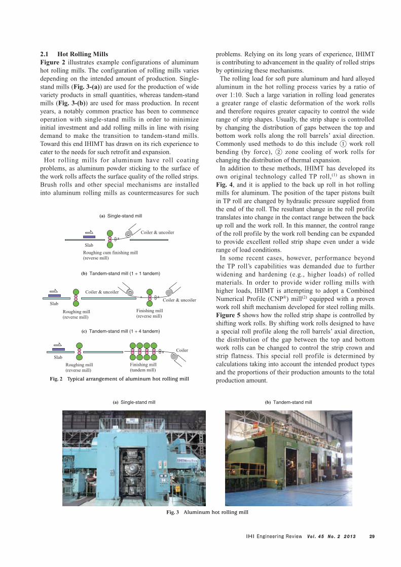
2.1 Hot Rolling MillsFigure 2 illustrates example configurations of aluminum hot rolling mills. The configuration of rolling mills varies depending on the intended amount of production. Single-stand mills (Fig. 3-(a)) are used for the production of wide variety products in small quantities, whereas tandem-stand mills (Fig. 3-(b)) are used for mass production. In recent years, a notably common practice has been to commence operation with single-stand mills in order to minimize initial investment and add rolling mills in line with rising demand to make the transition to tandem-stand mills. Toward this end IHIMT has drawn on its rich experience to cater to the needs for such retrofit and expansion.
Hot rolling mills for aluminum have roll coating problems, as aluminum powder sticking to the surface of the work rolls affects the surface quality of the rolled strips. Brush rolls and other special mechanisms are installed into aluminum rolling mills as countermeasures for such
problems. Relying on its long years of experience, IHIMT is contributing to advancement in the quality of rolled strips by optimizing these mechanisms.
The rolling load for soft pure aluminum and hard alloyed aluminum in the hot rolling process varies by a ratio of over 1:10. Such a large variation in rolling load generates a greater range of elastic deformation of the work rolls and therefore requires greater capacity to control the wide range of strip shapes. Usually, the strip shape is controlled by changing the distribution of gaps between the top and bottom work rolls along the roll barrels’ axial direction. Commonly used methods to do this include ① work roll bending (by force), ② zone cooling of work rolls for changing the distribution of thermal expansion.
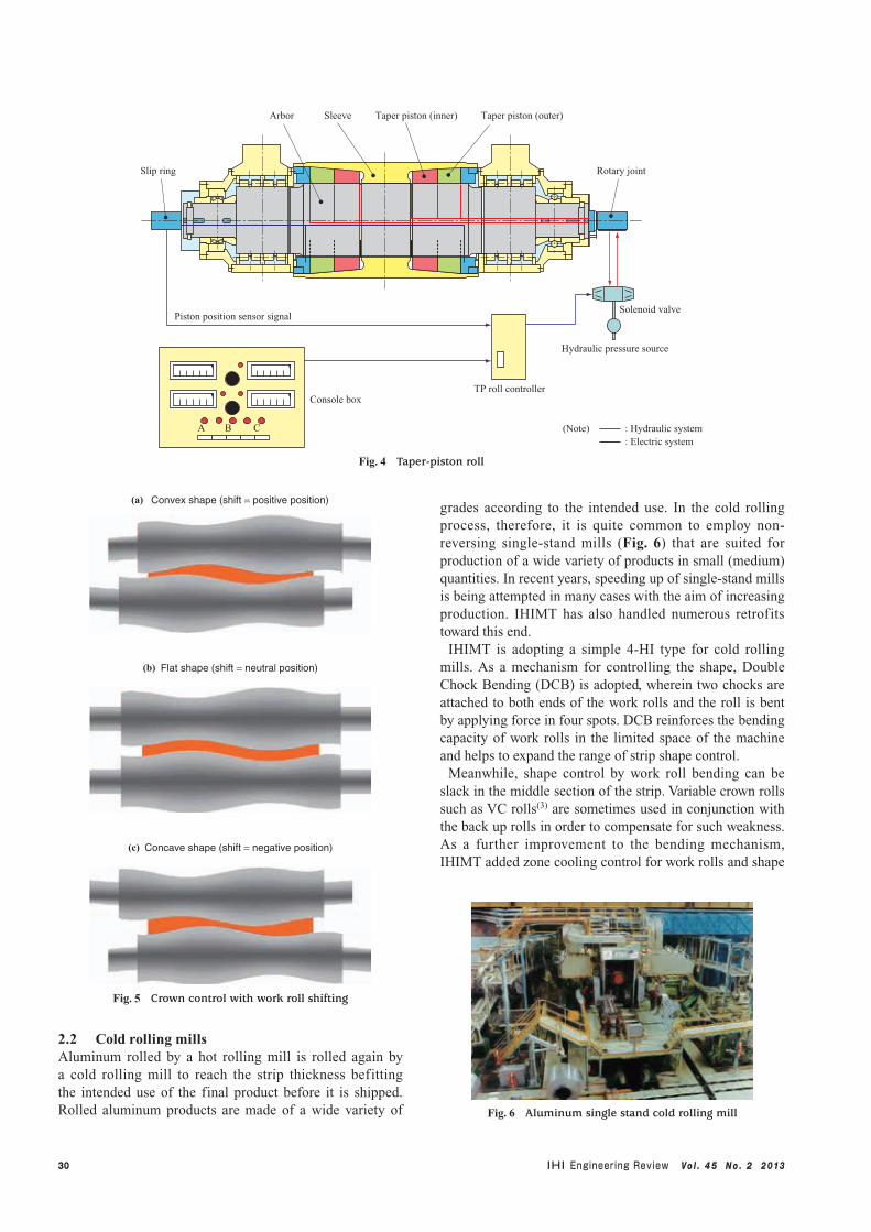
In addition to these methods, IHIMT has developed its own original technology called TP roll,(1) as shown in Fig. 4, and it is applied to the back up roll in hot rolling mills for aluminum. The position of the taper pistons built in TP roll are changed by hydraulic pressure supplied from the end of the roll. The resultant change in the roll profile translates into change in the contact range between the back up roll and the work roll. In this manner, the control range of the roll profile by the work roll bending can be expanded to provide excellent rolled strip shape even under a wide range of load conditions.
In some recent cases, however, performance beyond the TP roll’s capabilities was demanded due to further widening and hardening (e.g., higher loads) of rolled materials. In order to provide wider rolling mills with higher loads, IHIMT is attempting to adopt a Combined Numerical Profile (CNP®) mill(2) equipped with a proven work roll shift mechanism developed for steel rolling mills. Figure 5 shows how the rolled strip shape is controlled by shifting work rolls. By shifting work rolls designed to have a special roll profile along the roll barrels’ axial direction, the distribution of the gap between the top and bottom work rolls can be changed to control the strip crown and strip flatness. This special roll profile is determined by calculations taking into account the intended product types and the proportions of their production amounts to the total production amount.
Roughing cum finishing mill(reverse mill)
Roughing mill (reverse mill)
Finishing mill (reverse mill)
Roughing mill (reverse mill)
Finishing mill (tandem mill)
Coiler & uncoiler
Coiler & uncoiler
Coiler & uncoiler
Coiler
Slab
Slab
Slab
(a) Single-stand mill
(b) Tandem-stand mill (1 + 1 tandem)
(c) Tandem-stand mill (1 + 4 tandem)
Fig. 2 Typical arrangement of aluminum hot rolling mill
(a) Single-stand mill (b) Tandem-stand mill
Fig. 3 Aluminum hot rolling mill
30 Vo l . 4 5 N o . 2 2 013
2.2 Cold rolling millsAluminum rolled by a hot rolling mill is rolled again by a cold rolling mill to reach the strip thickness befitting the intended use of the final product before it is shipped. Rolled aluminum products are made of a wide variety of
grades according to the intended use. In the cold rolling process, therefore, it is quite common to employ non-reversing single-stand mills (Fig. 6) that are suited for production of a wide variety of products in small (medium) quantities. In recent years, speeding up of single-stand mills is being attempted in many cases with the aim of increasing production. IHIMT has also handled numerous retrofits toward this end.
IHIMT is adopting a simple 4-HI type for cold rolling mills. As a mechanism for controlling the shape, Double Chock Bending (DCB) is adopted, wherein two chocks are attached to both ends of the work rolls and the roll is bent by applying force in four spots. DCB reinforces the bending capacity of work rolls in the limited space of the machine and helps to expand the range of strip shape control.
Meanwhile, shape control by work roll bending can be slack in the middle section of the strip. Variable crown rolls such as VC rolls(3) are sometimes used in conjunction with the back up rolls in order to compensate for such weakness. As a further improvement to the bending mechanism, IHIMT added zone cooling control for work rolls and shape
Hydraulic pressure source
BA C
Console boxTP roll controller
Piston position sensor signal
Slip ring Rotary joint
Taper piston (outer)Taper piston (inner)SleeveArbor
Solenoid valve
(Note) : Hydraulic system : Electric system
Fig. 4 Taper-piston roll
(a) Convex shape (shift = positive position)
(b) Flat shape (shift = neutral position)
(c) Concave shape (shift = negative position)
Fig. 5 Crown control with work roll shifting
Fig. 6 Aluminum single stand cold rolling mill
31Vo l . 4 5 N o . 2 2 013
sensor rolls as described below to provide an automated, precise, and stable rolling system.2.3 Foil millsAluminum foils are traditionally used as packaging materials for food, etc. Demand has been surging recently as foils are finding increasing application as industrial materials such as battery materials. Foils with a thickness of 0.2 mm or less are made from a material called re-roll stock with a thickness of 0.30 to 0.65 mm that is fed from the cold rolling mill to undergo a repeated process of reduction by nearly 50% in each pass of the foil mill. Ultra-thin foils with a thickness of 0.01 mm or less are made by stacking two layers before rolling.
In general, non-reversing 4-HI mills are used as aluminum foil mills which comprise ① a roughing mill, ② an intermediate rolling mill, and ③ a finishing mill, according to the intended thickness and production amount (rolling time) of the foils. In some cases, in order to minimize initial investment, multi-function mills are used that can perform every process from roughing to finishing in one unit.
Quality control items of the foil rolling products include evenness in surface brightness and the absence of pin holes. In foil mills, measures to prevent quality loss with respect to these items are taken by minimizing the rotational resistance of the rolls that are directly in contact with the product, for example. In addition, extremely thin foil can even be ruptured by a piece of foil on the mill falling onto the rolled material. Building on such experience, meticulous considerations are made to provide a mechanism that makes it easier to clean the inside of the foil mill.
Foil shape control is cumbersome with regard to the method of directly controlling the gap between the rolls, since greater control is necessary in comparison to strip thickness. For this reason, a zone cooling control method is mainly adopted for correction of locally misshapen strips by changing the degree of thermal expansion of each work roll. In this method, a coolant with a different flow rate or temperature is sprayed on the work roll lengthwise along the location corresponding to the relevant shape defect. This induces a change in the amount of thermal expansion of the roll and thereby corrects the shape defect on the strip.
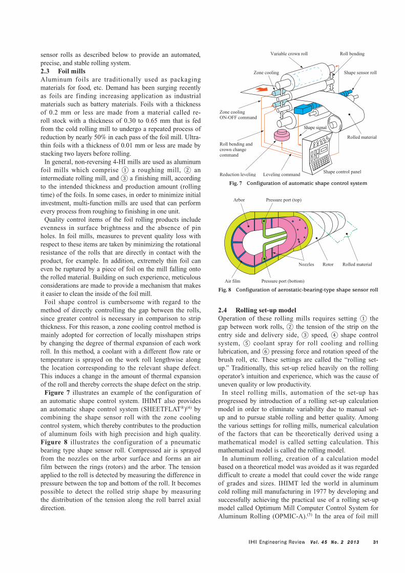
Figure 7 illustrates an example of the configuration of an automatic shape control system. IHIMT also provides an automatic shape control system (SHEETFLAT®)(4) by combining the shape sensor roll with the zone cooling control system, which thereby contributes to the production of aluminum foils with high precision and high quality. Figure 8 illustrates the configuration of a pneumatic bearing type shape sensor roll. Compressed air is sprayed from the nozzles on the arbor surface and forms an air film between the rings (rotors) and the arbor. The tension applied to the roll is detected by measuring the difference in pressure between the top and bottom of the roll. It becomes possible to detect the rolled strip shape by measuring the distribution of the tension along the roll barrel axial direction.
2.4 Rolling set-up modelOperation of these rolling mills requires setting ① the gap between work rolls, ② the tension of the strip on the entry side and delivery side, ③ speed, ④ shape control system, ⑤ coolant spray for roll cooling and rolling lubrication, and ⑥ pressing force and rotation speed of the brush roll, etc. These settings are called the “rolling set-up.” Traditionally, this set-up relied heavily on the rolling operator’s intuition and experience, which was the cause of uneven quality or low productivity.
In steel rolling mills, automation of the set-up has progressed by introduction of a rolling set-up calculation model in order to eliminate variability due to manual set-up and to pursue stable rolling and better quality. Among the various settings for rolling mills, numerical calculation of the factors that can be theoretically derived using a mathematical model is called setting calculation. This mathematical model is called the rolling model.
In aluminum rolling, creation of a calculation model based on a theoretical model was avoided as it was regarded difficult to create a model that could cover the wide range of grades and sizes. IHIMT led the world in aluminum cold rolling mill manufacturing in 1977 by developing and successfully achieving the practical use of a rolling set-up model called Optimum Mill Computer Control System for Aluminum Rolling (OPMIC-A).(5) In the area of foil mill
Arbor Pressure port (top)
Nozzles Rotor Rolled material
Air film Pressure port (bottom)
Fig. 8 Configuration of aerostatic-bearing-type shape sensor roll
Zone cooling ON-OFF command
Zone cooling
Variable crown roll Roll bending
Shape sensor roll
Reduction levelingShape control panel
Shape signal
Rolled material
Leveling command
Roll bending and crown change command
Fig. 7 Configuration of automatic shape control system
32 Vo l . 4 5 N o . 2 2 013
manufacturing, the company successfully put the rolling mill set-up system (Mill Master-F) into practical use for the first time in the world in 1995 by simulating the phenomena involved in foil rolling. Later, with respect to the tandem hot rolling mill, the company achieved automatic set-up of hot rolling by adding a temperature control model to the models to control the strip thickness and shape.
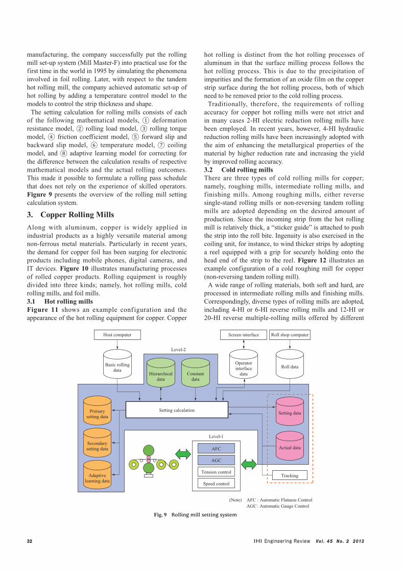
The setting calculation for rolling mills consists of each of the following mathematical models, ① deformation resistance model, ② rolling load model, ③ rolling torque model, ④ friction coefficient model, ⑤ forward slip and backward slip model, ⑥ temperature model, ⑦ coiling model, and ⑧ adaptive learning model for correcting for the difference between the calculation results of respective mathematical models and the actual rolling outcomes. This made it possible to formulate a rolling pass schedule that does not rely on the experience of skilled operators. Figure 9 presents the overview of the rolling mill setting calculation system.
3. Copper Rolling Mills
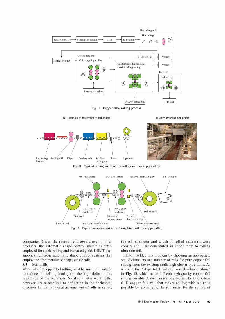
Along with aluminum, copper is widely applied in industrial products as a highly versatile material among non-ferrous metal materials. Particularly in recent years, the demand for copper foil has been surging for electronic products including mobile phones, digital cameras, and IT devices. Figure 10 illustrates manufacturing processes of rolled copper products. Rolling equipment is roughly divided into three kinds; namely, hot rolling mills, cold rolling mills, and foil mills.3.1 Hot rolling millsFigure 11 shows an example conf iguration and the appearance of the hot rolling equipment for copper. Copper
hot rolling is distinct from the hot rolling processes of aluminum in that the surface milling process follows the hot rolling process. This is due to the precipitation of impurities and the formation of an oxide film on the copper strip surface during the hot rolling process, both of which need to be removed prior to the cold rolling process.
Traditionally, therefore, the requirements of rolling accuracy for copper hot rolling mills were not strict and in many cases 2-HI electric reduction rolling mills have been employed. In recent years, however, 4-HI hydraulic reduction rolling mills have been increasingly adopted with the aim of enhancing the metallurgical properties of the material by higher reduction rate and increasing the yield by improved rolling accuracy.3.2 Cold rolling millsThere are three types of cold rolling mills for copper; namely, roughing mills, intermediate rolling mills, and f inishing mills. Among roughing mills, either reverse single-stand rolling mills or non-reversing tandem rolling mills are adopted depending on the desired amount of production. Since the incoming strip from the hot rolling mill is relatively thick, a “sticker guide” is attached to push the strip into the roll bite. Ingenuity is also exercised in the coiling unit, for instance, to wind thicker strips by adopting a reel equipped with a grip for securely holding onto the head end of the strip to the reel. Figure 12 illustrates an example configuration of a cold roughing mill for copper (non-reversing tandem rolling mill).
A wide range of rolling materials, both soft and hard, are processed in intermediate rolling mills and finishing mills. Correspondingly, diverse types of rolling mills are adopted, including 4-HI or 6-HI reverse rolling mills and 12-HI or 20-HI reverse multiple-rolling mills offered by different
(Note) AFC : Automatic Flatness Control AGC : Automatic Gauge Control
Primarysetting data
Secondarysetting data
Setting data
Adaptivelearning data
Basic rollingdata
Operatorinterface
data
Roll data
Hierarchicaldata
Constantdata
Host computer
Tracking
Screen interface
Setting calculation
AFC
AGC
Tension control
Speed control
Level-2
Level-1
Roll shop computer
Actual data
Fig. 9 Rolling mill setting system
33Vo l . 4 5 N o . 2 2 013
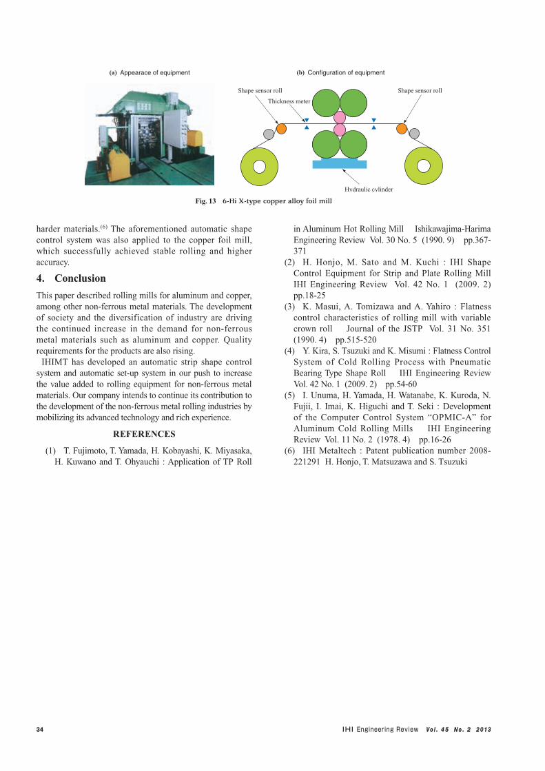
companies. Given the recent trend toward ever thinner products, the automatic shape control system is often employed for stable rolling and increased yield. IHIMT also supplies numerous automatic shape control systems that employ the aforementioned shape sensor rolls.3.3 Foil millsWork rolls for copper foil rolling must be small in diameter to reduce the rolling load given the high deformation resistance of the materials. Small-diameter work rolls, however, are susceptible to deflection in the horizontal direction. In the traditional arrangement of rolls in series,
the roll diameter and width of rolled materials were constrained. This constituted an impediment to rolling ultra-thin foil.
IHIMT tackled this problem by choosing an appropriate set of diameters and number of rolls for pure copper foil rolling from the existing multi-high cluster type mills. As a result, the X-type 6-HI foil mill was developed, shown in Fig. 13, which made difficult high-quality copper foil rolling possible. A mechanism was devised for this X-type 6-HI copper foil mill that makes rolling with ten rolls possible by exchanging the roll units, for the rolling of
Re-heating furnace
Rolling mill Cooling unit Shear Up coilerSurface milling unit
Edger
(a) Example of equipment configuration (b) Appearance of equipment
Fig. 11 Typical arrangement of hot rolling mill for copper alloy
Pay-off reel
Pinch roll
No. 1 entry bridle roll
Inter-stand tension meter
Inter-stand thickness meter
Delivery thickness meter
No. 2 entry bridle roll
Delivery tension meter
Deflector roll
No. 1 roll stand No. 2 roll stand Tension reel (with grip) Belt wrapper
Fig. 12 Typical arrangement of cold roughing mill for copper alloy
Raw materials Melting and casting Slab Re-heating
Surface milling
Foil rolling
Foil mill
Annealing Product
Product
Process annealing
Cold roughing rolling
Cold rolling mill
Hot rolling
Hot rolling mill
Cold intermediate rollingCold finishing rolling
Product
Process annealing
Fig. 10 Copper alloy rolling process
34 Vo l . 4 5 N o . 2 2 013
harder materials.(6) The aforementioned automatic shape control system was also applied to the copper foil mill, which successfully achieved stable rolling and higher accuracy.
4. Conclusion
This paper described rolling mills for aluminum and copper, among other non-ferrous metal materials. The development of society and the diversification of industry are driving the continued increase in the demand for non-ferrous metal materials such as aluminum and copper. Quality requirements for the products are also rising.
IHIMT has developed an automatic strip shape control system and automatic set-up system in our push to increase the value added to rolling equipment for non-ferrous metal materials. Our company intends to continue its contribution to the development of the non-ferrous metal rolling industries by mobilizing its advanced technology and rich experience.
REFERENCES
(1) T. Fujimoto, T. Yamada, H. Kobayashi, K. Miyasaka, H. Kuwano and T. Ohyauchi : Application of TP Roll
in Aluminum Hot Rolling Mill Ishikawajima-Harima Engineering Review Vol. 30 No. 5 (1990. 9) pp.367-371
(2) H. Honjo, M. Sato and M. Kuchi : IHI Shape Control Equipment for Strip and Plate Rolling Mill IHI Engineering Review Vol. 42 No. 1 (2009. 2) pp.18-25
(3) K. Masui, A. Tomizawa and A. Yahiro : Flatness control characteristics of rolling mill with variable crown roll Journal of the JSTP Vol. 31 No. 351 (1990. 4) pp.515-520
(4) Y. Kira, S. Tsuzuki and K. Misumi : Flatness Control System of Cold Rolling Process with Pneumatic Bearing Type Shape Roll IHI Engineering Review Vol. 42 No. 1 (2009. 2) pp.54-60
(5) I. Unuma, H. Yamada, H. Watanabe, K. Kuroda, N. Fujii, I. Imai, K. Higuchi and T. Seki : Development of the Computer Control System “OPMIC-A” for Aluminum Cold Rolling Mills IHI Engineering Review Vol. 11 No. 2 (1978. 4) pp.16-26
(6) IHI Metaltech : Patent publication number 2008-221291 H. Honjo, T. Matsuzawa and S. Tsuzuki
Shape sensor roll
Thickness meter
Hydraulic cylinder
Shape sensor roll
(a) Appearace of equipment (b) Configuration of equipment
Fig. 13 6-Hi X-type copper alloy foil mill