Character Animation with Direct3D Vertex Shaders -...
15
Character Animation with Direct3D Vertex Shaders Character Animation with Direct3D Vertex Shaders David Gosselin ATI Research Introduction With the introduction of vertex shaders to modern graphics hardware, we are able to move a large portion of the character animation processing from the CPU to the graphics hardware. Two common character animation techniques are tweening (also known as morphing) and skinning (also called skeletal animation). This chapter describes how both of these techniques and some related variations can be performed using vertex shaders. We will also talk about how to combine animation with the per- pixel lighting techniques described in the introductory chapter [Engel]. We will conclude with a discussion of some geometry decompression techniques, which allow an application to minimize memory usage and memory bandwidth. Tweening Tweening is the technique of linearly interpolating between two (or more) “key” frames of animation. This technique is used in many popular games like Quake. The artwork consists of a character or object in a few poses spaced relatively close together in time. For example, the figure below shows a few frames of an animation stored as key frames. Figure 1 – An object animated with tweening In order to perform this type of animation, the object’s position and normal data are stored for each frame of the animation. At runtime, two frames are selected which represent the current state the animation. The vertex buffers containing these two frames Excerpted from ShaderX: Vertex and Pixel Shader Tips and Tricks 1
Transcript of Character Animation with Direct3D Vertex Shaders -...

Character Animation with Direct3D Vertex Shaders
Character Animation with Direct3D Vertex Shaders
David Gosselin ATI Research
Introduction
With the introduction of vertex shaders to modern graphics hardware, we are able to move a large portion of the character animation processing from the CPU to the graphics hardware. Two common character animation techniques are tweening (also known as morphing) and skinning (also called skeletal animation). This chapter describes how both of these techniques and some related variations can be performed using vertex shaders. We will also talk about how to combine animation with the per-pixel lighting techniques described in the introductory chapter [Engel]. We will conclude with a discussion of some geometry decompression techniques, which allow an application to minimize memory usage and memory bandwidth. Tweening
Tweening is the technique of linearly interpolating between two (or more) “key” frames of animation. This technique is used in many popular games like Quake. The artwork consists of a character or object in a few poses spaced relatively close together in time. For example, the figure below shows a few frames of an animation stored as key frames.
Figure 1 – An object animated with tweening
In order to perform this type of animation, the object’s position and normal data are stored for each frame of the animation. At runtime, two frames are selected which represent the current state the animation. The vertex buffers containing these two frames
Excerpted from ShaderX: Vertex and Pixel Shader Tips and Tricks
1

Character Animation with Direct3D Vertex Shaders
are loaded as separate streams of data. Typically setting up the vertex streams looks something like: d3dDevice->SetStreamSource (0, frame0VertexBuffer, frame0Stride); d3dDevice->SetStreamSource (1, frame1VertexBuffer, frame1Stride);
Additionally, a tween factor is computed at run time. The tween factor represents the animation time between the two frames, with the value 0.0 corresponding to the first frame and the value 1.0 corresponding to the second frame. This value is used to perform the linear interpolation of the position data. One way to compute this value is shown below: float t = time; if (t < 0) { t = (float)fmod ((float)(-t), TotalAnimationTime); t = TotalAnimationTime - t; } float tween = (float)fmod ((float64)t, TotalAnimationTime); tween /= TotalAnimationTime; tween *= (NumberOfAnimationFrames - 1); which = (int32)floor ((float64)tween); tween -= which;
The tween value and any lighting constants you may be using are loaded into the constant store. The vertex shader code then only needs to implement the following equation in order to perform the interpolation between the two frames.
A*(1-tween) + B*tween
Generally, the vertex shader should also multiply by the concatenated world, view, and projection matrix. The following vertex shader shows an implementation of tweening: ; position frame 0 in v0 ; position frame 1 in v14 ; tween in c0.x ; World/View/Projection matrix in c12-c15 ; Figure out 1-tween constant ; use the 1.0 from position’s w sub r0, v0.wwww, c0 ; Compute the tweened position mul r1, v0, r0.xxxx mad r1, v14, c0.xxxx, r1 ; Multiply by the view/projection and pass it along m4x4 oPos, r1, c12
Excerpted from ShaderX: Vertex and Pixel Shader Tips and Tricks
2

Character Animation with Direct3D Vertex Shaders
To save some vertex shader instructions, the value of (1 – tweenfactor) can be
computed by the application. Both of these values can be loaded into the constant store, in this case as part of the same constant vector. The z and w components of this constant register are also good places to stick handy constants like 1.0, 0.0, 2.0, 0.5, etc. if you happen to need them. The resulting vertex shader code looks like the following: ; position frame 0 in v0 ; normal frame 0 in v3 ; position frame 1 in v14 ; normal frame 1 in v15 ; tween in c0.x ; 1 – tween in c0.y ; View/Projection matrix in c12-c15 ; Compute the tweened position mul r1, v0, c0.yyyy mad r1, v14, c0.xxxx, r1 ; Multiply by the view/projection and pass it along m4x4 oPos, r1, c12 In this section, we have explored an efficient tweening algorithm that can be easily computed within a vertex shader. It has the advantages of being very quick to compute and working well with higher order surface tessellation schemes such as N-Patches. Unfortunately, tweening has the downside of requiring quite a bit of data to be stored in memory for each animation. Another popular technique, which addresses the memory usage issue is skinning. Skinning requires more vertex shader instructions but less data per frame of animation. We will explore skinning in more detail in the following section. Skinning
Skinning is the process of blending the contributions from several matrices in order to find the final vertex position. Typically the character modeling tool describes the matrices using a series of “bones.” Figure 3 below shows what this looks like in 3D Studio MAX.
Excerpted from ShaderX: Vertex and Pixel Shader Tips and Tricks
3

Character Animation with Direct3D Vertex Shaders
Figure 2 – Skeleton of a skinned character with overlayed polygon mesh
The diamond shapes in Figure 3 represent the various control matrices. The inner
triangles represent the “bones.” In this tool, the artists can move the joints and the model’s position is updated using inverse kinematics. During export of this data from MAX, the triangles are grouped according to which matrices affect their position. Further preprocessing generates the vertex buffers used by the Direct3D API. The vertices created from the mesh have bone weights, which represent the amount of influence from the corresponding matrices (bones). These weights are used to blend the contributions of the corresponding matrices according to the following equation:
Final Position = SUM (matrix[n]*position*weight[n])
Before the advent of vertex shading hardware, these computations took place on the CPU (typically referred to as Software Skinning). This approach has the benefit of being able to compute accurate normals after skinning a model but typically it is fairly costly in terms of the amount of computation required. Some earlier graphics hardware had a fixed-function hardware dedicated to performing these computations. The user specified a Flexible Vertex Format (FVF), which contained the skinning weights and loaded two to four numbered world matrices to be blended. With vertex shaders programmers have the ability to tailor the type of skinning to their own applications. In this section, we will explore two different kinds of skinning: a four matrix skinned approach, which mirrors the functionality available from the fixed function pipeline, and a paletted approach, which allows for greater batching of drawing calls.
The following vertex shader shows how to perform four matrix skinning. One common technique to reduce the amount of per-vertex data is to only store three vertex weights and compute a fourth one in the vertex shader by assuming that the weights sum to 1.0. At run time, the matrices for a particular group are loaded into the constant store and the appropriate vertex buffers are loaded. The vertex shader code looks like the following:
Excerpted from ShaderX: Vertex and Pixel Shader Tips and Tricks
4

Character Animation with Direct3D Vertex Shaders
; position in v0 ; matrix weights in v1 ; c0.z = 1.0 ; View/Projection matrix in c12-c15 ; World 0 matrix in c16-c19 ; World 1 matrix in c20-c23 ; World 2 matrix in c24-c27 ; World 3 matrix in c28-31 ; Multiply input position by matrix 0 m4x4 r0, v0, c16 mul r1, r0, v1.xxxx ; Multiply input position by matrix 1 and sum m4x4 r0, v0, c20 mad r1, r0, v1.yyyy, r1 ; Multiply input position by matrix 2 and sum m4x4 r0, v0, c24 mad r1, r0, v1.zzzz, r1 ; Multiply input position by matrix 3 m4x4 r0, v0, c28 ; Compute fourth weight dp3 r10, v1, c0.zzzz sub r11, c0.zzzz, r10 ; sum mad r1, r0, r11.wwww, r1 ; Multiply by the view/projection matrix m4x4 oPos, r1, c20
One variation on this technique is to store a palette of matrices in the constant store. During preprocessing, four indices are stored per-vertex. These indices determine which matrices from the palette are used in the blending process. Using this technique, a much larger set of triangles can be processed without changing constant store state (typically an expensive operation). Note that it is still worthwhile to sort the triangles by similar bone matrices to take advantage of pipelined hardware. The vertex shader code takes advantage of the indexing register in order to reach into the constant store to retrieve the correct matrices. The following vertex shader shows one way of implementing this technique. ; position in v0 ; matrix weights in v1 ; matrix indices in v2 ; c0.z = 1.0 ; c10 = (16.0, 4.0, 1.0, 0.0) ; View/Projection matrix in c12-c15
Excerpted from ShaderX: Vertex and Pixel Shader Tips and Tricks
5

Character Animation with Direct3D Vertex Shaders
; World 0 matrix in c16-c19 ; World 1 matrix in c20-c23 ; . . . Other world matrices follow ; figure out the last weight dp3 r5, v1, c0.zzzz sub r5.w, c0.zzzz, r5 ; First world matrix constant = index*4 + start index mad r7, v2.xyzw, c10.y, c10.x ; Skin by Matrix 0 mov a0.x, r7.x m4x4 r0, v0, c[a0.x] mul r1, r0, v1.xxxx ; Skin by Matrix 1 and sum mov a0.x, r7.y m4x4 r0, v0, c[a0.x] mad r1, r0, v1.yyyy, r1 ; Skin by Matrix 2 and sum mov a0.x, r7.z m4x4 r0, v0, c[a0.x] mad r1, r0, v1.zzzz, r1 ; Skin by Matrix 3 and sum mov a0.x, r7.w m4x4 r0, v0, c[a0.x] mad r1, r0, r5.wwww, r1 ; Multiply by the view/projection and pass it along m4x4 oPos, r1, c12
One drawback to using the paletted skinning approach is that it doesn’t work well with higher order surfaces. The issue stems from the fact that vertex shaders are computed post-tessellation and any vertex data other than positions and normals are linearly interpolated. Interpolating the index values for blend matrices is nonsensical. Skinning and Tweening Together
It is also possible to blend skinning and tweening. There are cases where it makes sense to model a portion of a character using tweening but you still want some basic movement controlled by bones. For example you might want the face of a character to be tweened in order to capture some subtle movements that would require a large number of bones and would be difficult to manage within an art tool, but you want to use bones for the movement of the head and body. The following figures show this kind of example where the mouth and claws of the character are tweened and skinned.
Excerpted from ShaderX: Vertex and Pixel Shader Tips and Tricks
6

Character Animation with Direct3D Vertex Shaders
The figure below shows a few frames of animation using skinning alone.
The next figure shows just the tweened portion of the animation. Note the complex animation of the mouth and claws.
The final figure shows the skinning and tweening animations being performed simultaneously on the character.
When performing this type of animation the tween portion is computed first and the then the resultant position is skinned. The following vertex shader shows one implementation of this technique. ; position frame 0 in v0 ; position frame 1 in v14 ; matrix weights in v1 ; matrix indices in v2 ; c0.z = 1.0 ; tween in c9.x ; c10 = (16.0, 4.0, 1.0, 0.0) ; View/Projection matrix in c12-c15
Excerpted from ShaderX: Vertex and Pixel Shader Tips and Tricks
7

Character Animation with Direct3D Vertex Shaders
; World 0 matrix in c16-c19 ; World 1 matrix in c20-c23 ; . . . Other world matrices follow ; Figure out tween constant sub r9, v0.wwww, c9 mov r9.y, c9.x ; Compute the tweened position mul r10, v0, r9.xxxx mad r2, v14, r9.yyyy, r10 ; figure out the last weight mov r5, v1 dp3 r3, v1, c0.zzzz sub r5.w, c0.zzzz, r3 ; First world matrix constant = index*4 + start index mad r7, v2.xyzw, c10.y, c10.x ; Skin by Matrix 0 mov a0.x, r7.x m4x4 r0, r2, c[a0.x] mul r1, r0, v1.xxxx ; Skin by Matrix 1 and sum mov a0.x, r7.y m4x4 r0, r2, c[a0.x] mad r1, r0, v1.yyyy, r1 ; Skin by Matrix 2 and sum mov a0.x, r7.z m4x4 r0, r2, c[a0.x] mad r1, r0, v1.zzzz, r1 ; Skin by Matrix 3 and sum mov a0.x, r7.w m4x4 r0, r2, c[a0.x] mad r1, r0, r5.wwww, r1 ; Multiply by the projection and pass it along m4x4 oPos, r1, c12
In this section we explored one way to combine two different types of character animation. It is obviously just one way to mix the two types of animation. One benefit of vertex shaders is the ability to customize the vertex processing to get different effects that fit the needs of your particular application. Hopefully, this will provide you with some ideas for how to customize animation to suit your own needs.
So far, we have only discussed animation of vertex positions and normals. This is
sufficient for vertex lighting of animated characters. Modern graphics chips provide very Excerpted from ShaderX: Vertex and Pixel Shader Tips and Tricks
8

Character Animation with Direct3D Vertex Shaders
powerful pixel shading capabilities that allow lighting to be performed per-pixel. To do this, however, some care must be taken in the vertex shader to properly set up the per-pixel lighting computations. This will be discussed in the next section.
Animating Tangent Space for Per-Pixel Lighting
In order to reasonably light a character animated by these techniques it is important to animate the normal as well as just the position. In the case of tweening this means storing a normal along with the position and interpolating the normal in the same way as the position. Getting the “right” normal isn’t quite as simple in the case of skinning. Since skinning can potentially move each vertex in very different ways they only way to get completely correct normals is to recompute the normal at each vertex once the mesh is reskinned. Typically this tends to be a very expensive operation and would require a lot of additional information stored per-vertex. To top it off, there really isn’t a way to index other vertices from within a vertex shader. The typical compromise, which gives “good enough” results, is to just skin the normal using just the rotation part of the bone matrices.
Additionally, if you are doing per-pixel bump mapping or other effects requiring texture/tangent space discussed in the introductory chapter by [Engel], you also need to skin the basis vectors. The following shader shows the paletted matrix skinned version that also skins the tangent/texture space basis vectors. ; position in v0 ; matrix weights in v1 ; matrix indices in v2 ; normal in v3 ; tangent in v9 ; binormal in v10 ; c0.z = 1.0 ; c10 = (16.0, 4.0, 1.0, 0.0) ; View/Projection matrix in c12-c15 ; World 0 matrix in c16-c19 ; World 1 matrix in c20-c23 ; . . . Other world matrices follow ; figure out the last weight dp3 r3, v1, c0.zzzz sub r5.w, c0.zzzz, r3 ; First world matrix constant = index*4 + start index mad r7, v2.xyzw, c10.y, c10.x ; Skin by Matrix 0 mov a0.x, r7.x m4x4 r0, v0, c[a0.x] ; Position mul r1, r0, v1.xxxx
Excerpted from ShaderX: Vertex and Pixel Shader Tips and Tricks
9

Character Animation with Direct3D Vertex Shaders
m3x3 r0, v9, c[a0.x] ; Tangent mul r2, r0, v1.xxxx m3x3 r0, v10, c[a0.x] ; Bi-Normal mul r3, r0, v1.xxxx m3x3 r0, v3, c[a0.x] ; Normal mul r4, r0, v1.xxxx ; Skin by Matrix 1 and sum mov a0.x, r7.y m4x4 r0, v0, c[a0.x] ; Position mad r1, r0, v1.yyyy, r1 m3x3 r0, v9, c[a0.x] ; Tangent mad r2, r0, v1.yyyy, r2 m3x3 r0, v10, c[a0.x] ; Bi-Normal mad r3, r0, v1.yyyy, r3 m3x3 r0, v3, c[a0.x] ; Normal mad r4, r0, v1.yyyy, r4 ; Skin by Matrix 2 and sum mov a0.x, r7.z m4x4 r0, v0, c[a0.x] ; Position mad r1, r0, v1.zzzz, r1 m3x3 r0, v9, c[a0.x] ; Tangent mad r2, r0, v1.zzzz, r2 m3x3 r0, v10, c[a0.x] ; Bi-Normal mad r3, r0, v1.zzzz, r3 m3x3 r0, v3, c[a0.x] ; Normal mad r4, r0, v1.zzzz, r4 ; Skin by Matrix 3 and sum mov a0.x, r7.w m4x4 r0, v0, c[a0.x] ; Position mad r1, r0, r5.wwww, r1 m3x3 r0, v9, c[a0.x] ; Tangent mad r2, r0, r5.wwww, r2 m3x3 r0, v10, c[a0.x] ; Bi-Normal mad r3, r0, r5.wwww, r3 m3x3 r0, v3, c[a0.x] ; Normal mad r4, r0, r5.wwww, r4 ; Multiply by the projection and pass it along m4x4 oPos, r1, c12 ; >>>> At this point: ; >>>>> r1 contains the skinned vertex position ; >>>>> r2 contains the tangent (v9) ; >>>>> r3 contains the binormal (v10) ; >>>>> r4 contains the normal (v3)
Now what can we do with this basis vector you might ask. Well one common usage is to perform per-pixel “Dot3” bump mapping. In order to compute this two
Excerpted from ShaderX: Vertex and Pixel Shader Tips and Tricks
10

Character Animation with Direct3D Vertex Shaders
textures are needed. The first texture is the base map, which contains the color on the surface. The second texture is the bump map that contains the normal at each point in the original texture encoded into the red, green, and blue channels. Within the vertex shader the vector from the light to the vertex is computed, normalized, and converted into tangent/texture space. This vector is then interpolated per-pixel before being sent to the pixel shader. Per-Pixel Lighting
Additionally within the vertex shader you can compute a light falloff. This involves sending data about the light falloff values in the constant store. The three values sent to the vertex shader are the distance from the light when the falloff starts, the distance from the light where the falloff ends, and the difference between those two values. The following shader code builds upon the previous shader and performs the calculations for three bumped diffuse lights. If fewer lights are desired the same shader can be used by setting the color of one or more of the lights to black (0,0,0,0). ; c0.z = 1.0 ; c1 has the position of light 1 ; c2 has the color of light 1 ; c3.x has the start of the falloff for light 1 ; c3.y has the end of the falloff for light 1 ; c3.z has the difference between the end of the falloff and the ; start of the falloff ; c4 has the position of light 2 ; c5 has the color of light 2 ; c6.x has the start of the falloff for light 2 ; c6.y has the end of the falloff for light 2 ; c6.z has the difference between the end of the falloff and the ; start of the falloff ; c7 has the position of light 2 ; c8 has the color of light 2 ; c9.x has the start of the falloff for light 2 ; c9.y has the end of the falloff for light 2 ; c9.z has the difference between the end of the falloff and the ; start of the falloff ;;;;;;;;;;;;;;;;;;;;;;;;;;;;;;;;;;;;;;;;;;;;;;;;;;;;;;;;;;;;;;;; ; Compute vector for light 1 sub r0, c1, r1 ; Ray from light to point dp3 r5.x, r0, r0 ; length^2 rsq r5.y, r5.x ; 1/length mul r0, r0, r5.y ; normalized rcp r5.z, r5.y ; length m3x3 r8, r0, r2 ; Convert to tangent space dp3 r9.x, r8, r8 ; length^2 rsq r9.y, r9.x ; 1/length mul oT2.xyz, r8, r9.y ; normalized
Excerpted from ShaderX: Vertex and Pixel Shader Tips and Tricks
11

Character Animation with Direct3D Vertex Shaders
sub r7.x, c3.y, r5.z ; fallEnd - length mul r7.y, c3.z, r7.x ; (fallEnd - length)/ ; (fallEnd-fallStart) min r7.w, r7.y, c0.z ; clamp mul oD0.xyz, r7.w, c2 ; falloff * light color ;;;;;;;;;;;;;;;;;;;;;;;;;;;;;;;;;;;;;;;;;;;;;;;;;;;;;;;;;;;;;;;; ; Compute vector for light 2 sub r0, c4, r1 ; Ray from light to the point dp3 r5.x, r0, r0 ; length^2 rsq r5.y, r5.x ; 1/length mul r0, r0, r5.y ; normalized rcp r5.z, r5.y ; length m3x3 r8, r0, r2 ; Convert to tangent space dp3 r9.x, r8, r8 ; length^2 rsq r9.y, r9.x ; 1/length mul oT3.xyz, r8, r9.y ; normalized sub r7.x, c6.y, r5.z ; fallEnd - length mul r7.y, c6.z, r7.x ; (fallEnd - length)/ ; (fallEnd - fallStart) min r7.w, r7.y, c0.z ; clamp mul oD1.xyz, r7.w, c5 ; falloff * light color ;;;;;;;;;;;;;;;;;;;;;;;;;;;;;;;;;;;;;;;;;;;;;;;;;;;;;;;;;;;;;;;; ; Compute vector for light 3 sub r0, c7, r1 ; Ray from light to the point dp3 r5.x, r0, r0 ; length^2 rsq r5.y, r5.x ; 1/length mul r0, r0, r5.y ; normalized rcp r5.z, r5.y ; length m3x3 r8, r0, r2 ; Convert to tangent space dp3 r9.x, r8, r8 ; length^2 rsq r9.y, r9.x ; 1/length mul oT4.xyz, r8, r9.y ; normalized sub r7.x, c9.y, r5.z ; fallEnd - length mul r7.y, c9.z, r7.x ; (fallEnd - length)/ ; (fallEnd- fallStart) min r7.w, r7.y, c0.z ; clamp mul oT5.xyz, r7.w, c8 ; falloff * light color ;;;;;;;;;;;;;;;;;;;;;;;;;;;;;;;;;;;;;;;;;;;;;;;;;;;;;;;;;;;;;;;; ; Pass along the texture coordinates. mov oT0.xy, v7.xy mov oT1.xy, v8.xy
In the pixel shader, we compute the dot products and sum up the contributions from all three lights. In addition, the light colors passed into the above shaders are pre-
Excerpted from ShaderX: Vertex and Pixel Shader Tips and Tricks
12

Character Animation with Direct3D Vertex Shaders
divided by two to allow a bigger range of light colors and to allow the lights to over-brighten the base textures. Within the pixel shader, this range is re-expanded by using the _x2 modifier on the colors. ps.1.4 ; c2 – contains the ambient lighting color texld r0, t0 ; DOT3 Bump Map Texture texld r1, t1 ; Base Texture texcrd r2.rgb, t2 ; L1 – light 1 vector texcrd r3.rgb, t3 ; L2 – light 2 vector texcrd r4.rgb, t4 ; L3 – light 3 vector ; v0 – C1 color of light 1 (from above) ; v1 – C1 color of light 2 (from above) texcrd r5.rgb, t5 ; C3 – color of light 3 dp3_sat r2, r0_bx2, r2_bx2 ; N.L1 mul r2, r2, v0_x2 ; (N.L1)*C1 dp3_sat r3, r0_bx2, r3_bx2 ; N.L2 mad r2, r3, v1_x2, r2 ; ((N.L1)*C1) + ((N.L2)*C2) dp3_sat r4, r0_bx2, r4_bx2 ; N.L2 mad r2.rgb, r4, r5_x2, r2 ; ((N.L1)*C1) + ((N.L2)*C2) + ; ((N.L3)*C3) add r2.rgb, r2, c2 ; add ambient mul r0.rgb, r2, r1 ; ((N.L1)*C1) + ((N.L2)*C2) + ; ((N.L3)*C3)*base
The following figures show various pieces of this shader in action. The first three show the contributions from each of the individual lights. The fourth shows the summation of all the lighting contributions and the fifth shows the base texture for the character.
The next figure shows a few frames of animation with the full shader in action.
Excerpted from ShaderX: Vertex and Pixel Shader Tips and Tricks
13
Character Animation with Direct3D Vertex Shaders
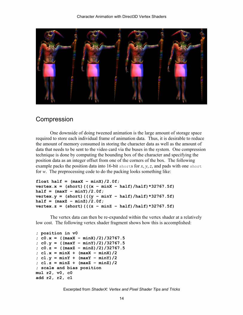
Compression
One downside of doing tweened animation is the large amount of storage space required to store each individual frame of animation data. Thus, it is desirable to reduce the amount of memory consumed in storing the character data as well as the amount of data that needs to be sent to the video card via the buses in the system. One compression technique is done by computing the bounding box of the character and specifying the position data as an integer offset from one of the corners of the box. The following example packs the position data into 16-bit shorts for x, y, z, and pads with one short for w. The preprocessing code to do the packing looks something like: float half = (maxX – minX)/2.0f; vertex.x = (short)(((x – minX – half)/half)*32767.5f) half = (maxY – minY)/2.0f; vertex.y = (short)(((y – minY – half)/half)*32767.5f) half = (maxZ – minZ)/2.0f; vertex.z = (short)(((z – minZ – half)/half)*32767.5f)
The vertex data can then be re-expanded within the vertex shader at a relatively low cost. The following vertex shader fragment shows how this is accomplished: ; position in v0 ; c0.x = ((maxX – minX)/2)/32767.5 ; c0.y = ((maxY – minY)/2)/32767.5 ; c0.z = ((maxZ – minZ)/2)/32767.5 ; c1.x = minX + (maxX – minX)/2 ; c1.y = minY + (maxY – minY)/2 ; c1.z = minZ + (maxZ – minZ)/2 ; scale and bias position mul r2, v0, c0 add r2, r2, c1
Excerpted from ShaderX: Vertex and Pixel Shader Tips and Tricks
14

Character Animation with Direct3D Vertex Shaders
Excerpted from ShaderX: Vertex and Pixel Shader Tips and Tricks
15
A similar technique can be applied to the weights for the skinning matrices. Again, a small bit of preprocessing code: vertex.w1 = (unsigned char)((float)(w1)/255.0f); vertex.w2 = (unsigned char)((float)(w2)/255.0f); vertex.w3 = (unsigned char)((float)(w3)/255.0f);
A few vertex shader instructions can expand this data back into floating point data for use to compute the skinned position. ; v1 contains the weights ; c0.x = 0.003921569 = 1/255 ; c0.z = 1.0 ; unpack the weights mul r9, v1, c0.x dp3 r9.w, r9, c0.zzzz sub r9.w, c0.zzzz, r9.w
Normal data can also be compressed by sacrificing some quality by quantizing the normals into bytes or shorts and doing a similar unpacking process within the vertex shader. The following code shows how the data is packed within a preprocessing tool: vertex.nx = (unsigned char)(nx*127.5 + 127.5); vertex.ny = (unsigned char)(ny*127.5 + 127.5); vertex.nz = (unsigned char)(nz*127.5 + 127.5);
A small bit of vertex shader code can be used to decompress the normals: ; v3 contains the normal ; c0.x = 0.007843137 = 1/127.5 ; r2.w = 1.0 mad r3, v3, c0.x, -r2.w ; scale and bias normal to -1 to 1 range
In this section, we showed a few ways to compress various vertex components. These techniques can be used to significantly reduce the amount of data required per character. They should however be used with some caution since they are lossy methods of compression and will not work with all data sets. For more on vertex compression see the “Vertex Decompression in a Shader” by [Calver]. Summary
This chapter has shown a few ways to perform character animation within a vertex shader. This should be considered a starting point for your exploration of character animation through vertex shaders. Vertex shaders give you the power to customize the graphics pipeline for your application, allowing you to free up the CPU for making a more engaging game.