CHAPTERS A APPROACH STANDARDS VENTION AND …
26
REGISTRO BRASILEIRO Rules for the Construction and Classification of Ships OILTANKERS - Title 32 DE NAVIOS E AERONAVES Identified by their Mission – Part II HULL EQUIPMENT - Section 3 RGMM20EN CHAPTER - Index PART II RULES FOR THE CONSTRUCTION AND CLASSIFICATION OF SHIPS IDENTIFIED BY THEIR MISSION TITLE 32 OIL TANKERS SECTION 3 HULL EQUIPMENT CHAPTERS A APPROACH B DOCUMENTS, REGULATIONS AND STANDARDS See Part II, Title 11, Section 3 C MATERIALS AND MANLABOUR See Part II, Title 11, Section 3 D SPECIFIC SYSTEM REQUIREMENTS E FIRE DETECTION, PROTECTION, PRE- VENTION AND FIGHTING F FIRE DETECTION, PROTECTION, PRE- VENTION AND FIGHTING VESSELS HAV- ING GT < 500 G SHIP MANEUVERING: RUDDERS, SOLE PIECES AND RUDDER HORNS See Part II, Title 11, Section 3 T TESTS AND INSPECTIONS See Part II, Title 11, Section 3
Transcript of CHAPTERS A APPROACH STANDARDS VENTION AND …

REGISTRO BRASILEIRO Rules for the Construction and Classification of Ships OIL TANKERS - Title 32
DE NAVIOS E AERONAVES Identified by their Mission – Part II HULL EQUIPMENT - Section 3
RGMM20EN CHAPTER - Index
PART II RULES FOR THE CONSTRUCTION
AND CLASSIFICATION OF SHIPS
IDENTIFIED BY THEIR MISSION
TITLE 32 OIL TANKERS
SECTION 3 HULL EQUIPMENT
CHAPTERS
A APPROACH
B DOCUMENTS, REGULATIONS AND
STANDARDS
See Part II, Title 11, Section 3
C MATERIALS AND MANLABOUR
See Part II, Title 11, Section 3
D SPECIFIC SYSTEM REQUIREMENTS
E FIRE DETECTION, PROTECTION, PRE-
VENTION AND FIGHTING
F FIRE DETECTION, PROTECTION, PRE-
VENTION AND FIGHTING VESSELS HAV-
ING GT < 500
G SHIP MANEUVERING: RUDDERS, SOLE
PIECES AND RUDDER HORNS
See Part II, Title 11, Section 3
T TESTS AND INSPECTIONS
See Part II, Title 11, Section 3


REGISTRO BRASILEIRO Rules for the Construction and Classification of Ships OIL TANKERS - Title 32
DE NAVIOS E AERONAVES Identified by their Mission – Part II HULL EQUIPMENT - Section 3
RGMM20EN CHAPTER - Index


REGISTRO BRASILEIRO Rules for the Construction and Classification of Ships OIL TANKERS - Title 32
DE NAVIOS E AERONAVES Identified by their Mission – Part II HULL EQUIPMENT - Section 3
RGMM20EN CHAPTER - Topics
CONTENTS
CHAPTER A................................................................. 3
APPROACH ................................................................. 3
A1. APPLICATION ............................................... 3 100. Application .................................................. 3 200. Cargoes other than oils ................................ 3 300. Exemptions .................................................. 3
CHAPTER D................................................................. 4
SYSTEM REQUIREMENTS ....................................... 4
D4. LIFE SAVING APPLIANCES ......................... 4 100. Application .................................................. 4 200. Lifeboats ...................................................... 4
D5. FIRE FIGHTING ............................................. 4 100. Application .................................................. 4 200. Portable fire extinguishers ........................... 4 300. Emergency stops and shut-offs ..................... 4 400. Fire dampers ............................................... 4 500. Openings and access to habitable and service
compartments .......................................................... 4 D6. OPENINGS OF THE HULL CLOSING AND
PROTECTION ........................................................... 5 100. ACCESS TO SPACES IN THE CARGO AREA ............ 5
200. Lighting and sighting ports in pump
room/engine room bulkheads ................................... 6 300. Special equipment ........................................ 6
D7. HULL ACCESSORIES ................................... 6 100. Application .................................................. 6 200. Ladders in access tanks ................................ 6 300. Davits .......................................................... 6 400. Handrails .................................................... 6 500. Safe access to tanker Bows ........................... 6
CHAPTER E ................................................................. 8
FIRE SAFETY SYSTEM –SHIPS WITH GT ≥ 500 .... 8
E1. APPLICATION ............................................... 8 100. General ....................................................... 8 200. Requirements for vessels class K2 and K1n .. 8
E4. PROBABILTY OF IGNITION IN THE CARGO
AREA 9 100. Air supply for double hull and double bottom
spaces 9 E7. DETECTION AND ALARM ........................... 9
100. Purpose ....................................................... 9 200. General requirements .................................. 9 300. Initial and periodical test ........................... 10 400. Protection of machinery spaces .................. 10 500. Protection of accommodation and service
spaces and control stations .................................... 10 E9. FIRE CONTAINMENT ................................. 11
100. Application ............................................... 11 200. Categories and definitions ......................... 11 300. Fire integrity of bulkheads and decks ......... 12 400. Penetrations in fire-resisting divisions and
prevention of heat transmission ............................. 13 500. Protection of openings in fire resisting
divisions ................................................................ 13 600. Protection of openings in machinery spaces
boundaries and cargo space boundaries ................ 13 700. Protection of cargo space boundaries ......... 13
E11. FIRE FIGHTING .......................................... 14 100. Scope......................................................... 14 200. Fixed firefighting systems .......................... 14 300. Fire fighting systems on deck ..................... 14
E12. MEANS OF ESCAPE.................................... 14 100. Purpose ..................................................... 14 200. General requirements ................................ 14 300. Means of escape from control stations,
accommodation spaces and service spaces ............ 14 400. Means of escape from machinery spaces .... 15 500. Emergency escape breathing devices ......... 15
CHAPTER F ............................................................... 17
FIRE FIGHTING FOR OIL TANKERS WITH GT <
500 ............................................................................... 17
F1. APPLICATION ............................................ 17 100. Application ................................................ 17 200. Fire safety objectives ................................. 17 300. Achievement of the fire safety objectives ..... 17
F3. FIRE SAFETY MEASURES ......................... 17 100. Purpose ..................................................... 17 200. Structural fire protection ........................... 17 300. Materials ................................................... 18 400. Surface of insulation .................................. 19 500. Ventilation systems .................................... 19 600. Oil fuel arrangements ................................ 19 700. Special arrangements in Category 'A'
machinery spaces and where necessary other
machinery spaces .................................................. 19 800. Arrangements for gaseous fuel for domestic
purposes and oil heating ....................................... 20 900. Means of escape ........................................ 20
F4. FIXED FIRE FIGHTING SYSTEMS ............. 20 100. Purpose ..................................................... 20 200. Fixed fire-extinguishing arrangements in
Category 'A' machinery spaces .............................. 20 300. Protection of paint lockers and flammable
liquid lockers ........................................................ 20 400. Portable Fire-extinguishers ....................... 20 500. Deck Foam Systems ................................... 20
F5. FIRE FIGHTING EQUIPMENT .................... 21 100. General ..................................................... 21 200. Fire blanket ............................................... 21 300. Fire-fighter’s outfit (which includes an axe) 21 400. Safety Plan and Fire Fighting Plan ............ 21
F6. DETECTION AND ALARM ......................... 21 100. Protection of machinery spaces .................. 21
F7. ALTERNATIVE DESIGN AND
ARRANGEMENTS ................................................. 21 100. General ..................................................... 21 200. Engineering analysis ................................. 21
F8. REQUIREMENTS FOR NON-PROPELLED
VESSELS ................................................................. 22 100. Basic requirements .................................... 22

REGISTRO BRASILEIRO Rules for the Construction and Classification of Ships OIL TANKERS - Title 32
DE NAVIOS E AERONAVES Identified by their Mission – Part II HULL EQUIPMENT - Section 3
RGMM20EN CHAPTER - Topics

REGISTRO BRASILEIRO Rules for the Construction and Classification of Ships OIL TANKERS - Title 32
DE NAVIOS E AERONAVES Identified by their Mission – Part II HULL EQUIPMENT - Section 3
RGMM20EN CHAPTER - A
CHAPTER A
APPROACH
CHPATER CONTENTS
A1. APPLICATION
A2. DEFINITIONS
See Part II, Title 32, Section 1, Chapter A
A3. BASIC PRINCIPLES
See Part II, Title 32, Section 1, Chapter A
A1. APPLICATION
100. Application
101. The requirements of the present Part II, Title 32 ap-
ply to all ships destined to the transportation of IMDG
Class 3 products and products listed on IBC Code, Chap-
ters 17 and 18 tables which are allowed to be transported
in oil tankers.
102. Flammable liquid Class 3 categories which may be
transported on board oil tankers as shown in Table
T.A1.102.1. below.
TABLE T.A1.102.1. FLAMMABLE LIQUIDS CLASS
3 – CATEGORIES ALLOWD TO BE TRANSPORT-
ED IN OIL TANKERS
Category Flash Point
f (oC)
Vapour pres-
sure at 50 oC
p (bar)
Obs.
K3 60 f 100 patm -
K2 21 f 60 patm -
K1n f 21 p 1,1 -
103. RBNA may, after special analysis, allow changes of the rules when applied to smaller vessels.
200. Cargoes other than oils
201. Cargoes other than oils included in Chapter 18 of the
IBC Code under pollution category Z may be transported
by ships with class notation “Oil Tanker” provided that the
following requirements are complied with:
a. The cargo is in compliance with Part II, Title 31, Sec-
tion 1, Chapter E, Table T.E1.204.1. below for ships
type IV;
b. Complies with cargo stripping efficiency in MARPOL
Annex II for pollution category Z (75 litres residue in
the tank and associated piping.);
c. Complies with underwater discharge of contaminated
water as per MARPOL Annex II Rule 12, items 6 to
10;
d. A Procedures and Arrangements manual (P&A Manu-al) developed for the ship in accordance with MAR-
POL Annex II, Appendix 4 – Standard Format for the
Procedures and Arrangements Manual, and approved
by RBNA;
e. Is provided with a Cargo Record Book in accordance
with MARPOL 73/78, Annex II Appendix 2;
f. Shipboard Marine Pollution Emergency Plan (SMPEP)
according to MARPOL 73/78 Annex II, Reg. 17; and
g. Any special requirements relevant to the cargoes in-tended to be carried.
300. Exemptions
301. RBNA has no authority to grant exemptions on statu-
tory requirements.
302. Any of the requirements above which are according
to MARPOL regulations may only be granted exemptions
by the National Maritime Authority, which in Brazil is
DPC.

REGISTRO BRASILEIRO Rules for the Construction and Classification of Ships OIL TANKERS - Title 32
DE NAVIOS E AERONAVES Identified by their Mission – Part II HULL EQUIPMENT - Section 3
RGMM20EN CHAPTER - D
CHAPTER D
SYSTEM REQUIREMENTS
CHAPTER CONTENTS
D1. LIFTING APPLIANCES
See RBNA Guide to Lifting Appliances
D2. ANCHORING, MOORING AND TOWING
See Part II, Title 11, Section 3
D3. MANOEUVRE SYSTEM
See Part II, Title 11, Section 3
D4. LIFE SAVING APPLIANCES
D5. FIRE FIGHTING EQUIPMENT
D6. HULL OPENINGS MEANS OF CLOSURE
D7. HULL ACCESSORIES
D4. LIFE SAVING APPLIANCES
100. Application
101. See Part II, Title 11.
200. Lifeboats
201. The use of synthetic material in lifeboats is not per-
mitted unless that they are fire resistant.
D5. FIRE FIGHTING
100. Application
101. The requirements of this subchapter apply to
equipment and accessories used for prevention and fire-
fighting.
102. Tankers with GT < 500: The requirements of
NORMAM 01 (Brazilian Maritime Authority Norm for
Open Sea Navigation) apply.
103. Tankers with GT < 500 under foreign flags The
National regulations apply. Where there are no Nation-
al Regulations available the requirements of the present
Rules apply.
104. For all Tankers with GT ≥ 500 intended for na-
tional or international navigation, the International
Convention SOLAS and the International Code for Fire
Safety System – FSS apply.
105. For prevention and fire-fighting systems see
Chapter E of tankers with GT ≥ 500, as relevant.
106. For prevention and fire-fighting systems see
Chapter F of tankers with GT < 500, as relevant.
107. The requirements for water and fixed firefighting
systems are in Part II, Title 11, Section 6.
200. Portable fire extinguishers
201. For ships under 500 GT the requirements of Part II,
Title 11, Section 3, Chapter D, Subchapter D5.
202. For ships with gross tonnage equal or greater than
500 GT, the requirements of Part II, Title 11, Section 3,
Chapter E, Subchapter E10. apply.
203. For ships transporting products category K1n, specif-
ic type extinguishers may be required according to the ma-terial data sheet of the product.
300. Emergency stops and shut-offs
301. The requirements of Part II, Title 11, Section 3,
Chapter E, Subchapter E5. apply.
400. Fire dampers
401. The requirements of Part II, Title 11, Section 3,
Chapter E, Subchapter E9. apply.
500. Openings and access to habitable and service
compartments
501. The Paragraphs D5.502. to D5.508. of this Subchap-
ter are applicable to ships having class notation K2 and
K1n under 500 GT. For ships with GT ≥ 500, Paragraph
D5.502. to D5.508. are also applicable and are to comply
as well with the International Convention for Safety of
Life at Sea (SOLAS) 1974/1988 as amended, Chapter II-1,
Part A, Rules 3 to 6, for details and arrangements of open-
ings and attachments to the hull structure. For ships with class notation K3 these has to comply with Paragraph
D5.509.
502. Access doors, air inlets and openings to accommoda-
tion spaces, service spaces, control stations and machinery
spaces shall not face the cargo area. These shall be located
on the transverse bulkhead not facing the cargo area, or on
the outboard side of the superstructure, or deckhouse at a
distance of at least 4% of the length of the ship, but not
less than 3 m from the end of the superstructure. This dis-
tance need not exceed 5 m.
503. RBNA may permit access doors in boundary bulk-
heads facing the cargo area, or within the 5 m limits speci-
fied in Paragraph D5.502. To main cargo control stations
and to such service spaces used as provision rooms, store-
rooms and lockers, they do not give access directly or indi-
rectly to any other space containing or providing for ac-
commodation, control stations or service spaces such as
galleys, pantries or workshops, or similar spaces contain-
ing sources of vapour ignition. The boundary of such a
space shall be insulated to "A-60" standard, with the ex-ception of the boundary facing the cargo area.
504. Bolted plates for the removal of machinery may be
fitted within the limits specified in Paragraph D5.502.

REGISTRO BRASILEIRO Rules for the Construction and Classification of Ships OIL TANKERS - Title 32
DE NAVIOS E AERONAVES Identified by their Mission – Part II HULL EQUIPMENT - Section 3
RGMM20EN CHAPTER - D
505. Wheelhouse doors and windows may be located within the limits specified in Paragraph D5.502. so long as
they are designed to ensure that the wheelhouse can be
made rapidly and efficiently gas and vapour tight.
506. Windows and sidescuttles facing the cargo area and
on the sides of the superstructures and deckhouses within
the limits specified in Paragraph D5.502. shall be of the
fixed (non-opening) type.
507. Such windows and sidescuttles, except wheelhouse
windows, shall be constructed to "A-60" class standard,
except that "A-0" class standard is acceptable for windows and side scuttles outside the limit specified in Paragraph
D5.502.
508. The wheelhouse windows may be inclined, provided
they are located more than one metre above the respective
deck.
508. The arrangement of ventilation inlets, outlets, other
deckhouse and superstructure boundary space openings
shall be situated as far aft as practicable, but taking into
account the limits given in Paragraph D5.502. Due con-sideration in this regard shall be given when the ship is
equipped to load or discharge at the stern. Sources of igni-
tion such as electrical equipment shall be arranged to
avoid an explosion hazard.
509. The access and openings for ships of class service
notation K3 are not required to comply with the provisions
of Paragraph D5.502. The access doors, air inlets and
openings to accommodation spaces, service spaces and
control stations are not to face the cargo area.
D6. OPENINGS OF THE HULL CLOSING AND
PROTECTION
100. Access to spaces in the cargo area
101. The Topic D67100. and Paragraphs 7D6.101. to
D6.118. are applicable to ships having class notation K2,
K1n under 500 GT.
102. For ships with notation ESP with GT equal to or over 500, Topic D6.100 , Paragraph D6.101. to D6.116. are
applicable, and are to comply as well with the Internation-
al Convention for Safety of Life at Sea (SOLAS)
1974/1988 as amended, Chapter II-1, Part A, Rules 3 a 6,
for details and arrangements of openings and attachments
to the hull structure.
103. See Figures F.D6.106.1. and F.D6.106.2. The access
openings to cargo holds, cofferdams, double sides, double
bottom and other compartments that could be considered
at gas risk are to be made through the deck and to meet the following requirements:
a. Allow the sites accessed through them to be inspected
and thoroughly cleaned;
b. Allow a person wearing a breathing apparatus to enter and exit the room without difficulties;
c. Allow the removal of an injured or unconscious person
without difficulties.
104. The dimensions of access openings, manholes or
horizontal scuttles are to have a section of at least 0.36 m2
and minimum size of 600 x 600 mm.
105. The dimensions of access openings, manholes or vertical scuttles are to have a section of at least 0.50 m2
and minimum size of 600 x 800 mm, at a height of lesser
than 600 mm from the bottom plating, unless steps or oth-
er type of support has be installed.
106. Smaller openings may be submitted to RBNA ap-
proval, provided that access is possible for the removal of
an injured person in a stretcher.
FIGURE F.D6.106.1. DIMENSIONS TO VERTICAL
OPENINGS (MAXUMUM RADIUS OF 100 mm)
FIGURE F.D6.106.2. DIMENSIONS TO HORIZON-
TAL OPENINGS
107. Vertical accesses are to have minimum dimensions
of 600 mm x 800 mm, and the lower edge at a height not
over 600 mm from the floor plating, unless steps are fitted
or other support for the feet.
108. Ships under 5000 TDW may be exempted from the
regulations above provided the accesses allow for the re-
moval of an injured person.
109. The tank accesses may be circular with a minimum
diameter of 800 mm.
110. The coamings are to be in accordance with National
Regulations but not under 500 mm height.

REGISTRO BRASILEIRO Rules for the Construction and Classification of Ships OIL TANKERS - Title 32
DE NAVIOS E AERONAVES Identified by their Mission – Part II HULL EQUIPMENT - Section 3
RGMM20EN CHAPTER - D
111. The accesses which are usually opened or closed
during cargo operations shall be of the spark free type.
112. Duct keels in the double bottom shall comply with
the following:
a. Not communicate with the Engine Room.
b. There shall be two means of exit as far as possible
from the other.
c. One of the exits may communicate with the pump
room provided there is a watertight means of closure.
d. Where there is permanent access to the duct keel from
the pump room, an additional watertight door is to be
installed.
e. The door shall have means of closing from outside the
access to the pump room.
f. The watertight door is to remain closed during normal
operation of the ship, except when access to the duct
keel is necessary.
g. A notice is to be affixed to the door to the effect that it
may not be left open.
113. Access to the forecastle spaces: accesses containing
sources of ignition may be permitted through doors facing
cargo area provided the doors are located outside hazard-
ous areas.
114. Access to the bow: every tanker is to be provided
with the means to enable the crew to gain safe access to
the bow even in severe weather condition. See Topic
D7.500. below.
115. Tank cleaning openings: ullage plugs, sighting
ports and tank cleaning openings are not to be arranged in
enclosed spaces.
116. Vessels loading the following products are exempt to
comply with the dimensions for the openings as above.
However, the access doors, ventilation inlets and accom-
modation, control and service station accesses shall not be
facing the cargo area.
a. Non-flammable such as mineral oils with grade D from
the annex II of the MARPOL with flashpoint > 60° C
b. Flammable products with flashpoint > 60 ° C
c. Asphaltic products
200. Lighting and sighting ports in pump
room/engine room bulkheads
201. Ships with class notation K2, K1n, K3 and ESP are to comply with this Topic D6.200.
202. Where the pump room is illuminated through glazed
ports, these are to be effectively protected from mechani-
cal damage and shall have strong covers secured from the
side of the sage space.
203. Glazed ports are to be constructed so that glass and
sealing will not be impaired by the working of the ship.
204. The glass and the protection of the light fitting are
not to impair the integrity of the bulkhead and are to be of
equivalent strength.
205. The fitting is to have the same resistance to fire and
smoke as the unpierced bulkhead.
300. Special equipment
301. Ships with class notation K2, K1n, K3 and ESP are
to comply with this item. This topic does not apply to
bunkering ships and barges.
302. A shower and eyewash facility shall be placed on
board in an accessible location directly from the cargo ar-
ea.
D7. HULL ACCESSORIES
100. Application
101. Ships with class notation K2, K1n, K3 and ESP are
to comply with this Subchapter D7.
200. Ladders in access tanks
201. In compliance Part II, Title 11, Section 3, the access
ladders in cargo tanks shall be fitted with ladders runs or
rails and shall be securely fixed to the tank structure.
202. Access ladders of cargo tank shall be vertical unless
specified to otherwise.
203. Intermediate platforms are to be fitted at intervals not
larger than 10 metres.
300. Davits
301. See Part II, Title 11.
400. Handrails
401. See Part II, Title 11.
500. Safe access to tanker Bows
501. Oil tankers should be provided with means to enable
the crew to gain safe access to the bow even in severe
weather conditions. For tankers constructed on or after 1
July 1998, the access should be by means of either a
walkway on the deck or a permanently constructed gang-
way of substantial strength at or above the level of the su-
perstructure deck or the first tier of a deckhouse which
should:

REGISTRO BRASILEIRO Rules for the Construction and Classification of Ships OIL TANKERS - Title 32
DE NAVIOS E AERONAVES Identified by their Mission – Part II HULL EQUIPMENT - Section 3
RGMM20EN CHAPTER - D
a. be not less than 1 m in width, situated on or as near as
practicable to the centre line of the ship and located so as not to hinder easy access across working areas of the
deck;
b. be fitted at each side throughout its length with a foot-
stop and guard rails supported by stanchions. Such rails should consist of no less than 3 courses, the low-
est being not more than 230 mm and the uppermost be-
ing at least 1 m above the gangway or walkway, and no
intermediate opening should be more than 380 mm in
height. Stanchions should be at intervals of not more
than 1.5 m;
c. be constructed of fire resistant and non-slip material;
d. have openings, with ladders where appropriate, to and from the deck. Openings should not be more than 40 m
apart;
e. if the length of exposed deck to be traversed exceeds 70 m, have shelters of substantial construction set in
way of the gangways or walkways at intervals not ex-
ceeding 45 m. Every such shelter should be capable of
accommodating at least one person and be so con-
structed as to afford weather protection on the forward,
port and starboard sides; and
f. if obstructed by pipes or other fittings of a permanent
nature, be provided with means of passage over such
obstruction.
502. RBNA may accept alternative or modified arrange-
ments for tankers with space constraint, such as small
tankers, or tankers with large freeboard, such as gas carri-
ers, provided that such alternative or modified arrange-
ments achieve an equivalent level of safety for access to
the bow.
503. Arrangements already approved by RBNA for the
tankers constructed before 1 July 1998 may be accepted,
provided that such existing arrangements achieve an
equivalent level of safety for access to the bow.
504. RBNA shall approve means of access in conformity
with the guide of the safe access to tanker bows adopted to
the IMO Resolution MSC.62(67), and compliance with the
IACS unified interpretation LL50 approved by IMO.

REGISTRO BRASILEIRO Rules for the Construction and Classification of Ships OIL TANKERS - Title 32
DE NAVIOS E AERONAVES Identified by their Mission – Part II HULL EQUIPMENT - Section 3
RGMM20EN CHAPTER - E
CHAPTER E
FIRE SAFETY SYSTEM –SHIPS WITH GT ≥ 500
CHAPTER CONTENTS
E1. APPLICATION
E2. FIRE SAFETY OBJECTIVES AND FUNCTION-
AL REQUIREMENTS
See Part II, Title 11, Section 3, Subchapter E2
E3. DEFINITIONS
See Part II, Title 11, Section 3, Subchapter E3
E4. PROBABILITY OF IGNITION IN THE CARGO
AREA
E5. FIRE GROWTH POTENTIAL
See Part II, Title 11, Section 3, Subchapter E5
E6. SMOKE GENERATION POTENTIAL AND TOX-
ICITY
See Part II, Title 11, Section 3, Subchapter E6
E7. DETECTION AND ALARM
E8. PREVENTION OF FIRE AND EXPLOSIONS
See Part II, Title 32, Section 1, Subchapter E8
E9. FIRE CONTAINMENT
E10. STRUCTURAL INTEGRITY
See Part II, Title 32, Section 1, Subchapter E10
E11. FIRE FIGHTING
E12. MEANS OF ESCAPE
E1. APPLICATION
100. General
101. This chapter E contains additional requirements to
those of Part II, title 11, Section 3, Chapter E for oil tank-
ers with gross tonnage ≥ 500 AB as described in Chapter
II-2 of the International Convention for the Safety of Life
at Sea, International Convention SOLAS 1974/1988, the
International Maritime Organization (IMO), and the re-
quirements IACS UR F shall apply for purposes classifica-tion of vessels engaged in domestic or international travel.
102. Oil tankers under 500 GT under the Brazilian Flag
shall comply with the Regulations of NORMAM 01 Chap-
ter V and with the requirements of Chapter F below, which
are additional to those in Part II, Title 11, Section 3, Chap-
ter F.
103. Oil tankers of foreign Flags shall comply with Na-
tional Regulations, or, in the absence of those, with the
IMO regulations as far as possible.
200. Requirements for vessels class K2 and K1n
201. The requirements for oil tankers in this Subchapter
apply to tankers carrying crude oil or petroleum products
with K2, K1n class notation (having a flashpoint not ex-
ceeding 60° C), closed cup tests determined by an ap-
proved apparatus for determining the flash point and a
Reid vapour pressure which is below atmospheric pres-
sure, or other liquid food products one offering CAM like
a fire hazard.
202. Where there is an intention to carry liquid cargoes
other than those mentioned in Paragraph E1.201. further
security measures shall be required, but not less than the following:
a. A liquid cargo with a flash point below 60° C, for
which the normal fire use foam which complies with
the Code of Safety Systems Fire is not effective, is to
be considered in this context as a load that presents ad-
ditional fire hazards, the following additional measures
being required:
a.1. The foam shall be alcohol resistant.
a.2. the type of foam and chemical powder for use in
oil tankers for products K1n, and chemical prod-
ucts allowed to be transported by oil tankers shall
be approved by RBNA taking into account guide-
lines developed by the IMO and the specific and
operational requirements for the product.
a.3. the capacity and throughput of application of
foam extinguishing system shall comply with the
IBC Code, with the exception that flows under
the application may be accepted based on per-
formance tests. For tankers fitted with inert gas systems, may be accepted for an amount suffi-
cient to generate foam concentrate for 20
minutes.
b. For the present Rules, ships carrying a liquid cargo
with vapour pressure over 1,013 bar absolute at 37.8°
C is to be considered as a cargo presenting additional
fire risks, and fall under the requirements of the IBC
Code.
203. Requirements applicable to ships with class nota-
tion K3: The requirements covered by the present Chapter
E are complementary to Part II , Title 11, Section 3, Chap-
ter E for liquid cargo with a flash point above 60° C, ex-
cept for petroleum products or liquid cargoes subject to the
requirements of the IBC Code are considered to present a
low risk of fire, do not need the protection of a fixed foam
system for fire extinguishing . Tankers carrying petroleum
products with K3 class notation ( one point higher than 60
° C glow , closed cup test ), as determined by an apparatus
approved for determining the flash point shall comply with
the requirements for ships not load other than tankers es-tablished in Title 11 , Section3, Chapter E, except that in-
stead of the fixed fire extinguishing system required by
Title 11, Section 3, Topic E7.100., shall be provided with
a fixed foam system in deck , which must comply with

REGISTRO BRASILEIRO Rules for the Construction and Classification of Ships OIL TANKERS - Title 32
DE NAVIOS E AERONAVES Identified by their Mission – Part II HULL EQUIPMENT - Section 3
RGMM20EN CHAPTER - E
Code Security System against fire. Oil tankers under 500
GT subject to Brazilian Flag shall comply with the regula-tions of NORMAM 01, item 0522 and following Chapter
F.
204. Ore-oil tankers constructed on 1st July 2002, before
or after that date, shall not carry cargoes other than oil un-
less all cargo spaces are without oil and degassed, or that
measures taken in each case have been approved by
RBNA taking into account guidelines developed by IMO.
E4. PROBABILTY OF IGNITION IN THE CAR-
GO AREA
100. Air supply for double hull and double bottom
spaces
101. Double hull and double bottom spaces shall be pro-
vided with suitable connections for the supply of air.
102. Adequate trays are to be fitted for collecting any oil
drips from the cargo piping and cargo hoses, as well as
under the cargo manifold. The hoses shall have electrical continuity along their lengths including the flanges, and
shall be earthed for the removal of electrostatic charges.
103. The cargo pumps, ballast pumps and sewage pumps
installed in cargo pump housing and driven by gastight
shafts passing through the bulkheads shall be fitted with
temperature sensors on the axle bushings installed in the
bulkheads, the bearings and the housings of pumps. A
continuous audible and visual alarm shall be automatically
triggered at the cargo control room and pumping station.
104. The illumination of the cargo pump room, except emergency lighting, shall be inter-connected to ventilation,
so that the breakdown between in operation when lighting
is on. A failure of the ventilation system shall not cause
the lighting delete.
105. A system shall be installed for continuous monitor-
ing the concentration of hydrocarbon gases. The points for
taking samples, or the heads of the detectors must be lo-
cated in appropriate locations where potentially dangerous
leaks may be readily detected. When the concentration of
hydrocarbons reaches a pre-set level which shall not ex-ceed 10% of the lower flammable limit, a continuous au-
dible and visual alarm shall automatically triggered in the
pump room, engine control room and bridge.
106. A monitoring device for high level of the bilge shall
be installed in the pump room, together with adequately
located alarms.
E7. DETECTION AND ALARM
100. Purpose
101. The purpose of this regulation is to detect a fire in
the space of origin and to provide for alarm for safe escape
and firefighting activity. For this purpose, the following
functional requirements shall be met:
102. Fixed fire detection and fire alarm system installa-
tions shall be suitable for the nature of the space, fire
growth potential and potential generation of smoke and
gases;
103. Manually operated call points shall be placed effec-
tively to ensure a readily accessible means of notification;
and;
104. Fire patrols shall provide an effective means of de-
tecting and locating fires and alerting the navigation bridge
and fire teams.
105. Installation: a fixed fire detection and fire alarm
system shall be installed in:
a. Class A machinery spaces where the total installed
power is 750 kWh and larger;
b. periodically unattended machinery spaces; and
c. machinery spaces where:
c.1. the installation of automatic and remote control
systems and equipment has been approved in lieu
of continuous manning of the space; and
c.2. the main propulsion and associated machinery in-cluding sources of the main sources of electrical
power, are provided with various degrees of au-
tomatic or remote control and are under continu-
ous manned supervision from a control room.
200. General requirements
201. A fixed fire detection and fire alarm system shall be
provided in accordance with the provisions of this Sub-
chapter.
202. The fixed fire detection and fire alarm system and a
sample extraction smoke detection system required shall
be of an approved type and comply with the Fire Safety
Systems Code.
203. Where a fixed fire detection and fire alarm system is
required for the protection of spaces other than those here-
in specified at least one detector complying with the Fire
Safety Systems Code shall be installed in each such space.
Guidance
REGISTRO BRASILEIRO Rules for the Construction and Classification of Ships OIL TANKERS - Title 32
DE NAVIOS E AERONAVES Identified by their Mission – Part II HULL EQUIPMENT - Section 3
RGMM20EN CHAPTER - E
A section is defined as a group of detectors and manually
operated call points as reported in the required indicating unit(s).
A detector loop is defined as an electrical circuit linking
detectors of various sections in a sequence and connected
(input and output) to the indicating unit(s). Zone address
identification capability is a system with individually iden-
tifiable fire detectors.
Acceptable activating arrangements; the fire control pan-
el may be permitted to:
a. activate a paging system;
b. activate the fan stops;
c. activate the closure of fire doors;
d. activate the closure of fire dampers;
e. activate the sprinkler system;
f. activate the smoke extraction system; and
g. activate the low-location lighting system.
Fire detection systems with a zone address identification
capability. Shall comply with:
Detectors installed within cold spaces such as refrigerated
compartments shall be tested according to IEC 68-2-1
(1990) - Section one - Test A. The temperature of opera-
tion of heat detectors in spaces covered by this Regulation
may be 130°C, in saunas up to 140°C
End of guidance.
300. Initial and periodical test
301. The function of fixed fire detection and fire alarm
systems required by the relevant regulations of this chapter
shall be tested under varying conditions of ventilation after
installation.
302. The function of fixed fire detection and fire alarm
systems shall be periodically tested to the satisfaction of
RBNA by means of equipment producing hot air at the appropriate temperature, or smoke or aerosol particles hav-
ing the appropriate range of density or particle size, or
other phenomena associated with incipient fires to which
the detector is designed to respond.
Guidance
Every vessel shall have developed a regular routine to
ensure that detectors are functioning correctly, the test
interval will take into account the degree of self-
monitoring provided by the system. Addressable detectors shall be tested every year and non-addressable detectors
every 3 months
End of guidance
400. Protection of machinery spaces
401. All machinery spaces class A shall be fitted with a
fixed fire detection and alarm system in compliance with
the Topic E7.100. above.
402. Design
a. The fixed fire detection and fire alarm system required
in Paragraph E7.401. above shall be so designed and
the detectors so positioned as to detect rapidly the on-
set of fire in any part of those spaces and under any
normal conditions of operation of the machinery and variations of ventilation as required by the possible
range of ambient temperatures.
b. Except in spaces of restricted height and where their
use is especially appropriate, detection systems using
only thermal detectors shall not be permitted.
c. The detection system shall initiate audible and visual
alarms distinct in both respects from the alarms of any
other system not indicating fire, in sufficient places to
ensure that the alarms are heard and observed on the navigation bridge and by a responsible engineer of-
ficer.
d. When the navigation bridge is unmanned, the alarm
shall sound in a place where a responsible member of
the crew is on duty.
500. Protection of accommodation and service spaces
and control stations
501. Smoke detectors in accommodation spaces
501. Smoke detectors shall be installed in all stairways,
corridors and escape routes within accommodation spaces
as provided in Paragraphs E7.502., E7.503. and E7.504.
Consideration shall be given to the installation of special
purpose smoke detectors within ventilation ducting.
502. Portable instrument: tankers shall be equipped with
at least one portable instrument for measuring oxygen and
one for measuring flammable vapour concentrations, to-
gether with a sufficient set of spares. Suitable means shall
be provided for the calibration of such instruments.
503. Arrangements for gas measurement in double hull
spaces and double bottom spaces
a. Suitable portable instruments for measuring oxygen
and flammable vapour concentrations in double-hull
spaces and double-bottom spaces shall be provided.
In selecting these instruments, due attention shall be
given to their use in combination with the fixed gas-
sampling-line systems referred to in Item E4.503.b.
b. Where the atmosphere in double hull spaces cannot be
reliably measured using flexible gas sampling hoses,
such spaces shall be fitted with permanent gas sam-

REGISTRO BRASILEIRO Rules for the Construction and Classification of Ships OIL TANKERS - Title 32
DE NAVIOS E AERONAVES Identified by their Mission – Part II HULL EQUIPMENT - Section 3
RGMM20EN CHAPTER - E
pling lines. The configuration of gas sampling lines
shall be adapted to the design of such spaces.
c. The materials of construction and dimensions of gas
sampling lines shall be such as to prevent restriction.
Where plastic materials are used, they shall be electri-
cally conductive.
503. Arrangements for fixed hydrocarbon gas detection
systems in double hull and double-bottom spaces of oil
tankers
a. In addition to the requirements in Paragraphs E4.401.
and E4.502., oil tankers of 20 000 tonnes deadweight
and above, constructed on or after 1 January 2012,
shall be provided with a fixed hydrocarbon gas detec-
tion system complying with the Fire Safety Systems Code for measuring hydrocarbon gas concentrations
in all ballast tanks and void spaces of double-hull and
double-bottom spaces adjacent to the cargo tanks, in-
cluding the forepeak tank and any other tanks and
spaces under the bulkhead deck adjacent to cargo
tanks.
b. Oil tankers provided with constant operative inerting
systems for such spaces need not be equipped with
fixed hydrocarbon gas detection equipment.
c. Notwithstanding the above, cargo pump-rooms sub-
ject to the provisions of paragraph 5.10 need not com-
ply with the requirements of this paragraph.
504. Air supply to double hull and double bottom spaces:
double hull and double bottom spaces shall be fitted with
suitable connections for the supply of air.
E9. FIRE CONTAINMENT
100. Application
101. For tankers, only method IC as defined in Part II, Title 11, Section 3, Chapter E, Subchapter E9 shall be
used.
200. Categories and definitions
201. Categories:
a. Control stations: Spaces containing emergency
sources of power and lighting. Wheelhouse and
chartroom. Spaces containing the ship’s radio equip-
ment. Fire control stations. Control room for propul-sion machinery when located outside the machinery
space. Spaces containing centralized fire alarm equip-
ment.
b. Corridors: Corridors and lobbies.
c. Accommodation spaces: Are those spaces used for
public spaces, corridors, lavatories, cabins, offices, hospitals, cinemas, game and hobby rooms, barber
shops, pantries containing no cooking appliances and
similar spaces.
d. Stairways: Interior stairways, lifts, totally enclosed
emergency escape trunks, and escalators (other than
those wholly contained within the machinery spaces)
and enclosures thereto. In this connection, a stairway
which is enclosed only at one level shall be regarded as
part of the space from which it is not separated by a
fire door.
e. Service spaces (low risk): Lockers and store-rooms
not having provisions for the storage of flammable liq-
uids and having areas less than 4 m² and drying rooms
and laundries.
f. Machinery spaces of category A: Are those spaces
and trunks to such spaces which contain either:
f.1. internal combustion machinery used for main
propulsion;
f.2. internal combustion machinery used for purposes
other than main propulsion where such machinery
has in the aggregate a total power output of not
less than 375 kW; or
f.3. any oil-fired boiler or oil fuel unit, or any oil-fired
equipment other than boilers, such as inert gas
generators, incinerators, etc.
g. Other machinery spaces: Electrical equipment rooms
(auto-telephone exchange and air-conditioning duct
spaces). Spaces as defined in regulation 3.30 exclud-ing machinery spaces of category A. "Machinery spac-
es" are machinery spaces of category A and other
spaces containing propulsion machinery, boilers, oil
fuel units, steam and internal combustion engines, gen-
erators and major electrical machinery, oil filling sta-
tions, refrigerating, stabilizing, ventilation and air con-
ditioning machinery, and similar spaces, and trunks to
such spaces.
h. Cargo pump-rooms: Spaces containing cargo pumps
and entrances and trunks to such spaces.
i. Service spaces (high risk): Galleys, pantries contain-
ing cooking appliances, saunas, paint, lockers and
store-rooms having areas of 4 m² or more, spaces for
the storage of flammable liquids and workshops other
than those forming part of the machinery spaces.
j. Open decks: Open deck spaces and enclosed prome-
nades having little or no fire risk. To be considered in
this category, enclosed promenades shall have no sig-
nificant fire risk, meaning that furnishings shall be re-stricted to deck furniture. In addition, such spaces shall
be naturally ventilated by permanent openings. Air

REGISTRO BRASILEIRO Rules for the Construction and Classification of Ships OIL TANKERS - Title 32
DE NAVIOS E AERONAVES Identified by their Mission – Part II HULL EQUIPMENT - Section 3
RGMM20EN CHAPTER - E
spaces (the space outside superstructures and deck-
houses).
300. Fire integrity of bulkheads and decks
301. In addition to complying with the specific provisions
for fire integrity of bulkheads and decks of tankers, the
minimum fire integrity of bulkheads and decks shall be as
prescribed in Tables T.E9.301.1. and T.E9.301.2.
302. The following requirements shall govern application
of the tables:
303. Tables T.E9.301.1. and T.E1.309.2 shall apply re-spectively to the bulkhead and decks separating adjacent
spaces;
304. For determining the appropriate fire integrity stand-
ards to be applied to divisions between adjacent spaces,
such spaces are classified according to their fire risk as
shown in categories a to j above. Where the contents and
use of a space are such that there is a doubt as to its classi-
fication for the purpose of this regulation, or where it is
possible to assign two or more classifications to a space, it
shall be treated as a space within the relevant category having the most stringent boundary requirements. Small-
er, enclosed areas within a space that have less than 30%
communicating openings to that space are considered sep-
arate areas. The title of each category is intended to be
typical rather than restrictive. The number in parentheses
preceding each category refers to the applicable column or
row in the tables.
305. Continuous "B" class ceilings or linings, in associa-tion with the relevant decks or bulkheads, may be accepted
as contributing, wholly or in part, to the required insula-
tion and integrity of a division.
306. External boundaries which are required to be of steel
or other equivalent material may be pierced for the fitting
of windows and side scuttles provided that there is no re-
quirement for such boundaries of tankers to have "A" class
integrity. Similarly, in such boundaries which are not re-
quired to have "A" class integrity, doors may be construct-
ed of materials which are to the satisfaction of RBNA.
307. Exterior boundaries of superstructures and deck-
houses enclosing accommodation and including any over-
hanging decks which support such accommodation, shall
be constructed of steel and insulated to "A-60" standard
for the whole of the portions which face the cargo area and
on the outward sides for a distance of 3 m from the end
boundary facing the cargo area. The distance of 3 m shall
be measured horizontally and parallel to the middle line of
the ship from the boundary which faces the cargo area at
each deck level. In the case of the sides of those super-
structures and deckhouses, such insulation shall be carried up to the underside of the deck of the navigation bridge.
308. Skylights to cargo pump-rooms shall be of steel,
shall not contain any glass and shall be capable of being
closed from outside the pump-room.
TABLE T.E9.301.1. FIRE INTEGRITY OF BULKHEADS SEPARATING ADJACENT SPACES
Spaces (1) (2) (3) (4) (5) (6) (7) (8) (9) (10)
Control stations (1) A-0c A-0 A-60 A-0 A-15 A-60 A-15 A-60 A-60 *
Corridors (2) C B-0 B-0
A-0a B-0 A-60 A-0 A-60 A-0 *
Accommodation spaces (3) C B-0 A-0a
B-0 A-60 A-0 A-60 A-0 *
Stairways (4) B-0
A-0a
B-0
A-0a A-60 A-0 A-60 A-0 *
Service spaces (low risk) (5) C A-60 A-0 A-60 A-0 *
Machinery spaces of category A (6) * A-0 A-0d A-60 *
Other machinery spaces (7) A-0b A-0 A-0 *
Cargo pump-rooms (8) * A-60 *
Service spaces (high risk) (9) A-0b *
Open decks (10) -
* Where an asterisk appears in the tables, the division is required to be of steel or other equivalent material, but is not required to be of "A" class stand-
ard. However, where a deck, except in a category (10) space, is penetrated for the passage of electric cables, pipes and vent ducts, such penetrations
should be made tight to prevent the passage of flame and smoke. Divisions between control stations (emergency generators) and open decks may have
air intake openings without means for closure, unless a fixed gas fire-fighting system is fitted.
REGISTRO BRASILEIRO Rules for the Construction and Classification of Ships OIL TANKERS - Title 32
DE NAVIOS E AERONAVES Identified by their Mission – Part II HULL EQUIPMENT - Section 3
RGMM20EN CHAPTER - E
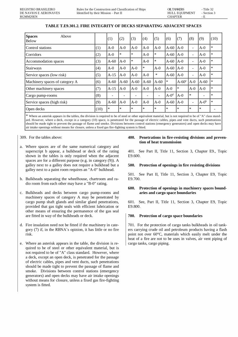
TABLE T.E9.301.2. FIRE INTEGRITY OF DECKS SEPARATING ADJACENT SPACES
Spaces Above
Below (1) (2) (3) (4) (5) (6) (7) (8) (9) (10)
Control stations (1) A-0 A-0 A-0 A-0 A-0 A-60 A-0 - A-0 *
Corridors (2) A-0 * * A-0 * A-60 A-0 - A-0 *
Accommodation spaces (3) A-60 A-0 * A-0 * A-60 A-0 - A-0 *
Stairways (4) A-0 A-0 A-0 * A-0 A-60 A-0 - A-0 *
Service spaces (low risk) (5) A-15 A-0 A-0 A-0 * A-60 A-0 - A-0 *
Machinery spaces of category A (6) A-60 A-60 A-60 A-60 A-60 * A-60e A-0 A-60 *
Other machinery spaces (7) A-15 A-0 A-0 A-0 A-0 A-0 * A-0 A-0 *
Cargo pump-rooms (8) - - - - - A-0d A-0 * - *
Service spaces (high risk) (9) A-60 A-0 A-0 A-0 A-0 A-60 A-0 - A-0b *
Open decks (10) * * * * * * * * * -
* Where an asterisk appears in the tables, the division is required to be of steel or other equivalent material, but is not required to be of "A" class stand-
ard. However, where a deck, except in a category (10) space, is penetrated for the passage of electric cables, pipes and vent ducts, such penetrations
should be made tight to prevent the passage of flame and smoke. Divisions between control stations (emergency generators) and open decks may have
air intake openings without means for closure, unless a fixed gas fire-fighting system is fitted.
309. For the tables above:
a. Where spaces are of the same numerical category and
superscript b appear, a bulkhead or deck of the rating
shown in the tables is only required when the adjacent
spaces are for a different purpose (e.g. in category (9)). A
galley next to a galley does not require a bulkhead but a
galley next to a paint room requires an "A-0" bulkhead.
b. Bulkheads separating the wheelhouse, chartroom and ra-
dio room from each other may have a "B-0" rating.
c. Bulkheads and decks between cargo pump-rooms and
machinery spaces of category A may be penetrated by
cargo pump shaft glands and similar gland penetrations,
provided that gas tight seals with efficient lubrication or
other means of ensuring the permanence of the gas seal
are fitted in way of the bulkheads or deck.
d. Fire insulation need not be fitted if the machinery in cate-
gory (7) if, in the RBNA’s opinion, it has little or no fire
risk.
e. Where an asterisk appears in the table, the division is re-
quired to be of steel or other equivalent material, but is
not required to be of "A" class standard. However, where
a deck, except an open deck, is penetrated for the passage
of electric cables, pipes and vent ducts, such penetrations
should be made tight to prevent the passage of flame and
smoke. Divisions between control stations (emergency
generators) and open decks may have air intake openings
without means for closure, unless a fixed gas fire-fighting
system is fitted.
400. Penetrations in fire-resisting divisions and preven-
tion of heat transmission
401. See Part II, Title 11, Section 3, Chapter E9., Topic
E9.600.
500. Protection of openings in fire resisting divisions
501. See Part II, Title 11, Section 3, Chapter E9, Topic
E9.700.
600. Protection of openings in machinery spaces bound-
aries and cargo space boundaries
601. See, Part II, Title 11, Section 3, Chapter E9, Topic
E9.800.
700. Protection of cargo space boundaries
701. For the protection of cargo tanks bulkheads in oil tank-
ers carrying crude oil and petroleum products having a flash
point not over 60°C, materials which easily melt under the heat of a fire are not to be uses in valves, air vent piping of
cargo tanks, cargo piping.

REGISTRO BRASILEIRO Rules for the Construction and Classification of Ships OIL TANKERS - Title 32
DE NAVIOS E AERONAVES Identified by their Mission – Part II HULL EQUIPMENT - Section 3
RGMM20EN CHAPTER - E
E11. FIRE FIGHTING
100. Scope
101. The requirements of the present Subchapter E11 are
additional to the those of Part II, Title 11, Section 3, Chapter
E, Subchapter E11.
200. Fixed firefighting systems
201. The installation of adequate fixed firefighting systems
in oil tankers is mandatory for the following locations:
a. Machinery compartments category A;
b. Pump room when located under the mains deck;
c. Compartments containing essential equipment such as
diesel generators, distribution panels, air compressors,
etc.
d. Machinery for frigorific installations.
202. The fixed firefighting systems are to be in accordance
with the relevant Chapter of the IMO FSS Code, Chapter 5, “Fixed gas fire extinguishing”.
300. Fire fighting systems on deck
301. Every oil tanker is to be fitted with a foam system on
deck for the protection of the cargo tanks.
302. The foam system shall be in accordance with the IMO
FSS Code, Chapter 15, “Fixed deck foam systems”.
303. Special cases, such as the installation of portable foam
systems, shall be analysed by RBNA.
E12. MEANS OF ESCAPE
100. Purpose
101. Purpose: swiftly escape to the lifeboat and liferaft em-
barkation deck. For this purpose, the following functional
requirements shall be met:
a. safe escape routes shall be provided;
b. escape routes shall be maintained in a safe condition,
clear of obstacles; and
c. additional aids for escape shall be provided as necessary
to ensure accessibility, clear marking, and adequate de-
sign for emergency situations.
Guidance
Emergency exit hatches to open deck
To facilitate a swift and safe means of escape to the lifeboat
and liferaft embarkation deck, the following provisions apply
to overhead hatches fitted along the escape routes addressed
by Subchapter E12.:
a. the securing devices shall be of a type which can be
opened from both sides;
b. the maximum force needed to open the hatch cover shall
not exceed 150 N; and
c. the use of a spring equalizing, counterbalance or other
suitable device on the hinge side to reduce the force
needed for opening is acceptable.
End of guidance4
200. General requirements
201. Unless expressly provided otherwise in this regulation,
at least two widely separated and ready means of escape shall
be provided from all spaces or groups of spaces.
202. Fits shall not be considered as forming one of the
means of escape as required by this Subchapter.
300. Means of escape from control stations, accommo-
dation spaces and service spaces
301. Stairways and ladders shall be so arranged as to provide
ready means of escape to the lifeboat and liferaft embarka-
tion deck from passenger and crew accommodation spaces
and from spaces in which the crew is normally employed,
other than machinery spaces.
302. Unless expressly provided otherwise in this regulation,
a corridor, lobby, or part of a corridor from which there is
only one route of escape shall be prohibited. Dead-end cor-
ridors used in service areas which are necessary for the prac-tical utility of the ship, such as fuel oil stations and athwart-
ships supply corridors, shall be permitted, provided such
dead-end corridors are separated from crew accommodation
areas and are inaccessible from passenger accommodation
areas. Also, a part of a corridor that has a depth not exceed-
ing its width is considered a recess or local extension and is
permitted.
303. All stairways in accommodation and service spaces and
control stations shall be of steel frame construction except
where RBNA sanctions the use of other equivalent material.
304. If a radiotelegraph station has no direct access to the
open deck, two means of escape from, or access to, the sta-
tion shall be provided, one of which may be a porthole or
window of sufficient size or other means to the satisfaction of
RBNA.
305. Doors in escape routes shall, in general, open in way of
the direction of escape, except that:
a. individual cabin doors may open into the cabins in order to avoid injury to persons in the corridor when the door is
opened; and

REGISTRO BRASILEIRO Rules for the Construction and Classification of Ships OIL TANKERS - Title 32
DE NAVIOS E AERONAVES Identified by their Mission – Part II HULL EQUIPMENT - Section 3
RGMM20EN CHAPTER - E
b. doors in vertical emergency escape trunks may open out
of the trunk in order to permit the trunk to be used both for escape and for access.
307. Means of escape in oil tankers
a. General: at all levels of accommodation there shall be
provided at least two widely separated means of escape
from each restricted space or group of spaces.
b. Escape from spaces below the lowest open deck: below
the lowest open deck the main means of escape shall be a
stairway and the second escape may be a trunk or a stair-
way.
c. Escape from spaces above the lowest open deck: above
the lowest open deck the means of escape shall be stair-
ways or doors to an open deck or a combination thereof.
d. Dead-end corridors: no dead-end corridors having a
length of more than 7 m shall be accepted.
e. Width and continuity of escape routes: the width, num-
ber and continuity of escape routes shall be in accordance
with the requirements in the Fire Safety Systems Code.
f. Dispensation from two means of escape: exceptionally,
RBNA may dispense with one of the means of escape, for
crew spaces that are entered only occasionally, if the re-
quired escape route is independent of watertight doors.
308. Emergency escape breathing devices*
a. Refer to the Guidelines for the performance, location, use
and care of emergency escape breathing devices. (IMO
MSC/Circ.849)
b. Emergency escape breathing devices shall comply with
the Fire Safety Systems Code. Spare emergency escape
breathing devices shall be kept on board.
c. All ships shall carry at least two emergency escape
breathing devices within accommodation spaces.
d. In all passenger ships, at least two emergency escape
breathing devices shall be carried in each main vertical
zone.
e. In all passenger ships carrying more than 36 passengers,
two emergency escape breathing devices, in addition to
those required in paragraph 3.4.3 above, shall be carried
in each main vertical zone.
f. However, Paragraphs E12.308.d. and E12.308.e. do not
apply to stairway enclosures which constitute individual
main vertical zones and to the main vertical zones in the
fore or aft end of a ship which do not contain spaces of
categories (6), (7), (8) or (12) as defined in Tables
T.E9.301.1. and T.E9.301.2.
400. Means of escape from machinery spaces
401. Means of escape from unattended machinery spac-
es:
a. Escape from machinery control rooms: Two means of
escape shall be provided from a machinery control room
located within a machinery space, at least one of which
will provide continuous fire shelter to a safe position out-
side the machinery space.
402. Escape from machinery spaces of category A: except
as provided in Paragraph E12.402.b., two means of escape
shall be provided from each machinery space of category A.
In particular, one of the following provisions shall be com-
plied with:
a. two sets of steel ladders, as widely separated as possible,
leading to doors in the upper part of the space, similarly
separated and from which access is provided to the open
deck. One of these ladders shall be located within a pro-
tected enclosure that satisfies Topic E9.300., category (4),
from the lower part of the space it serves to a safe posi-
tion outside the space. Self-closing fire doors of the same
fire integrity standards shall be fitted in the enclosure.
The ladder shall be fixed in such a way that heat I s not
transferred into the enclosure through non-insulated fix-ing points. The enclosure shall have minimum internal
dimensions of at least 800 mm x 800 mm, and shall have
emergency lighting provisions; or
b. one steel ladder leading to a door in the upper part of the
space from which access is provided to the open deck
and, additionally, in the lower part of the space and in a
position well separated from the ladder referred to, a steel
door capable of being operated from each side and which
provides access to a safe escape route from the lower part
of the space to the open deck.
c. Dispensation from two means of escape: escape required
under Item E12.402.a., due regard being paid to the di-
mension and disposition of the upper part of the space. In
addition, the means of escape from machinery spaces of
category A need not comply with the requirement for an
enclosed fire shelter listed in Item E12.402.a. first item.
In the steering gear space, a second means of escape shall
be provided when the emergency steering position is lo-
cated in that space unless there is direct access to the open
deck. From machinery spaces other than those of catego-
ry A, two escape routes shall be provided except that a single escape route may be accepted for spaces that are
entered only occasionally, and for spaces where the max-
imum travel distance to the door is 5 m or less.
500. Emergency escape breathing devices
501. On all ships, within the machinery spaces, emergency
escape breathing devices shall be situated ready for use at
easily visible places, which can be reached quickly and easily
at any time in the event of fire. The location of emergency
escape breathing devices shall take into account the layout of the machinery space and the number of persons normally
working in the spaces.

REGISTRO BRASILEIRO Rules for the Construction and Classification of Ships OIL TANKERS - Title 32
DE NAVIOS E AERONAVES Identified by their Mission – Part II HULL EQUIPMENT - Section 3
RGMM20EN CHAPTER - E
502. Refer to the Guidelines for the performance, location,
use and care of emergency escape breathing devices. (MSC/Circ.849)
503. The number and location of these devices shall be indi-
cated in the fire control plan.
504. Emergency escape breathing devices shall comply with
the Fire Safety Systems Code.

REGISTRO BRASILEIRO Rules for the Construction and Classification of Ships OIL TANKERS - Title 32
DE NAVIOS E AERONAVES Identified by their Mission – Part II HULL EQUIPMENT - Section 3
RGMM20EN CHAPTER - E
CHAPTER F
FIRE FIGHTING FOR OIL TANKERS WITH GT < 500
CHAPTER CONTENTS
F1. APPLICATION
F2. FIRE PUMPS AND FIRE MAIN PIPING
See Part II, Title 11, Section 6, Subchapter F2
F3. FIRE SAFETY MEASURES
F4. FIXED FIRE FIGHTING SYSTEMS
F5. FIRE-FIGHTING EQUIPMENT
F6. DETECTION AND ALARM
F7. ALTERNATIVE DESIGN AND ARRANGE-
MENTS
F7. REQUIREMENTS FOR NON-PROPELLED OIL
TANKER BARGES
F1. APPLICATION
100. Application
101. The requirements of the present Chapter F are addi-
tional to those of Part II, Title 11, Section 3, Chapter F and
apply to oil tankers under 500 GT classes K1n, K2 and K3
for open sea navigation.
102. Statutory regulations apply as follows:
a. For vessel under the Brazilian Flag, the regulations of
NORMAM 01;
b. For vessels under foreign flags, the National regula-
tions;
c. Where there are no National regulations, the IMO
MARPOL and SOLAS regulations apply as far as pos-
sible;
d. Where there is conflict between the Rules and the Na-
tional requirements, the stricter regulations are to be
adopted.
102. Vessels carrying Chemicals in Bulk or Gas Carriers
are subject to the IMO Bulk Chemical Code and to the
IMO International Gas Carried Cod, according to Chapter
3, Section I, item 302 of NORMAM 01.
200. Fire safety objectives
201. The fire safety objectives of this chapter are to:
a. prevent the occurrence of fire and explosion;
b. reduce the risk to life caused by fire;
c. reduce the risk of damage caused by fire to the tanker, its
cargo and the environment;
d. contain, control and suppress fire and explosion in the
compartment of origin; and provide adequate and readily
accessible means of escape for crew.
300. Achievement of the fire safety objectives
301. The fire safety objectives set out above could be
achieved by ensuring compliance with Subchapters F1 to F5
or by alternative design and arrangements which comply with
Subchapter F6.
302. A ship could be considered to achieve the fire safety
objectives set out in first paragraph when either:
a. the tanker's designs and arrangements, as a whole, com-
ply with Subchapters F1 to F5, as applicable;
b. the tanker’s designs and arrangements, as a whole, have
been reviewed and approved; or else part(s) of the ves-
sel's designs and arrangements have been reviewed and
approved; and
c. the remaining parts of the tanker comply with the relevant
requirements of Subchapters F1 to F5.
F3. FIRE SAFETY MEASURES
100. Purpose
101. The purpose of this regulation shall contain a fire in the
space of origin. For this purpose, the following functional
Recommendations shall be met:
a. the oil tanker shall be subdivided by thermal and structur-
al boundaries;
b. thermal insulation of boundaries shall have due regard to the fire risk of the space and adjacent spaces;
c. the fire integrity of the divisions shall be maintained at
openings and penetrations.
200. Structural fire protection
201. The minimum fire integrity of bulkheads and decks
shall be as prescribed in Table T.F3.201.1.

REGISTRO BRASILEIRO Rules for the Construction and Classification of Ships OIL TANKERS - Title 32
DE NAVIOS E AERONAVES Identified by their Mission – Part II HULL EQUIPMENT - Section 3
RGMM20EN CHAPTER - F
TABLE T.F3.201.1. MINIMUM FIRE INTEGRITY OF BULKHEADS AND DECKS
Item Compartment Separated by Separated from the compartment
1
Compartment of Class A machinery
service spaces, compartments of high-risk
vehicle
A-60
Accommodations / control stations / gangways /
stairs / service spaces of greater fire risk / compart-
ment for vehicles
2 Compartment of Class A machinery A-0 Other compartments other than those of item 1
3 Kitchen A-0 Unless specified otherwise
4 Service space with greater fire risk except
the kitchen B-15 Unless specified above (item 1)
5 Corridor
Stairs B-0 Unless specified above (item 1)
6 Cargo compartment (except Ro-Ro com-
partment and compartments for vehicles) A-0 Unless specified above (item 1)
202. Category ‘A’ machinery spaces shall be enclosed by A-
60 Class divisions, where adjacent to:
a. Accommodation spaces
b. Control stations
c. Corridors and staircases
d. Service spaces of high fire risk,
e. and by A-0 Class divisions elsewhere.
Note: The divisions used to separate spaces, not mentioned
above, shall be of non-combustible material.
203. The hull, superstructure, structural bulkheads, decks
and deckhouses shall be constructed of steel or other equiva-
lent material. For the purpose of applying the definition of
steel or other equivalent material, as given in SOLAS, the
'applicable fire exposure' shall be one hour. Tankers built of
materials other than steel shall be specially considered.
204. Stairways shall be enclosed, at least at one level, by
divisions and doors or hatches, in order to restrict the free
flow of smoke to other decks in the vessel and the supply of
air to the fire. Doors forming such enclosures shall be self-
closing.
205. Openings in 'A' Class divisions shall be provided with
permanently attached means of closing which shall be at least
as effective for resisting fires as the divisions in which they
are fitted.
206. Interior stairways serving machinery spaces, accommo-
dation spaces, service spaces or control stations shall be of
steel or other equivalent material.
207. Doors shall be self-closing in way of Category 'A' ma-chinery spaces and galleys, except where they are normally
kept closed.
208. Where 'A' Class divisions are penetrated for the passage
of electric cables, pipes, trunks, ducts, etc., or for girders,
beams or other structural members, arrangements shall be
made to ensure that the fire resistance is not impaired. Ar-
rangements shall also prevent the transmission of heat to un-
insulated boundaries at the intersections and terminal points
of the divisions and penetrations by insulating the horizontal and vertical boundaries or penetrations for a distance of 450
mm.
300. Materials
301. Paints, varnishes and other finishes used on exposed
interior surfaces shall not be capable of producing excessive
quantities of smoke, toxic gases or vapours and shall be of
the low flame spread type in accordance with the IMO FTP
Code, Annex 1, Parts 2 and 5.
302. Except in cargo spaces or refrigerated compartments of
service spaces, insulating materials shall be non-combustible.
303. Where pipes penetrate 'A' or ‘B’ Class divisions, the
pipes or their penetration pieces shall be of steel or other ap-
proved materials having regard to the temperature and integ-
rity recommendations such divisions are required to with-
stand.
304. Pipes conveying oil or combustible liquids for ship op-
eration through accommodation and service spaces shall be
of steel or other approved materials having regard to the fire risk.
305. Materials readily rendered ineffective by heat shall not
be used for overboard scuppers, sanitary discharges and other
outlets which are close to the waterline, and where the failure
of the material in the event of fire would give rise to the dan-
ger of flooding.
306. Primary deck coverings within accommodation spaces,
service spaces and control stations shall be of a type which
will not readily ignite, or give rise to toxic or explosive haz-ards at elevated temperatures in accordance with the IMO
FTP Code, Annex 1, Parts 2 and 6.
307. Materials used for insulating pipes, etc., in machinery
spaces and other compartments containing high fire risks

REGISTRO BRASILEIRO Rules for the Construction and Classification of Ships OIL TANKERS - Title 32
DE NAVIOS E AERONAVES Identified by their Mission – Part II HULL EQUIPMENT - Section 3
RGMM20EN CHAPTER - F
shall be non-combustible. Vapour barriers and adhesives
used in conjunction with insulation, as well as the insulation of pipe fittings, for cold service systems practicable and their
exposed surfaces shall have low flame spread characteristics.
400. Surface of insulation
401. In spaces where penetration of oil products is possible,
the surface of the insulation shall be impervious to oil or oil
vapours. Insulation boundaries shall be arranged to avoid
immersion in oil spillage.
500. Ventilation systems
501. Ventilation fans shall be capable of being stopped and
main inlets and outlets of ventilation systems closed from
outside the spaces being served.
502. Ventilation ducts for accommodation spaces, service
spaces or control stations shall not pass through Category 'A'
machinery spaces or galleys unless the ducts are constructed
of steel and arranged to preserve the integrity of the division.
503. Ventilation arrangement for store rooms containing
highly flammable products shall be specially considered.
504. Ventilation systems serving Category 'A' machinery
spaces and galley exhaust ducts shall be independent of sys-
tems serving other spaces.
505. Ventilation shall be provided to prevent the accumula-
tion of gases that may be emitted from batteries.
506. Ventilation openings may be fitted in and under the
lower parts of cabin, mess and dayroom doors in corridor
bulkheads. The total net area of any such openings is not to
exceed 0,05 m². Balancing ducts shall not be permitted in fire divisions.
600. Oil fuel arrangements
601. In a cargo vessel in which oil fuel is used, the arrange-
ments for the storage, distribution and utilization of the oil
fuel shall be such as to ensure the safety of the vessel and
persons on board.
602. Oil fuel tanks situated within the boundaries of Catego-
ry 'A' machinery spaces shall not contain oil fuel having a flashpoint of less than 60°C.
603. Oil fuel, lubricating oil and other flammable oils shall
not be carried in fore peak tanks.
604. For tankers of 150 GT or more, and as far as practica-
ble:
a. oil fuel lines shall be arranged far apart from hot surfac-
es, electrical installations or other sources of ignition and
shall be screened or otherwise suitably protected to avoid oil spray or oil leakage onto the sources of igni-
tion. The number of joints in such piping systems shall
be kept to a minimum.
b. surfaces with temperatures above 220°C which may be
impinged as a result of a fuel system failure shall be properly insulated. Precautions shall be taken to prevent
any oil that may escape under pressure from any pump,
filter or heater from coming into contact with heated sur-
faces.
c. External high-pressure fuel delivery lines between the
high pressure fuel pumps and fuel injectors shall be pro-
tected with a jacketed piping system capable of contain-
ing fuel from a high-pressure line failure. A suitable en-
closure on engines having an output of 375 kW or less
having fuel injection pumps serving more than one inject
or may be used as an alternative to the jacketed piping system.
700. Special arrangements in Category 'A' machinery
spaces and where necessary other machinery spac-
es
701. The number of skylights, doors, ventilators, openings in
funnels to permit exhaust ventilation and other openings to
machinery spaces shall be reduced to a minimum consistent
with the needs of ventilation and the proper and safe working
of the cargo vessel.
702. Skylights shall be of steel and are not to contain glass
panels. Suitable arrangements shall be made to permit the
release of smoke, in the event of fire, from the
space to be protected.
703. Windows shall not be fitted in machinery space bound-
aries. This does not preclude the use of glass in control
rooms within the machinery spaces.
704. Means of control shall be provided for:
a. opening and closure of skylights, closure of openings in
funnels which normally allow
b. exhaust ventilation, and closure of ventilator dampers;
c. permitting the release of smoke;
d. closing power-operated doors or actuating release mech-
anism on doors other than power-operated watertight
doors;
e. stopping ventilating fans; and
f. stopping forced and induced draught fans, oil fuel trans-
fer pumps, oil fuel unit pump sand other similar fuel
pumps.
705. The controls required in Paragraph F3.704. above shall
be located outside the space concerned, where they will not
be cut off in the event of fire in the space they serve. Such
controls and the controls for any required fire-extinguishing
system shall be situated at one control position or grouped in as few positions as possible. Such positions shall have a safe
access from the open deck.

REGISTRO BRASILEIRO Rules for the Construction and Classification of Ships OIL TANKERS - Title 32
DE NAVIOS E AERONAVES Identified by their Mission – Part II HULL EQUIPMENT - Section 3
RGMM20EN CHAPTER - F
800. Arrangements for gaseous fuel for domestic
purposes and oil heating
801. Where gaseous fuel is used for domestic purposes, the
arrangements for the storage, distribution and utilization of
the fuel shall be specially considered.
802. Space heaters, if used, shall be fixed in position and so
constructed as to reduce fire risks to a minimum. The design
and location of these units shall be such that clothing, cur-
tains or other similar materials cannot be scorched or set on
fire by heat from the unit.
900. Means of escape
901. Purpose: the purpose of this Recommendation is to
provide means of escape so that persons on board can safely
and swiftly escape to the lifeboat and life raft embarkation
deck. For this purpose, the following functional Recommen-
dations shall be met:
a. safe escape routes shall be provided;
b. escape routes shall be maintained in a safe condition,
clear of obstacles; and
c. additional aids for escape shall be provided as necessary
to ensure accessibility, clear marking, and adequate de-
sign for emergency situations.
902. Stairways, ladders and corridors serving crew spaces
and other spaces to which the crew normally have access
shall be arranged so as to provide ready means of escape to a
deck from which embarkation into survival craft may be ef-
fected.
903. There shall be at least two means of escape, as widely separated as possible, from each section of accommodation
and service spaces and control stations.
a. The normal means of access to the accommodation and
service spaces below the open deck shall be arranged so
that it is possible to reach the open deck without passing
through spaces containing a possible source of fire (e.g.
machinery spaces, storage spaces of flammable liquids).
b. The second means of escape may be through portholes
or hatches of adequate size and preferably leading direct-ly to the open deck.
c. Dead-end corridors having a length of more than 7m
shall not be accepted.
903. At least two means of escape shall be provided from
machinery spaces, except where the small size of a machin-
ery space makes it impracticable. Escape shall be by steel
ladders that shall be as widely separated as possible.
F4. FIXED FIRE FIGHTING SYSTEMS
100. Purpose
101. The purpose of this Subchapter F4. is to suppress and
swiftly extinguish a fire in the space of origin. For this pur-
pose, the following functional requirements shall be met:
a. fixed fire-extinguishing systems shall be installed, as
applicable, having due regard to the fire growth potential
of the protected spaces; and
b. fire-extinguishing appliances shall be readily available.
200. Fixed fire-extinguishing arrangements in Category
'A' machinery spaces
201. For machinery spaces of category 'A' on vessels with
GT greater than or equal to 150 and operating in unrestricted
or restricted waters, the provision of an approved fixed fire
extinguishing system is to be installed.
202. Machinery spaces of category 'A' on vessels operating
in protected areas may be exempted from this recommenda-
tion.
203. Fixed fire-fighting systems where required, shall be in
accordance with the requirements of the IMO FSS Code.
300. Protection of paint lockers and flammable liquid
lockers
301. The recommendations for the protection of paint lock-
ers and flammable liquids lockers shall be specially consid-
ered.
400. Portable Fire-extinguishers
401. See Subchapter D5. above.
500. Deck Foam Systems
501. At least one portable foam applicator unit must be in-
stalled on deck in the oil collection zone to protect the oil
collection tanks, consisting of:
a. the. a foam nozzle / bypass tube, capable of being con-
nected to the fire network by a fire hose, together with a portable tank containing at least 20 l of foam concen-
trate.
b. a spare foam concentrate tank with the same capacity.
502. The foam applicator unit must be capable of producing
effective foam suitable for extinguishing an oil fire, at a foam
solution flow of at least 200 l/min at rated pressure in the fire
network.

REGISTRO BRASILEIRO Rules for the Construction and Classification of Ships OIL TANKERS - Title 32
DE NAVIOS E AERONAVES Identified by their Mission – Part II HULL EQUIPMENT - Section 3
RGMM20EN CHAPTER - F
F5. FIRE FIGHTING EQUIPMENT
100. General
101. The fire-fighting equipment shall comply with the re-
quirements specified below, regardless of service in areas 01
or 02.
200. Fire blanket
201. A fire blanket shall be provided.
300. Fire-fighter’s outfit (which includes an axe)
301. Types of fire-fighter's outfits: Firefighter's outfits
shall comply with the Fire Safety Systems Code.
302. Number of fire-fighter's outfits: Oil tankers shall car-
ry at least two fire-fighter's outfits.
303. Where certain products (such as K1n) require, a self-
breathing apparatus shall be fitted in number equal to the
firefighters’ outfits.
400. Safety Plan and Fire Fighting Plan
401. In all oil tankers fire control plans shall comply with
NORMAM 1, Annex 3-F and shall be permanently exhibited
for the guidance of the vessel's officers, using graphical sym-
bols that are in accordance with IMO Resolution A.952(23),
which show clearly for each deck the control stations, the
various fire sections enclosed by steel or 'A' Class divisions,
together with particulars of:
a. the fire detection and fire-alarm systems;
b. fixed fire-fighting system, when fitted;
c. the fire-extinguishing appliances;
d. the means of access to different compartments, decks,
etc.;
e. the ventilating system, including particulars of the fan
control positions, the position of dampers and identifica-
tion numbers of the ventilating fans serving each section;
and
f. the location and arrangement of the emergency stop for
the oil fuel unit pump sand for closing the valves on the
pipes from oil fuel tanks.
402. The plans shall be kept up to date, any alterations being
recorded thereon as soon as practicable. Description in such
plans shall be in the official language of the Flag State. In
addition, instructions concerning the maintenance and opera-
tion of all the equipment and installations on board for the
fighting and containment of fire shall be kept under one cov-
er, readily available in an accessible position.
403. In all cargo vessels greater than or equal to 150 GT, a
duplicate set of fire-control plans shall be permanently stored
in a prominently marked weather tight enclosure outside the
deckhouse for the assistance of shore side fire fighting per-sonnel.
F6. DETECTION AND ALARM
100. Protection of machinery spaces
101. Installation: a fixed fire detection and fire alarm sys-
tem shall be installed in:
a. Class A machinery spaces where the total installed power is 750 kWh and larger;
b. periodically unattended machinery spaces; and
c. machinery spaces where:
c.1. the installation of automatic and remote control
systems and equipment has been approved in lieu
of continuous manning of the space; and
c.2. the main propulsion and associated machinery in-cluding sources of the main sources of electrical
power, are provided with various degrees of auto-
matic or remote control and are under continuous
manned supervision from a control room.
102. The requirements for the fixed fire detection and alarm
systems are according to Subchapter E7. above, as relevant.
F7. ALTERNATIVE DESIGN AND ARRANGE-
MENTS
100. General
101. Fire safety design and arrangements may deviate from
Subchapters F1. to F6. of this Chapter, provided that the de-
sign and arrangements meet the fire safety objectives and the
functional recommendations, and the regulations of NOR-
MAM 01, Chapter 5.
102. When fire safety design or arrangements deviate from
the requirements of this Chapter, engineering analysis, evalu-ation and approval of the alternative design and arrangements
shall be carried out in accordance with this regulation.* * Reference can be made to MSC/Circ. 1002 Guidelines on alternative de-
sign and arrangements for fire safety
200. Engineering analysis
201. The engineering analysis shall be prepared and submit-
ted to RBNA based on the guidelines developed by the Inter-
national Maritime Organization and shall include, as a mini-mum, the following elements:
a. determination of the vessel type and space(s) concerned;
b. identification of recommendation(s) with which the ves-

REGISTRO BRASILEIRO Rules for the Construction and Classification of Ships OIL TANKERS - Title 32
DE NAVIOS E AERONAVES Identified by their Mission – Part II HULL EQUIPMENT - Section 3
RGMM20EN CHAPTER - F
sel or the space(s) will not comply;
c. identification of the fire and explosion hazards of the
vessel or the space(s)concerned:
c.1. identification of the possible ignition sources;
c.2. identification of the fire growth potential of each
space concerned;
c.3. identification of the smoke and toxic effluent gener-
ation potential for each space concerned;
c.4. identification of the potential for the spread of fire, smoke or of toxic effluents from the space(s) con-
cerned to other spaces;
d. determination of the required fire safety performance
criteria for the vessel or the space(s) concerned:
d.1. performance criteria shall be based on the fire safety
objectives and on the functional Recommendations
of this Chapter;
d.2. performance criteria shall provide a degree of safety not less than that achieved the recommendation in
Subchapters F1. to F6.; and
d.3. performance criteria shall be quantifiable and meas-
urable;
e. detailed description of the alternative design and ar-
rangements, including a list of the assumptions used in
the design and any proposed operational restrictions or
conditions; and
f. technical justification demonstrating that the alternative design and arrangements meet the required fire safety
performance criteria.
300. Evaluation of the alternative design and arrange-
ments
301. The engineering analysis required in Topic F7.200.
shall be evaluated and approved by RBNA taking into ac-
count the guidelines developed by the International Maritime
Organization and the requirements of NORMAM 01.
302. A copy of the documentation, as approved by RBNA,
indicating that the alternative design and arrangements com-
ply with this regulation shall be carried on board the vessel.
400. Re-evaluation due to change of conditions
401. If the assumptions, and operational restrictions that
were stipulated in the alternative design and arrangements are
changed, the engineering analysis shall be carried out under
the changed condition and shall be approved by RBNA.
F8. REQUIREMENTS FOR NON-PROPELLED
VESSELS
100. Basic requirements
101. Arrangements for fire protection, detection and extinc-
tion in vessels not fitted with propelling machinery shall be
specially considered in each case and shall depend on the size
and purpose of the vessel and the presence of accommoda-
tion spaces, machinery and combustible materials on board.
102. The requirements of NORMAM 01, item 0522 and fol-
lowing shall be complied with.
Rgmm20en-PIIT32S3-adef-00