Chapter9 Calibration
54
301 Chapter 9 CALIBRATION OF PHOTON AND ELECTRON BEAMS P. ANDREO Department of Medical Radiation Physics, University of Stockholm, Karolinska Institute, Stockholm, Sweden J.P. SEUNTJENS, E.B. PODGORSAK Department of Medical Physics, McGill University Health Centre, Montreal, Quebec, Canada 9.1. INTRODUCTION Modern radiotherapy relies on accurate dose delivery to the prescribed target volume. The ICRU has recommended an overall accuracy in tumour dose delivery of ±5%, based on an analysis of dose response data and on an evaluation of errors in dose delivery in a clinical setting. Considering all uncer- tainties involved in the dose delivery to the patient, the ±5% accuracy recom- mendation is by no means easy to attain. Before clinical use, the output of photon and electron beams produced by external beam radiotherapy machines must be calibrated. This basic output calibration is but one, albeit very important, of the links constituting the chain representing an accurate dose delivery to the patient. The other links refer to: the procedures for measurement of relative dose data, equipment commis- sioning and quality assurance; treatment planning; and the actual patient set-up on the treatment machine. ● The basic output for a radiotherapy machine is usually stated as the dose rate for a point P at a reference depth z ref (often the depth of dose maximum z max ) in a water phantom for a nominal source to surface distance (SSD) or source to axis distance (SAD) and a reference field size (often 10 × 10 cm 2 ) on the phantom surface or the isocentre. The output for kilovoltage X ray generators and teletherapy units is usually given in Gy/min, while for clinical accelerators it is given in Gy/MU. ● For superficial and orthovoltage beams and occasionally for beams produced by teletherapy radioisotope machines, the basic beam output
-
Upload
mahmoud-el-attar -
Category
Documents
-
view
174 -
download
4
Transcript of Chapter9 Calibration
301
Chapter 9
CALIBRATION OF PHOTON AND ELECTRON BEAMS
P. ANDREODepartment of Medical Radiation Physics,University of Stockholm, Karolinska Institute,Stockholm, Sweden
J.P. SEUNTJENS, E.B. PODGORSAKDepartment of Medical Physics,McGill University Health Centre,Montreal, Quebec, Canada
9.1. INTRODUCTION
Modern radiotherapy relies on accurate dose delivery to the prescribed target volume. The ICRU has recommended an overall accuracy in tumour dose delivery of ±5%, based on an analysis of dose response data and on an evaluation of errors in dose delivery in a clinical setting. Considering all uncer-tainties involved in the dose delivery to the patient, the ±5% accuracy recom-mendation is by no means easy to attain.
Before clinical use, the output of photon and electron beams produced by external beam radiotherapy machines must be calibrated. This basic output calibration is but one, albeit very important, of the links constituting the chain representing an accurate dose delivery to the patient. The other links refer to: the procedures for measurement of relative dose data, equipment commis-sioning and quality assurance; treatment planning; and the actual patient set-up on the treatment machine.
● The basic output for a radiotherapy machine is usually stated as the dose rate for a point P at a reference depth zref (often the depth of dose maximum zmax) in a water phantom for a nominal source to surface distance (SSD) or source to axis distance (SAD) and a reference field size (often 10 × 10 cm2) on the phantom surface or the isocentre. The output for kilovoltage X ray generators and teletherapy units is usually given in Gy/min, while for clinical accelerators it is given in Gy/MU.
● For superficial and orthovoltage beams and occasionally for beams produced by teletherapy radioisotope machines, the basic beam output

CHAPTER 9
302
may also be stated as the air kerma rate in air (Gy/min) at a given distance from the source and for a given nominal collimator or applicator setting.
The basic output calibration of photon and electron beams is carried out with radiation dosimeters and special radiation dosimetry techniques. Radiation dosimetry refers to a determination by measurement and/or calculation of the absorbed dose or some other physically relevant quantity, such as air kerma, fluence or equivalent dose, at a given point of interest in a given medium.
A radiation dosimeter is defined as any device that is capable of providing a reading M that is a measure of the dose D deposited in the dosimeter’s sensitive volume V by ionizing radiation.
— A dosimeter that produces a signal from which the dose in its sensitive volume can be determined without requiring calibration in a known field of radiation is referred to as an absolute dosimeter;
— Dosimeters requiring calibration in a known radiation field are called relative dosimeters.
The basic output calibration of a clinical radiation beam, by virtue of a direct measurement of dose or dose rate in water under specific reference conditions, is referred to as reference dosimetry. Three types of reference dosimetry technique are currently known:
(a) Calorimetry; (b) Fricke dosimetry; (c) Ionization chamber dosimetry.
These dosimeters can be used as absolute dosimeters but are seldom used as such in clinics, because their use in absolute dosimetry is cumbersome and, moreover, calibration in a known radiation field offers certain advantages, such as traceabilty to a standards laboratory. When an absolute dosimeter is used independently, it relies on its own accuracy instead of referring to a standard in common with other radiation users.
9.1.1. Calorimetry
Calorimetry is the most fundamental of the three reference dosimetry techniques, since it relies on basic definitions of either electrical energy or temperature. In principle, calorimetric dosimetry is simple; in practice,
CALIBRATION OF PHOTON AND ELECTRON BEAMS
303
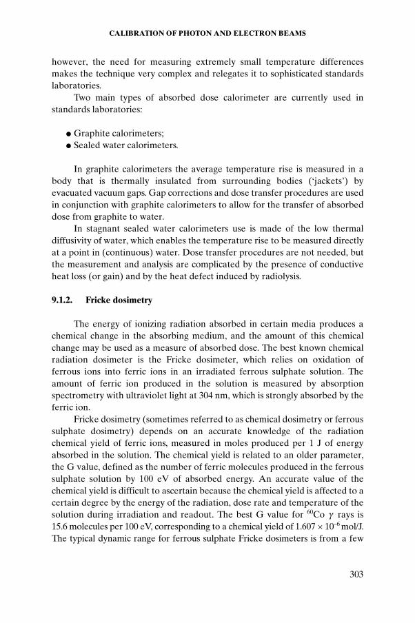
however, the need for measuring extremely small temperature differences makes the technique very complex and relegates it to sophisticated standards laboratories.
Two main types of absorbed dose calorimeter are currently used in standards laboratories:
● Graphite calorimeters;● Sealed water calorimeters.
In graphite calorimeters the average temperature rise is measured in a body that is thermally insulated from surrounding bodies (‘jackets’) by evacuated vacuum gaps. Gap corrections and dose transfer procedures are used in conjunction with graphite calorimeters to allow for the transfer of absorbed dose from graphite to water.
In stagnant sealed water calorimeters use is made of the low thermal diffusivity of water, which enables the temperature rise to be measured directly at a point in (continuous) water. Dose transfer procedures are not needed, but the measurement and analysis are complicated by the presence of conductive heat loss (or gain) and by the heat defect induced by radiolysis.
9.1.2. Fricke dosimetry
The energy of ionizing radiation absorbed in certain media produces a chemical change in the absorbing medium, and the amount of this chemical change may be used as a measure of absorbed dose. The best known chemical radiation dosimeter is the Fricke dosimeter, which relies on oxidation of ferrous ions into ferric ions in an irradiated ferrous sulphate solution. The amount of ferric ion produced in the solution is measured by absorption spectrometry with ultraviolet light at 304 nm, which is strongly absorbed by the ferric ion.
Fricke dosimetry (sometimes referred to as chemical dosimetry or ferrous sulphate dosimetry) depends on an accurate knowledge of the radiation chemical yield of ferric ions, measured in moles produced per 1 J of energy absorbed in the solution. The chemical yield is related to an older parameter, the G value, defined as the number of ferric molecules produced in the ferrous sulphate solution by 100 eV of absorbed energy. An accurate value of the chemical yield is difficult to ascertain because the chemical yield is affected to a certain degree by the energy of the radiation, dose rate and temperature of the solution during irradiation and readout. The best G value for 60Co g rays is 15.6 molecules per 100 eV, corresponding to a chemical yield of 1.607 × 10⁻⁶ mol/J. The typical dynamic range for ferrous sulphate Fricke dosimeters is from a few
CHAPTER 9
304
grays to about 400 Gy, making Fricke dosimetry impractical for routine use in a clinic.
9.1.3. Ionization chamber dosimetry
The ionization chamber is the most practical and most widely used type of dosimeter for accurate measurement of machine output in radiotherapy. It may be used as an absolute or a relative dosimeter. Its sensitive volume is usually filled with ambient air and the dose related or dose rate related measured quantities are the ionization charge Q or ionization current I, respectively, produced by radiation in the chamber sensitive air mass mair. Charge Q and air mass mair are related to absorbed dose in air Dair by:
(9.1)
where (Wair/e) is the mean energy required to produce an ion pair in air per unit charge (the current value for dry air is 33.97 eV/ion pair or 33.97 J/C).
The subsequent conversion of the air cavity dose Dair to dose to medium (usually water) Dw is based on the Bragg–Gray or Spencer–Attix cavity theories (see Chapter 2 and Section 9.4 in this chapter).
The sensitive air volume or mass in an ionization chamber is determined:
● Directly by measurement (the chamber becomes an absolute dosimeter under special circumstances);
● Indirectly through calibration of the chamber response in a known radiation field (the chamber is used as a relative dosimeter).
9.1.4. Mean energy expended in air per ion pair formed
It is generally assumed that a constant value of (Wair/e) can be used for the complete photon and electron energy range used in radiotherapy dosimetry. However, there is no direct experimental support for such an assumption, as the data available have been obtained only from measurements with 60Co and 137Cs g ray beams and 2 MV X rays. The value (Wair/e) = (33.85 ± 0.15) J/C early recommended by the ICRU came from a weighted mean value of the available experimental data, obtained mainly from absorbed dose measurements using a graphite calorimeter and a graphite ionization chamber in a graphite phantom. The two methods for deriving the absorbed dose to graphite must yield the same dose value, and one obtains:
DQ
m
W
eairair
air= ÊËÁ
ˆ¯̃
CALIBRATION OF PHOTON AND ELECTRON BEAMS
305
(9.2)
where Q is the charge collected in air mass mair and corrected for influence quantities; and sgraphite,air is the ratio of collision stopping powers for graphite and air calculated for the photon or electron beam energy used.
This method of evaluation requires a change in (Wair/e) when the stopping power ratio sgraphite,air is changed. Following the introduction of new electron stopping power data by the ICRU in 1984, the value of (Wair/e) has been modified to (33.97 ± 0.06) J/C for dry air.
Analysis of the available experimental data at higher energies, mainly for electron beams, has suggested that energy dependence in (Wair/e) cannot be ruled out, but experimental uncertainties, and the use of different stopping power ratios over the years, do not allow a definitive conclusion to be reached on this question.
It is known that the (Wair/e) value for air at a temperature of 20ºC, pressure of 101.325 kPa and 50% relative humidity is 0.6% lower than that for dry air at the same temperature and pressure, resulting in a value of 33.77 J/C instead of 33.97 J/C. Thus for the same amount of energy available for creating charge, 0.6% more charge will be created in air at 50% relative humidity than in dry air (at 20ºC and 101.325 kPa).
9.1.5. Reference dosimetry with ionization chambers
Three types of ionization chamber may be used in reference dosimetry as absolute dosimeters:
● Standard free air ionization chambers; ● Cavity ionization chambers; ● Phantom embedded extrapolation chambers.
9.1.5.1. Standard free air ionization chambers
Standard free air ionization chambers measure the air kerma in air according to its definition by collecting all ions produced by the radiation beam that result from the direct transfer of energy from photons to primary electrons in a defined volume of air. Determination of the air kerma in air or air kerma rate in air requires accurate knowledge of (Wair/e). For practical reasons related to the range of charge carriers in air, the use of the standard free air ionization chamber is limited to photon energies below 0.3 MeV.
( )( )
W eD
Q m saircalorimetry
air graphite,air
//
=
CHAPTER 9
306
9.1.5.2. Cavity ionization chambers
Cavity ionization chambers measure the air kerma in air for energies in the range from 0.6 to 1.5 MeV by making use of the Bragg–Gray cavity relationship. Analogously to standard free air ionization chambers, ions are collected in air, but this time inside a cavity with a known cavity volume surrounded by a graphite wall thick enough to provide full buildup of secondary electrons. The Bragg–Gray equation relates the dose to air in the cavity of known volume to the dose to medium in which the secondary electron spectrum is being built up (i.e. the graphite wall (for the thick walled chambers used in primary standards dosimetry laboratories (PSDLs)). The absorbed dose to the wall is related to the collision air kerma in air through the mass–energy absorption coefficient ratio, wall to air. The collision air kerma in air is related to the total air kerma in air by correcting for the fractional energy expended in radiative interactions.
In addition to the need for an accurate knowledge of the sensitive air volume, wall correction factors are required to account for the effect of photon attenuation and scattering in the chamber wall. An accurate knowledge of (Wair/e) as well as the cavity volume and radiative fraction is required to determine the air kerma (rate) in air. Finally, standards laboratories implement additional correction factors such as the point source non-uniformity correction factor and factors that account for deviations from the Spencer–Attix cavity theory.
9.1.5.3. Phantom embedded extrapolation chambers
Phantom embedded extrapolation chambers are uncalibrated variable air volume extrapolation chambers built as an integral part of a water equivalent phantom in which the dose is measured, and can serve as radiation dosimeters in the measurement of absorbed dose for megavoltage photon and electron beams. Standard dosimetry protocols are based on the Bragg–Gray or Spencer–Attix cavity theories (see Chapter 2 for details), which provide a simple linear relationship between the dose at a given point in the medium and the ratio Q/m, where Q is the ionization charge collected in mass m of air in the measuring cavity inside the medium. In extrapolation chambers, the ratio Q/m is constant and may be replaced in the cavity relationship by the derivative dQ/dm, which can be measured accurately through a controlled variation in the electrode separation. The conversion of cavity dose to dose to medium is based on the Spencer–Attix cavity theory. As in the case of the standard free air ionization chamber and the cavity ionization chamber, extrapolation chamber dosimetry relies on an accurate knowledge of the value of (Wair/e).
CALIBRATION OF PHOTON AND ELECTRON BEAMS
307
9.1.6. Clinical beam calibration and measurement chain
The theoretical aspects of the three reference dosimetry techniques discussed above are all well understood; however, none of the three techniques, for one reason or another, is practical for routine clinical use. Clinical photon and electron beams are therefore most commonly calibrated with ionization chambers that are used as relative dosimeters and have calibration coefficients determined either in air or in water and are traceable to a national PSDL. The chamber calibration coefficient essentially obviates the need for an accurate knowledge of the chamber sensitive air volume.
The standard ISO 31-0, on quantities and units, has provided guidelines with regard to the use of the terms ‘coefficient’ and ‘factor’. The former should be used for a multiplier possessing dimensions; the latter should be reserved for a dimensionless multiplier. For consistency, the widely disseminated practice of using the term ‘calibration factor’ is updated here to using ‘calibration coefficient’.
The traceability of a calibration coefficient to a national PSDL implies that:
● The chamber was calibrated directly at the PSDL in terms of the air kerma in air or absorbed dose to water; or
● The chamber was calibrated directly at an accredited dosimetry calibration laboratory (ADCL) or secondary standards dosimetry laboratory (SSDL) that traces its calibration to a PSDL; or
● The chamber calibration coefficient was obtained through a cross-calibration with another ionization chamber (user’s secondary standard), the calibration coefficient of which was measured directly at a PSDL, an ADCL or an SSDL.
9.1.7. Dosimetry protocols
The procedures to be followed when calibrating a clinical photon or electron beam are described in international or national radiation dosimetry protocols or dosimetry codes of practice; the choice of which protocol to use is largely left to individual radiotherapy departments. Dosimetry protocols are generally issued by national or regional organizations such as the American Association of Physicists in Medicine (AAPM) (North America), Institution of Physics and Engineering in Medicine and Biology (IPEMB) (UK), Deutsches Institut für Normung (DIN) (Germany), Nederlandse Commissie voor Stralingsdosimetrie (NCS) (the Netherlands and Belgium) and Nordic Association of Clinical Physics (NACP) (Scandinavia), or by international bodies such as the IAEA. This procedure ensures a high level of consistency in
CHAPTER 9
308
dose determination among different radiotherapy clinics in a given country and between one country and another.
9.2. IONIZATION CHAMBER BASED DOSIMETRY SYSTEMS
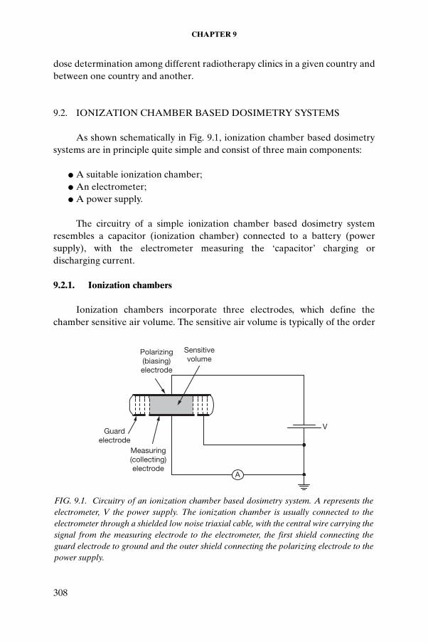
As shown schematically in Fig. 9.1, ionization chamber based dosimetry systems are in principle quite simple and consist of three main components:
● A suitable ionization chamber; ● An electrometer; ● A power supply.
The circuitry of a simple ionization chamber based dosimetry system resembles a capacitor (ionization chamber) connected to a battery (power supply), with the electrometer measuring the ‘capacitor’ charging or discharging current.
9.2.1. Ionization chambers
Ionization chambers incorporate three electrodes, which define the chamber sensitive air volume. The sensitive air volume is typically of the order
V
A
Sensitive volume
Polarizing (biasing) electrode
Guard electrode
Measuring (collecting) electrode
FIG. 9.1. Circuitry of an ionization chamber based dosimetry system. A represents the electrometer, V the power supply. The ionization chamber is usually connected to the electrometer through a shielded low noise triaxial cable, with the central wire carrying the signal from the measuring electrode to the electrometer, the first shield connecting the guard electrode to ground and the outer shield connecting the polarizing electrode to the power supply.
CALIBRATION OF PHOTON AND ELECTRON BEAMS
309
of 0.1 to 1 cm3 in ionization chambers used for the calibration of clinical photon and electron beams. The three electrodes are the:
● Polarizing electrode, which is connected directly to the power supply.● Measuring electrode, which is connected to ground through the low
impedance electrometer to measure the charge or current produced in the chamber sensitive volume.
● Guard electrode, which is directly grounded and serves two purposes: it defines the chamber sensitive volume and prevents the measurement of chamber leakage currents.
Two types of ionization chamber are used in routine beam calibration:
— Cylindrical (often referred to as thimble) chambers; — Parallel-plate (sometimes called end window or plane-parallel) chambers.
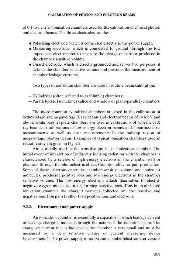
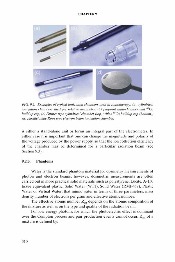
The more common cylindrical chambers are used in the calibration of orthovoltage and megavoltage X ray beams and electron beams of 10 MeV and above, while parallel-plate chambers are used in calibrations of superficial X ray beams, in calibrations of low energy electron beams and in surface dose measurements as well as dose measurements in the buildup region of megavoltage photon beams. Examples of typical ionization chambers used in radiotherapy are given in Fig. 9.2.
Air is usually used as the sensitive gas in an ionization chamber. The initial event of interaction of indirectly ionizing radiation with the chamber is characterized by a release of high energy electrons in the chamber wall or phantom through the photoelectric effect, Compton effect or pair production. Some of these electrons enter the chamber sensitive volume and ionize air molecules, producing positive ions and low energy electrons in the chamber sensitive volume. The low energy electrons attach themselves to electro-negative oxygen molecules in air, forming negative ions. Thus in an air based ionization chamber the charged particles collected are the positive and negative ions (ion pairs) rather than positive ions and electrons.
9.2.2. Electrometer and power supply
An ionization chamber is essentially a capacitor in which leakage current or leakage charge is induced through the action of the radiation beam. The charge or current that is induced in the chamber is very small and must be measured by a very sensitive charge or current measuring device (electrometer). The power supply in ionization chamber/electrometer circuits
CHAPTER 9
310
is either a stand-alone unit or forms an integral part of the electrometer. In either case it is important that one can change the magnitude and polarity of the voltage produced by the power supply, so that the ion collection efficiency of the chamber may be determined for a particular radiation beam (see Section 9.3).
9.2.3. Phantoms
Water is the standard phantom material for dosimetry measurements of photon and electron beams; however, dosimetric measurements are often carried out in more practical solid materials, such as polystyrene, Lucite, A-150 tissue equivalent plastic, Solid Water (WT1), Solid Water (RMI-457), Plastic Water or Virtual Water, that mimic water in terms of three parameters: mass density, number of electrons per gram and effective atomic number.
The effective atomic number Zeff depends on the atomic composition of the mixture as well as on the type and quality of the radiation beam.
For low energy photons, for which the photoelectric effect is dominant over the Compton process and pair production events cannot occur, Zeff of a mixture is defined by:
FIG. 9.2. Examples of typical ionization chambers used in radiotherapy: (a) cylindrical ionization chambers used for relative dosimetry; (b) pinpoint mini-chamber and 60Co buildup cap; (c) Farmer type cylindrical chamber (top) with a 60Co buildup cap (bottom); (d) parallel plate Roos type electron beam ionization chamber.
CALIBRATION OF PHOTON AND ELECTRON BEAMS
311
(9.3)
where
ai is the mass fraction of constituent element i;Zi is the atomic number of constituent element i.
Using Eq. (9.3) we obtain a Zeff of 7.8 for air and 7.5 for water.For megavoltage photon and electron beams Zeff of a mixture is defined
by:
(9.4)
where
ai is the mass fraction of constituent element i;Zi is the atomic number of constituent element i;Ai is the atomic mass of constituent element i.
Water is the most universal soft tissue substitute material, useful in both photon and electron beam measurements. Plastic solid materials are often used in phantom measurements; however, they are not universal tissue substitutes, since not all three required equivalency parameters for plastics can be matched adequately with those of water.
For photon beams, tissue equivalency or water equivalency implies a match in mass–energy absorption coefficient, mass stopping power and mass scattering power.
For a phantom to be water equivalent for electron dosimetry, it must match the linear stopping power and the linear scattering power of water. This is approximately achieved if the phantom material has the same electron density and the same atomic number as water.
Generally, water is recommended as the phantom material for the calibration of megavoltage photon and electron beams. The depth of calibration for megavoltage X ray beams is 10 cm, while for electron beams it is at a reference depth zref. The margin on the phantom around the nominal field size must be at least 5 cm of water in all directions, and there should be at least 10 cm of water beyond the chamber to provide adequate scattering conditions.
Z a Zi ii
eff = Â 3 53 5
..
Z
aZ
A
aZ
A
ii
ii
ii
ii
eff =ÂÂ
2
CHAPTER 9
312
For kilovoltage X ray beams, the current plastics used in dosimetry cannot be considered truly water equivalent, and their use for calibration of X ray beam output should be approached with care.
9.3. CHAMBER SIGNAL CORRECTION FOR
INFLUENCE QUANTITIES
For each ionization chamber, reference conditions are described by a set of influence quantities for which a chamber calibration coefficient is valid without any further corrections. Influence quantities are defined as quantities that are not the subject of a measurement but yet influence the quantity being measured. Examples of influence quantities in ionization chamber dosimetry are:
● Ambient air temperature, pressure and humidity; ● Applied chamber voltage and polarity;● Chamber leakage currents; ● Chamber stem effects.
If the chamber is used under conditions that differ from the reference conditions, then the measured signal must be corrected for the influence quantities to obtain the correct signal.
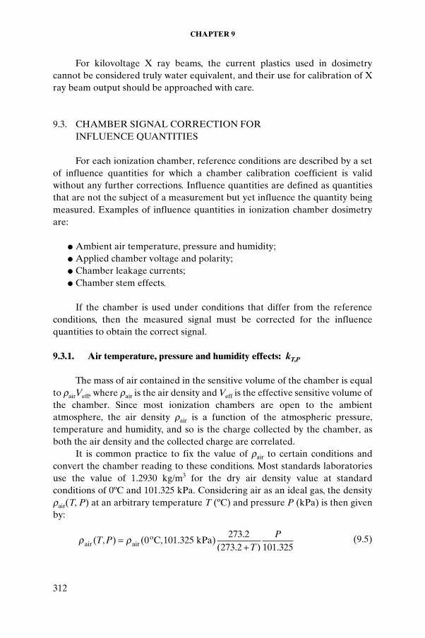
9.3.1. Air temperature, pressure and humidity effects: kT,P
The mass of air contained in the sensitive volume of the chamber is equal to rairVeff, where rair is the air density and Veff is the effective sensitive volume of the chamber. Since most ionization chambers are open to the ambient atmosphere, the air density rair is a function of the atmospheric pressure, temperature and humidity, and so is the charge collected by the chamber, as both the air density and the collected charge are correlated.
It is common practice to fix the value of rair to certain conditions and convert the chamber reading to these conditions. Most standards laboratories use the value of 1.2930 kg/m3 for the dry air density value at standard conditions of 0ºC and 101.325 kPa. Considering air as an ideal gas, the density rair(T, P) at an arbitrary temperature T (ºC) and pressure P (kPa) is then given by:
(9.5)r rair airoC kPa)( , ) ( , .
.( . ) .
T PT
P=+
0 101 325273 2
273 2 101 325
CALIBRATION OF PHOTON AND ELECTRON BEAMS
313
When calibrating an ionization chamber, the charge measured by the chamber depends on the air temperature, pressure and humidity, and therefore the calibration coefficient must be given for stated reference values of these parameters. At most standards laboratories the chamber signal is corrected to normal conditions of 20ºC (22ºC in North America) and 101.325 kPa, but no correction is applied for humidity. Instead, the relative humidity during calibration is controlled within the range from 45% to 55%, so that the calibration coefficient applies for relative humidities around 50%.
In the user’s beam, the correction factor for air temperature and air pressure kT,P is given as :
(9.6)
and is applied to convert the measured signal to the reference conditions used for the chamber calibration at the standards laboratory. Note that P and T (ºC) are chamber air pressure and temperature, respectively, at the time of measurement, while P0 and T0 (ºC) are the normal conditions used in the standards laboratory.
The temperature of the air in a chamber cavity should be taken as that of the phantom, which is not necessarily the same as the temperature of the surrounding air. For measurements in a water phantom the chamber waterproof sleeve should be vented to the atmosphere in order to obtain a rapid equilibrium between the ambient air and the air in the chamber cavity.
(Wair/e) and stopping powers that are used in dosimetry protocols are stated for dry air but are affected by chamber air humidity. This results in an overall humidity correction factor of 0.997 for a 60Co beam, correcting measurements at the 50% humidity level to those that would be obtained under dry air conditions and consisting of a 0.994 correction to the (Wair/e) dry air value of 33.97 J/C and a 1.003 correction to stopping powers.
9.3.2. Chamber polarity effects: polarity correction factor kpol
Under identical irradiation conditions the use of polarizing potentials of opposite polarity in an ionization chamber may yield different readings, a phenomenon that is referred to as the polarity effect. For most ionization chamber types, the effect is practically negligible at phantom depths exceeding the depth of dose maximum in megavoltage photon beams, but in the buildup region of megavoltage photon beams and in electron beams, notably at low energies, as well as in very low energy X ray beams, the effect may be significant.
kTT
P
PT P,( . )( . )
= ++
273 2273 2 0
0
CHAPTER 9
314
In electron beams the polarity effect is considered a charge balance effect that depends on the energy and angular distribution of the incident radiation, measurement depth in a phantom and field size. The polarity effect may actually change its sign with depth in a phantom.
When a chamber is used in a beam that produces a measurable polarity effect, the true reading is taken to be the mean of the absolute values of readings taken at the two polarities.
The polarity correction factor kpol is thus given by the following relationship:
(9.7)
where M+ and M– are the chamber signals obtained under identical irradiation conditions at positive and negative chamber polarities, respectively, and M is the signal obtained at the polarity used routinely (either positive or negative).
If the polarity effect for a particular chamber is larger than 3%, the chamber should not be used for absolute dose measurement.
Whenever the polarity has been changed, charge equilibrium and stable operating conditions should be re-established by preirradiating the chamber and waiting several minutes before the next measurement.
9.3.3. Chamber voltage effects: recombination correction factor ksat
The response of a given ionization chamber depends not only on the radiation dose, dose rate and chamber polarity but also on the voltage applied between the measuring and collecting electrodes of the chamber. The charges produced in the chamber by radiation may differ from the charges that are actually collected, and these discrepancies (charge losses or excess charges) occur as a result of constraints imposed by the physics of ion transport in the chamber sensitive volume and the chamber electrical design.
Charge losses in the chamber are caused by ion recombination; excess charges are caused by charge multiplication and electrical breakdown. Both charge recombination and charge multiplication are influenced by the potential applied to the ionization chamber.
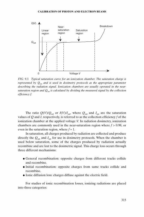
A plot of chamber response (i.e. current I or charge Q against the applied voltage V for a constant dose rate or dose, respectively) is called a saturation curve, first rising linearly with voltage at low voltages, then reaching a saturation at high voltages and eventually breaking down at even higher voltages. A sketch of a typical saturation curve is shown in Fig. 9.3.
kM M
Mpol =++ -
2
CALIBRATION OF PHOTON AND ELECTRON BEAMS
315
The ratio Q(V)/Qsat or I(V)/Isat, where Qsat and Isat are the saturation values of Q and I, respectively, is referred to as the collection efficiency f of the ionization chamber at the applied voltage V. In radiation dosimetry, ionization chambers are commonly used in the near-saturation region where f > 0.98, or even in the saturation region, where f ª 1.
In saturation, all charges produced by radiation are collected and produce directly the Qsat and Isat for use in dosimetry protocols. When the chamber is used below saturation, some of the charges produced by radiation actually recombine and are lost to the dosimetric signal. This charge loss occurs through three different mechanisms:
● General recombination: opposite charges from different tracks collide and recombine.
● Initial recombination: opposite charges from same tracks collide and recombine.
● Ionic diffusion loss: charges diffuse against the electric field.
For studies of ionic recombination losses, ionizing radiations are placed into three categories:
Qsat
Breakdown
0
Q(V)
Voltage V
Linear region
Near- saturation region
Saturation region
FIG. 9.3. Typical saturation curve for an ionization chamber. The saturation charge is represented by Qsat and is used in dosimetry protocols as the appropriate parameter describing the radiation signal. Ionization chambers are usually operated in the near-saturation region and Qsat is calculated by dividing the measured signal by the collection efficiency f.
CHAPTER 9
316
— Continuous radiation (e.g. cobalt beams and orthovoltage X rays); — Pulsed beams (e.g. non-scanned linac X ray beams and electrons); — Scanned pulsed beams (e.g. scanned linac beams).
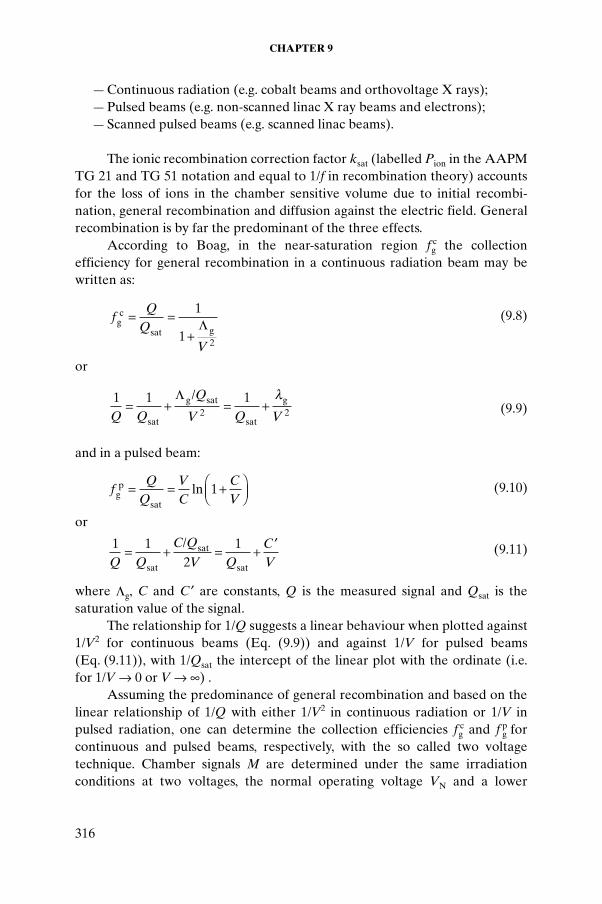
The ionic recombination correction factor ksat (labelled Pion in the AAPM TG 21 and TG 51 notation and equal to 1/f in recombination theory) accounts for the loss of ions in the chamber sensitive volume due to initial recombi-nation, general recombination and diffusion against the electric field. General recombination is by far the predominant of the three effects.
According to Boag, in the near-saturation region f cg the collection
efficiency for general recombination in a continuous radiation beam may be written as:
(9.8)
or
(9.9)
and in a pulsed beam:
(9.10)
or
(9.11)
where Lg, C and C ¢ are constants, Q is the measured signal and Qsat is the saturation value of the signal.
The relationship for 1/Q suggests a linear behaviour when plotted against 1/V2 for continuous beams (Eq. (9.9)) and against 1/V for pulsed beams (Eq. (9.11)), with 1/Qsat the intercept of the linear plot with the ordinate (i.e. for 1/V Æ 0 or V Æ •) .
Assuming the predominance of general recombination and based on the linear relationship of 1/Q with either 1/V2 in continuous radiation or 1/V in pulsed radiation, one can determine the collection efficiencies f c
g and f pg for
continuous and pulsed beams, respectively, with the so called two voltage technique. Chamber signals M are determined under the same irradiation conditions at two voltages, the normal operating voltage VN and a lower
fQ
Q
V
gc
sat g= =
+
1
1 2
L
1 1 12 2Q Q
Q
V Q V= + = +
sat
g sat
sat
g/L l
fQ
QVC
CVg
p
sat
= = +ÊËÁ
ˆ¯̃
ln 1
1 12
1Q Q
C Q
V QCV
= + = + ¢
sat
sat
sat
/
CALIBRATION OF PHOTON AND ELECTRON BEAMS
317
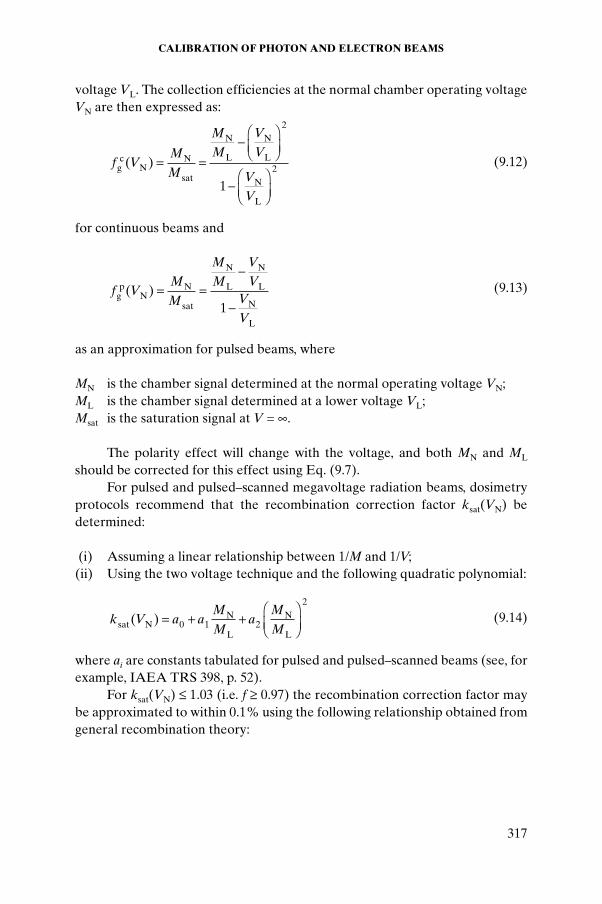
voltage VL. The collection efficiencies at the normal chamber operating voltage VN are then expressed as:
(9.12)
for continuous beams and
(9.13)
as an approximation for pulsed beams, where
MN is the chamber signal determined at the normal operating voltage VN;ML is the chamber signal determined at a lower voltage VL; Msat is the saturation signal at V = •.
The polarity effect will change with the voltage, and both MN and ML
should be corrected for this effect using Eq. (9.7).For pulsed and pulsed–scanned megavoltage radiation beams, dosimetry
protocols recommend that the recombination correction factor ksat(VN) be determined:
(i) Assuming a linear relationship between 1/M and 1/V;(ii) Using the two voltage technique and the following quadratic polynomial:
(9.14)
where ai are constants tabulated for pulsed and pulsed–scanned beams (see, for example, IAEA TRS 398, p. 52).
For ksat(VN) £ 1.03 (i.e. f ≥ 0.97) the recombination correction factor may be approximated to within 0.1% using the following relationship obtained from general recombination theory:
f VM
M
MM
VV
VV
gc
NN
sat
N
L
N
L
N
L
( ) = =-ÊËÁ
ˆ¯̃
-ÊËÁ
ˆ¯̃
2
2
1
f VM
M
MM
VV
VV
gp
NN
sat
N
L
N
L
N
L
( ) = =-
-1
k V a aM
Ma
M
Msat N 0N
L
N
L
( ) = + +ÊËÁ
ˆ¯̃1 2
2
CHAPTER 9
318
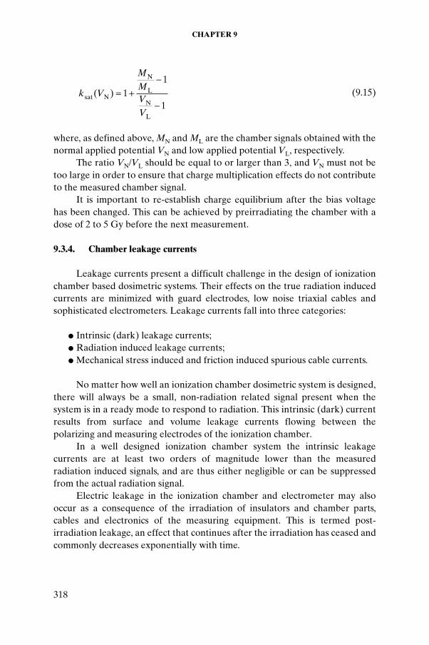
(9.15)
where, as defined above, MN and ML are the chamber signals obtained with the normal applied potential VN and low applied potential VL, respectively.
The ratio VN/VL should be equal to or larger than 3, and VN must not be too large in order to ensure that charge multiplication effects do not contribute to the measured chamber signal.
It is important to re-establish charge equilibrium after the bias voltage has been changed. This can be achieved by preirradiating the chamber with a dose of 2 to 5 Gy before the next measurement.
9.3.4. Chamber leakage currents
Leakage currents present a difficult challenge in the design of ionization chamber based dosimetric systems. Their effects on the true radiation induced currents are minimized with guard electrodes, low noise triaxial cables and sophisticated electrometers. Leakage currents fall into three categories:
● Intrinsic (dark) leakage currents;● Radiation induced leakage currents;● Mechanical stress induced and friction induced spurious cable currents.
No matter how well an ionization chamber dosimetric system is designed, there will always be a small, non-radiation related signal present when the system is in a ready mode to respond to radiation. This intrinsic (dark) current results from surface and volume leakage currents flowing between the polarizing and measuring electrodes of the ionization chamber.
In a well designed ionization chamber system the intrinsic leakage currents are at least two orders of magnitude lower than the measured radiation induced signals, and are thus either negligible or can be suppressed from the actual radiation signal.
Electric leakage in the ionization chamber and electrometer may also occur as a consequence of the irradiation of insulators and chamber parts, cables and electronics of the measuring equipment. This is termed post-irradiation leakage, an effect that continues after the irradiation has ceased and commonly decreases exponentially with time.
k V
MMVV
sat N
N
L
N
L
( ) = +-
-1
1
1
CALIBRATION OF PHOTON AND ELECTRON BEAMS
319
IEC 60731 recommends that within 5 s after the end of a 10 min irradiation the leakage current should have decreased to ±1.0% or less of the ionization current produced in the measuring volume during the irradiation (i.e. it will fall to the intrinsic leakage current level of the dosimetric system).
Another effect in insulators, which received considerable attention in the mid-1980s, is the charge accumulation in non-conductive plastic phantoms. This charge accumulation causes a very large electric field around the chamber directing the flow of electrons towards the chamber cavity, yielding an increased signal and an erroneous result for the collection efficiency.
Mechanical stress on cable insulators can also cause a leakage current, and for this reason unnecessary bending and twisting of the cables should be avoided.
9.3.5. Chamber stem effects
Irradiating the chamber stem often cannot be avoided, but it results in a different type of leakage current, which is generally referred to as the stem effect. Two mechanisms have been described by the IEC, namely stem scatter and stem leakage:
● Stem scatter arises from the effect of scattered radiation in the stem that reaches the chamber volume. This effect can be determined using a dummy stem, and the chamber is irradiated successively with and without the presence of the dummy stem; the ratio of the readings allows a correction factor for the effect to be determined.
● Stem leakage arises as a consequence of a direct irradiation of this chamber volume as well as of the insulators and cables in the chamber. The effect can be determined by irradiating a chamber twice with a narrow rectangular field, once in a parallel orientation and then perpen-dicularly to the chamber central axis. A correction factor can be derived as above.
9.4. DETERMINATION OF ABSORBED DOSE USING CALIBRATED IONIZATION CHAMBERS
For practical reasons, outputs of clinical photon and electron beams are usually measured with ionization chambers that have calibration coefficients traceable to a standards laboratory and are thus used as relative dosimeters. Before such a chamber is used in radiotherapy machine output calibration, the user must identify a dosimetry protocol (code of practice) appropriate for the
CHAPTER 9
320
given radiation beam. A dosimetry protocol provides the formalism and the data to relate a calibration of a chamber at a standards laboratory to the measurement of absorbed dose to water under reference conditions in the clinical beam. Two types of dosimetry protocol are available:
● Protocols based on air kerma in air calibration coefficients; ● Protocols based on absorbed dose to water calibration coefficients.
Most current megavoltage dosimetry protocols rely on chamber calibration coefficients determined in 60Co beams at standards laboratories. It is expected that the use of megavoltage beam calibration qualities (X rays and electrons), today available only in a few PSDLs, will become more widespread in the future.
Conceptually, both types of protocol are similar and are based on several steps in the process of determining the absorbed dose or dose rate from a charge or current measurement, respectively, with an ionization chamber.
The first step in the use of dosimetry protocols involves the determination of the chamber signal MQ through correction of the measured chamber charge or current for influence quantities known to affect the measured chamber signal, as discussed in Section 9.3. The subscript Q denotes the quality index of the beam being calibrated, as discussed in Section 9.8.
It should be noted that the formalisms presented here, based on a 60Co calibration coefficient, work well for megavoltage photon and electron beams. The calibration of superficial and orthovoltage X ray beams, on the other hand, relies on different principles and the chamber calibration coefficient should be obtained for the particular X ray beam quality that is being calibrated. The physics of kilovoltage dosimetry is discussed in more detail in Section 9.10.
9.4.1. Air kerma based protocols
Air kerma based protocols use the air kerma in air calibration coefficient NK,Co obtained for a local reference ionization chamber in a 60Co beam at a standards laboratory. Routine ionization chambers are then cross-calibrated with the reference ionization chamber in a local 60Co beam. Two steps are involved in an air kerma based protocol for the calibration of megavoltage photon and electron beams:
● The cavity air calibration coefficient ND,air is calculated from the NK,Co
calibration coefficient.
CALIBRATION OF PHOTON AND ELECTRON BEAMS
321
● Absorbed dose to water is determined using the Bragg–Gray relationship in conjunction with the chamber signal MQ and the cavity air calibration coefficient ND,air.
In a 60Co beam at a standards laboratory the mean absorbed dose to air in the cavity is determined from the total air kerma in air (Kair)air using the relationship:
Dair = (Kair)air(1 – g)kmkattkcel (9.16)
where
g is the fraction of the total transferred energy expended in radiative inter-actions on the slowing down of secondary electrons in air;
km is a correction factor for the non-air equivalence of the chamber wall and buildup cap needed for an air kerma in air measurement;
katt is a correction factor for photon attenuation and scatter in the chamber wall;kcel is a correction factor for the non-air equivalence of the central electrode
of the cylindrical ionization chamber.
The cavity air calibration coefficient ND,air is defined as:
ND,air = Dair/MQ (9.17)
where MQ is the chamber signal corrected for influence quantities. The air kerma in air calibration coefficient NK,Co is defined as:
NK,Co = (Kair)air/MQ (9.18)
If the electrometer device has its readout in nano-coulombs, both the cavity calibration coefficient and the air kerma in air calibration coefficient are given in units of cGy/nC.
By dividing the left and right hand sides of Eq. (9.16) by the corrected chamber signal in the calibration beam MQ, the cavity air calibration coefficient can be determined from the air kerma in air calibration coefficient, determined at the 60Co beam quality, using the relationship:
ND,air = NK,Co(1 – g)kmkattkcel (9.19)
The cavity air calibration coefficient is also directly related to the effective volume Veff of the chamber by:
CHAPTER 9
322
(9.20)
where
(Wair/e) is the average energy required to produce an ion pair in air;mair is the mass of air in the chamber cavity;rair is the air density at standard conditions of temperature and pressure; Veff is the effective air volume in the chamber collecting ions.
Equation (9.20) shows clearly that ND,air is a characteristic of the dosimetric device and depends only on the effective mass of air in the chamber cavity and does not depend on radiation quality as long as (Wair/e) is independent of the radiation quality. Hence the ND,air calibration coefficient determined at the 60Co beam quality at the standards laboratory is also valid at the user’s megavoltage beam quality Q.
If the effective chamber cavity volume Veff were accurately known, the ND,air calibration coefficient could in principle be determined using Eq. (9.20). This is the case for cavity ionization chambers used to establish the air kerma in air for cobalt units at standards laboratories (see Section 9.1.4). For typical ionization chambers used in the clinic, however, Veff is not known with sufficient accuracy and ND,air must be determined from the air kerma in air calibration coefficient NK,Co using Eq. (9.19).
The absorbed dose to air Dair,Q in the air cavity can be converted into absorbed dose to medium (e.g. water) Dw,Q by making use of the Bragg–Gray cavity relationship. With a known value of ND,air for a specific chamber, the fully corrected chamber signal MQ at a point in a phantom allows determination of the absorbed dose to water as follows:
Dw,Q = Dair,Q(sw,air)QpQ = MQND,air(sw,air)QpQ (9.21)
where
(sw,air)Q is the ratio of restricted collision stopping powers of water to air;pQ is a perturbation correction factor accounting for perturbations caused
by the chamber inserted into the medium, as discussed in detail in Section 9.7.
ND
M m
W
e V
W
eQD,air
air
air
air
air eff
air= = =1 1r

CALIBRATION OF PHOTON AND ELECTRON BEAMS
323
9.4.2. Absorbed dose to water based protocols
All dosimetry protocols aim at determination of the quantity absorbed dose to water. It is therefore logical to provide ionization chambers directly with a calibration coefficient in terms of this quantity, rather than in terms of the air kerma in air, if at all possible. Recent developments have provided support for a change in the quantity used at present to calibrate ionization chambers and provide calibration coefficients in terms of absorbed dose to water ND,w for use in radiotherapy beams. Many PSDLs now provide ND,w
calibrations in 60Co g ray beams and some laboratories have already extended these calibration procedures to high energy photon and electron beams.
The absorbed dose to water Dw,Q0 at the reference depth zref in water for a reference beam of quality Q0 and in the absence of the chamber is directly given by:
Dw,Q0 = MQ0ND,w,Q0 (9.22)
where MQ0 is the fully corrected chamber reading under the reference conditions used in the standards laboratory and ND,w,Q0 is the calibration coefficient in terms of the absorbed dose to water of the chamber obtained from the standards laboratory.
When a chamber is used in a beam of quality Q that differs from the quality Q0 that was used in its calibration, the absorbed dose to water is given by:
Dw,Q0 = MQ0ND,w,Q0kQ,Q0 (9.23)
where the factor kQ,Q0 corrects for the differences between the reference beam quality Q0 and the actual user quality Q.
The beam quality correction factor kQ,Q0 is defined as the ratio, at beam qualities Q and Q0, of the calibration coefficients in terms of absorbed dose to water of the ionization chamber:
(9.24)
Currently, the common reference quality Q0 used for the calibration of ionization chambers is the 60Co g radiation, and the symbol kQ,Co, abbreviated to kQ, is often used for the beam quality correction factor.
At some PSDLs high energy photon and electron beams are directly used for calibration purposes and the symbol kQ,Q0 is used in these cases, with Q0
kN
NQ QQ
Q,
,
,0
0
= D,w
D,w
CHAPTER 9
324
specifying the calibration beam. Ideally, the beam quality correction factor should be measured directly for each chamber at the same quality as the user’s beam. However, this is not achievable in most standards laboratories. Such measurements can be performed only in laboratories having access to the appropriate beam qualities; for this reason the technique is at present restricted to a few PSDLs around the world, as the procedure requires the availability of an energy independent dosimetry system, such as a calorimeter, operating at these beam qualities.
When no experimental data are available, or when it is difficult to measure kQ,Q0 directly for realistic clinical beams, the correction factors can, in many cases, be calculated theoretically. By comparing Eq. (9.24) with the ND,air
formalism given above, kQ,Q0 can be written as:
(9.25)
including the following ratios, at beam qualities Q and Q0:
● Spencer–Attix water to air restricted stopping power ratios sw,air; ● The perturbation factors pQ and pQ0 for departures from the ideal Bragg–
Gray detector conditions.
The calculations of kQ,Q0 are based on exactly the same data used in the calculations in the air kerma based approach, but the parameters are used as ratios, which have reduced uncertainties compared with individual values.
Most protocols provide a modified formalism for electron beams for use when a chamber is cross-calibrated (i.e. does not have a direct ND,w,Co
calibration coefficient). The details can be found in the IAEA TRS 398 and AAPM TG 51 protocols.
A still frequently used quantity is the exposure calibration coefficient NX, which is related to the air kerma in air calibration coefficient NK through the following relationship:
(9.26)
where g is the fraction of the energy loss in air expended in radiative interac-tions (the radiative fraction). For 60Co g rays in air g = 0.003, for superficial X rays in air g < 0.0002.
Typical units of NX and NK are R/nC and Gy/nC, respectively. A typical unit for both ND,air and ND,w is Gy/nC.
ks
s
p
pQ QQ
Q
Q
Q,
( )
( )00 0
= w,air
w,air
N NW
e gK Xair=
-1
1
CALIBRATION OF PHOTON AND ELECTRON BEAMS
325
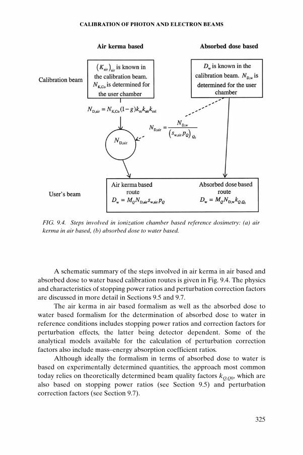
A schematic summary of the steps involved in air kerma in air based and absorbed dose to water based calibration routes is given in Fig. 9.4. The physics and characteristics of stopping power ratios and perturbation correction factors are discussed in more detail in Sections 9.5 and 9.7.
The air kerma in air based formalism as well as the absorbed dose to water based formalism for the determination of absorbed dose to water in reference conditions includes stopping power ratios and correction factors for perturbation effects, the latter being detector dependent. Some of the analytical models available for the calculation of perturbation correction factors also include mass–energy absorption coefficient ratios.
Although ideally the formalism in terms of absorbed dose to water is based on experimentally determined quantities, the approach most common today relies on theoretically determined beam quality factors kQ,Q0, which are also based on stopping power ratios (see Section 9.5) and perturbation correction factors (see Section 9.7).
FIG. 9.4. Steps involved in ionization chamber based reference dosimetry: (a) air kerma in air based, (b) absorbed dose to water based.
CHAPTER 9
326
9.5. STOPPING POWER RATIOS
The determination of absorbed dose in a medium using an ionization chamber is based on the Bragg–Gray principle relating the absorbed dose at a point in the medium (water) Dw to the mean absorbed dose in the detector (air) D–
air through a proportionality factor that classically has been identified as the ratio of the mass (collision) stopping powers water to air:
Dw = D–airsw,air (9.27)
The key Bragg–Gray assumption is that the electron fluence present in the detector is identical to that in the (undisturbed) medium at the point of interest in the water phantom. The gas filled ionization chamber in a high energy photon or electron beam behaves to a good approximation as a Bragg–Gray detector. Any deviations from perfect Bragg–Gray behaviour are accounted for by perturbation factors, which are discussed in detail in Section 9.7. The stopping power ratio applies to the electron spectrum at the point of interest in the undisturbed medium and is independent of the detector (except for the minor influence of the Spencer–Attix cut-off).
9.5.1. Stopping power ratios for electron beams
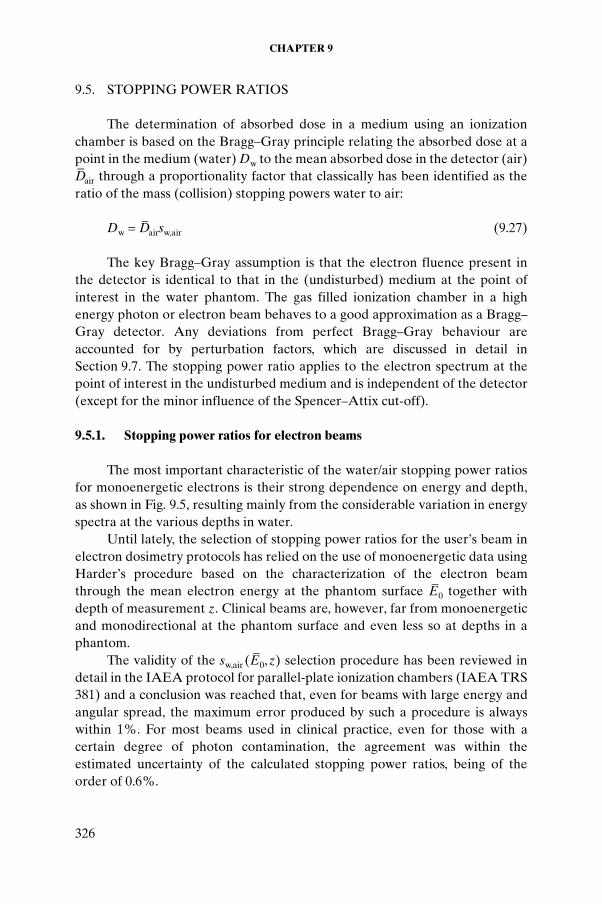
The most important characteristic of the water/air stopping power ratios for monoenergetic electrons is their strong dependence on energy and depth, as shown in Fig. 9.5, resulting mainly from the considerable variation in energy spectra at the various depths in water.
Until lately, the selection of stopping power ratios for the user’s beam in electron dosimetry protocols has relied on the use of monoenergetic data using Harder’s procedure based on the characterization of the electron beam through the mean electron energy at the phantom surface E
–0 together with
depth of measurement z. Clinical beams are, however, far from monoenergetic and monodirectional at the phantom surface and even less so at depths in a phantom.
The validity of the sw,air (E–
0,z) selection procedure has been reviewed in detail in the IAEA protocol for parallel-plate ionization chambers (IAEA TRS 381) and a conclusion was reached that, even for beams with large energy and angular spread, the maximum error produced by such a procedure is always within 1%. For most beams used in clinical practice, even for those with a certain degree of photon contamination, the agreement was within the estimated uncertainty of the calculated stopping power ratios, being of the order of 0.6%.
CALIBRATION OF PHOTON AND ELECTRON BEAMS
327
Stopping power ratios for realistic electron beams, obtained by simulating in detail the treatment head of some clinical accelerators, have become available and are used in the most recent dosimetry protocols based on standards of absorbed dose to water. However, it has been verified that no dramatic changes occur in electron beam dosimetry solely due to this improvement in the calculation of stopping power ratios.
9.5.2. Stopping power ratios for photon beams
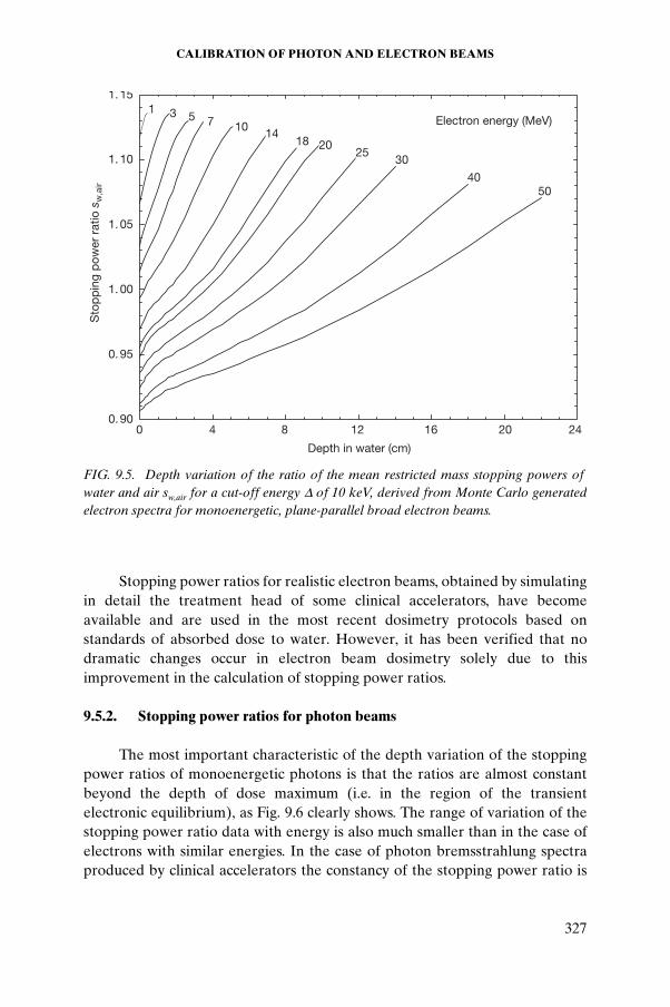
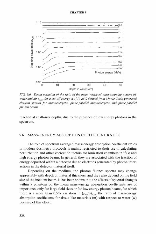
The most important characteristic of the depth variation of the stopping power ratios of monoenergetic photons is that the ratios are almost constant beyond the depth of dose maximum (i.e. in the region of the transient electronic equilibrium), as Fig. 9.6 clearly shows. The range of variation of the stopping power ratio data with energy is also much smaller than in the case of electrons with similar energies. In the case of photon bremsstrahlung spectra produced by clinical accelerators the constancy of the stopping power ratio is
0. 90
0. 95
1. 00
1. 05
1. 10
1. 15
5040
3025
2018141075
1 3
Depth in water (cm)
0 4 8 12 16 20 24
Sto
pp
ing
pow
er r
atio
sw
,air
Electron energy (MeV)
FIG. 9.5. Depth variation of the ratio of the mean restricted mass stopping powers offwater and air sw,air for a cut-off energy D of 10 keV, derived from Monte Carlo generated electron spectra for monoenergetic, plane-parallel broad electron beams.
CHAPTER 9
328
reached at shallower depths, due to the presence of low energy photons in the spectrum.
9.6. MASS–ENERGY ABSORPTION COEFFICIENT RATIOS
The role of spectrum averaged mass–energy absorption coefficient ratios in modern dosimetry protocols is mainly restricted to their use in calculating perturbation and other correction factors for ionization chambers in 60Co and high energy photon beams. In general, they are associated with the fraction of energy deposited within a detector due to electrons generated by photon inter-actions in the detector material itself.
Depending on the medium, the photon fluence spectra may change appreciably with depth or material thickness, and they also depend on the field size of the incident beam. It has been shown that the effects of spectral changes within a phantom on the mean mass–energy absorption coefficients are of importance only for large field sizes or for low energy photon beams, for which there is a more than 0.5% variation in (men/r)w,m, the ratio of mass–energy absorption coefficients, for tissue-like materials (m) with respect to water (w) because of this effect.
0.95
1.00
1.05
1.10
1.15
010203
05
07
010
015
020
030040
050
00.1
Depth in water (cm)
0 10 20 30 40 50
Sto
pp
ing
pow
er r
atio
sw
,air
Photon energy (MeV)
FIG. 9.6. Depth variation of the ratio of the mean restricted mass stopping powers offwater and air sw,air for a cut-off energy D of 10 keV, derived from Monte Carlo generated electron spectra for monoenergetic, plane-parallel monoenergetic and plane-parallel photon beams.
CALIBRATION OF PHOTON AND ELECTRON BEAMS
329
A consistent set of mass–energy absorption coefficient ratios for photon dosimetry used in most dosimetry protocols was given in the IAEA TRS 277 protocol. These data have not yet been superseded by any other new set of data.
9.7. PERTURBATION CORRECTION FACTORS
For a detector to behave as a Bragg–Gray cavity, the electron fluence in the sensitive medium of the detector must be identical to that at a specified point in the uniform medium. The only possible true Bragg–Gray detector would be an exceedingly small air bubble; all protocols for absolute dose deter-mination are, in fact, based on air filled ionization chambers.
For megavoltage photon radiation the Bragg–Gray conditions are adequately fulfilled for air cavities of the size encountered in practical ionization chambers (i.e. the ranges in air of the secondary electrons generated in megavoltage photon beams are much greater than the cavity dimensions). However, an ionization chamber does not consist only of an air cavity. There will always be a wall that, in general, is not perfectly medium equivalent. Often this wall is made of graphite, whereas the medium is water. Moreover, for cylindrical chambers there must be a central electrode, which is frequently made of aluminium, and there may be other materials around the chamber, such as a stem for cylindrical chambers and a back wall in the case of parallel-plate designs. All of these features can introduce deviations from perfect Bragg–Gray behaviour.
These deviations are generally dealt with by introducing one or more correction factor, often known as perturbation factors, into the expression for the absorbed dose (i.e. the factor pQ in Eq. (9.21)). This overall factor is often written as a product of four perturbation factors, each one accounting for a different effect, assumed to be independent of the others, as follows:
pQ = (pdis pwall pcel pcav)Q (9.28)
where
pdis is a factor that accounts for the effect of replacing a volume of water with the chamber cavity (cylindrical chambers);
pwall is a factor that corrects the response of the ionization chamber for the non-water equivalence of the chamber wall and any waterproofing material;
CHAPTER 9
330
pcel is a factor that corrects the response of the chamber for the effect of the central electrode during in-phantom measurements;
pcav is a factor that corrects the response of the ionization chamber for effects related to the air cavity, predominantly the in-scattering of electrons, which makes the electron fluence inside a cavity different from that in water in the absence of the cavity.
The word perturbation here means a perturbation by the detector of the electron fluence fmed(P) present at the point of interest P in a uniform medium where the relevant fluence in the detector, inevitably a mean value over a finite volume f̄det, is that which gives rise to the signal (i.e. the fluence in the air in the case of an ionization chamber).
Sections 9.7.1–9.7.4 deal with the four different sources of the Bragg–Gray cavity perturbation. The emphasis here is on the physics of these correction factors. A complete account of numerical values for the particular chamber and radiation quality of interest can be taken from the particular protocol being followed, and a concise summary of the protocol recommenda-tions is given in Section 9.9.
9.7.1. Displacement perturbation factor pdis and effective
point of measurement
An ionization chamber placed into a phantom will displace a certain volume of the phantom medium. Even if the chamber wall is medium equivalent, one still must consider the effect of the volume occupied by the air cavity. In general the dimensions of this volume are not negligible compared with any changes in the radiation field and hence in the dose distribution. For example, the dose may change by a few per cent within a distance equal to the diameter of the chamber. Clearly the chamber reading will be affected by this ‘missing’ medium. In simple terms one can expect that the reduced attenuation, in the case of photon beams, will result in a higher chamber reading compared with that in a very small ‘air bubble’ situated at the centre of the detector.
However, there is another effect: the missing material means that there is less scatter. This will counterbalance the first effect. The net result is still generally an increase in the signal that results in a correction factor known as the displacement perturbation factor, usually denoted by pdis, which will thus be less than unity.
The value of pdis will in general depend on both the radiation quality and the physical dimensions of the air cavity in the direction of the beam, as well as on the depth of measurement. In photon beams pdis will be practically constant beyond the depth of dose maximum, due to the exponential fall-off in dose;
CALIBRATION OF PHOTON AND ELECTRON BEAMS
331
however, in the buildup region it will vary in a complicated fashion with depth. For a Farmer chamber, which has an internal radius of 3 mm, the value is close to 0.988 in a 60Co beam.
The correction for displacement can be viewed in an alternative way. Instead of applying a factor to correct the chamber reading by assuming that the chamber is positioned so that its centre is at the depth of interest, a shift in the position of the chamber can be made. For a cylindrical chamber the electrons enter the wall at various depths, generally forward of its centre, and hence the electron fluence in the air cavity is representative of that existing at some point in the uniform medium shifted forward of the chamber centre. In fact, it was found that the readings of different chambers could be brought into coincidence with one another by performing shifts depending on the chamber dimensions. Thus the concept of the effective point of measurement Peff was developed.
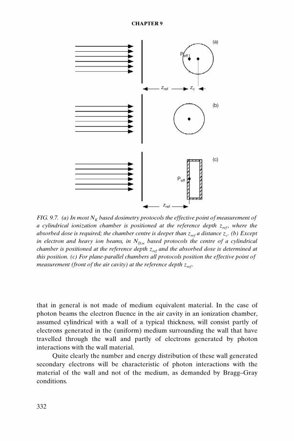
The newer absorbed dose to water based dosimetry protocols favour the pdis approach. However, air kerma in air based protocols use the Peff concept in preference to pdis. The IAEA TRS 277 protocol recommended a shift of 0.5r for 60Co g rays, increasing to 0.75r for all higher energy photon beams. More recent reviews of the experimental evidence on the magnitude of the shift led the IAEA to recommend a single value of 0.6r for all high energy photon beams (IAEA TRS 398), as indicated schematically by the parameter zc in Fig. 9.7(a).
In electron beams the use of pdis is impractical, since the depth dose curve is very irregular in shape, in contrast to the quasi-exponential decrease in photon beams at depths beyond the buildup region. Since pdis would vary rapidly and in an irregular way with depth in an electron beam, the Peff concept is universally employed in electron beams.
● For cylindrical chambers the recommended shift is 0.5r (IAEA TRS 277 and IAEA TRS 398).
● For parallel-plate chambers Peff is assumed to be situated in the centre of the inside face of the front wall, as illustrated in Fig. 9.7; this is logical since, in a well guarded chamber, it can be assumed that all the electrons entering the sensitive air volume do so through the front window.
9.7.2. Chamber wall perturbation factor pwall
Compliance with the Bragg–Gray conditions implies that the electron fluence in the sensitive volume of the detector is identical (strictly in magnitude, energy and angular distribution) to that present in the undisturbed medium at the position of interest. However, an ionization chamber has a wall
CHAPTER 9
332
that in general is not made of medium equivalent material. In the case of photon beams the electron fluence in the air cavity in an ionization chamber, assumed cylindrical with a wall of a typical thickness, will consist partly of electrons generated in the (uniform) medium surrounding the wall that have travelled through the wall and partly of electrons generated by photon interactions with the wall material.
Quite clearly the number and energy distribution of these wall generated secondary electrons will be characteristic of photon interactions with the material of the wall and not of the medium, as demanded by Bragg–Gray conditions.
(a)
(b)
(c)
zref
Peff
zref
Peff
zc
FIG. 9.7. (a) In most NK based dosimetry protocols the effective point of measurement offa cylindrical ionization chamber is positioned at the reference depth zref , where the absorbed dose is required; the chamber centre is deeper than zref a distance zc. (b) Except in electron and heavy ion beams, in ND,w based protocols the centre of a cylindrical chamber is positioned at the reference depth zref and the absorbed dose is determined at this position. (c) For plane-parallel chambers all protocols position the effective point offmeasurement (front of the air cavity) at the reference depth zref .
CALIBRATION OF PHOTON AND ELECTRON BEAMS
333
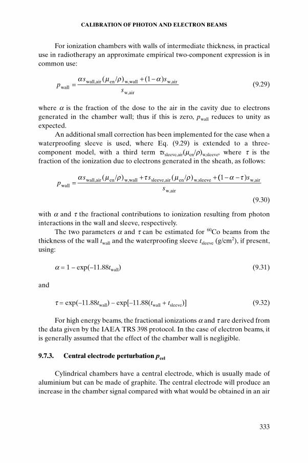
For ionization chambers with walls of intermediate thickness, in practical use in radiotherapy an approximate empirical two-component expression is in common use:
(9.29)
where a is the fraction of the dose to the air in the cavity due to electrons generated in the chamber wall; thus if this is zero, pwall reduces to unity as expected.
An additional small correction has been implemented for the case when a waterproofing sleeve is used, where Eq. (9.29) is extended to a three-component model, with a third term tssleeve,air(men/r)w,sleeve, where t is the fraction of the ionization due to electrons generated in the sheath, as follows:
(9.30)
with a and t the fractional contributions to ionization resulting from photon interactions in the wall and sleeve, respectively.
The two parameters a and t can be estimated for 60Co beams from the thickness of the wall twall and the waterproofing sleeve tsleeve (g/cm2), if present, using:
a = 1 – exp(–11.88twall) (9.31)
and
t = exp(–11.88twall) – exp[–11.88(twall + tsleeve)] (9.32)
For high energy beams, the fractional ionizations a and t are derived from the data given by the IAEA TRS 398 protocol. In the case of electron beams, it is generally assumed that the effect of the chamber wall is negligible.
9.7.3. Central electrode perturbation pcel
Cylindrical chambers have a central electrode, which is usually made of aluminium but can be made of graphite. The central electrode will produce an increase in the chamber signal compared with what would be obtained in an air
ps s
swallwall,air en w,wall w,air
w,air
/=
+ -a m r a( ) ( )1
ps s
wallwall,air en w,wall sleeve,air en w,sleeve/ /
=+ +a m r t m r( ) ( ) (( )1- -a t s
sw,air
w,air
CHAPTER 9
334
bubble, and a correction for the non-air equivalence of the electrode is in principle necessary; this is denoted by pcel.
The effect of a central electrode made of graphite has been shown to be practically negligible in photon beams but decreases with energy from 1.008 to 1.004 for a 1 mm diameter aluminium electrode.
In electron beams the effect is negligible for graphite, and never greater than 0.2% at any energy (5–20 MeV) or depth for a 1 mm diameter aluminium electrode.
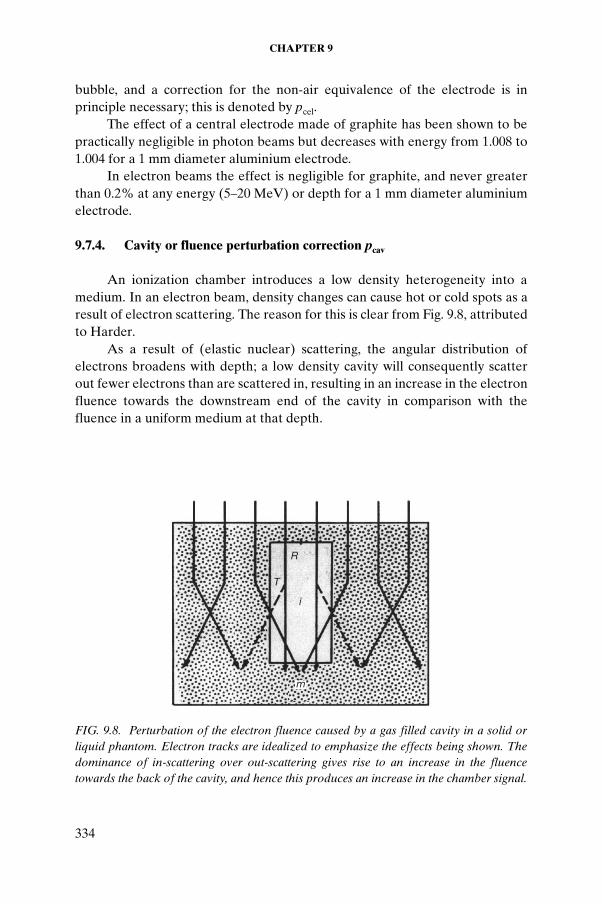
9.7.4. Cavity or fluence perturbation correction pcav
An ionization chamber introduces a low density heterogeneity into a medium. In an electron beam, density changes can cause hot or cold spots as a result of electron scattering. The reason for this is clear from Fig. 9.8, attributed to Harder.
As a result of (elastic nuclear) scattering, the angular distribution of electrons broadens with depth; a low density cavity will consequently scatter out fewer electrons than are scattered in, resulting in an increase in the electron fluence towards the downstream end of the cavity in comparison with the fluence in a uniform medium at that depth.
R
T
i
m
FIG. 9.8. Perturbation of the electron fluence caused by a gas filled cavity in a solid or liquid phantom. Electron tracks are idealized to emphasize the effects being shown. The dominance of in-scattering over out-scattering gives rise to an increase in the fluence towards the back of the cavity, and hence this produces an increase in the chamber signal.
CALIBRATION OF PHOTON AND ELECTRON BEAMS
335
All modern air kerma in air based dosimetry protocols include values of perturbation factors determined experimentally.
The magnitude of the in-scattering perturbation exceeds 3% for Farmer type chambers for Ez, the electron energy at depth z, below 8 MeV. This is one of the principal reasons why parallel-plate chambers are recommended in low energy electron beams. In a parallel-plate chamber the diameter of the air cavity (typically between 13 and 20 mm) is deliberately made very much greater than its thickness (the electrode spacing), which is 2 mm in almost all commercial designs. Thus most of the electrons enter the air cavity through the front face of the chamber and only a small fraction through the side walls.
Furthermore, well designed parallel-plate chambers have a relatively wide guard ring, 3 mm or more, which ensures that almost no electrons entering through the short side walls can contribute to the chamber signal. Conse-quently, in-scattering is virtually eliminated. The electron fluence in the sensitive volume of such a chamber is therefore that existing in the uniform medium at the depth of the inside face of the front window, which is the position of the effective point of measurement Peff. For cylindrical chambers this guarding capability is virtually absent and the electron fluence is signifi-cantly perturbed. For these chambers the cavity perturbation correction factor pcav is given by:
pcav (E–0, r) = 1 – 0.02155r exp(–0.1224 E–z) (9.33)
where r is the cavity inner radius in millimetres and E–z is the mean electron energy at depth z as obtained from the Harder relationship (see Eq. (9.36)).
In photon beams there is generally charged particle equilibrium (CPE) (or a very good approximation to it), and therefore no change in either the energy or the angular distribution of the secondary electrons with position in the irradiated medium. The electron fluence perturbation effect is therefore negligible in photon beams. However, in the buildup region in photon beams, where there is no CPE, significant perturbation effects have been demon-strated.
9.8. BEAM QUALITY SPECIFICATION
The signal (current or charge) that is produced by an ionization chamber and measured by an electrometer must be multiplied by factors correcting for influence quantities (see Section 9.3) and the various dosimetric physical quantities described in the previous sections to yield the absorbed dose to water at a reference point in water, the quantity in terms of which radiotherapy
CHAPTER 9
336
machine output is specified. Some of these quantities depend upon photon or electron beam energy, thus the beam quality needs to be specified for dosimetric calculations.
The most logical means to characterize the quality of a clinical radiation beam is to state its spectral distribution. However, since beam spectra are difficult to measure directly and cumbersome to determine in an absolute sense with Monte Carlo techniques, other, more practical, approaches to beam quality specification have been developed. These approaches are specific to three distinct ionizing radiation beam categories:
● Kilovoltage (superficial and orthovoltage) X ray beams;● Megavoltage X ray beams;● Megavoltage electron beams.
9.8.1. Beam quality specification for kilovoltage photon beams
For low energy photon beams the quality of the beam is most conven-iently expressed in terms of the half-value layer (HVL) of the beam, with HVL representing the thickness of an attenuator that decreases the measured air kerma rate in air to half of its original value.
To minimize the effects of radiation scattered in the attenuator the HVL must be measured under ‘good geometry’ conditions that imply the use of:
● A narrow beam geometry to minimize scattering from the attenuator;● A reasonable distance between the attenuator and the measuring device
(ionization chamber) to minimize the number of scattered photons reaching the detector;
● An ionization chamber with air equivalent walls and with a flat photon energy response for the spectrum of radiations comprising the beam.
For superficial X ray beams (10–100 kVp) HVLs are usually given in millimetres of pure aluminium (typical HVLs from 0.01 to 10 mm of aluminium), while for orthovoltage X ray beams (above 100 kVp) HVLs are usually given in millimetres of pure copper (typical HVLs from 0.5 to 4 mm of copper).
The specification of beam quality in terms of the HVL is really a very crude beam specification, since it tells little about the energy distribution of the photons present in the beam. However, the beam specification through the HVL provides a general idea of the effective energy of the photon beam, which may be used to assess the beam penetration into tissue and to determine the appropriate values of the quantities used in dosimetry protocols.
CALIBRATION OF PHOTON AND ELECTRON BEAMS
337
Since two beams with widely differing potentials can have similar HVLs, due to the marked effect of different filtrations, it is customary to state, in addition to the HVL, the X ray potential and total filtration used in generating a given X ray beam.
Often low energy X ray beams are also characterized by stating their homogeneity coefficient k, which is defined as the ratio between the first and second HVL (i.e. = HVL1/HVL2). For heterogeneous low energy X ray beams HVL2 > HVL1, resulting in k < 1; for monochromatic beams, on the other hand, HVL2 = HVL1 and k = 1.
Another quantity that is often used in beam quality specification is the equivalent or effective photon energy, defined as the quantum energy of a monoenergetic beam having an HVL equal to HVL1 of the heterogeneous beam being specified.
9.8.2. Beam quality specification for megavoltage photon beams
In the megavoltage photon energy range, HVLs vary little with photon energy, making HVLs unsuitable for beam quality specification. Other indices were therefore developed, relating to the energy of the electron beam as it strikes the target (nominal accelerating potential (NAP)) and to radiation beam attenuation as the beam penetrates into water or tissue. Older radiation protocols were based on the NAP, while the recent ones are based on quantities that are related to beam penetration into water, such as the tissue–phantom ratio (TPR) or percentage depth dose (PDD).
A considerable improvement was made to air kerma in air based dosimetry protocols when stopping power ratios and mass–energy absorption coefficient ratios were correlated with clinically measured ionization ratios, such as the TPR20,10, rather than with NAPs.
The parameter TPR20,10 is defined as the ratio of doses on the beam central axis at depths of 20 cm and 10 cm in water obtained with a constant source to detector distance of 100 cm and a field size of 10 × 10 cm2 at the position of the detector. The TPR20,10 is a measure of the effective attenuation coefficient describing the approximately exponential decrease of a photon depth dose curve beyond the depth of maximum dose zmax, and, more impor-tantly, it is independent of electron contamination of the incident photon beam.
The TPR20,10 can be related to the measured PDD20,10 using the following relationship:
TPR20,10 = 1.2661PDD20,10 – 0.0595 (9.34)
CHAPTER 9
338
where PDD20,10 is the ratio of PDDs at depths of 20 cm and 10 cm for a field of 10 × 10 cm2 defined at the water phantom surface with an SSD of 100 cm. This empirical relationship was obtained from a sample of almost 700 linacs.
Other beam quality indices have been proposed for megavoltage photon dosimetry; they are, in most cases, related to the depth of maximum dose zmax, making them susceptible to the electron contamination of the beam at this depth in a water phantom.
Based on PDD distributions, a widely disseminated recommendation for specifying the quality of high energy photon beams was made in British Journal of Radiology Supplement 17, which defined a parameter d80 as the depth of the 80% depth dose for a 10 × 10 cm2 field at an SSD of 100 cm.
British Journal of Radiology Supplement 17 clearly points out that electron contamination of the photon beam should be considered a practical shortcoming of the d80 method. The use of TPR20,10 as a photon beam quality index has also been endorsed by the recent British Journal of RadiologySupplement 25, although other beam quality specifiers, such as the PDD(10), are also considered.
The parameter PDD(10), the PDD at 10 cm depth in water, determined under the same conditions of field size and SSD as the parameter d80, has in principle the same limitation with regard to the effect of electron contami-nation as d80. A recommendation has been made that a 1 mm thin lead foil be used in measurements to remove the unknown electron contamination from the reading at zmax and to replace it by a known amount of electron contami-nation to arrive at the PDD with the presence of the lead foil, PDD(10)Pb. A correction formula is provided to convert PDD(10)Pb into PDD(10)x, the PDD at a depth of 10 cm in water in a pure photon beam excluding the electron contamination at zmax.
The advantages and limitations of the different photon beam quality indices have been discussed at great lengths in the scientific literature. The general conclusion is that there is no unique beam quality index that works satisfactorily in all possible conditions for the entire energy range of megavoltage photon energies used in radiotherapy and for all possible linacs used in hospitals and standards laboratories.
Most recent dosimetry protocols based on in-water calibrations of ionization chambers use the TPR20,10 as the beam quality index (IPEM, IAEA TRS 398, etc.); the AAPM TG 51 protocol, however, uses the PDD(10)x. For a user in a hospital or clinic there is no advantage of one specifier (index) over the other, as both lead to the same dose conversion factors and hence yield the same dose to water in the user’s beam. However, the choice of the beam quality index should not be governed by user preference but should follow the
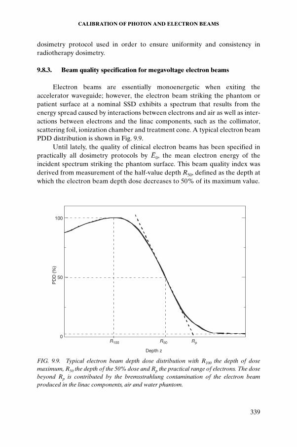
CALIBRATION OF PHOTON AND ELECTRON BEAMS
339
dosimetry protocol used in order to ensure uniformity and consistency in radiotherapy dosimetry.
9.8.3. Beam quality specification for megavoltage electron beams
Electron beams are essentially monoenergetic when exiting the accelerator waveguide; however, the electron beam striking the phantom or patient surface at a nominal SSD exhibits a spectrum that results from the energy spread caused by interactions between electrons and air as well as inter-actions between electrons and the linac components, such as the collimator, scattering foil, ionization chamber and treatment cone. A typical electron beam PDD distribution is shown in Fig. 9.9.
Until lately, the quality of clinical electron beams has been specified in practically all dosimetry protocols by E–0, the mean electron energy of the incident spectrum striking the phantom surface. This beam quality index was derived from measurement of the half-value depth R50, defined as the depth at which the electron beam depth dose decreases to 50% of its maximum value.
R100 R50 Rp
Depth z
100
50
0
PD
D (%
)
FIG. 9.9. Typical electron beam depth dose distribution with R100 the depth of dose maximum, R50 the depth of the 50% dose and Rp the practical range of electrons. The dose beyond Rp is contributed by the bremsstrahlung contamination of the electron beam produced in the linac components, air and water phantom.
CHAPTER 9
340
The empirical relationship between E–0 and R50 is:
E–
0 = CR50 (9.35)
where
C is a constant (2.33 MeV/cm);R50 is the half-value depth in centimetres.
Strictly speaking, Eq. (9.35) is valid only for large field sizes (broad beams), for electron energies between 5 and 30 MeV, and for R50 determined from depth dose distributions measured in water with a constant source to chamber distance. The criterion for a broad beam is satisfied when the depth dose distribution is independent of field size, and this is achieved for field sizes exceeding 12 × 12 cm2 for electron beam energies below 15 MeV and at least 20 × 20 cm2 for energies above 15 MeV.
The mean energy at depth z in a phantom, E–
z, is also a quantity of general use in electron beam dosimetry. An empirical relationship, originally proposed for the most probable energy of an electron spectrum at a depth z in a water phantom, has been recommended by many electron dosimetry protocols to determine E
–z according to:
E–
z = E–
0(1 – z/Rp) (9.36)
where Rp is the practical range of the electron beam defined as the depth where the tangent at the steepest point (the inflection point) on the almost straight descending portion of the depth dose curve meets the extrapolated brems-strahlung background.
Equation (9.36) is only an acceptable approximation of the mean energy at depth in water for electron beams with incident energies of less than 10 MeV or for small depths at higher energies. In other situations the mean electron energy E
–z is obtained from tabulated data of E
–z/E
–0 versus the scaled depth z/Rp
(IAEA TRS 277). Much of the available data for electron dosimetry that were originally
given in terms of E–
z determined from Eq. (9.36) have been recast to Monte Carlo determined E
–z in recent dosimetry protocols.
When R50 and Rp have been determined in a plastic phantom rather than in water, the electron ranges in plastic Rpl should be converted into ranges in water as follows:
Rwater = RplCpl (9.37)
CALIBRATION OF PHOTON AND ELECTRON BEAMS
341
where Cpl is a material dependent scaling factor that was defined by the IAEA TRS 381 protocol as the ratio of average electron penetrations in water and plastic and is equivalent to the effective density of the AAPM TG 25 dosimetry protocol.
PDD distributions for clinical electron beams are most commonly determined from ionization measurements carried out in water or water equivalent phantoms with diodes or ionization chambers.
● Percentage depth ionization curves measured with a diode represent the PDD curve, since the mass collision stopping power ratios silicon to water are essentially constant with depth in a phantom (i.e. with electron beam energy).
● Percentage depth ionization curves measured with an ionization chamber, on the other hand, must be corrected for gradient effects as well as for variations in mass collision stopping power ratios water to air with electron energy when determining the PDDs from ionization measure-ments.
R50 may be determined from I50, the 50% value on the percentage depth ionization curve measured with an ionization chamber in water, as follows:
R50 = 1.029I50 (cm) – 0.06 cm (for 2 cm £ I50 £ 10 cm) (9.38)
and
R50 = 1.059I50 (cm) – 0.37 cm (for I50 > 10 cm) (9.39)
E–
0 and E–
z are determined from the measured R50 and Rp, respectively, and their use in electron beam dosimetry should be considered an approxi-mation that facilitates the selection of dosimetric quantities and correction coefficients, rather than being an accurate statement on the energy parameters of clinical electron beams.
To avoid potential misunderstandings of the meaning of the energy based relationships, the recent dosimetry protocols use R50 directly as a beam quality index for selecting stopping power ratios and reference depths. This parallels the long standing practice in photon dosimetry in which beam qualities are expressed in terms of the penetration of the beam into a water phantom.
The choice of R50 as the beam quality index is a change from the previous practice of specifying beam quality in terms of the mean energy at the phantom surface. Since E
–0 is normally derived from R50, this change in beam quality
index is merely a simplification that avoids the need for a conversion to energy.
CHAPTER 9
342
By choosing a specific reference depth zref for the calibration in water the stopping power ratio water to air has been shown to depend only on R50.
The recent dosimetry protocols based on in-water calibration by the IAEA (TRS 398) and the AAPM (TG 51) have endorsed this approach, and all data are expressed in terms of R50. The reference depth zref for electron beam calibration in water is expressed in terms of R50 as follows:
zref = 0.6R50 (cm) – 0.1 cm (9.40)
The reference depth in water is close to the depth of dose maximum zmax
for beams with R50 < 4 cm (E–
0 < 10 MeV); however, for beams with R50 ≥ 4 cm, zref is deeper than zmax. This choice of reference depth may be less convenient than that recommended in previous protocols, since for a given linac no two reference beams will have the same reference depth. However, the new reference depth defined by Eq. (9.40) has been shown to reduce significantly machine to machine variations in chamber calibration coefficients, and the gained accuracy justifies its use.
9.9. CALIBRATION OF MEGAVOLTAGE PHOTON AND ELECTRON BEAMS: PRACTICAL ASPECTS
This section summarizes the practical aspects of the recommendations made in air kerma in air based and absorbed dose to water based codes of practice or protocols for the calibration of megavoltage photon and electron beams. For numerical values on the various correction and conversion factors we refer to the IAEA TRS 277 or the IAEA TRS 398 protocols. For background on the physical meaning of the factors we refer to the previous sections.
9.9.1. Calibration of megavoltage photon beams based on the air kerma
in air calibration coefficient NK,Co
A cylindrical ionization chamber is used at a given depth z in a water phantom (typically z is 5 or 10 cm). The calibration is based on an air kerma in air calibration coefficient NK,Co obtained in a 60Co beam at a standards laboratory.
Beam quality is specified with a ratio of TPRs, TPR20 at depths of 20 cm and 10 cm in water or with the PDD at a depth of 10 cm in water with electron contamination removed, PDD(10)x, as discussed in Section 9.8.2.
CALIBRATION OF PHOTON AND ELECTRON BEAMS
343
The Bragg–Gray or Spencer–Attix cavity theory is used to determine the absorbed dose Dw(z) or dose rate at the point of interest at depth z in the water phantom from the measured signal MQ (charge or current) as follows:
Dw(z) = MQND,airsw,airpwallpcel (9.41)
where
MQ is the chamber current or charge corrected for influence quantities and measured at beam quality Q;
ND,air is related to NK through Eq. (9.19); sw,air is the restricted stopping power ratio between water and air averaged
over the electron slowing down spectrum resulting from the photon spectrum;
pwall is the wall correction factor that accounts for the non-equivalence of the medium and wall;
pcel is the central electrode correction factor that accounts for scatter and absorption of radiation on the central electrode (the factor was ignored in the AAPM TG 21 protocol but introduced in the IAEA TRS 277 and subsequent IAEA dosimetry protocols).
In the IAEA air kerma in air based protocols, the displacement effect resulting from the insertion of an air cavity into a phantom is accounted for by defining an effective point of measurement while the cavity perturbation effect is negligible. For cylindrical chambers in high energy photon beams the effective point of measurement is located 0.6r upstream of the chamber centre, r being the cavity inner radius.
For the purpose of absorbed dose measurements, in the absorbed dose to water based protocols the point of measurement is defined as the centre of the chamber and the displacement effects are accounted for by the introduction of the ‘gradient correction factor’ equivalent to pdis.
The cavity fluence perturbation correction factor pcav is unity in high energy photon beams.
9.9.2. Calibration of megavoltage photon beams based on the dose to water calibration coefficient ND,w,Co
A cylindrical ionization chamber is used at a given depth z in a water phantom (typically z is 10 cm). The calibration is based on a dose to water chamber calibration coefficient ND,w,Co obtained from a standards laboratory
CHAPTER 9
344
with the chamber irradiated with a 60Co beam at a reference depth zref in a water phantom.
The absorbed dose to water Dw,Co at a given depth in a phantom in a cobalt beam in the absence of the ionization chamber is given by:
Dw,Co = McoND,w,Co (9.42)
where Mco is the chamber signal (charge or current) corrected for influence quantities, as discussed in Section 9.3.
When the ionization chamber is used in a beam quality Q different from the 60Co used in its calibration, the absorbed dose to water is given by:
Dw,Q = MQND,w,CokQ,Co (9.43)
where the correction factor kQ,Co corrects for the effects of the difference between the reference 60Co beam quality (Co) and the actual user beam quality Q, and the chamber signal MQ has been corrected to the reference values of influence quantities, other than beam quality, for which the calibration coefficient is valid.
The beam quality Q of megavoltage photon beams is specified, as discussed in Section 9.8.2, either with a ratio of TPRs (TPR20,10(Q)) or with the PDD (PDD(10, 10 × 10, SSD, Q)x.
The IAEA TRS 398 dosimetry protocol recommends the use of the ratio of TPRs, while the AAPM TG 51 protocol recommends the use of PDDx, for megavoltage photon beam quality specification. Despite considerable polemics on the merits of each of the two approaches, in practice they both give essentially the same results for the megavoltage photon beams currently used in clinical practice.
The beam quality correction factor kQ,Co is defined as the ratio, at the beam qualities Q and Co, of the calibration coefficients in terms of the absorbed dose to water of the ionization chamber:
(9.44)
Ideally, the beam quality correction factors should be measured directly for each ionization chamber at the same quality as the user’s beam. In practice, this is generally not possible, so the factors are calculated theoretically assuming the validity of Bragg–Gray cavity theory and using the ND,air concept (see Section 9.4).
kN
NQQ
,CoD,w,
D,w,Co
=
CALIBRATION OF PHOTON AND ELECTRON BEAMS
345
9.9.3. Calibration of megavoltage electron beams based on the air kerma in air calibration coefficient NK,Co
For electron beams with energies equal to or above 10 MeV a cylindrical or a parallel-plate ionization chamber is used at a reference depth in a water phantom (usually close to zmax). For electron energies below 10 MeV a parallel-plate ionization chamber must be used. The calibration is based on air kerma in air calibration coefficient NK obtained in a 60Co beam at the standards laboratory, but for parallel-plate chambers a cross-calibration against a cylindrical chamber allows a direct determination of the ND,air coefficient.
E–
0, the mean electron energy on a phantom surface, is used for specifying the electron beam quality (Eq. (9.35)).
The Spencer–Attix cavity relationship is used to determine the absorbed dose at the reference point in a water phantom as follows:
Dw(z) = MQND,airsw,airpcavpcel (9.45)
where
MQ is the corrected measured chamber current or charge.ND,air is related to NK through Eq. (9.19).sw,air is the restricted stopping power ratio between water and air.pcav is the cavity fluence perturbation correction factor accounting for the in-
scattering effect as discussed in Section 9.7. It is unity for well guarded parallel-plate chambers and is given by Eq. (9.33) for Farmer type cylindrical chambers.
pcel is the central electrode correction factor that accounts for scatter and absorption of radiation on the central electrode of a cylindrical chamber. The factor was ignored in the AAPM TG 21 protocol but was taken into account in the IAEA TRS 277 and subsequent IAEA protocols, as well as in the AAPM TG 51 protocol.
For parallel-plate chambers the effective point of measurement is located on the inner surface of the window at its centre, and no gradient correction is required.
For cylindrical ionization chambers, on the other hand, the effective point of measurement is located 0.5r upstream from the chamber centre. In the AAPM protocols, in the latter case, the point of measurement is defined as the centre of the chamber and the gradient effects are to be accounted for by the introduction of the gradient or displacement correction factor pdis.
CHAPTER 9
346
The wall correction factor pwall is considered unity in electron beam dosimetry.
9.9.4. Calibration of high energy electron beams based on the dose to water calibration coefficient ND,w,Co
The output calibration is based on a dose to water chamber calibration coefficient ND,w,Co obtained from a standards laboratory with the chamber irradiated in a reference beam of quality Q0. This reference quality is most commonly a 60Co g ray beam (ND,w,Co), but may also be an electron beam.
Parallel-plate ionization chambers are recommended for all electron beam qualities and must be used for electron beams of energies below 10 MeV. At electron energies equal or above 10 MeV the use of cylindrical chambers is allowed.
The reference point for parallel-plate chambers is taken to be on the inner surface of the entrance window, at the centre of the window.
Water is recommended as the reference medium. The water phantom should extend to at least 5 cm beyond all four sides of the largest field size employed. For electron energies below 10 MeV a plastic phantom may be used, but all depths must be scaled appropriately.
The beam quality index for electron beams is R50, the half-value depth in water, measured with a field size of at least 10 × 10 cm2 for R50 £ 7 g/cm2 and at least 20 × 20 cm2 for R50 > 7 g/cm2. The preferred choice of detector for the measurement of R50 is a well guarded parallel-plate ionization chamber, the preferred choice of phantom medium is water.
Output calibration is carried out in a water phantom at a reference depth zref with a field of 10 × 10 cm2. The reference depth is given by:
zref = 0.6R50 – 0.1 g/cm2 (9.46)
with R50 given in g/cm2. This depth is close to the depth of dose maximum zmax
at beam qualities R50 < 4 g/cm2 (E0 £ 10 MeV); at higher beam energies it is deeper than zmax.
The absorbed dose to water at the reference depth zref in an electron beam of quality Q, in the absence of the chamber, is given by:
Dw,Q = MQND,w,CokQ,Co (9.47)
where
MQ is the chamber signal corrected for influence quantities;
CALIBRATION OF PHOTON AND ELECTRON BEAMS
347
ND,w,Co is the calibration coefficient in terms of absorbed dose to water for the chamber irradiated in a 60Co beam at a standards laboratory;
kQ,Co is a chamber correction factor for differences between the reference beam quality (Co) and the actual electron beam quality Q.
Calculated values of kQ,Co against R50 are available in dosimetry protocol documents for a wide variety of parallel-plate and cylindrical ionization chambers. They are tabulated directly in the IAEA TRS 398 protocol or determined as a product of conversion and correction factors termed kecal, k ¢R50
and Pgr in the AAPM TG 51 protocol.
9.10. KILOVOLTAGE DOSIMETRY
During the past 30 years there has been a great deal of development in the dosimetry of high energy (i.e. megavoltage photon and electron) beams. The dosimetry of kilovoltage X ray beams (low and medium energy or ortho-voltage X ray beams), on the other hand, remained more or less static in that period until the late 1980s. Despite this, kilovoltage beams are still in widespread use for the treatment of superficial lesions.
The IAEA TRS 277 protocol devoted a separate, detailed section to kilovoltage X rays, setting out a new air kerma in air based formalism, and this has recently been followed by several national dosimetry protocols on kilovoltage X ray dosimetry. Note that the second edition of the IAEA TRS 277 protocol provided substantial changes to the numerical data given in the original publication of 1987.
9.10.1. Specific features of kilovoltage beams
When kilovoltage X rays interact with a medium, the secondary electrons have extremely short ranges due to their low initial energy coupled with the rapid increase of the collision stopping power at subrelativistic energies. This results in several important differences between kilovoltage and megavoltage beams as far as radiation dosimetry is concerned:
● The Bragg–Gray principle can no longer be applied to such beam qualities (i.e. the electron fluence in the air cavity of the ionization chamber is not exclusively determined by electron interactions in the surrounding medium);
● Owing to the short electron ranges, absorbed dose can be equated to the collision kerma to a very good approximation;
CHAPTER 9
348
● Radiative losses can be ignored in low atomic number materials, so that absorbed dose and kerma are essentially equivalent.
An ionization chamber calibration coefficient in kilovoltage X rays is determined with reference to a free air ionization chamber at a set of kilovoltage radiation qualities, in contrast to a single air kerma in air calibration coefficient at 60Co for megavoltage beams. Since the wall thickness of a typical cylindrical ionization chamber is larger than the range of secondary electrons created in it, CPE is established in the wall without a buildup cap. For this reason, and since the chamber calibration coefficient is given in terms of air kerma in air, the calibrated chamber acts as a kerma detector even when used in a phantom.
The amount of photon scatter in a tissue equivalent phantom at kilovoltage energies is much larger than in high energy photon beams. This fact makes ratios of mass–energy absorption coefficients and, to a lesser extent, other, detector related dosimetric quantities depth and field size dependent.
Kilovoltage beam quality is specified differently than megavoltage beam quality. As discussed in Section 9.8, for kilovoltage beams the beam quality is specified in terms of the HVL, generally expressed in millimetres of aluminium or, at the top end of the energy range, in millimetres of copper.
It should be noted that beams with widely differing tube potentials may have similar HVLs, due to the marked effect of different filtrations. Thus the user determines the HVL of the beams of interest and then chooses NK values for the calibrated chamber for the beam using the calibration curve supplied by the standards laboratory.
9.10.2. Air kerma based in-phantom calibration method
(medium energies)
For medium energy X ray beams, typically above 100 kV, various dosimetry protocols recommend that the dose be determined at a depth in a water phantom, similarly to recommendations for megavoltage beam qualities. The various dosimetry protocols differ, however, in their specification of the reference depth.
The IAEA TRS 277 protocol followed early recommendations of the ICRU and specifies a depth of 5 cm in water.
The UK protocol (IPEMB, 1996) chose instead a depth of 2 cm in water for the reference depth, considering this to be much more representative of clinical practice; this has also been adopted in several other recent protocols.
The formalism for the determination of the absorbed dose to water is:
CALIBRATION OF PHOTON AND ELECTRON BEAMS
349
Dw,Q = MQNK,Q[(men/r)w,air]Q pQ (9.48)
where, for the HVL of the user’s beam (Q):
MQ is the instrument reading corrected for influence quantities (see Section 9.3);
NK,Q is the air kerma in air chamber calibration coefficient for beam quality Q;
(men/r)w,air is the mass–energy absorption coefficient ratio water to air for the photon spectrum at the depth of measurement in water and for the field size of the user’s beam;
pQ is an overall perturbation correction factor, which is not to be confused with the pQ factor of Eq. (9.28) and which consists of multi-plicative components of a different nature than those involved in Eq. (9.28).
For a detailed description of these components please refer to, for example, the AAPM TG 61 protocol.
There is only a weak dependence on field size or depth in the values of (men/r)w,air in general and in the pQ values for Farmer type chambers. Cylindrical chambers of the Farmer type are commonly used at this energy range. All recent kilovoltage dosimetry protocols agree to within about 1.5% in the deter-mination of the absorbed dose to water at 2 cm depth in a water phantom.
9.10.3. Air kerma based backscatter method (low and medium
photon energies)
Clinically, for these beams, the dose is most often prescribed for the skin surface (strictly just below the surface, where CPE is established). This has led to the most important and widely used method of determining the absorbed dose. The principle is straightforward. A chamber is positioned free in air (i.e. with no phantom involved) at a position corresponding to the centre of the field on the patient’s skin surface. The reading of the (calibrated) chamber yields the air kerma in air (Kair)air. This is then converted into dose to water at the surface of a phantom at the field size of interest. The energy or quality range for this method differs slightly from protocol to protocol, but all of the protocols denote it by the term low energy; in the IAEA TRS 277 protocol this range is 10–160 kV.
The theoretical route is as follows:
CHAPTER 9
350
● The air kerma in air (Kair)air is converted into water kerma in air (Kw)air
through the mass–energy absorption coefficient ratio water to air, but still under free in air conditions (i.e. for the primary spectrum); this has the advantage that (men/r)w,air is independent of field size.
● Next, the backscatter factor (BSF) converts the water kerma in air (Kw)air
into the water kerma in water (Kw)w at the surface of a water phantom.
The formalism for this procedure is:
(9.49)
where, for the HVL of the user’s beam (Q):
Mfree air,Q is the instrument reading corrected for influence quantities;NK is the air kerma in air chamber calibration coefficient;BSF is the backscatter factor for the field size, HVL and SSD; [(men/r)w,air]free air,Q is the mass–energy absorption coefficient ratio water to air
for the free in air (primary) spectrum.
Note that, in principle, the type of ionization chamber has no significance when using the backscatter method to determine the surface dose; one is merely using the chamber as a means of transferring the air kerma in air from the standards laboratory to the user’s beam. In practice, however, the chamber is required to exhibit a small variation in NK with the HVL over the full quality range.
The IAEA TRS 277 protocol recommends a thin window parallel-plate ionization chamber for this low energy range.
In the IPEMB protocol a secondary standard graphite cylindrical chamber, 0.3 cm3, of the type NE 2561 or NE 2611 is to be used over the complete medium and low energy range.
The AAPM TG 61 protocol explicitly incorporates in an equation of the Eq. (9.49) type a chamber stem correction termed Pstem,air, which accounts for the change in the chamber calibration coefficient for the difference in field size between the standards laboratory beam and the clinical beam. For an ideal stem free ionization chamber this correction is unity. For a cylindrical Farmer type chamber the correction is less than 1%, but it can be very significant for certain types of thin window chamber, due to their significant chamber bodies.
D M NQ Q Q Qwsurface
freeair K en w,air free airBSF[ / ], , , ,( )= m r
CALIBRATION OF PHOTON AND ELECTRON BEAMS
351
9.10.4. Air kerma in air based calibration method for very low energies
In German and UK protocols there is a third method at the lowest energies, the Bucky therapy range, which corresponds approximately to 8–50 kV. In this energy range a thin window parallel-plate chamber is recommended for calibration purposes.
The backscatter method may be invalid for the very small field sizes sometimes employed clinically in such low energy beams (i.e. the field size can be insufficient to completely cover the chamber and hence the value of the product MNK will no longer yield the correct value for air kerma in air in the user’s beam).
For these beams the parallel-plate chamber is placed at the surface of a phantom and the dose at the surface is determined. The relevant expression is identical to that for the in-phantom medium energy method, except that now the factor pQ (denoted as kch) refers to the specific parallel-plate chamber employed and pertains to the surface dose rather than to the dose at 2 cm depth.
The lack of data available for the kch factor led to the assumption that it is equal to unity. However, this assumption cannot be correct, since it assumes that the scatter from the body of the chamber is negligible. Recent experiments have found that it varies from about 1.01 to 1.08 for a field diameter of 5.4 cm (at a focal distance of 50 cm), depending on the chamber, beam quality and phantom. An update to the IPEMB protocol will recommend specific values for these significant correction factors.
9.10.5. Absorbed dose to water based calibration method
Standards of absorbed dose to water in the kilovoltage X ray range are not generally available. However, it is possible to derive calibration coefficients in terms of absorbed dose to water from air kerma in air calibration coefficients using one of the accepted dosimetry protocols (e.g. IAEA TRS 398). Thus any calibration laboratory with standards of air kerma in air can in this way provide (derived) calibration coefficients in terms of absorbed dose to water. Even though this is formally equivalent to the user obtaining an air kerma in air calibration and individually applying the same air kerma protocol, it has the advantage of permitting the widespread use of the unified methodology of absorbed dose to water standards in an area of dosimetry in which standard methods are notably lacking.
CHAPTER 9
352
9.11. ERROR AND UNCERTAINTY ANALYSIS FOR IONIZATION CHAMBER MEASUREMENTS
9.11.1. Errors and uncertainties
An error is defined as the difference between the measured value of a measurand and the true value. An error has a sign, and a correction factor can be associated with it. When the error is known, the true value of the measurand can be calculated from the measured value. An uncertainty associated with a measurement is a parameter that characterizes the dispersion of the values that can be attributed to the measurand. The value of the uncertainty is usually an estimated standard deviation, has no sign and is assumed to be symmetrical with respect to the estimated value of the quantity. It is a measure of our lack of exact knowledge after all recognized systematic effects have been eliminated by applying appropriate corrections.
9.11.2. Classification of uncertainties
Uncertainties of measurements are expressed as relative standard uncer-tainties, and the evaluation of standard uncertainties is classified into two types: type A and type B.
● Type A uncertainties are inherently random and are obtained by a statistical analysis of a series of observations. A 1s type A uncertainty corresponds to the standard error on the mean of a set of observations at the 68% confidence level.
● Type B uncertainties are determined through other than statistical, but often subjective, methods and account for systematic effects in the deter-mination of a quantity.
Although of a totally different nature, type A and type B uncertainties are often combined assuming they are independent, using the propagation law of uncertainties without cross-correlation (i.e. relative standard uncertainties are quadratically summed).
9.11.3. Uncertainties in the calibration chain
The IAEA TRS 398 dosimetry code of practice describes an extensive uncertainty analysis on the calculated values of the beam quality conversion factors kQ for photon and electron beams. For photon beams the estimated relative standard uncertainty for the calculated beam quality conversion factors
CALIBRATION OF PHOTON AND ELECTRON BEAMS
353
is 1.0%. For electron beams the value amounts to 1.2% for cylindrical chambers and 1.7% for parallel-plate chambers when based on a 60Co calibration technique and to 0.9% for cylindrical chambers and 0.6% for plane-parallel chambers when based on a cross-calibration technique in an electron beam.
In order to obtain the uncertainty on a beam calibration, the above mentioned uncertainties need to be combined with the uncertainties on:
● The absorbed dose calibration coefficient at 60Co or in a high energy electron beam, if a cross-calibration technique is used.
● Issues related to the in-phantom measurement of absorbed dose in the clinic. These comprise type A and type B uncertainties on the positioning of the chamber in the water phantom, the temperature and pressure measurement, the ion recombination, polarity and electrometer correction factor (if present), and the linac stability during the measure-ments of absorbed dose. For a detailed analysis we refer to the IAEA TRS 398 protocol.
BIBLIOGRAPHY
AMERICAN ASSOCIATION OF PHYSICISTS IN MEDICINE, A protocol for the determination of absorbed dose from high-energy photon and electron beams, Task Group 21, Radiation Therapy Committee, Med. Phys. 10 (1983) 741–771.
— AAPM’s TG-51 protocol for clinical reference dosimetry of high energy photon and electron beams, Task Group 51, Med. Phys. 26 (1999) 1847–1870.
— AAPM protocol for 40–300 kV x-ray beam dosimetry in radiotherapy and radiobiology, Task Group 61, Med. Phys. 28 (2001) 868–892.
BRITISH JOURNAL OF RADIOLOGY, Central Axis Depth Dose Data for Use in Radiotherapy, Supplement 17 (1983).
— Central Axis Depth Dose Data for Use in Radiotherapy, Supplement 25 (1996).
INSTITUTE OF PHYSICAL SCIENCES IN MEDICINE, Code of practice for high-energy photon therapy dosimetry based on the NPL absorbed dose calibration service, Phys. Med. Biol. 35 (1990) 1355–1360.
CHAPTER 9
354
INSTITUTION OF PHYSICS AND ENGINEERING IN MEDICINE AND BIOLOGY, The IPEMB code of practice for electron dosimetry for radiotherapy beams of initial energy from 2 to 50 MeV based on air-kerma calibration, Phys. Med. Biol. 41(1996) 2557–2603.
— The IPEMB code of practice for the determination of absorbed dose for x-rays below 300 kV generating potential (0.035 mm Al–4 mm Cu HVL; 10–300 kV generating potential), Phys. Med. Biol. 41 (1996) 2605–2625.
INTERNATIONAL ATOMIC ENERGY AGENCY, Absorbed Dose Determination in Photon and Electron Beams, Technical Reports Series No. 277, IAEA, Vienna (1987).
— Absorbed Dose Determination in Photon and Electron Beams, 2nd edn, Technical Reports Series No. 277, IAEA, Vienna (1997).
— Calibration of Dosimeters Used in Radiotherapy, Technical Reports Series No. 374, IAEA, Vienna (1994).
— The Use of Plane Parallel Ionization Chambers in High Energy Electron and Photon Beams, Technical Reports Series No. 381, IAEA, Vienna (1997).
— Absorbed Dose Determination in External Beam Radiotherapy, Technical Reports Series No. 398, IAEA, Vienna (2000).
INTERNATIONAL ELECTROTECHNICAL COMMISSION, Medical Electrical Equipment — Dosimeters with Ionization Chambers as Used in Radiotherapy, IEC 60731, IEC, Geneva (1997).
INTERNATIONAL ORGANIZATION FOR STANDARDIZATION, Quantities and Units — Part 0: General Principles, ISO 31-0, ISO, Geneva (1992).