
chapter_6 s
36
Etisalat Academy Anand Alexand er Page 1 of 25 WCDMA BASE ST A TION PLANNING Anand Alexand er
Transcript of chapter_6 s
7/29/2019 chapter_6 s
http://slidepdf.com/reader/full/chapter6-s 1/36
Etisalat Academy Anand Alexander Page 1 of 25
WCDMA BASE STATION
PLANNING
Anand Alexander

7/29/2019 chapter_6 s
http://slidepdf.com/reader/full/chapter6-s 2/36
Etisalat Academy Anand Alexander Page 2 of 25
By the end of this session, the participants will be able to:
• Get familiar with the principles for antenna selection and installation
• Identify the causes of pilot pollution and identify related solutions
• Describe how multiple systems are co-sited
Objectives

7/29/2019 chapter_6 s
http://slidepdf.com/reader/full/chapter6-s 3/36
Etisalat Academy Anand Alexander Page 3 of 25
General Process for SiteSelection
Step 1: The network planning engineer generates a list of
ideal sites
Step 2: The survey engineer makes selection and survey
according to the planned sitesStep 3: For a complex area, make a propagation test to
check whether the coverage is OK
Step 4: After the site is selected, contact the owner or
landowner to check whether the site can be purchased or
leased
7/29/2019 chapter_6 s
http://slidepdf.com/reader/full/chapter6-s 4/36
Etisalat Academy Anand Alexander Page 4 of 25
Purpose of Site Selection
• Selecting a site that can cover the target area and has the lowest
interference to others
– The selected site should be possibly closest to the traffic hotspot
– The antenna height depends on the type of the area where the
site is located
– The key point is how to control the interference

7/29/2019 chapter_6 s
http://slidepdf.com/reader/full/chapter6-s 5/36
Etisalat Academy Anand Alexander Page 5 of 25
How to Evaluate a CandidateSite
WirelessWireless
environmentenvironment
Planning resultPlanning result
Power supplyPower supply
Engineering feasibilityEngineering feasibility

7/29/2019 chapter_6 s
http://slidepdf.com/reader/full/chapter6-s 6/36
Etisalat Academy Anand Alexander Page 6 of 25
Site Survey Flow
Wireless
network plan
Site list
2G site? New site (prefix:
NewSite)?
Output SearchRings
Obtaincandidate sites
Site survey
Site
conditionsdetermined?
Site surveyreport
Noise testNoise test
report
Site
requirement
met?

7/29/2019 chapter_6 s
http://slidepdf.com/reader/full/chapter6-s 7/36
Etisalat Academy Anand Alexander Page 7 of 25
Antenna Feeder System
Jumper
Grounding clip
Feeder
Grounding clip
Grounding clip
Jumper

7/29/2019 chapter_6 s
http://slidepdf.com/reader/full/chapter6-s 8/36
Etisalat Academy Anand Alexander Page 8 of 25
TMA
Triplex TMA
TMA feed
bias tee
Transmitter filter
Receiver
filter
Bypass
LNAReceiver
filter
Antenna
DC
Note B
• In general, the TMA and the antenna are connected through one
1/2“ jumper of 2m-3m long
• A TMA improves the sensitivity of the system and increases the
upstream coverage of the system.

7/29/2019 chapter_6 s
http://slidepdf.com/reader/full/chapter6-s 9/36
Etisalat Academy Anand Alexander Page 9 of 25
Feeder
• Common feeder types:
– 1/2", 7/8", 5/4“
• Principles for feeder selection
– If the feeder is longer than 50m, a 5/4“ feeder is required. If the feeder is
shorter than 50m, a 7/8” feeder is required. A 1/2“ feeder is used as the jumper between the antenna and feeder or the one between the feeder
and the BS top
• Loss of 2GHz feeder
– Feeder type Manufacturer Loss (100m)
– LDF5-50A (7/8") ANDREW 6.46 dB – LDF6-50 (5/4") ANDREW 4.77 dB
– FSJ4-50B (1/2") 17.7 dB

7/29/2019 chapter_6 s
http://slidepdf.com/reader/full/chapter6-s 10/36
Etisalat Academy Anand Alexander Page 10 of 25
Antenna Type Selection
• Antenna type selection is important to
the network quality
• According to the terrain or trafficdistribution, the antenna environment
falls into the following types:
– Urban area, suburb, rural area, road,
indoor, and so on
7/29/2019 chapter_6 s
http://slidepdf.com/reader/full/chapter6-s 11/36
Etisalat Academy Anand Alexander Page 11 of 25
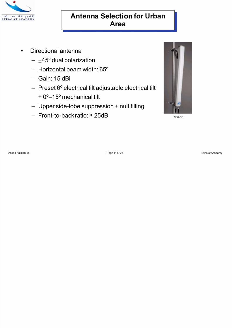
Antenna Selection for UrbanArea
• Directional antenna
– ±45º dual polarization
– Horizontal beam width: 65º
– Gain: 15 dBi – Preset 6º electrical tilt adjustable electrical tilt
+ 0º –15º mechanical tilt
– Upper side-lobe suppression + null filling
– Front-to-back ratio: ≥ 25dB

7/29/2019 chapter_6 s
http://slidepdf.com/reader/full/chapter6-s 12/36
Etisalat Academy Anand Alexander Page 12 of 25
Antenna Selection for RuralArea
• Environment characteristics inrural area
– Sparse BS location
– Low traffic
– Wide coverage required
• Directional antenna
– Vertical polarization – Horizontal beam width: 90º
– Gain: 18 dBi
– No preset tilt
• Omni-antenna
– Vertical polarization
– Gain: 11 dBi
– No preset tilt

7/29/2019 chapter_6 s
http://slidepdf.com/reader/full/chapter6-s 13/36
Etisalat Academy Anand Alexander Page 13 of 25
Antenna Selection for Suburb
• In selecting an antenna for a suburb, thesuggestions on the antenna selection for urban area or rural area can bereferenced
• An omni antenna is not recommended, in
order to facilitate smooth upgrade in thefuture
• In a suburb, if the antenna uses a tiltangle, the tilt angle should be small

7/29/2019 chapter_6 s
http://slidepdf.com/reader/full/chapter6-s 14/36
Etisalat Academy Anand Alexander Page 14 of 25
Antenna Selection for Road
• Directional antenna
– Horizontal beam width: 30º; gain: 21 dBi
– Vertical polarization; no preset tilt
• "8"-shaped antenna
– Bidirectional horizontal beam width: 70º; gain: 14 dBi
– Vertical polarization; no preset tilt
• Heart-shaped antenna
– Horizontal beam width: 210º; gain: 12 dBi
– Vertical polarization; no preset tilt

7/29/2019 chapter_6 s
http://slidepdf.com/reader/full/chapter6-s 15/36
Etisalat Academy Anand Alexander Page 15 of 25
Selection of an Indoor Antenna
• Omni-antenna
– Vertical polarization; gain: 2 dBi
– Horizontal beam width: 360º; vertical beam width: 90º
• Directional plate antenna
– Vertical polarization; gain: 7 dBi
– Horizontal beam width: 90º; vertical beam width: 60º
• Log periodic antenna (a kind of wideband antenna)
– Vertical polarization; gain: 11.5 dBi
– Horizontal beam width: 55º; vertical beam width: 50º
7/29/2019 chapter_6 s
http://slidepdf.com/reader/full/chapter6-s 16/36
Etisalat Academy Anand Alexander Page 16 of 25
Principles for Antenna HeightDesign
• For a flat urban area, the effective height of an antenna is usually
about 25m
• For a suburb or rural area, the height of the antenna can be about
40m
• A too high antenna may lower the coverage level beside the antenna
(a blind zone under the tower), which is more severe for an omni-
antenna
• A too high antenna may result in cross coverage, increase the
interference, and affect the network performance

7/29/2019 chapter_6 s
http://slidepdf.com/reader/full/chapter6-s 17/36
Etisalat Academy Anand Alexander Page 17 of 25
Principles for AntennaAzimuth Design
• The central lobe of the antenna should face the high-traffic area to improve
the signal strength and call quality
• For the urban area, the overlapping coverage ratio of the adjacent cells
should not exceed 10%
• For the suburb or rural area, the separation angle between the antenna
directions of the adjacent cells should be not lower than 90º
• For the high-density urban area, the central lobe of the antenna should not
face a straight street

7/29/2019 chapter_6 s
http://slidepdf.com/reader/full/chapter6-s 18/36
Etisalat Academy Anand Alexander Page 18 of 25
Principles for Antenna TiltDesign
• The antenna tilt technology can effectively control the coverage and
reduce the intra-system interference
• The antenna tilt angle should be determined according to the situation.
It should reduce the interference between the cells with the same
frequency and meet the coverage requirement
• In designing the antenna tilt angle, factors such as transmit power of
BS, antenna height, cell coverage, and wireless propagation
environment should be considered

7/29/2019 chapter_6 s
http://slidepdf.com/reader/full/chapter6-s 19/36
Etisalat Academy Anand Alexander Page 19 of 25
Requirement on InstallingSpace Diversity
• In case of space diversity, the distance between two receive antennas
should be 12 – 18λ, 1λ= 0.15m (2GHz)
• The effect of the vertical diversity is the same as that of the horizontal
diversity only when the vertical diversity distance is 5 –6 times the
horizontal diversity distance
7/29/2019 chapter_6 s
http://slidepdf.com/reader/full/chapter6-s 20/36
Etisalat Academy Anand Alexander Page 20 of 25
PILOT POLLUTION

7/29/2019 chapter_6 s
http://slidepdf.com/reader/full/chapter6-s 21/36
Etisalat Academy Anand Alexander Page 21 of 25
Concept of Pilot Pollution
• Concept of pilot pollution
– Pilot pollution means that there are too
many strong pilots within the coverage,
but none of the pilots is dominant
• Criteria of pilot pollution – There are more than 3 pilots with
Ec > -95 dBm
– The level difference between the
strongest pilot and the fourth strongest
pilot is < 5 dB

7/29/2019 chapter_6 s
http://slidepdf.com/reader/full/chapter6-s 22/36
Etisalat Academy Anand Alexander Page 22 of 25
Effect of Pilot Pollution
• Pilot pollution is specific to the CDMA system CDMA and greatly
affects the network performance
• Effect of pilot pollution
– High BLER
– Low system capacity – High call drop rate due to frequent handover
– Low access success rate due to no dominant cell

7/29/2019 chapter_6 s
http://slidepdf.com/reader/full/chapter6-s 23/36
Etisalat Academy Anand Alexander Page 23 of 25
Causes of Pilot Pollution
• The causes of the pilot pollution includes:
– Unreasonable cell layout
– Too high site or antenna
– Unreasonable azimuth or tilt angle of an antenna
– Effect of the back lobe of an antenna
– Effect of the ambient environment of the coverage

7/29/2019 chapter_6 s
http://slidepdf.com/reader/full/chapter6-s 24/36
Etisalat Academy Anand Alexander Page 24 of 25
Ways to Reduce PilotPollution
• An area with pilot Pollution can be predicted in the planning
simulation
– Optimize the planned scheme to avoid the pilot Pollution
• Optimal solution – excellent system design
– Proper site – Proper azimuth and tilt angle of antennas
– Proper transmit power and power ratio of sites

7/29/2019 chapter_6 s
http://slidepdf.com/reader/full/chapter6-s 25/36
Etisalat Academy Anand Alexander Page 25 of 25
2G/3G CO-SITING

7/29/2019 chapter_6 s
http://slidepdf.com/reader/full/chapter6-s 26/36
Etisalat Academy Anand Alexander Page 26 of 25
2G/3G Co-located Site

7/29/2019 chapter_6 s
http://slidepdf.com/reader/full/chapter6-s 27/36
Etisalat Academy Anand Alexander Page 27 of 25
Interference from Other System
1880~1920MHz,
2010~2025 MHz
TDD mode
TD-SCDMA
2110 ~ 2170 MHz
1920 ~ 1980 MHz
WCDMA
935 ~ 960 MHz
890 ~ 915 MHz
GSM 900
1900 MHz ~
1915 MHz
TDD mode
PDC (PHS)
1805 ~ 1880 MHzDownlink
1710 ~ 1785 MHzUplink
GSM (DCS) 1800
1880~1920MHz,
2010~2025 MHz
TDD mode
TD-SCDMA
2110 ~ 2170 MHz
1920 ~ 1980 MHz
WCDMA
935 ~ 960 MHz
890 ~ 915 MHz
GSM 900
1900 MHz ~
1915 MHz
TDD mode
PDC (PHS)
1805 ~ 1880 MHzDownlink
1710 ~ 1785 MHzUplink
GSM (DCS) 1800
GSM 900 DCS1800 Tx PDC (PHS) WCDMATD-SCDMA

7/29/2019 chapter_6 s
http://slidepdf.com/reader/full/chapter6-s 28/36
Etisalat Academy Anand Alexander Page 28 of 25
Interference from Other System
•GSM1800 BTS can
have up to – 80 dBm/
0.4 MHz spurious
emissions at the
antenna connector
•Thermal noise floor for WCDMA = -108
dBm
=> 28 dB [-108 dBm -
(-80 dBm) ] isolation
needed between
GSM1800 and
WCDMA

7/29/2019 chapter_6 s
http://slidepdf.com/reader/full/chapter6-s 29/36
Etisalat Academy Anand Alexander Page 29 of 25
Harmonic Distortion

7/29/2019 chapter_6 s
http://slidepdf.com/reader/full/chapter6-s 30/36
Etisalat Academy Anand Alexander Page 30 of 25
M Distortion from GSM1800DL to WCDMA UL

7/29/2019 chapter_6 s
http://slidepdf.com/reader/full/chapter6-s 31/36
Etisalat Academy Anand Alexander Page 31 of 25
2G/3G Isolation Methods

7/29/2019 chapter_6 s
http://slidepdf.com/reader/full/chapter6-s 32/36
Etisalat Academy Anand Alexander Page 32 of 25
Planning Rules in Co-Siting
Isolation requirement: 50 dB
GSM-WCDMA co-sitingis possible if antenna isolation requirement is
fulfilled
• By proper antenna placement
• Minimum Horizontal distance (~0.3 m)
• Minimum Vertical distance (0.25 m)
Di-or triplexeris needed in case feeder and antenna is shared between
different systemsTighter filtering is needed in Antenna line of Non-compliant GSM BTS
to avoid the TX power interference to WCDMA Rx

7/29/2019 chapter_6 s
http://slidepdf.com/reader/full/chapter6-s 33/36
Etisalat Academy Anand Alexander Page 33 of 25
Co-transmission
BTS
NodeB
E1/SDH(Abis)
Nx64kbps
BTS
NodeBE1/SDH(Iub)
E1
BTS
NodeBE1/SDH(Iub)
E1
• At the early stage of WCDMA construction, GSM provides E1/SDHtransmission resources for the WCDMA
• At the mature stage of the WCDMA, the required capacity of the
WCDMA system is high, and WCDMA can provide transmission
channels for the GSM
7/29/2019 chapter_6 s
http://slidepdf.com/reader/full/chapter6-s 34/36
Etisalat Academy Anand Alexander Page 34 of 25
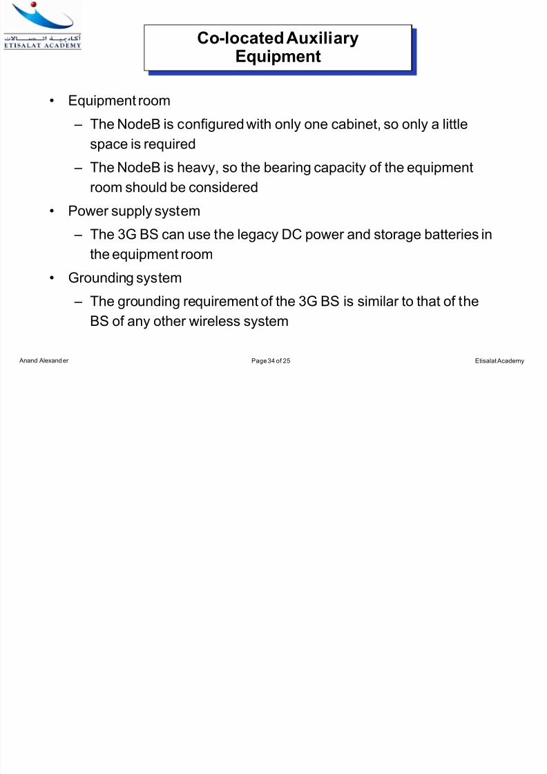
Co-located AuxiliaryEquipment
• Equipment room – The NodeB is configured with only one cabinet, so only a little
space is required
– The NodeB is heavy, so the bearing capacity of the equipment
room should be considered
• Power supply system
– The 3G BS can use the legacy DC power and storage batteries in
the equipment room
• Grounding system
– The grounding requirement of the 3G BS is similar to that of the
BS of any other wireless system

7/29/2019 chapter_6 s
http://slidepdf.com/reader/full/chapter6-s 35/36
Etisalat Academy Anand Alexander Page 35 of 25
Co-located AuxiliaryEquipment
• Cable rack
– The legacy indoor and outdoor cable racks are recommended. If
necessary, cable racks can be added
• Air conditioner
– The NodeB causes much heat, so it is necessary to reconsider the capability of the air conditioners in case of co-located
equipment room
• Co-located feeder window
– In general, there are several holes in the feeder window in the
equipment room. They can be shared by two sets of systems withgeneral capacity configuration

7/29/2019 chapter_6 s
http://slidepdf.com/reader/full/chapter6-s 36/36
Question and Answers
Discussion


![Population and Community Ecology - APES - Homerobertsenvironment.weebly.com/uploads/3/8/1/7/38176221/chapter_6.pdf · Population and Community Ecology [Notes/Highlighting] ... individuals,](https://static.fdocuments.us/doc/165x107/5b84f3757f8b9ae0498d4374/population-and-community-ecology-apes-ho-population-and-community-ecology.jpg)


