Chapter5 Serial Port Operation - Home Pages of All Faculty at KFUPM
30
By: Masud-ul-Hasan 1 Chapter 5 Serial Port Operation (I. Scott MacKenzie)
Transcript of Chapter5 Serial Port Operation - Home Pages of All Faculty at KFUPM

By: Masud-ul-Hasan1
Chapter 5Serial Port Operation
(I. Scott MacKenzie)

By: Masud-ul-Hasan2
Introduction• 8051 includes an on-chip serial port that can
operate in four modes over a wide range of frequencies.
• Essential function of serial port is to perform parallel-to-serial conversion for output data, and serial-to-parallel conversion for input data.
• Transmission bit is P3.1 on pin 11 (TXD) and reception bit is P3.0 on pin 10 (RXD).
• Features full duplex (simultaneous reception and transmission).

By: Masud-ul-Hasan3
• Two SFRs (SBUF & SCON) provide software access to serial port. – Writing to SBUF loads data to be transmitted and
reading SBUF accesses received data. – SCON is a bit addressable register containing status
bits and control bits. Control bits set the operating mode and status bits indicate the end of a character transmission or reception. The status bits are tested in software or programmed to cause an interrupt.
• Serial port frequency of operation (baud rate) can be fixed or variable. – Fixed is derived from on-chip oscillator and variable is
supplied by Timer 1 which must be programmed accordingly.
Introduction (Contd.)

By: Masud-ul-Hasan4
SCON : Serial Port CONtrol Register (098H)
SMO SM1 SM2 REN TB8 RB8 TI RI
- SM0, SM1 : Serial Port Mode bitsMode Baud Rate00 = Mode 0 : Shift register I/O Fixed (oscillator frequency/12)01 = Mode 1 : 8-bit UART Variable (set by timer)10 = Mode 2 : 9-bit UART Fixed (osc frq/32 or osc frq/64 )11 = Mode 3 : 9-bit UART Variable (set by timer)
- SM2 : Serial Port Mode bitMode 0 : Not used.Mode 1 : If SM2 = 0 : Normal Operation.
If SM2 = 1 : Ignore bytes with no stop bit.Modes 2 & 3 : If SM2 = 0 : Set RI (receive interrupt) on all bytes.
If SM2 = 1 : Set RI only on bytes where 9th bit is 1.

- REN: Receiver enable. Must be set to receive characters.- TB8: Transmit bit 8. Ninth bit transmitted (in modes 2
and 3); set/cleared by software.- RB8: Receive bit 8. Ninth bit received (in modes 2 and 3):
Mode 0 : Not used.Mode 1 : Stop bit.
Mode 2, 3 : Ninth data bit.- TI: Transmit interrupt flag. Set at end of character
transmission; cleared by software.- RI: Receive interrupt flag. Set at end of character
reception; cleared by software.
SCON (contd.)
By: Masud-ul-Hasan5

By: Masud-ul-Hasan6
Serial Interface- Full duplex UART (Universal Asynchronous Receiver
/Transmitter is a device that receives and transmits serial data with each data character preceded by a start bit “0”and followed by a stop bit “1”). Sometimes a parity bit is inserted between the last data bit and the stop bit.
- The essential operation of a UART is to perform parallel-to-serial conversion for output data, and serial-to-parallel conversion for input data.
- 10 or 11 bit frames.- Interrupt driven.- Registers:
SCON - Serial port control register.SBUF - Read received data.
- Write data to be transmitted.

By: Masud-ul-Hasan7
Serial Port Block DiagramTXD(P3.1)
RXD(P3.0)
SBUF(write only)
SBUF(read only)
Shift RegisterCLKCLK
Baud rate clock(transmit)
Baud rate clock(receive)
DQ
(LSB First) (LSB First)
8051 Internal Bus

By: Masud-ul-Hasan8
Mode 0: 8-Bit Shift Register Mode. Terms RXD & TXD are misleading in this mode. RXD line is used for both input and output. TXD line serves as the clock.
• Eight bits are transmitted and received with the LSB first. Baud Rate is fixed at 1/12 of on-chip oscillator frequency.
• Transmission is initiated by any instruction that writes data to SBUF. Data are shifted out on RXD line with clock pulses sent out by the TXD line. Each transmitted bit is valid on the RXD pin for one machine cycle. E.g., MOV SBUF, A
• Reception is initiated when the REN is 1 and the RI is 0. REN is set at the beginning of the program, and then clear RI to begin a data input operation. The clocking of data into serial port occurs on the positive edge of TXD.
Serial Interface Modes of Operation (Mode 0)

By: Masud-ul-Hasan9
Serial Interface Modes of Operation (Mode 1)
Mode 1: Serial port operates as an 8-bit UART with a variable baud rate.10-bits are transmitted on TXD or received on RXD. Start bit (always 0), 8 data bits (LSB first), and a stop bit (always 1). For a receive operation, the stop bit goes into RB8 in SCON. Baud Rate Clock is variable using Timer 1 overflow or external count input.
• Transmission is initiated by writing data to SBUF. Shifted data are outputted on the TXD line beginning with the start bit. The transmit interrupt flag (TI) is set as soon as the stop bit appears on TXD.
• Reception is initiated by a 1-to-0 transition on RXD.
By: Masud-ul-Hasan10
Serial Interface Modes of Operation (Mode 2)
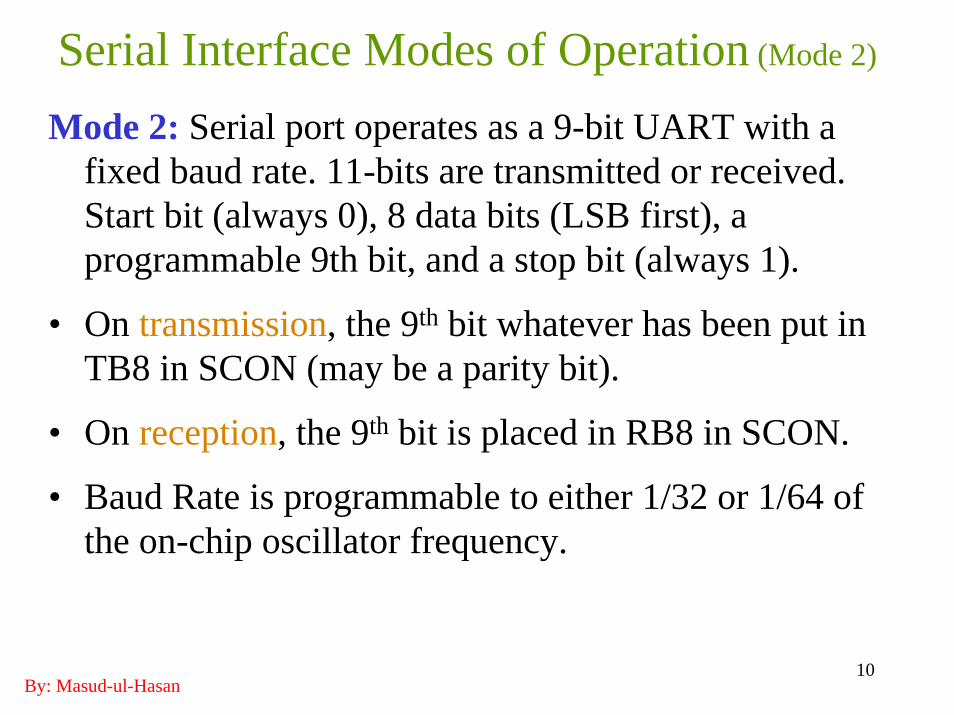
Mode 2: Serial port operates as a 9-bit UART with a fixed baud rate. 11-bits are transmitted or received. Start bit (always 0), 8 data bits (LSB first), a programmable 9th bit, and a stop bit (always 1).
• On transmission, the 9th bit whatever has been put in TB8 in SCON (may be a parity bit).
• On reception, the 9th bit is placed in RB8 in SCON.
• Baud Rate is programmable to either 1/32 or 1/64 of the on-chip oscillator frequency.

By: Masud-ul-Hasan11
Serial Interface Modes of Operation (Mode 3)
Mode 3: Serial port operates as a 9-bit UART with a variable baud rate. 11-bits are transmitted or received. Baud Rate is programmable and provided by the Timer 1 overflow or external input.
Summary:Baud rate: Fixed in modes 0 & 2, variable in modes 1 & 3Data Bits: Eight in mode 1, nine in modes 2 & 3

By: Masud-ul-Hasan12
Initialization• Receiver Enable Bit (REN): must be set by software to
enable the reception of characters at the beginning of a program when the serial port, timers, etc. are initialized. The instructions are
SETB REN or MOV SCON, #xxx1xxxxB• The 9th Bit: transmitted must be loaded into TB8 by
software and received is placed in RB8.• Adding a Parity Bit: is a common use of 9th bit. E.g., if
communication requires 8 data bits plus even parityMOV C, P ; Put even parity bit in C flagMOV TB8, C ; This becomes the 9th data bit in TB8MOV SBUF, A ; Move 8 bits from ACC to SBUF

By: Masud-ul-Hasan13
• E.g., if communication requires 8 data bits plus odd parityMOV C, P ; Put even parity bit in C flagCPL C ; Convert to odd parityMOV TB8, C ; This becomes the 9th data bit in TB8 MOV SBUF, A ; Move 8 bits from ACC to SBUF
• Parity can be used in mode 1 also if the 7 data bits are used. E.g., 7-bit ASCII code with even parity can be transmitted as follows:
CLR ACC.7 ; Ensure MSB is clear to get correct ParityMOV C, P ; Put even parity bit in C flagMOV ACC.7, C ; Copy even parity bit into MSBMOV SBUF, A ; Send character
Initialization (Contd.)

By: Masud-ul-Hasan14
Interrupt Flags (RI &TI)• RI & TI in SCON play an important role in serial
communications. Both bits are set by hardware but must be cleared by software.– RI is set at the end of character reception and indicates
“receive buffer full”.– This condition is tested in software or programmed to
cause an interrupt.– If software wishes to input a character from the device
connected to the serial port, it must wait until RI is set, then clear RI and read the character from SBUF.WAIT: JNB RI, WAIT ; Check RI until set
CLR RI ; Clear the flagMOV A, SBUF ; Read character
By: Masud-ul-Hasan15
Interrupt Flags (RI &TI) contd.
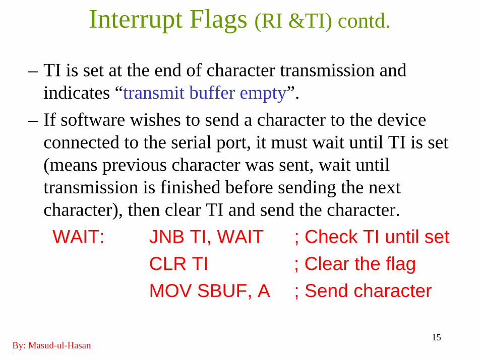
– TI is set at the end of character transmission and indicates “transmit buffer empty”.
– If software wishes to send a character to the device connected to the serial port, it must wait until TI is set (means previous character was sent, wait until transmission is finished before sending the next character), then clear TI and send the character.WAIT: JNB TI, WAIT ; Check TI until set
CLR TI ; Clear the flagMOV SBUF, A ; Send character

By: Masud-ul-Hasan16
Multiprocessor Communication• Serial Communication Modes 2 and 3 allow one
"Master" 8051 to control several “Slaves” 8051.
• The serial port can be programmed to generate an interrupt (RI) if the 9th data bit = 1 by setting the SM2bit in SCON.
• The TXD outputs of the slaves are tied together and to the RXD input of the master. The RXD inputs of the slaves are tied together and to the TXD output of the master.
• Each slave is assigned an address. Address bytes transmitted by the master have the 9th bit = 1 & data bytes have it = 0.
By: Masud-ul-Hasan17
Multiprocessor Communication (Contd.)• When the master transmits an address byte, all the
slaves are interrupted. The slaves then check to see if they are being addressed or not.
• The addressed slave will clear its SM2 bit and prepare to receive the data bytes that follows and the slaves that weren’t addressed leave their SM2 bits set and go about their business, ignoring the incoming data bytes. They will be interrupted again when the next address byte is transmitted by the master processor.

By: Masud-ul-Hasan18
Baud Rates• Baud rate is also affected by a bit in the PCON register.
PCON.7 is SMOD bit. If SMOD = 1, baud rate will be doubled in modes 1, 2 and 3.
• Mode 2 baud rate is the 1/64th the oscillator frequency (SMOD = 0) and can be doubled to 1/32nd the oscillator frequency (SMOD = 1).
• PCON is not bit-addressable, setting SMOD without altering the other bits requires a “read-modify-write”operation as follows:
MOV A, PCON ; Get current value of PCONSETB ACC.7 ; Set SMODMOV PCON, A ; Write value back to PCON

By: Masud-ul-Hasan19
Using Timer 1 as Baud Rate Clock• Usually the timer is used in auto-reload mode and TH1 is loaded
with a proper reload value.• Formula for the baud rate in modes 1 and 3 is
Baud Rate = Timer 1 Overflow Rate / 32e.g., For 1200 baud
1200 = Timer 1 Overflow Rate / 32Timer 1 Overflow Rate = 1200 * 32 = 38400 Hz
• Timer must overflow at a rate of 38.4 kHz and the timer is clocked at a rate of 1 MHz (1000 kHz), overflow required every 1000/38.4= 26.04 clocks, so
MOV TH1, # -26• Due to rounding, there is a slight error in the resulting baud rate.
Up to 5% is tolerable using asynchronous communications. Exact baud rates are possible using an 11.059 MHz crystal (Table 5-3).

By: Masud-ul-Hasan20
Baud Rate SummaryBaud Rate
Crystal Frequency
SMOD TH1 Reload Value
Actual Baud Rate
Error
1200 12.000MHz 0 -26(E6H) 1202 0.16%2400 12.000MHz 0 -13(F3H) 2404 0.16%9600 12.000MHz 1 -7(F9H) 8923 7%1200 11.059MHz 0 -24(E8H) 1200 0%2400 11.059MHz 0 -12(F4H) 2400 0%9600 11.059MHz 0 -3(FDH) 9600 0%19200 11.059MHz 1 -3(FDH) 19200 0%

By: Masud-ul-Hasan21
Initializing the Serial PortTo initialize the serial port to operate as an 8-bit UART at 2400 baud.
ORG 0000HMOV SCON,#52H ;serial port mode 1MOV TMOD,#20H ;timer 1, mode 2MOV TH1, # -13 ;reload count for 2400 baudSETB TR1 ;start timer 1END

By: Masud-ul-Hasan22
Initializing the Serial PortSMO SM1 SM2 REN TB8 RB8 TI RISCON:
0 1 0 1 0 0 1 0 (52H)• (SM0/SM1=0/1) sets serial port into 8-bit UART, (REN=1) enables the serial port to receive characters, (TI=1) allows transmission of the first character by indicating that the transmit buffer is empty.
GATE C/T M1 M0 GATE C/T M1 M0TMOD:0 0 1 0 0 0 0 0 (20H)
• (M1 M0=1 0) puts Timer 1 into auto-reload mode. TF1 TR1 TF0 TR0 IE1 IT1 IE0 IT0TCON:
0 1 0 0 0 0 0 0 (40H)• (TR1=1) turns ON Timer 1.
Tb7 b6 b5 b4 b3 b2 b1 b01 1 1 1 0 0 1 1 (F3H)
TH1:
• Loads the re-load value –13 or F3H in the TH1 register.

By: Masud-ul-Hasan23
RS232• PC: COM1, COM2 (MODEM & RS232)• RS232 is set by Electronics Industries Association
(EIA) in 1960.• 1963: RS232A• 1965: RS232B• 1969: RS232C• RS232 is a serial I/O interfacing standard; however,
since the standard was set long before the advent of the TTL logic family, its input and output voltage levels are not TTL compatible.
• TTL is Transistor-Transistor Logic family (Bipolar transistor) in 1968.

By: Masud-ul-Hasan24
Line Driver: MAX232/233• TTL: +5V => Logic 1, 0V => Logic 0• RS232: -3V => Logic 1, +3V => Logic 0 • So RS232 is not compatible to TTL. For this
reason, to connect any RS232 to a microcontroller system, we must use “Voltage Converters” such as MAX232 or MAX233 to convert the TTL logic levels to the RS232 voltage levels, and viceversa.
• MAX232/233 IC chips is referred to as “Line Driver”.

By: Masud-ul-Hasan25
RS232 Connector: DB-25 & DB-9DB: Data Bus ConnectorPins: RxD, TxD, GND will be connected only.RS232: Pin2 RxD, Pin3 TxD, Pin5 GND
Female MaleDB-25
15
69
DB-9

By: Masud-ul-Hasan26

By: Masud-ul-Hasan27
By: Masud-ul-Hasan28
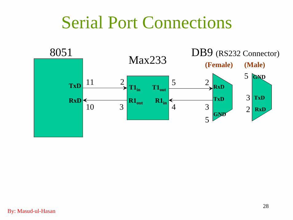
Serial Port Connections8051 DB9 (RS232 Connector)
2
35
TxD
RxD TxD
RxD
GND
T1in
R1in
T1out
R1out
(Female)Max233 (Male)5
32
TxD
RxD
GND211 5
10 3 4

By: Masud-ul-Hasan29
Output ACSII Code Set Using Interrupt;Ex 6-3 dump ASCII codes to serial port
ORG 0000HLJMP MainORG 0023H ;serial port vectorLJMP SPISRORG 0030H ;main entry point
Main: MOV TMOD,#20H ;Timer 1 mode 2MOV TH1,#-26 ;use 1200 baudSETB TR1 ;start T1MOV SCON,#42H ;mode1, set TI to force first
;interrupt; send 1st char.MOV A,#20H ;send ASCII space firstMOV IE,#90H ;enable SP interruptSJMP $ ;do nothing

By: Masud-ul-Hasan30
Output ACSII Code Set Using InterruptSPISR: CJNE A,#7FH,Skip ;if ASCII code = 7FH
MOV A,#20H ;wrap back to 20HSkip: MOV SBUF,A ;start transmission
INC ACLR TI ;clear TI flagRETI
The CPU speed is much higher than 1200 baud serial transmission.Therefore, SJMP executes a very large percentage of the time.Time for one char = (1/1200 baud)(8+1+1) = 8333.3 µs compared to 1 µs machine cycle!We could replace SJMP instruction with other useful instructions doing other things.