Chapter4 Experiment2:...
9
Chapter 4 Experiment 2: Snell’s Law of Refraction 4.1 Introduction In this and the following lab the light is viewed as a ray. A ray is a line that has an origin but does not have an end. Light is an electromagnetic disturbance and, as such, is described using Maxwell’s equations, which expresses the relationship between the electric and magnetic fields in an oscillating wave. Light propagates as a wave; yet, many optical phenomena can be explained by describing light in terms of rays. In the model for light, rays in a homogeneous medium travel in straight lines. This model is referred to as Geometric Optics and is a very elementary theory. In this theory light travels from its origin at a source in a straight line, unless it encounters a boundary to the medium. Beyond this boundary may be another medium which is distinguished by having a speed of light different from the original medium. In addition, light may be reflected at the boundary back into the original medium. A light ray that returns to the original medium is said to be “reflected”. A ray that passes into the other medium is said to be “refracted”. In most interactions between light and a boundary, both reflection and refraction occur. In order to frame laws that govern these phenomena we must define some terms. The boundary between two media is defined as a surface. The orientation of a surface at any specific point is characterized by a line perpendicular to the surface that we call the normal. A ray may encounter a boundary at any arbitrary incidence angle. The angle of incidence is measured with respect to the normal line. A reflected ray will have an angle of reflection that is also measured with respect to the normal. The refracted ray will be oriented by the angle of refraction measured between the ray and the normal to the surface. Checkpoint For geometric Optics what assumption is made about the nature of light? 43
Transcript of Chapter4 Experiment2:...
Chapter 4
Experiment 2:Snell’s Law of Refraction
4.1 Introduction
In this and the following lab the light is viewed as a ray. A ray is a line that has anorigin but does not have an end. Light is an electromagnetic disturbance and, as such, isdescribed using Maxwell’s equations, which expresses the relationship between the electricand magnetic fields in an oscillating wave.
Light propagates as a wave; yet, many optical phenomena can be explained by describinglight in terms of rays. In the model for light, rays in a homogeneous medium travel instraight lines. This model is referred to as Geometric Optics and is a very elementarytheory. In this theory light travels from its origin at a source in a straight line, unless itencounters a boundary to the medium. Beyond this boundary may be another mediumwhich is distinguished by having a speed of light different from the original medium. Inaddition, light may be reflected at the boundary back into the original medium. A light raythat returns to the original medium is said to be “reflected”. A ray that passes into the othermedium is said to be “refracted”. In most interactions between light and a boundary, bothreflection and refraction occur.
In order to frame laws that govern these phenomena we must define some terms. Theboundary between two media is defined as a surface. The orientation of a surface at anyspecific point is characterized by a line perpendicular to the surface that we call the normal.A ray may encounter a boundary at any arbitrary incidence angle. The angle of incidenceis measured with respect to the normal line. A reflected ray will have an angle of reflectionthat is also measured with respect to the normal. The refracted ray will be oriented by theangle of refraction measured between the ray and the normal to the surface.
CheckpointFor geometric Optics what assumption is made about the nature of light?
43
CHAPTER 4: EXPERIMENT 2
What distinguishes the two media is that the speed of light is different from one mediumto the other. We define the index of refraction n to be the measure of how much differentthe speed of light is in a certain medium from that of light through a vacuum. Light travelsthrough a vacuum at 299,792,458m/s. This speed is thought to be a universal constant andthe highest speed allowed in nature as postulated in Einstein’s theory of Special Relativity.We use the symbol c to represent this speed.
The index of refraction is a characteristic of the medium. It is the only thing thatdistinguishes one medium from another in geometric optics. It is defined as the ratio of thespeed of light in a vacuum to the speed in a particular medium of interest,
n = c
vor v = c
n. (4.1)
Therefore, the value of the index of refraction is always greater than unity. Gasses have anindex of refraction close to 1 (nair = 1.00028), while for water the index is about 1.33 andfor plastic it is approximately 1.4. Depending on the type of glass the index of refraction ofglass can vary from 1.5 to 1.7.
Normally we might think that the index of refraction is a constant that is the same forall light. The index of refraction actually depends on the frequency (color) of the light waveto a small degree across the visible part of the spectrum and as such is different for differentcolors of light. The rules for reflection of light are:
1) The angle of incidence is equal to the angle of reflection,
θ1 = θ′1 (4.2)
where θ1 is the angle of incidence and θ′1 is the angle of the reflected ray thatpropagates in the same medium. (This is the commonly known rule, but this nextrule is rarely stated though equally important)
2) The incident ray, the reflected ray, and the normal to the surface, all lie in thesame plane.
CheckpointWhat is the law of reflection?
We will not formally investigate these rules in this lab although you will be able to observethe phenomena of reflection as a side issue while performing this lab experiment. The rulesfor refraction are not so obvious although they where well known to the ancients.
1) The first rule is often cited as Snell’s Law; it is:
sin θ1
sin θ2= n2
n1or n1 sin θ1 = n2 sin θ2. (4.3)
44
CHAPTER 4: EXPERIMENT 2
where θ2 is the angle of refraction of the ray that is transmitted into the secondmedium.
2) The incident ray, the refracted ray and the normal to the surface, all lie in thesame plane.
CheckpointWhat is Snell’s Law? What phenomenon does Snell’s Law describe?
In general the path of a light ray is reversible in that if a light ray were to be reversed itwould follow the same path. A ray traveling from a low index of refraction to a high index ofrefraction will experience a bending toward the normal. However a ray passing from a highindex of refraction to a lower index will experience a bending away from the normal. Theangle of refraction will be larger than the angle of incidence. So, what happens when theangle of refraction is greater than 90◦ for a given incidence angle. In this case light cannotbe transmitted through the interface and as such it is reflected totally. The efficiency for thisreflection is 99.99% (as compared to 95% for a typical silvered surface mirror). The largestangle for which a ray will be transmitted is the critical angle. One can show that the sineof this angle is the inverse of the ratio of the index of refraction of the first medium to theindex of the second medium. If the second medium is air (n = 1.00028), the sine of the angleis effectively the reciprocal of the index of refraction of the first material.
CheckpointIn optics angles are always measured with respect to what?
4.2 The Experiment
The experiment consists of a single thin bundle of light rays exiting a light box. This raywill be incident upon a ‘D’ shaped dielectric so that we may deduce whether the laws ofreflection and of refraction are obeyed by the interaction between the light and the object.A picture of the experiment is shown in Figure 4.1. We should recall that ‘dielectrics’ wereplaced between capacitor plates to increase capacitance and to insulate between the plates.Our refracting medium is a transparent dielectric.
4.2.1 Reflections and Refraction
In this experiment you will use the Light Ray Box shown on the right side of Figure 4.1. Itconsists of a light source and a Multi-slit Slide Set. The light source housing is mounted on
45
CHAPTER 4: EXPERIMENT 2
a colored plastic base in which it can slide back and forth. The utility of this feature willbe explained in a future experiment. The Multi-slit Slide is a flat square piece of plastic oraluminum with notches cut into each of the four edges. The Multi-slit Slide slips into a sloton the end of the ray box to create rays of light. Choose the side with just one narrow notchand place that side down as you slip the a Multi-slit Slide into place. A single narrow beamshould be observed emerging from the ray box.
Also in this experiment you will use a turntable (goniometer) to orient the dielectricsurface. The turntable has some friction with its stationary stand, so it is suggested that youspend several minutes practicing the act of changing angles before aligning the experiment totake your data. With some care you should be able to rotate the turntable and dielectric onits stand without sliding the stand on the tabletop. Once you can do this reliably, carefullyplace the dielectric ‘D’ on the turntable as the turntable markings indicate. As long as youdo not suddenly move the turntable, friction will keep the dielectric on the turntable atthis location and will allow you to rotate the dielectric while reading the angles from theturntable’s periphery.
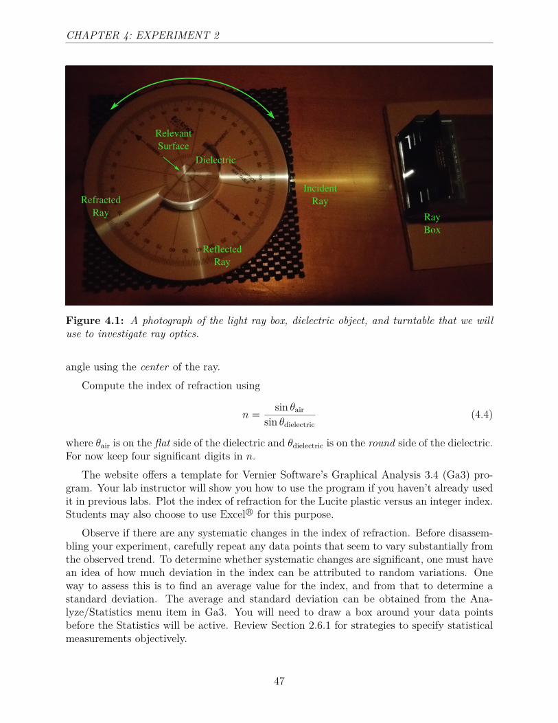
Figure 4.1 shows the experiment in progress. In the figure the light passes through thedielectric before striking the planar surface (the ‘relevant surface’ in the figure). Note thatthe ray strikes the planar surface precisely at the center of the turntable; this is also thepivot point for the turntable. As long as neither the ray box nor the turntable slides on thetabletop, this ray will always strike the relevant surface at the pivot point. In the figure itis easy to see that the incident ray is 40◦ from one side of the normal and the reflected rayis 40◦ from the opposite side of the same normal. The refracted ray has spread considerably(can you guess why?), but its refraction angle is about 73◦ (what is its uncertainty?). Isthere any trend that you note regarding these refracted rays and how they spread?
4.2.2 Index of Refraction and the Law of Reflection
Now we need to align the ray from the ray box carefully before we begin taking data.Carefully rotate the turntable so that the flat side of the dielectric faces the ray box. Carefullyslide and tilt the ray box so that the light strikes the dielectric precisely at the turntablepivot and such that both the incident light and the refracted light illuminates the protractorscale around the turntable’s periphery. Carefully rotate the turntable until the incident rayis at 0◦. At this angle only, the refracted ray should also illuminate the opposite side of theturntable at 0◦. Keeping the incident ray at 0◦, carefully adjust the ray box position to pointthe ray at the pivot point and/or carefully adjust the dielectric’s position on the turntableuntil the light ray passes straight across the turntable through the pivot point. This makesyour apparatus ready to start taking data.
Draw a nice table in your notebook (or execute Ga3 and prepare the columns and headers)to record the incident angle, the angle of reflection, the angle of refraction, and a calculatedindex of refraction. You will need 25-30 rows. Since neither 0◦ nor 90◦ will provide usefuldata, it is recommended that you begin with an incidence angle of 5◦ and that you incrementby 10◦ between measurements. Carefully record the incident angle, the angle of reflection,and the angle of refraction. (How accurately can you measure these?) Always estimate the
46
CHAPTER 4: EXPERIMENT 2
Incident
Ray
Reflected
Ray
Refracted
Ray
Relevant
Surface
Ray
Box
Dielectric
Figure 4.1: A photograph of the light ray box, dielectric object, and turntable that we willuse to investigate ray optics.
angle using the center of the ray.Compute the index of refraction using
n = sin θair
sin θdielectric(4.4)
where θair is on the flat side of the dielectric and θdielectric is on the round side of the dielectric.For now keep four significant digits in n.
The website offers a template for Vernier Software’s Graphical Analysis 3.4 (Ga3) pro-gram. Your lab instructor will show you how to use the program if you haven’t already usedit in previous labs. Plot the index of refraction for the Lucite plastic versus an integer index.Students may also choose to use Excel R© for this purpose.
Observe if there are any systematic changes in the index of refraction. Before disassem-bling your experiment, carefully repeat any data points that seem to vary substantially fromthe observed trend. To determine whether systematic changes are significant, one must havean idea of how much deviation in the index can be attributed to random variations. Oneway to assess this is to find an average value for the index, and from that to determine astandard deviation. The average and standard deviation can be obtained from the Ana-lyze/Statistics menu item in Ga3. You will need to draw a box around your data pointsbefore the Statistics will be active. Review Section 2.6.1 for strategies to specify statisticalmeasurements objectively.
47
CHAPTER 4: EXPERIMENT 2
CheckpointDo all of your reflected rays obey the Law of Reflection?
4.2.3 Total Internal Reflection
Do you have any incident rays that do not have refracted rays? Is this consistent with Snell’slaw? We would like to observe this “total internal reflection” in more detail. First, where doesthe energy in the incident light ray go if it is not transmitted through the surface? Do youobserve anything that supports your hypothesis? Second, we want to measure this “criticalangle” of incidence where the slightest rotation results in refracted light. The symmetryof the planar surface indicates that there should be two critical angles in 360◦ of rotation.Measure both of them and verify that they are the same but on opposite sides of the normal.Also observe the angles of the reflected rays; does the Law of Refection suggest a way touse these reflections to improve your critical angle measurements? If you were diving andlooking up, this would be the opening angle of a “critical cone” outside of which you couldnot see through the surface.
Use these critical angle measurements to calculate the index of refraction,
n = nair
sin θc≈ 1
sin θc,
and specify the mean and standard error (see Section 2.6.1). Compare with the value you gotin Section 4.2.2. Does it agree within the uncertainty of the first measurement as determinedfrom the standard error? Might the error in your measurement of critical angle be largeenough to explain any disagreement? Comment on this in your Analysis.
CheckpointIf two adjacent media have the same index of refraction, n, can you observe thephenomena of reflection or refraction?
CheckpointWhat is a critical angle? What are the two conditions that allow total internalreflection to take place?
48
CHAPTER 4: EXPERIMENT 2
4.2.4 Optical Fiber
One of the more recent and ubiquitous applications of total internal reflection is the opticalfiber. Fiber optics has revolutionized the communications industry. A fiber consists of along thin thread of glass called the core surrounded by an outer shell of a material with alower index of refraction called the cladding. Light entering the end of the core of an opticalfiber is transmitted or piped to the other end with very little loss in intensity even thoughthe fiber may be bent in a circular shape. The thinness of the fiber and the lower indexof refraction in the cladding ensures that light will always strike the fiber side at an anglegreater than the critical angle for total internal reflection and be totally reflected back intothe fiber. Thus the light bounces off the inside as it caroms down the length of the fiberfollowing every bend or twist.
Light is composed of thousands of discernible wavelengths (colors) and each color canbe modulated to communicate many billions of bits of information per second. Intelligiblevoice in one telephone call requires only 50,000 bits per second. One fiber can communicatehundreds of thousands of phone calls. More complex information requires more bandwidthand thus fewer channels can be communicated on a fiber.
Find the optical fiber among the items on your lab table. Be careful in handling thefiber. It is, after all, a piece of glass and will break if bent too sharply. Align one end of thefiber with the ray emerging from the ray box. Observe the light emerging from the other endof the fiber. It will look like a bright pinpoint of light. Point this end of the fiber verticallydown onto a sheet of paper on the table with the end of the fiber held about five millimetersabove the table. You should see a bright spot on the paper where the light rays coming fromthe fiber hit the paper. The light has been channeled through the fiber even around thebends as the ray bounces off the inside surface of the fiber, possibly many times. The lightpersists with little loss of intensity because of the great efficiency of these reflections that areat such steep angles to the surface normal as always to be in the regime of total reflection.
Now, carefully rotate the incident end of the fiber to introduce an angle between theincident ray and the fiber end’s normal. Observe that the spot on the paper has expandedto form a ring of light. Note these observations and try to explain them in your Data.
CheckpointIn the case of fiber optics do you expect the core or the cladding to have a greatervalue for the index of refraction? Why are optical fibers immune to electrical noise?
4.2.5 Lenticular Lenses
Most of us have walked past displays at the movie theater or the video store and noticedthat the image suddenly changed as we walked past. Some of us were very curious how thismagic happened. Before we leave today we would like to dispel some of the mystery behind
49
CHAPTER 4: EXPERIMENT 2
this marvelous invention.
redis
seen
purpleis
seenblue
isseen
red
blu
elenticular print
lenticular lens
(a) (b)
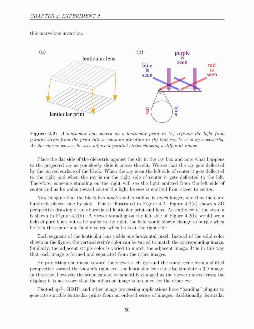
Figure 4.2: A lenticular lens placed on a lenticular print in (a) refracts the light fromparallel strips from the print into a common direction in (b) that can be seen by a passerby.As the viewer passes, he sees adjacent parallel strips showing a different image.
Place the flat side of the dielectric against the slit in the ray box and note what happensto the projected ray as you slowly slide it across the slit. We see that the ray gets deflectedby the curved surface of the block. When the ray is on the left side of center it gets deflectedto the right and when the ray is on the right side of center it gets deflected to the left.Therefore, someone standing on the right will see the light emitted from the left side ofcenter and as he walks toward center the light he sees is emitted from closer to center.
Now imagine that the block has much smaller radius, is much longer, and that there arehundreds placed side by side. This is illustrated in Figure 4.2. Figure 4.2(a) shows a 3Dperspective drawing of an abbreviated lenticular print and lens. An end view of the systemis shown in Figure 4.2(b). A viewer standing on the left side of Figure 4.2(b) would see afield of pure blue; but as he walks to the right, the field would slowly change to purple whenhe is in the center and finally to red when he is at the right side.
Each segment of the lenticular lens yields one horizontal pixel. Instead of the solid colorshown in the figure, the vertical strip’s color can be varied to match the corresponding image.Similarly, the adjacent strip’s color is varied to match the adjacent image. It is in this waythat each image is formed and separated from the other images.
By projecting one image toward the viewer’s left eye and the same scene from a shiftedperspective toward the viewer’s right eye, the lenticular lens can also simulate a 3D image.In this case, however, the scene cannot be smoothly changed as the viewer moves across thedisplay; it is necessary that the adjacent image is intended for the other eye.
Photoshop R©, GIMP, and other image processing applications have “banding” plugins togenerate suitable lenticular prints from an ordered series of images. Additionally, lenticular
50
CHAPTER 4: EXPERIMENT 2
lenses may be purchased from Amazon.com and ebay. It would be wise to consider the de-sired product (http://www.microlens.com/pages/choosing_right_lens.htm) before wastingtoo much time figuring this out for yourself.
4.3 Analysis
Verify the self-consistency of Snell’s law by comparing the two indices of refraction measuredin Section 4.2.2 and Section 4.2.3. Use the strategy in Section 2.9. What have you noticedwhile performing the experiment that might (probably does?) contribute to the differencebetween these measurements? Might these other sources of errors be large enough to explainyour differences?
4.4 Conclusions
What have you measured that you and/or your science peers might need to use in the future?What physical relations do your data support? Contradict? Which are not satisfactorily
tested? Communicate with complete sentences and define all symbols. (Or better yet, labelyour equations above and simply name them here in your Conclusions.)
How might this experiment be improved? If you were to repeat the experiment, whatwould you try to do differently and why? What applications might benefit from yourobservations?
51