ISO 128-20 Technical Drawings General Principles of Presentation
Upload
felicity-conleyCategory
view
217download
0
Chapter39
Presentation Drawings

2
Links for Chapter 39
Types of Drawings
Methods of Presentation
Rendering Procedures

3
Types of Presentation Drawings
• Presentation drawings are used to convey basic design concepts to a client
• Drawings are done with a combination of artistic and drafting skills
• Some firms hire professional architectural illustrators for complex presentation drawings

4
Types of Presentation Drawings
• Renderings– Shows shape and style of a structure– Used to describe an artistic process applied to
a drawing– Exterior drawings typically done as two-point
perspectives– Interior drawings done as a one-point
perspective

5
Rendering

6
Types of Presentation Drawings
• Elevations– Rendering that shows the shape of the
structure– Shows changes in surface
• Floor Plans– Conveys layout of interior space
– Shows room relationships and basic sizes

7
Floor Plan
DO

8
Types of Presentation Drawings
• Site Plans– Shows how the structure relates to the job site
and surrounding area– More artistic than a typical site plan
• Sections– Shows vertical relationship within a structure– Emphasis is placed on spatial relationships

9
Methods of Presentation
• Common Media– Includes sketch paper, Mylar, vellum,
illustration board, and CADD
– A pleasing effect is achieved by combining media
10
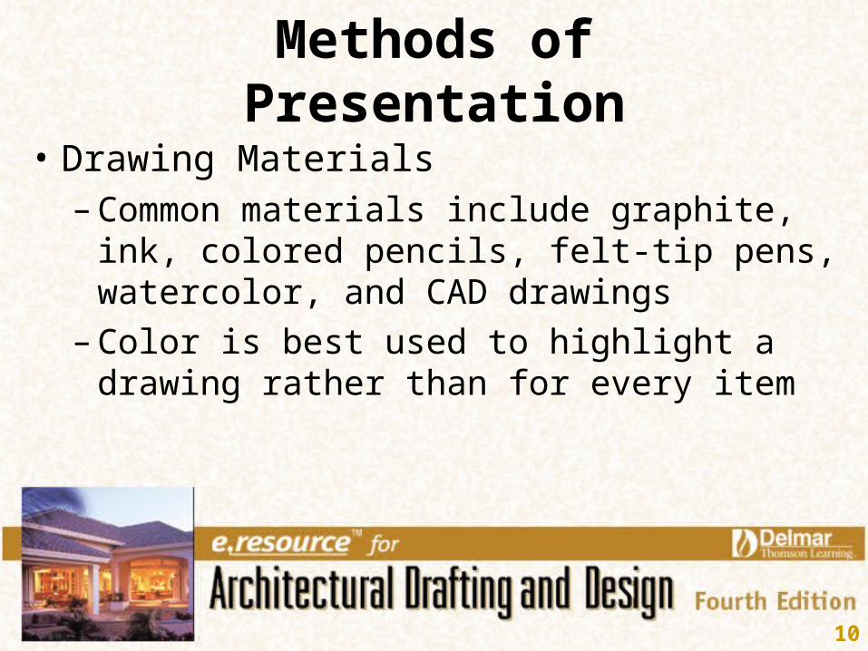
Methods of Presentation
• Drawing Materials– Common materials include graphite, ink,
colored pencils, felt-tip pens, watercolor, and CAD drawings
– Color is best used to highlight a drawing rather than for every item

11
Methods of Presentation
• Line Techniques– Mechanical lines use a straightedge
– Freehand lines are traced or created freehand
– Lettering may be placed with a lettering guide, rub-ons, or freehand

12
Line Technique

13
Rendering Procedures
• Elevations– Plants are added easily with rub-ons
– Be sure the plants are appropriate for the area of the country the structure will be in
– Draw the outlines first then fill in foilage

14
Elevations

15
Elevations

16
Rendering Procedures

17
Elevations
WINDOW FRAMECASTS SHADOWONTO GLASS
RECESSED PANELSARE SHADED BYDOOR SURFACE
TRIM CASTSSHADOWONTO SIDING
ROOFING CASTSSHADOW ONTOFASCIA
ONTO SIDING
FASCIA CASTSSHADOW
POCHE ADDEDTO GLASS AREAS

18
Rendering Procedures
• Shading– Shadows show surface changes and add a
sense of realism
– Position the light source so the best detail is seen
– Use graphite or ink for shading and a hatch pattern if CADD is being used

19
Shading
LIGHTSOURCE
SOURCELIGHT
SHADESHADE
SOURCELIGHT LIGHT
SOURCELIGHT SOURCE
OVERHANG
LOWER FLOORUPPER FLOOR
X'
X'
3X
2'-0"
2'-0"
2'-0"
SHADOW CAST BY 2'-0" OVER- HANG
SHADOW CAST BY 6'-0" OVER- HANG

20
Rendering Procedures
• Floor Plan– Use of the presentation floor plan determines
the scale
– Templates can be used for easy drawing
– Add symbols for flooring and landmarks
– Limit written specifications, except for rooms, appliances, and general titles

21
Floor Plan

22
Floor Plan
MAIN FLOOR PLANSCALE : 1/4" = 1'-0"
FAMILY
LIVING
DINING
KIT.
SHOP

23
Rendering Procedures
• Site Plan– Add driveways, decks, pools, and walks
– Only specify basic sizes on the site plan
• Sections– Draw at same scale as the floor plan
– Specify room names and ceiling heights

24
Site Plan
C
66.90'
134.92'
N88 06' 14" W
PROPOSED 2 STORY S.F.R.F. F. ELEV 101.50'
5'-0"
61'-0"
SITE PLAN1/8" 1'-0"
MIBRADA LOOP

25
Sections
LIVING FAMILY
BED. 1BATH
SECTION