Chapter2 Geometrical Optics 1 2
89
Geometrical optics (ray optics) is the simplest version of optics. Ray optics
-
Upload
maeya-pratama -
Category
Documents
-
view
21 -
download
0
description
optik
Transcript of Chapter2 Geometrical Optics 1 2
Geometrical optics (ray optics) is the simplest version of optics.
Rayoptics
GEOMETRICAL OPTICS
IMAGE FORMATION WITH LENSES

If the objects encountered by light are large compared to wavelength, the equations of propagation can be greatly simplified
i.e. the wave‐phenomena (scattering, interference, etc) are neglected
In homogeneous media, light travels in straight lines = rays
Assumption
Isotropic: same optical properties across the media means constant index of refraction.
Principle of reversibility: if object and image points switch places light rays will go through the same path only in opposite direction.
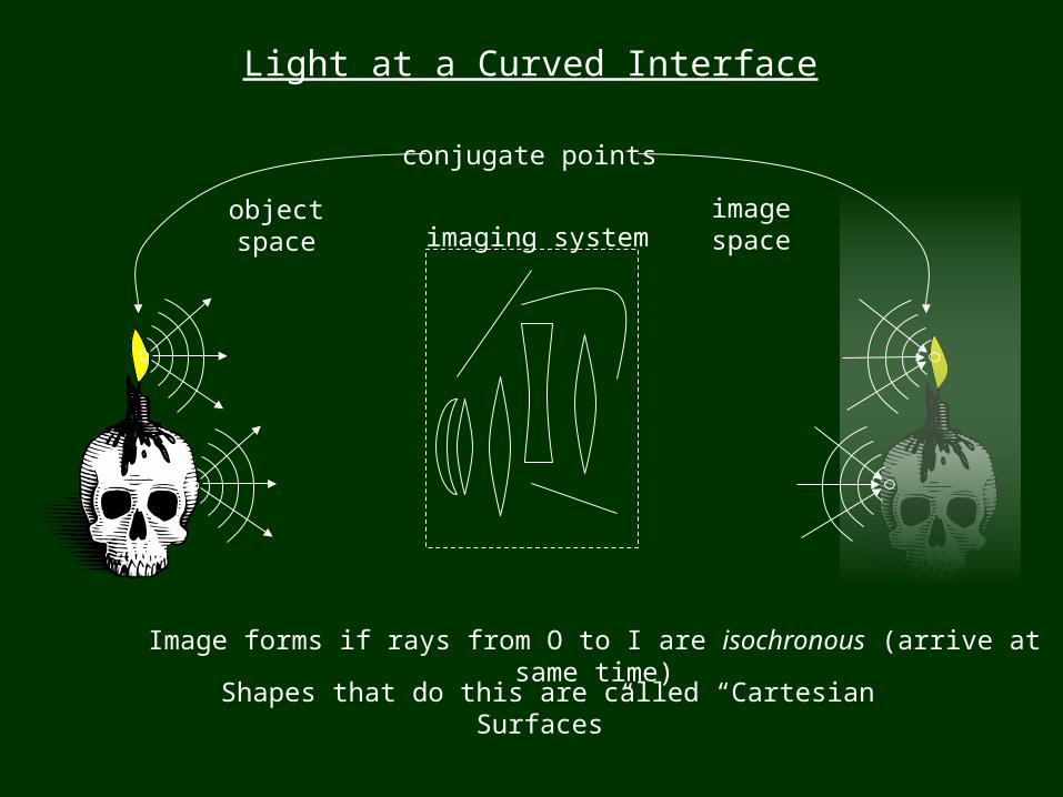
object space
image space
conjugate points
Shapes that do this are called “Cartesian Surfaces”
Light at a Curved Interface
imaging system
Image forms if rays from O to I are isochronous (arrive at same time)
I
S
P(x,y)
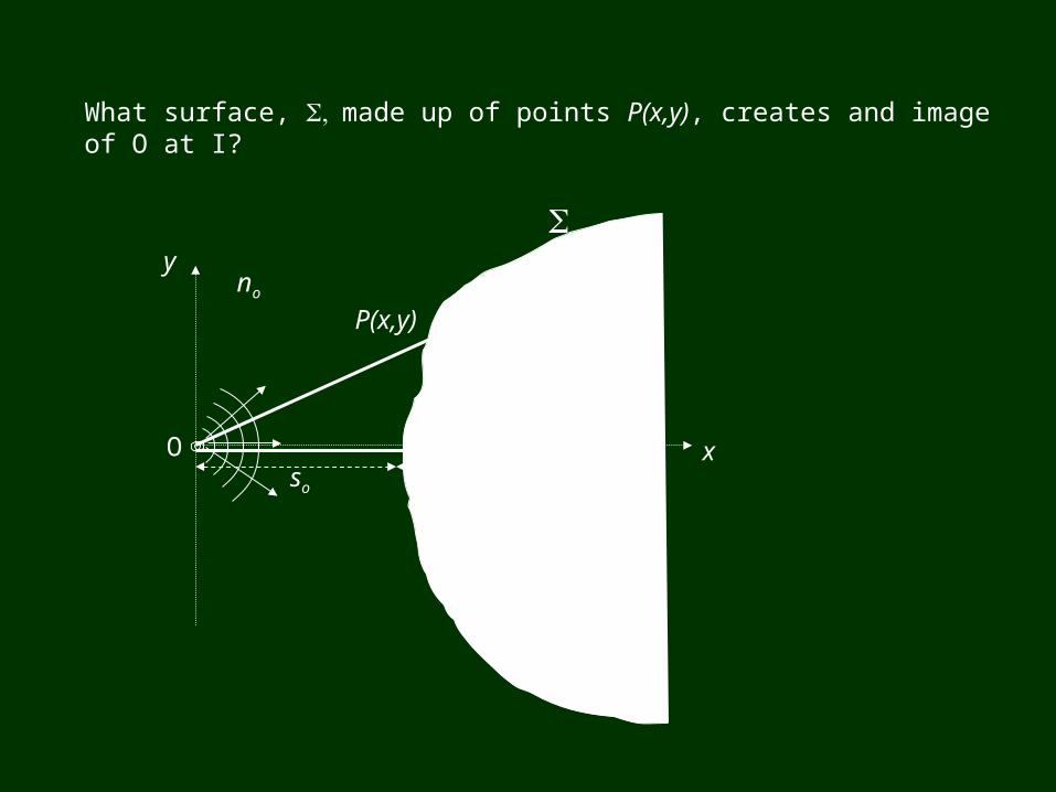
What surface, , S made up of points P(x,y), creates and image of O at I?
O
y
xso si
no ni
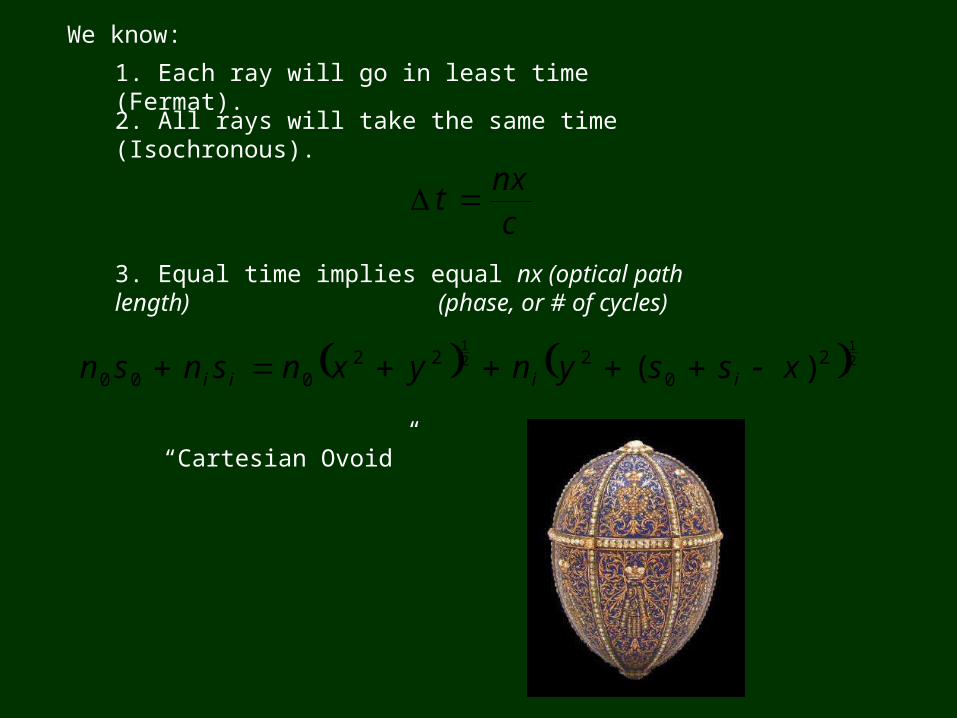
We know:
1. Each ray will go in least time (Fermat).
2. All rays will take the same time (Isochronous).
cnx
t
3. Equal time implies equal nx (optical path length)
2121
20
222000 )( xssynyxnsnsn iiii
“Cartesian Ovoid”
(phase, or # of cycles)
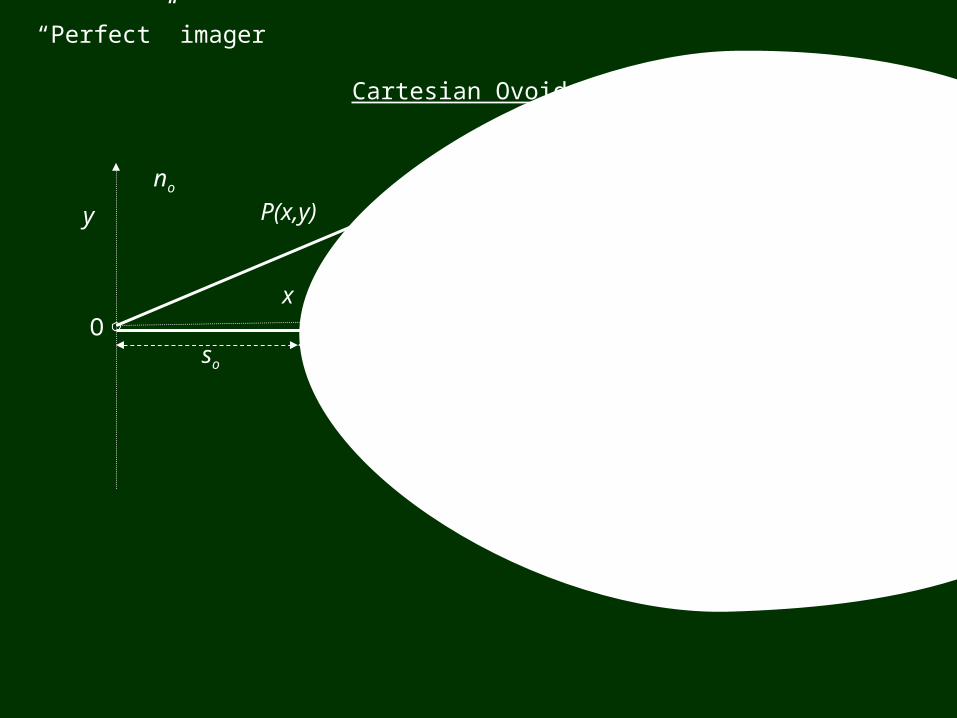
“Perfect” imager
I
P(x,y)
O
y
x
so si
no ni
Cartesian Ovoid
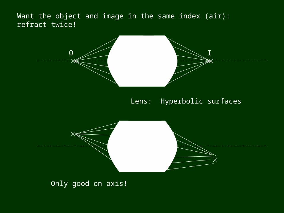
Want the object and image in the same index (air): refract twice!
O I
Lens: Hyperbolic surfaces
Only good on axis!
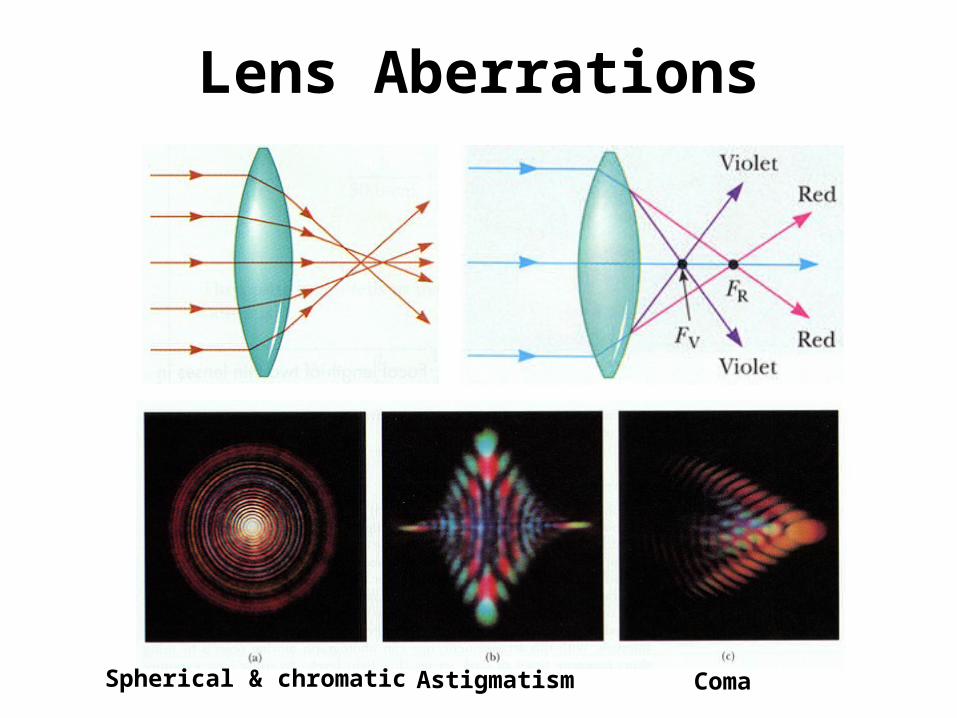
Lens Aberrations
Spherical & chromatic Astigmatism Coma
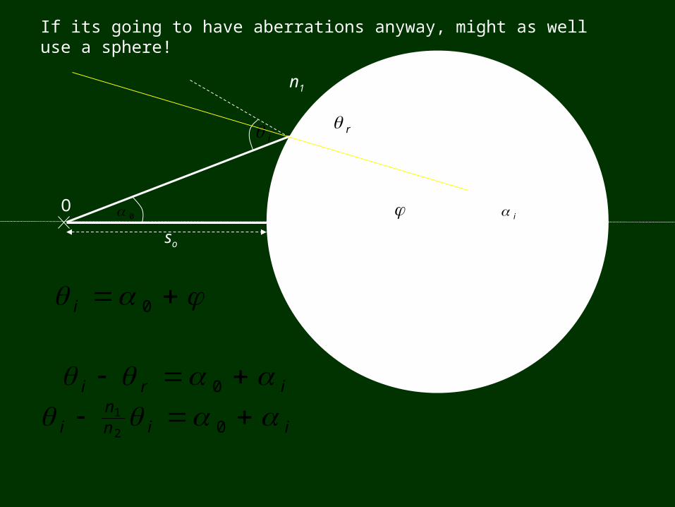
O I
so si
h R
0 i
n1 n2
i r
0i
iri 0
iinn
i 02
1
If its going to have aberrations anyway, might as well use a sphere!
inn 00 2
11
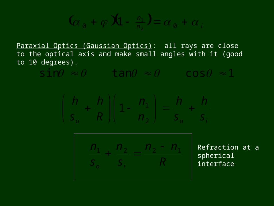
Paraxial Optics (Gaussian Optics): all rays are close to the optical axis and make small angles with it (good to 10 degrees).
sin tan 1cos
ioo sh
sh
nn
Rh
sh
2
11
Rnn
sn
sn
io
1221 Refraction at a spherical interface
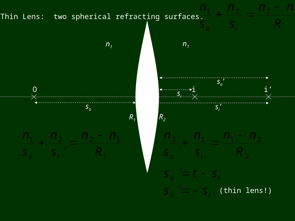
Thin Lens: two spherical refracting surfaces.
1
1221
' Rnn
sn
sn
io
O
so
n1 n2 n1
R1 R2
si’
i’
2
2112
' Rnn
sn
sn
io
so’
'' io sts '' io ss (thin lens!)
isi
Rnn
sn
sn
io
1221
2
21
1
1211
Rnn
Rnn
sn
sn
io
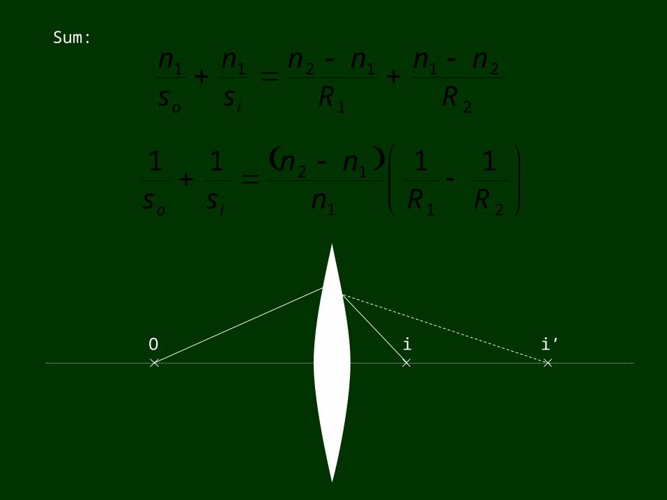
Sum:
211
12 1111RRn
nnss io
O i’i
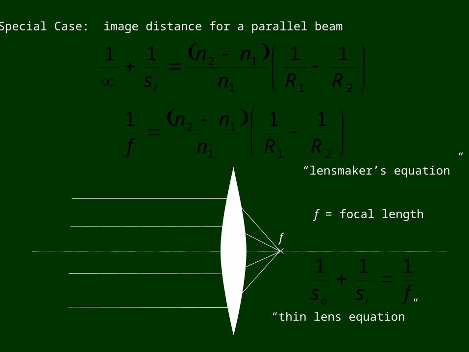
Special Case: image distance for a parallel beam
211
12 1111RRn
nnsi
f
211
12 111RRn
nnf
f = focal length
“lensmaker’s equation”
fss io
111
“thin lens equation”
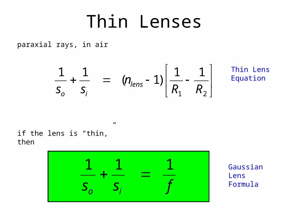
Thin Lenses
21
11)1(
11
RRn
ss lensio
fss io
111
paraxial rays, in air
if the lens is “thin,” then
Thin Lens Equation
Gaussian Lens Formula
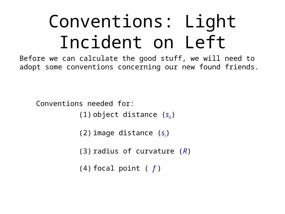
Conventions: Light Incident on Left
Before we can calculate the good stuff, we will need to adopt some conventions concerning our new found friends.
Conventions needed for:
(1) object distance (so)
(2) image distance (si)
(3) radius of curvature (R)
(4) focal point ( f )
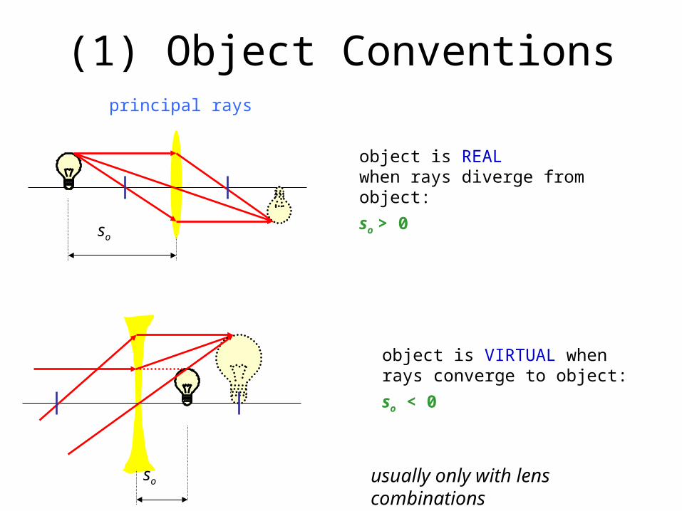
(1) Object Conventions
so
object is REAL when rays diverge from object:
so > 0
object is VIRTUAL when rays converge to object:
so < 0
usually only with lens combinations
so
principal rays
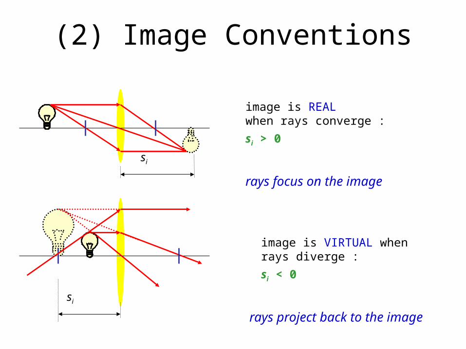
(2) Image Conventions
si
image is REAL when rays converge :
si > 0
image is VIRTUAL when rays diverge :
si < 0
rays project back to the image
si
rays focus on the image
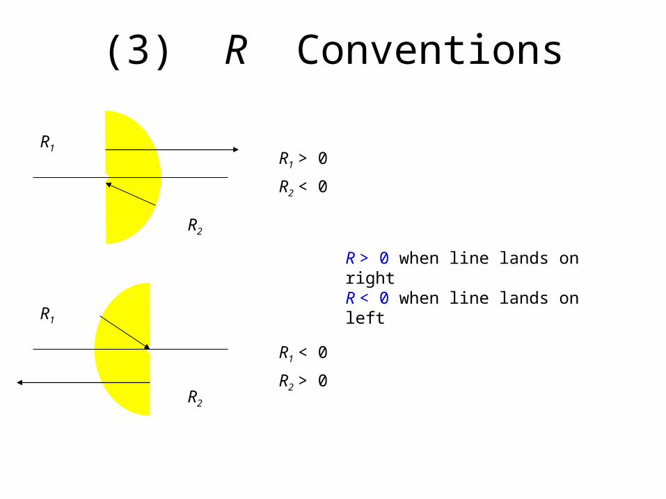
(3) R Conventions
R1
R2
R1
R2
R > 0 when line lands on right R < 0 when line lands on left
R1 > 0
R2 < 0
R1 < 0
R2 > 0
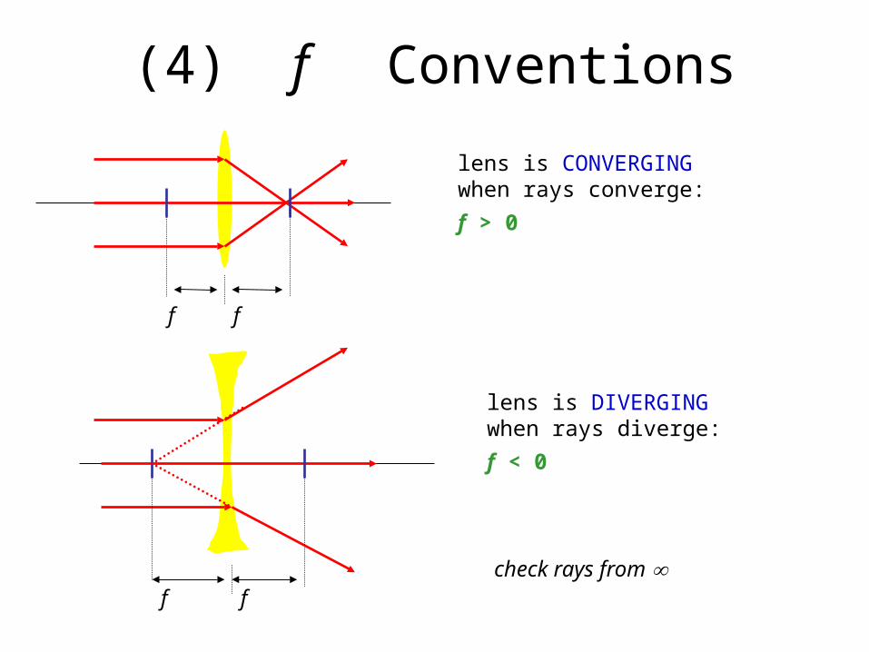
(4) f Conventions
f
lens is CONVERGING when rays converge:
f > 0
lens is DIVERGING when rays diverge:
f < 0
f
f fcheck rays from
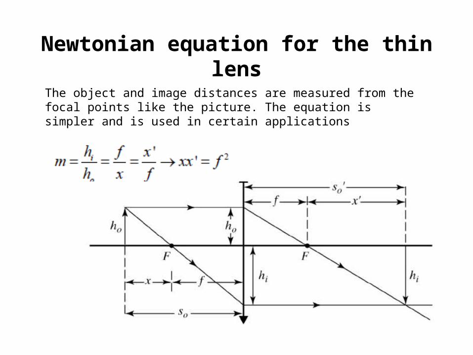
Newtonian equation for the thin lens
The object and image distances are measured from the focal points like the picture. The equation is simpler and is used in certain applications
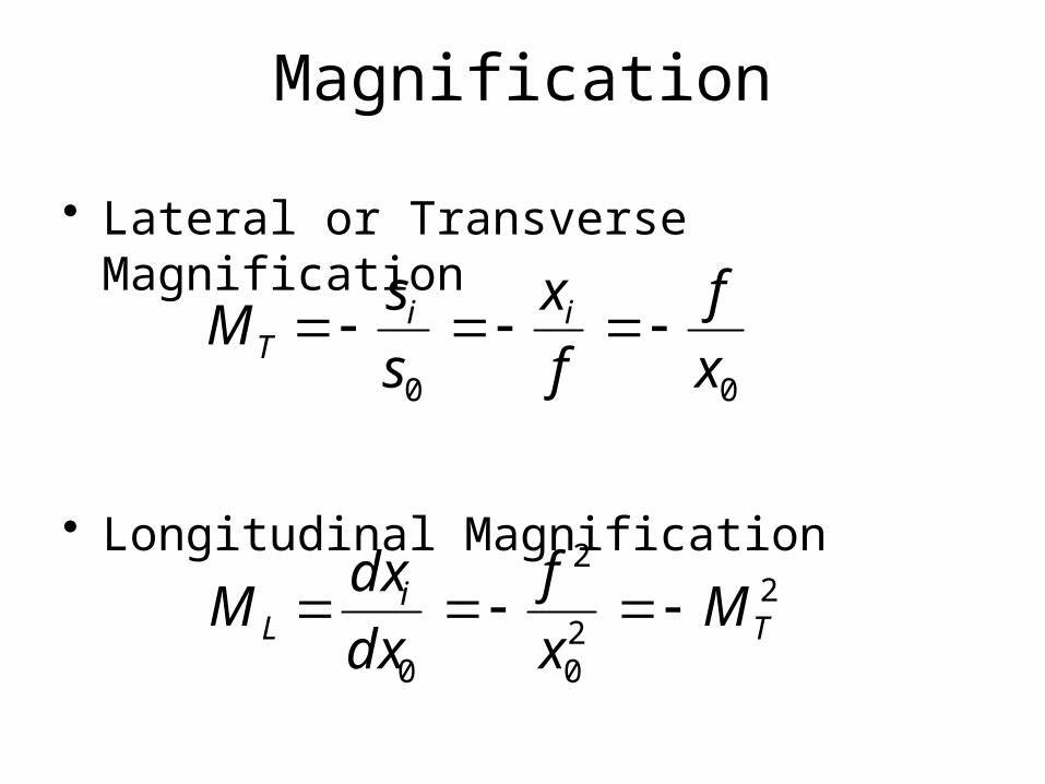
Magnification
• Lateral or Transverse Magnification
• Longitudinal Magnification
00 x
f
f
x
s
sM ii
T
220
2
0T
iL M
x
f
dx
dxM
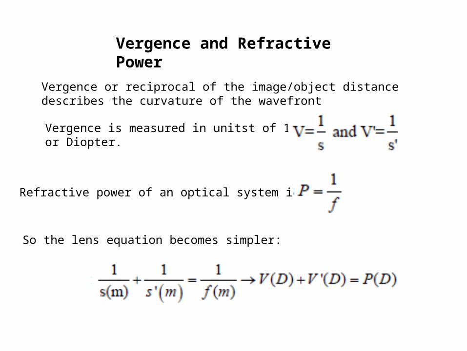
Vergence and Refractive Power
Vergence or reciprocal of the image/object distance describes the curvature of the wavefront
Vergence is measured in unitst of 1/m or Diopter.
Refractive power of an optical system is
So the lens equation becomes simpler:
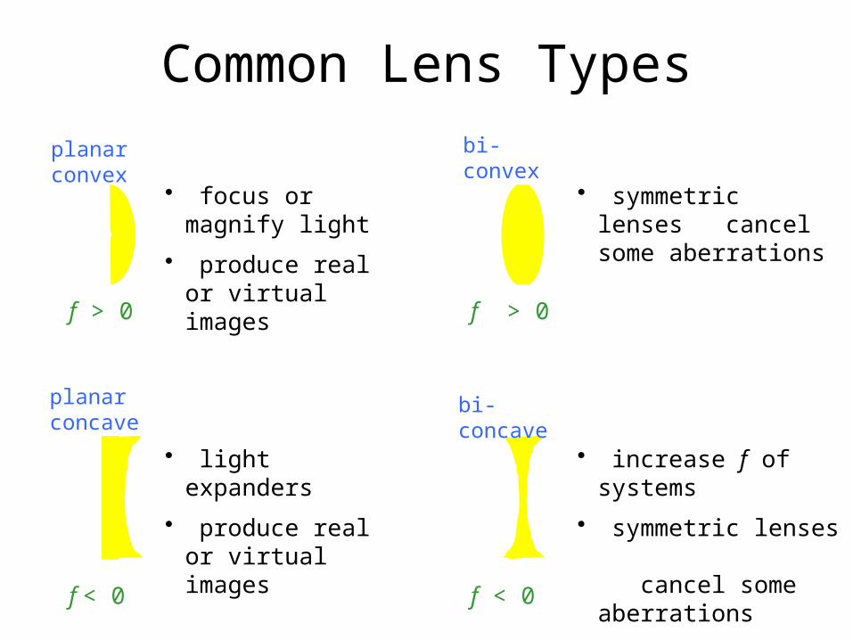
Common Lens Types
planar convex
f > 0 f > 0
bi-convex
bi-concave
f < 0 f < 0
planar concave
• symmetric lenses cancel
some aberrations
• increase f of systems
• symmetric lenses cancel some
aberrations
• focus or magnify light
• produce real or virtual images
• light expanders
• produce real or virtual images
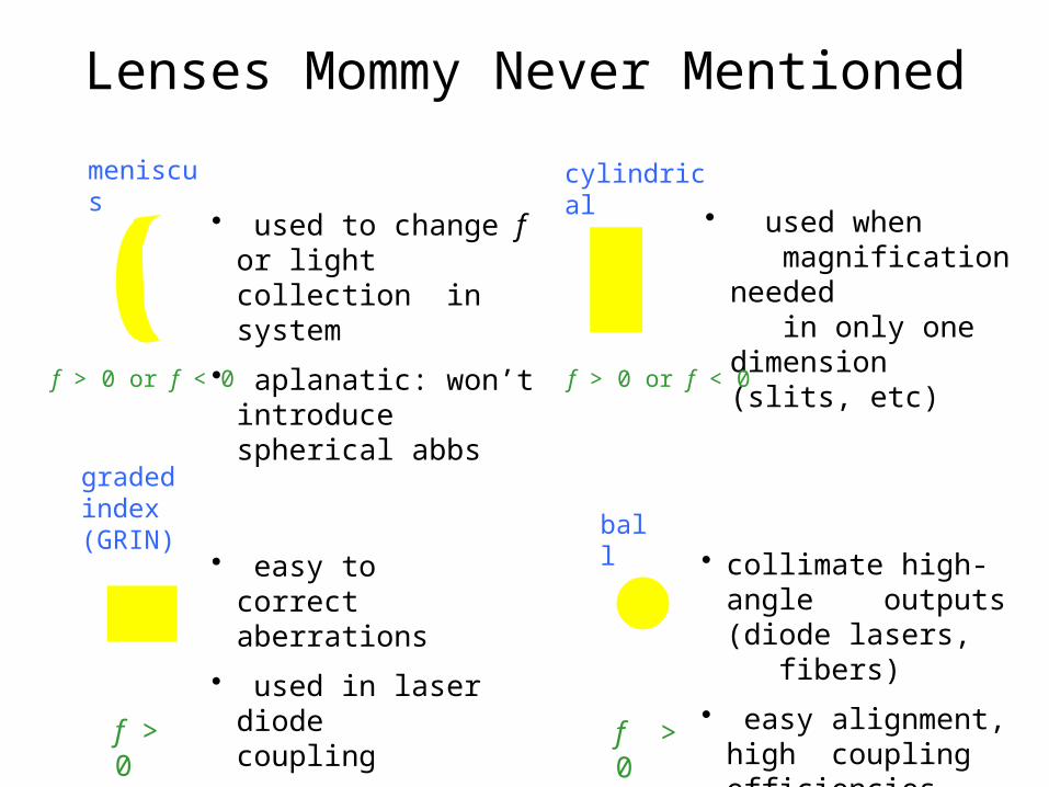
Lenses Mommy Never Mentioned
meniscus
f > 0
f > 0 or f < 0
cylindrical
ball
f > 0
graded index (GRIN)
• used when
magnification needed
in only one dimension (slits, etc)
• collimate high-angle outputs
(diode lasers, fibers)
• easy alignment, high coupling efficiencies
• used to change f or light collection
in system
• aplanatic: won’t introduce spherical abbs
• easy to correct
aberrations
• used in laser diode coupling
f > 0 or f < 0
Example
Locate the image of an object placed 1.2 m from the vertex of a gypsy’s crystal ball, which has a 20-cm diameter (n=1.5). Make a sketch of the thing (not the gypsy, the rays)

axis
Thin-Lens Combinations
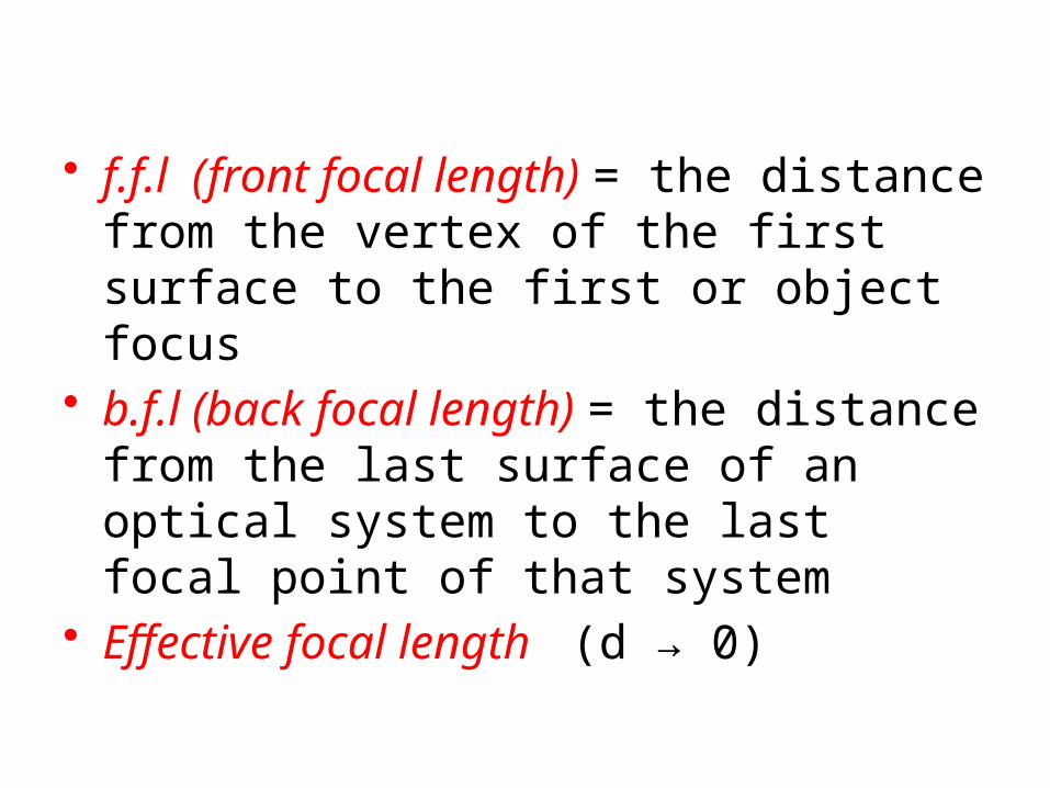
• f.f.l (front focal length) = the distance from the vertex of the first surface to the first or object focus
• b.f.l (back focal length) = the distance from the last surface of an optical system to the last focal point of that system
• Effective focal length (d → 0)
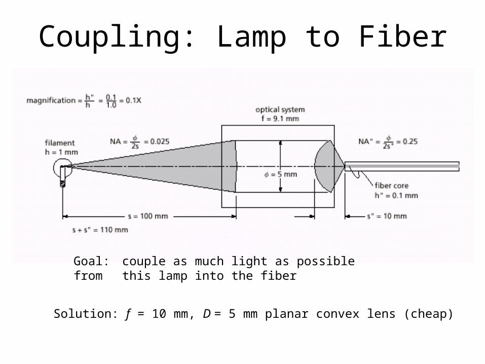
Coupling: Lamp to Fiber
Goal: couple as much light as possible from this lamp into the fiber
Solution: f = 10 mm, D = 5 mm planar convex lens (cheap)
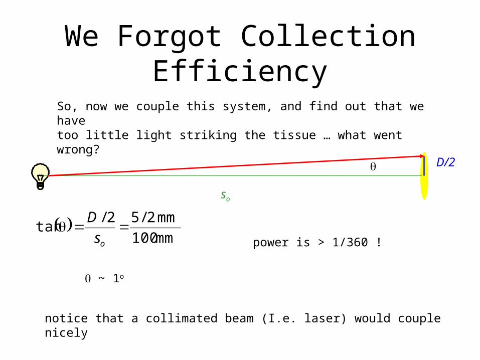
We Forgot Collection Efficiency
So, now we couple this system, and find out that we havetoo little light striking the tissue … what went wrong?
~ 1o
mm100
mm2/52/tan
os
D
power is > 1/360 !
so
D/2
notice that a collimated beam (I.e. laser) would couple nicely
The size of a lens determines its light gathering power and, consequently, the brightness of the image it forms. Two commonly used indicators of this special characteristic of a lens are called the f- number and the numerical aperture.
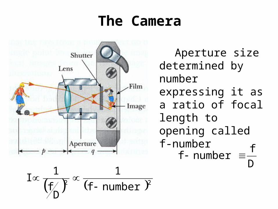
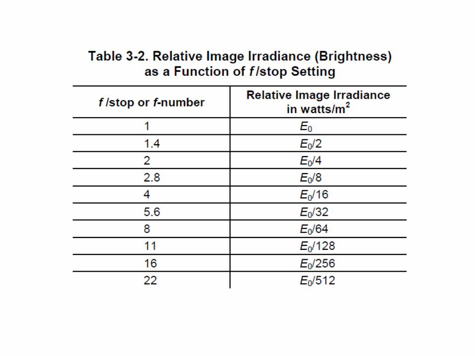
The Camera
Aperture size determined by number expressing it as a ratio of focal length to opening called f-number
Df
numberf
22 numberf
1
Df
1I
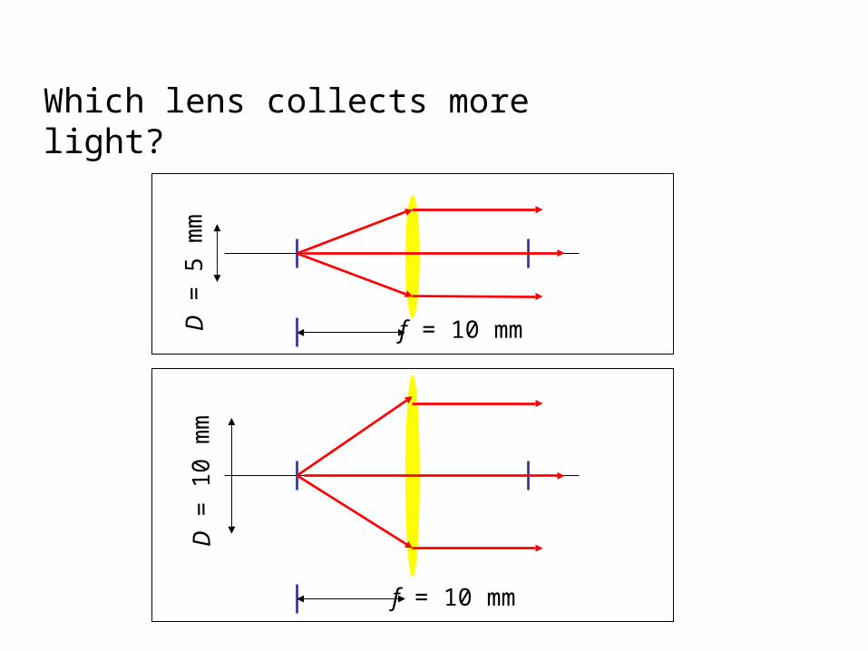
Which lens collects more light?
D =
5 m
mD
= 1
0 m
m
f = 10 mm
f = 10 mm
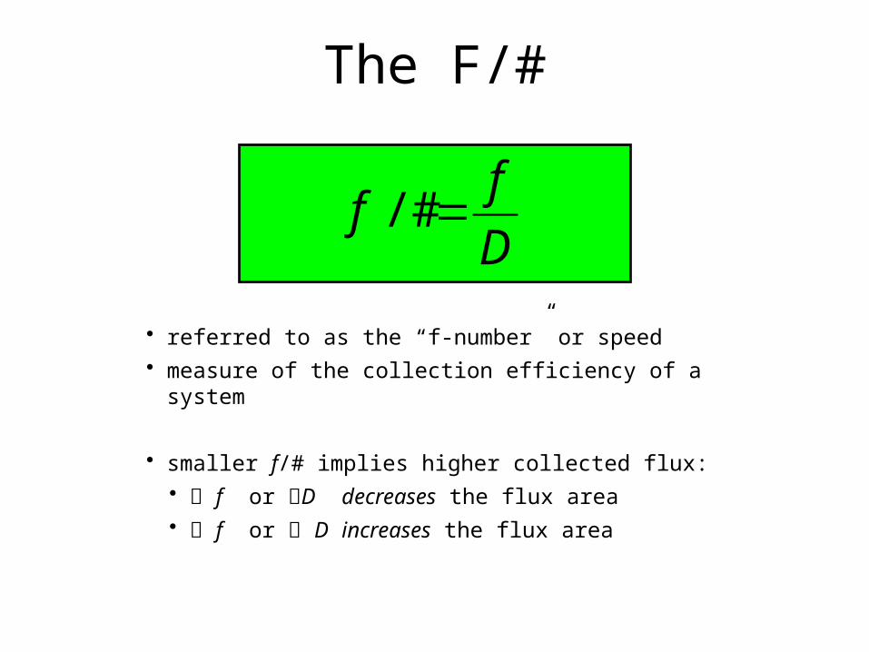
The F/#
D
ff /#
• referred to as the “f-number” or speed• measure of the collection efficiency of a system
• smaller f/# implies higher collected flux:• f or D decreases the flux area• f or D increases the flux area
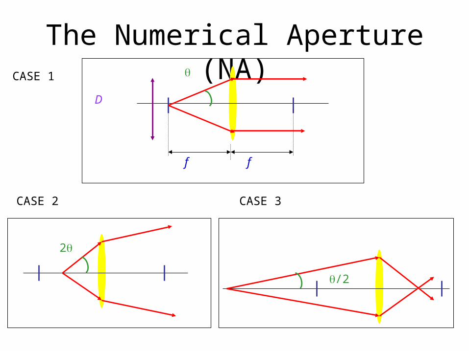
The Numerical Aperture (NA)
/2
2
f f
D
CASE 1
CASE 2 CASE 3
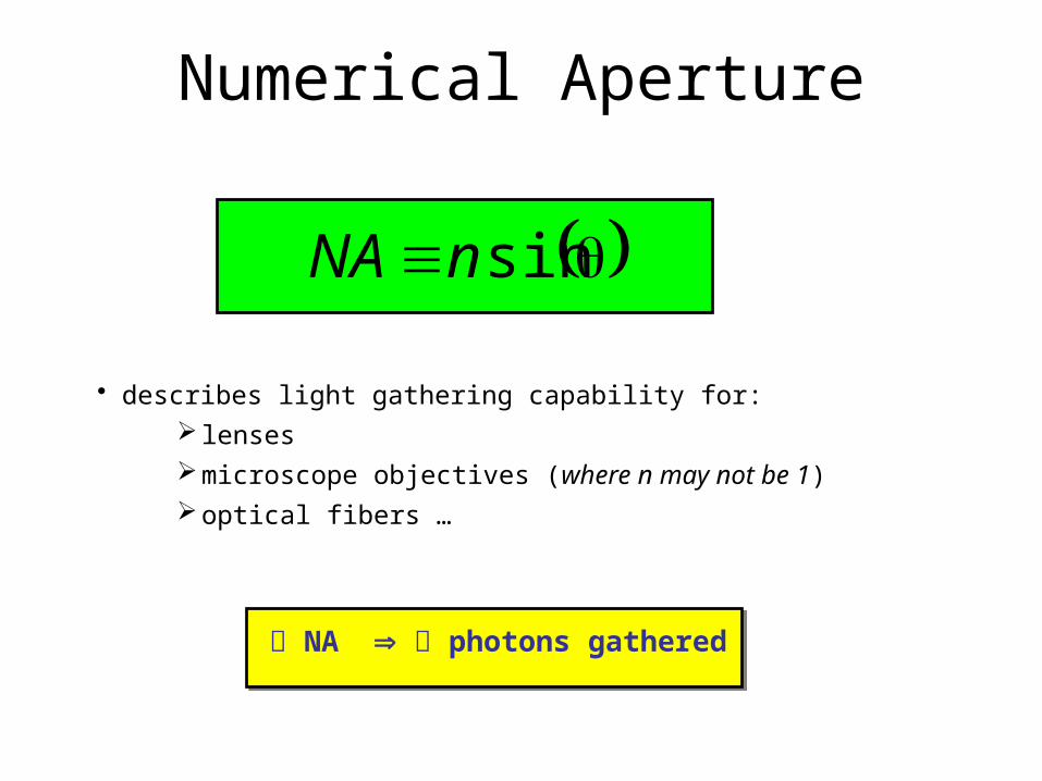
Numerical Aperture
sinnNA
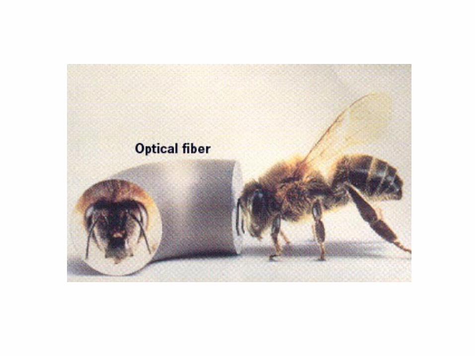
• describes light gathering capability for: lensesmicroscope objectives (where n may not be 1)optical fibers …
NA photons gathered
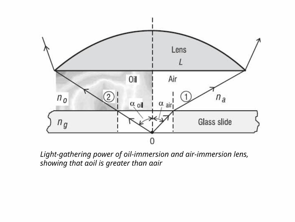
Light-gathering power of oil-immersion and air-immersion lens, showing that αoil is greater than αair
In summary, one can increase the light-gathering power of a lens and the brightness of the image formed by a lens by decreasing the f-number of the lens (increasing lens diameter) or by increasing the numerical aperture of the lens (increasing the refraction index and thus making possible a larger acceptance angle).

IMAGE FORMATION WITH MIRRORS
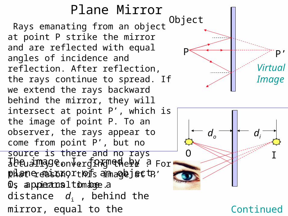
Plane Mirror Rays emanating from an object at point P strike the mirror and are reflected with equal angles of incidence and reflection. After reflection, the rays continue to spread. If we extend the rays backward behind the mirror, they will intersect at point P’, which is the image of point P. To an observer, the rays appear to come from point P’, but no source is there and no rays actually converging there . For that reason, this image at P’ is a virtual image.
Object
Virtual Image
P P’
O I
do di
The image, I, formed by a plane mirror of an object, O, appears to be a distance di , behind the mirror, equal to the object distance do. Continued
…
Object Image
P B
M
P’do di
h h’
Mirror
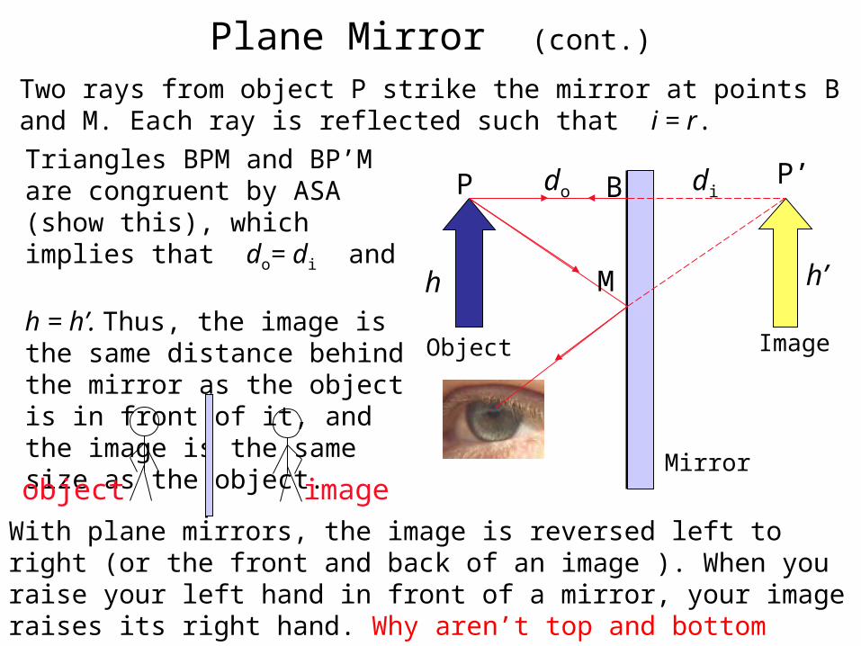
Two rays from object P strike the mirror at points B and M. Each ray is reflected such that i = r.
Triangles BPM and BP’M are congruent by ASA (show this), which implies that do= di and h = h’. Thus, the image is the same distance behind the mirror as the object is in front of it, and the image is the same size as the object.
With plane mirrors, the image is reversed left to right (or the front and back of an image ). When you raise your left hand in front of a mirror, your image raises its right hand. Why aren’t top and bottom reversed?
object image
Plane Mirror (cont.)
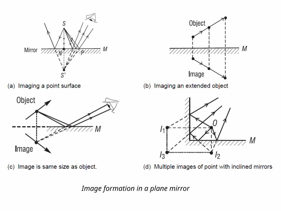
Image formation in a plane mirror
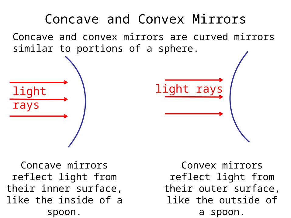
Concave and Convex MirrorsConcave and convex mirrors are curved mirrors similar to portions of a sphere.
light rays
light rays
Concave mirrors reflect light from their inner
surface, like the inside of a spoon.
Convex mirrors reflect light from their outer
surface, like the outside of a spoon.
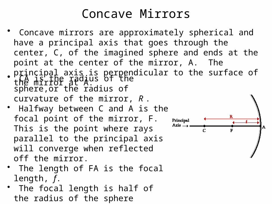
Concave Mirrors• Concave mirrors are approximately spherical and have a
principal axis that goes through the center, C, of the imagined sphere and ends at the point at the center of the mirror, A. The principal axis is perpendicular to the surface of the mirror at A.• CA is the radius of the sphere,or the radius of curvature of the mirror, R .
• Halfway between C and A is the focal point of the mirror, F. This is the point where rays parallel to the principal axis will converge when reflected off the mirror.
• The length of FA is the focal length, f.
• The focal length is half of the radius of the sphere (proven on next slide).
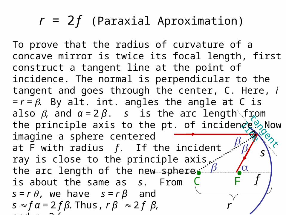
r = 2 f (Paraxial Aproximation)
• •
C F
r
f
s
To prove that the radius of curvature of a concave mirror is twice its focal length, first construct a tangent line at the point of incidence. The normal is perpendicular to the tangent and goes through the center, C. Here, i = r = . By alt. int. angles the angle at C is also , and α = 2 β. s is the arc length from the principle axis to the pt. of incidence. Now imagine a sphere centered at F with radius f. If the incident ray is close to the principle axis, the arc length of the new sphere is about the same as s. From s = r , we have s = r β and s f α = 2 f β. Thus, r β 2 f β, and r = 2 f.
tangent
line
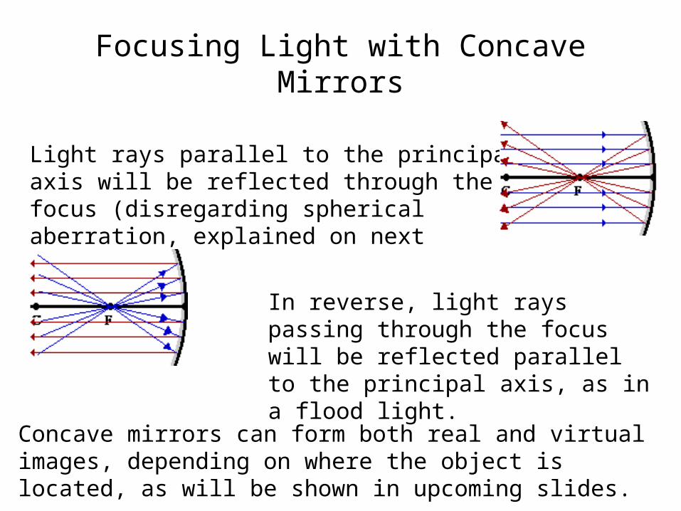
Focusing Light with Concave Mirrors
Light rays parallel to the principal axis will be reflected through the focus (disregarding spherical aberration, explained on next slide.)
In reverse, light rays passing through the focus will be reflected parallel to the principal axis, as in a flood light.
Concave mirrors can form both real and virtual images, depending on where the object is located, as will be shown in upcoming slides.
••CF • •C
F
Spherical Mirror Parabolic Mirror
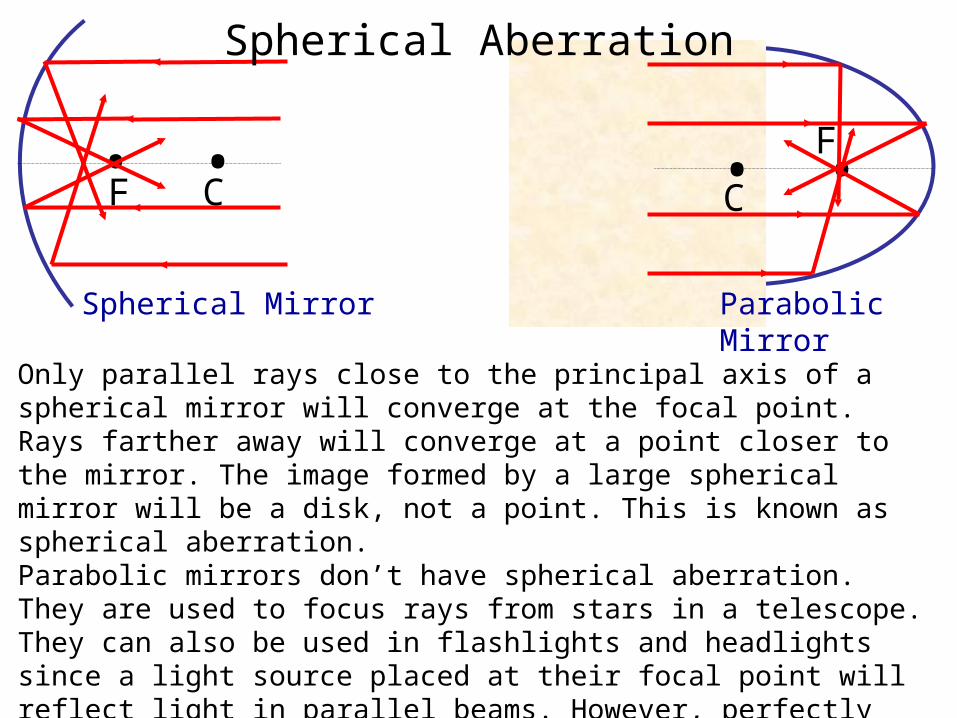
Only parallel rays close to the principal axis of a spherical mirror will converge at the focal point. Rays farther away will converge at a point closer to the mirror. The image formed by a large spherical mirror will be a disk, not a point. This is known as spherical aberration. Parabolic mirrors don’t have spherical aberration. They are used to focus rays from stars in a telescope. They can also be used in flashlights and headlights since a light source placed at their focal point will reflect light in parallel beams. However, perfectly parabolic mirrors are hard to make and slight errors could lead to spherical aberration. Continued…
Spherical Aberration
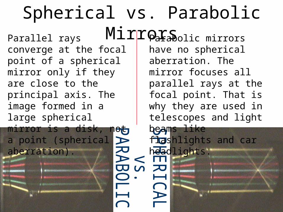
Spherical vs. Parabolic MirrorsParallel rays converge at the focal point of a spherical mirror only if they are close to the principal axis. The image formed in a large spherical mirror is a disk, not a point (spherical aberration).
Parabolic mirrors have no spherical aberration. The mirror focuses all parallel rays at the focal point. That is why they are used in telescopes and light beams like flashlights and car headlights.
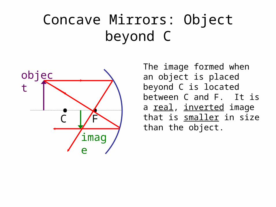
Concave Mirrors: Object beyond C
• •C F
object
image
The image formed when an object is placed beyond C is located between C and F. It is a real, inverted image that is smaller in size than the object.
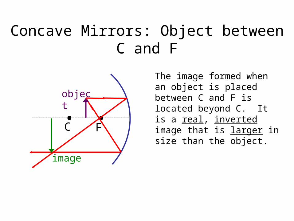
Concave Mirrors: Object between C and F
• •C F
object
image
The image formed when an object is placed between C and F is located beyond C. It is a real, inverted image that is larger in size than the object.
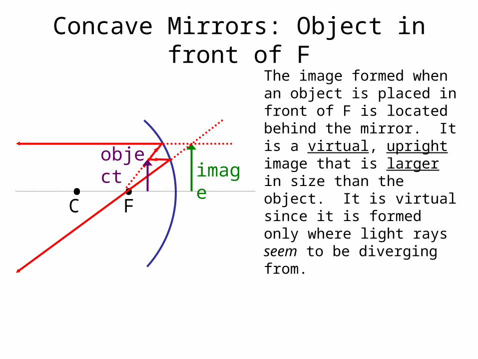
Concave Mirrors: Object in front of F
• •C F
object imag
e
The image formed when an object is placed in front of F is located behind the mirror. It is a virtual, upright image that is larger in size than the object. It is virtual since it is formed only where light rays seem to be diverging from.
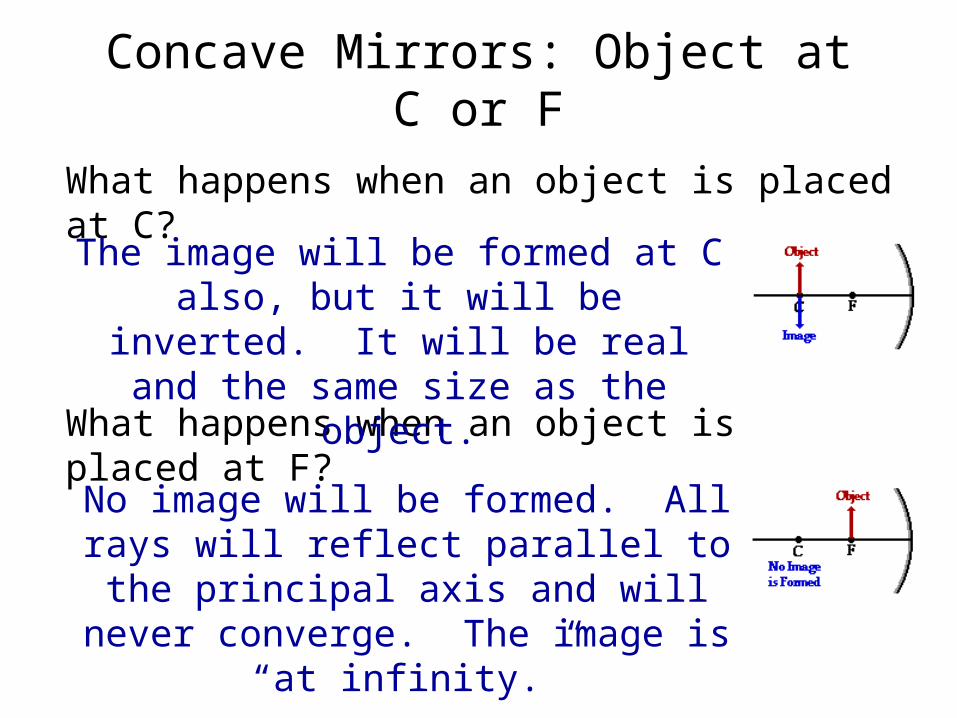
Concave Mirrors: Object at C or F
What happens when an object is placed at C?
What happens when an object is placed at F?
The image will be formed at C also, but it will be inverted. It will be real and the same size as the
object.
No image will be formed. All rays will reflect parallel to the principal axis and will never converge. The
image is “at infinity.”
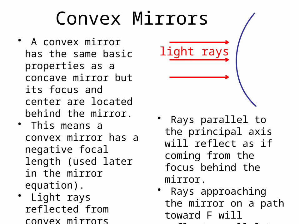
Convex Mirrors• A convex mirror has
the same basic properties as a concave mirror but its focus and center are located behind the mirror.
• This means a convex mirror has a negative focal length (used later in the mirror equation).
• Light rays reflected from convex mirrors always diverge, so only virtual images will be formed.
light rays
• Rays parallel to the principal axis will reflect as if coming from the focus behind the mirror.
• Rays approaching the mirror on a path toward F will reflect parallel to the principal axis.
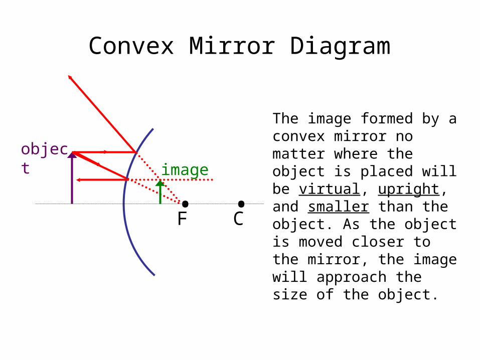
Convex Mirror Diagram
• •CF
objectimage
The image formed by a convex mirror no matter where the object is placed will be virtual, upright, and smaller than the object. As the object is moved closer to the mirror, the image will approach the size of the object.
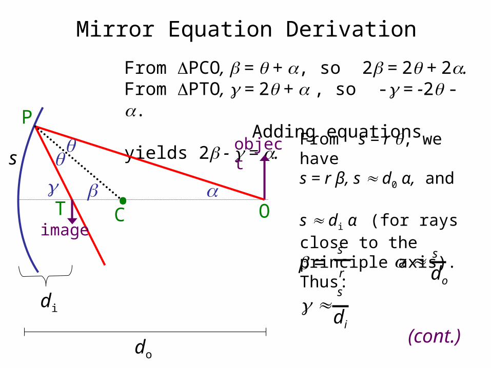
Mirror Equation Derivation
From PCO, = + , so 2 = 2 + 2. From PTO, = 2 + , so - = -2 - . Adding equations yields 2 - = .
=s
r
s
di
s
do
(cont.)
•C
s
object
image
di
O
P
T
From s = r , we have s = r β, s d0 α, and s di α (for rays close to the principle axis). Thus:
do
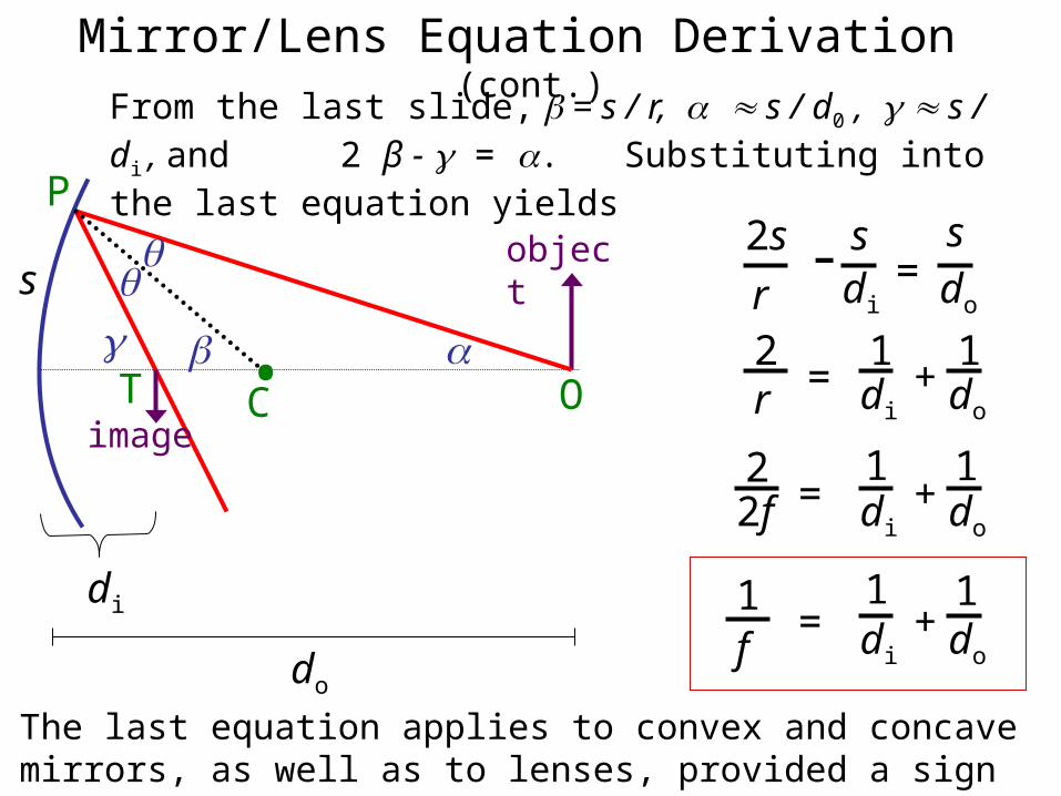
Mirror/Lens Equation Derivation (cont.)
2s
r- s
di=
sdo
1do
2r =
1di
+
22f =
1do
1di
+
1f
=1do
1di
+
From the last slide, = s / r, s / d0 , s / di , and 2 β - = . Substituting into the last equation yields
•C
s
object
image
di
do
O
P
T
The last equation applies to convex and concave mirrors, as well as to lenses, provided a sign convention is adhered to.
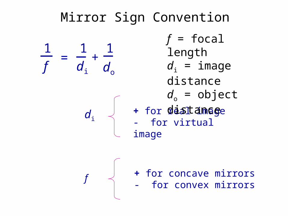
Mirror Sign Convention
+ for real image- for virtual image
+ for concave mirrors- for convex mirrors
1f
=1
do
1di
+
f = focal lengthdi = image distancedo = object distance
di
f
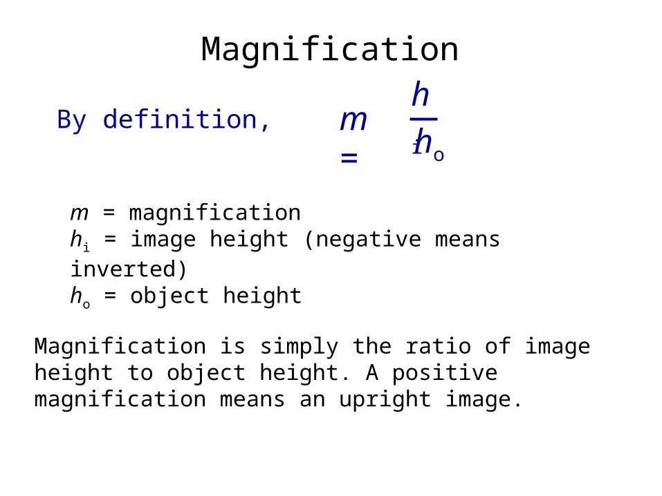
Magnification
m = magnificationhi = image height (negative means inverted)ho = object height
m = hi
ho
By definition,
Magnification is simply the ratio of image height to object height. A positive magnification means an upright image.
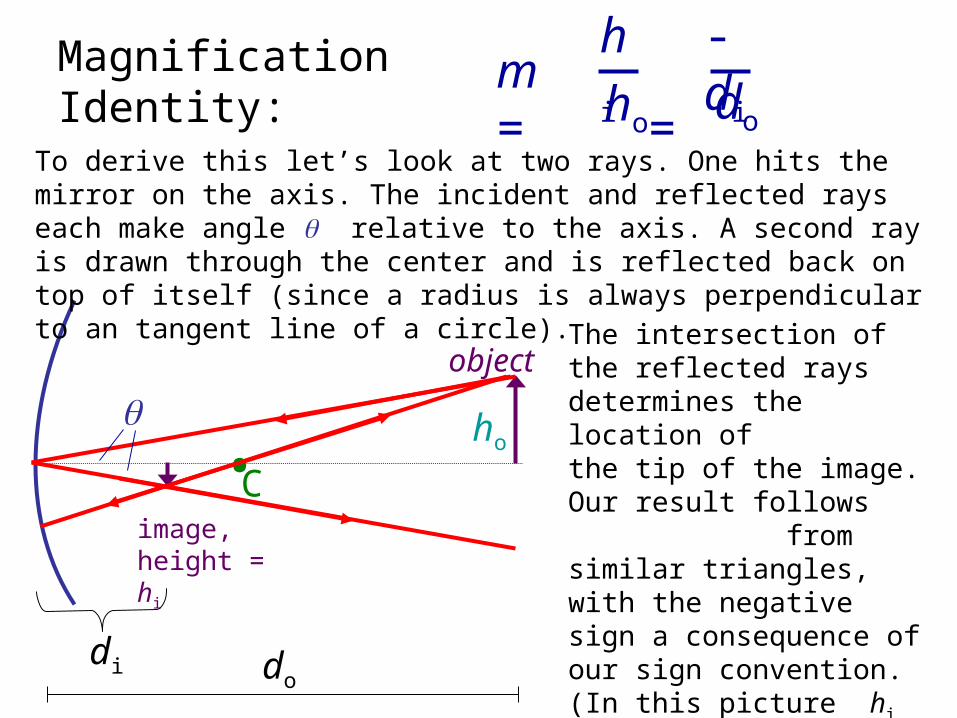
Magnification Identity:
m = -di
do
hi
ho
=
•C
object
image, height = hi
di do
To derive this let’s look at two rays. One hits the mirror on the axis. The incident and reflected rays each make angle relative to the axis. A second ray is drawn through the center and is reflected back on top of itself (since a radius is always perpendicular to an tangent line of a circle).
ho
The intersection of the reflected raysdetermines the location of the tip of the image. Our result follows from similar triangles, with the negative sign a consequence of our sign convention. (In this picture hi is negative and di is positive.)
Example
Looking into the bowl of a soupspoon, a man standing 25 cm away sees his image reflected with a magnification of -0.064. Determine the radius of curvature of the spoon.
Complex System (Lenses-Mirrors)
OPTICAL DEVICES
Optical defects and correction
Myopia (nearsightedness)
Hypermetropia (farsightedness)
Astigmatism
Presbyopia
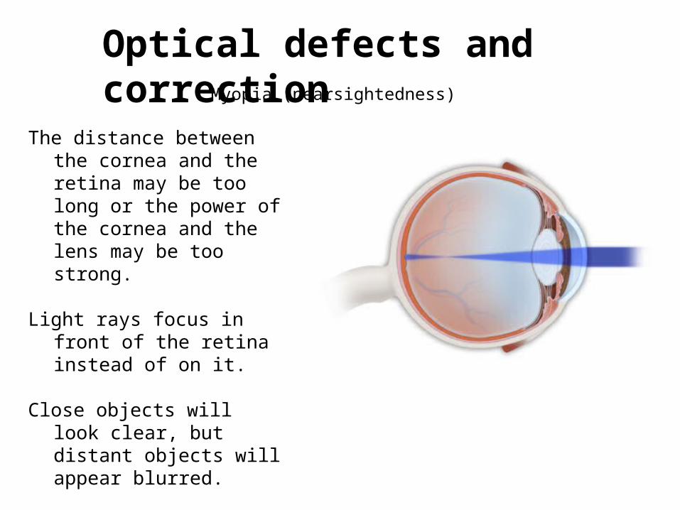
Optical defects and correctionMyopia (nearsightedness)
The distance between the cornea and the retina may be too long or the power of the cornea and the lens may be too strong.
Light rays focus in front of the retina instead of on it.
Close objects will look clear, but distant objects will appear blurred.
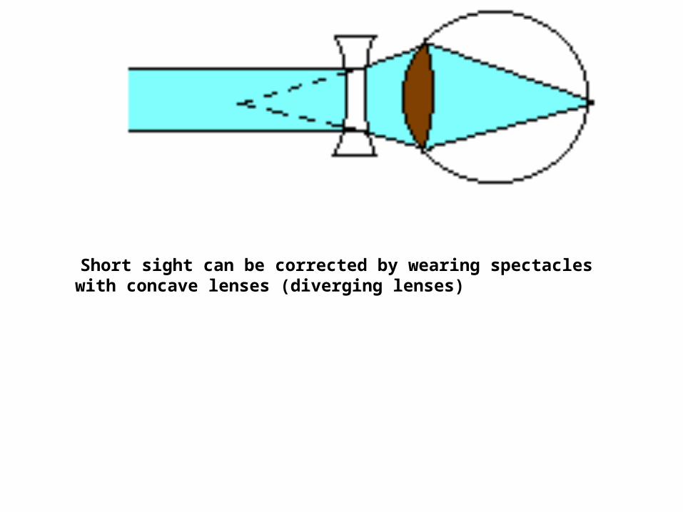
Short sight can be corrected by wearing spectacles with concave lenses (diverging lenses)
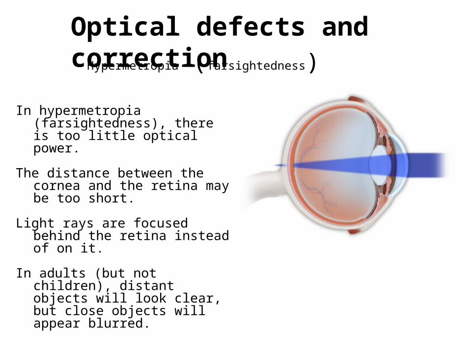
Optical defects and correctionHypermetropia (farsightedness)
In hypermetropia (farsightedness), there is too little optical power.
The distance between the cornea and the retina may be too short.
Light rays are focused behind the retina instead of on it.
In adults (but not children), distant objects will look clear, but close objects will appear blurred.
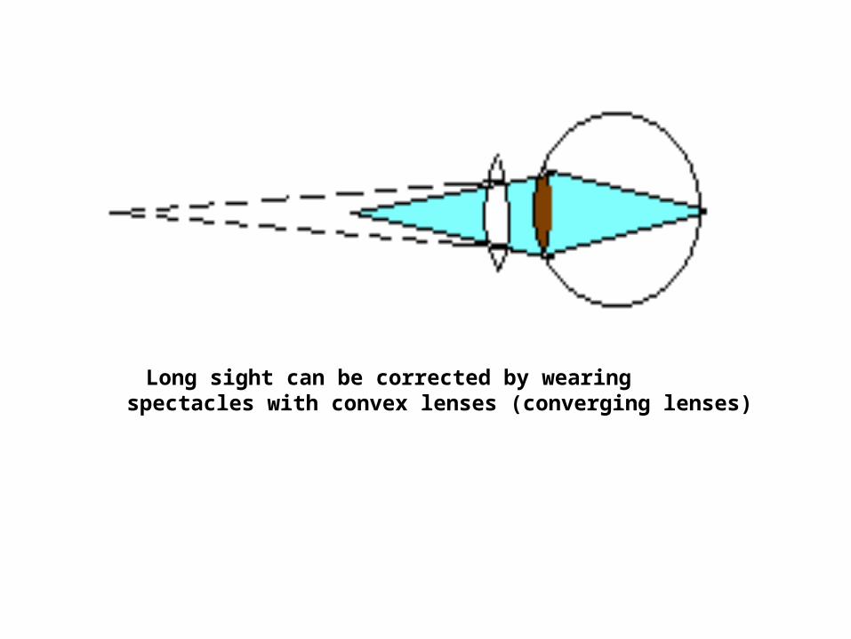
Long sight can be corrected by wearing spectacles with convex lenses (converging lenses)
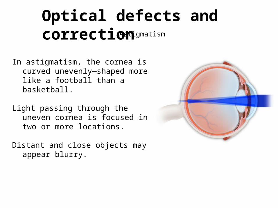
Optical defects and correctionAstigmatism
In astigmatism, the cornea is curved unevenly—shaped more like a football than a basketball.
Light passing through the uneven cornea is focused in two or more locations.
Distant and close objects may appear blurry.
Presbyopia
Optical defects and correction
Presbyopia = short arm syndrome
Caused by ageing, people find it difficult to read small words at close distance
People also find it difficult to perform near work, such as embroidery or handwriting.
Correction most common by bifocal lenses
7.4 Thick lens*
Thick lenses are similar to the thin lenses and they also contain two systems of coaxial spherical surfaces. The difference between them is that thickness of the thick lenses cannot be negligible while the thickness of thin lenses can be ignored. As before, such a system can be solved by spherical surface, but it contain a lot of trivial details especially for coaxial optical system of more spherical surfaces.
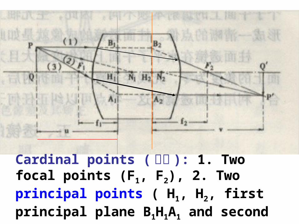
Cardinal points (基点 ): 1. Two focal points (F1, F2), 2. Two principal points ( H1, H2, first principal plane B1H1A1 and second principal plane B2H2A2), 3. Two nodes (N1, N2).
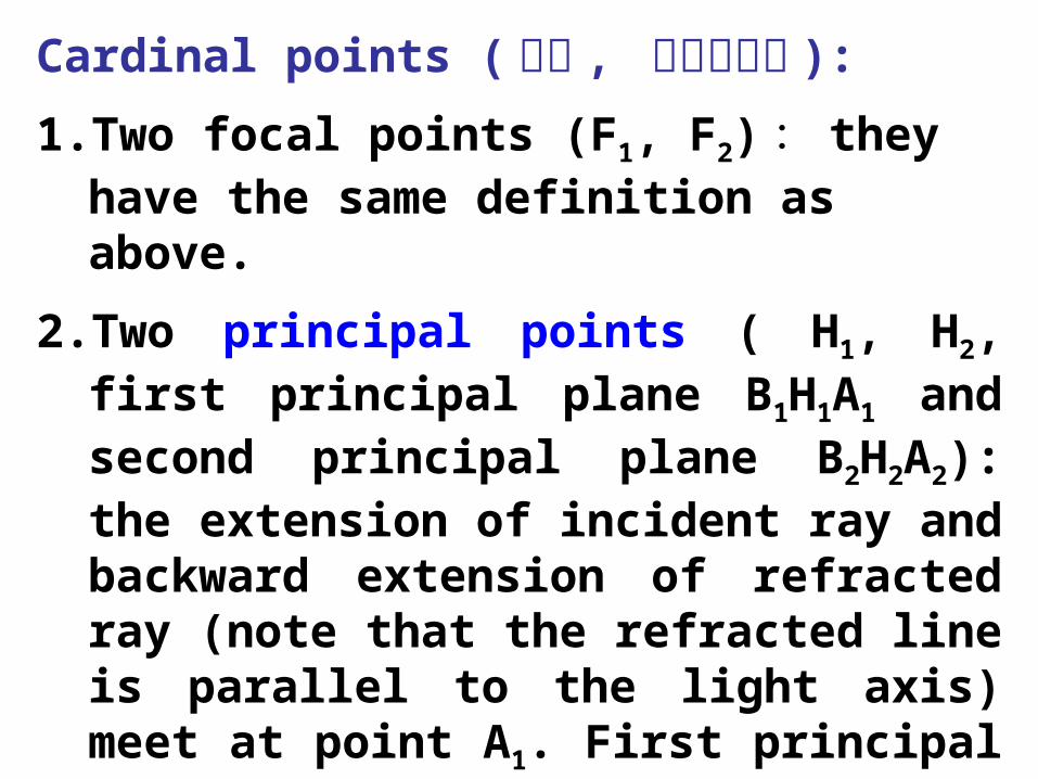
Cardinal points (基点 , 最重要的点 ):
1.Two focal points (F1, F2): they have the same definition as above.
2.Two principal points ( H1, H2, first principal plane B1H1A1 and second principal plane B2H2A2): the extension of incident ray and backward extension of refracted ray (note that the refracted line is parallel to the light axis) meet at point A1. First principal plane…
3.Two nodes (N1, N2), through these points, the incident line and refractive line are parallel.
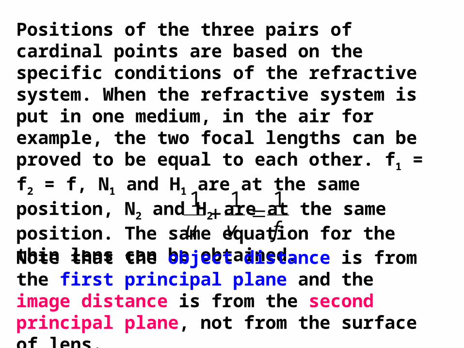
Positions of the three pairs of cardinal points are based on the specific conditions of the refractive system. When the refractive system is put in one medium, in the air for example, the two focal lengths can be proved to be equal to each other. f1 = f2 = f, N1 and H1 are at the same position, N2 and H2 are at the same position. The same equation for the thin lens can be obtained.fvu
111
Note that the object distance is from the first principal plane and the image distance is from the second principal plane, not from the surface of lens.

Complex optical systems
Thick lenses, combinations of lenses etc..
t
nL
n n’
Consider case where t is not negligible.
We would like to maintain our Gaussian imaging relation
Ps
n
s
n'
'
But where do we measure s, s’ ; f, f’ from? How do we determine P?
We try to develop a formalism that can be used with any system!!
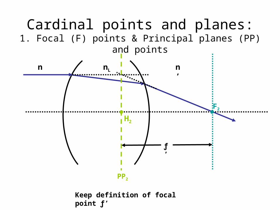
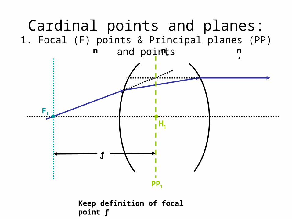
Cardinal points and planes:1. Focal (F) points & Principal planes (PP) and points
nLn n’
Keep definition of focal point ƒ’
H2
ƒ’
F2
PP2
Cardinal points and planes:1. Focal (F) points & Principal planes (PP) and points
nLn n’
Keep definition of focal point ƒ
H1
ƒ
F1
PP1
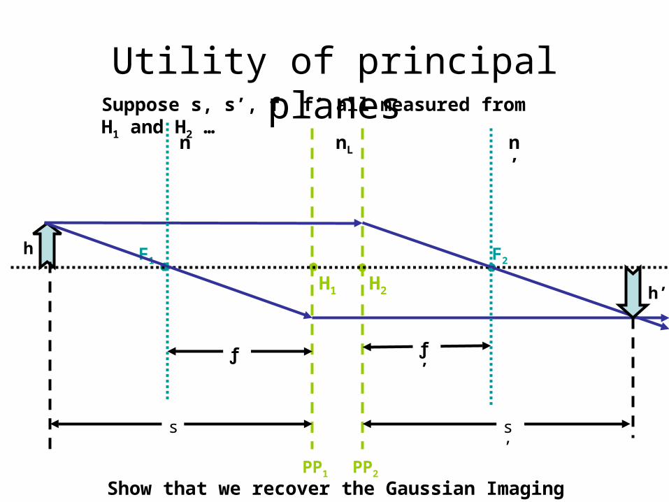
Utility of principal planes
H2
ƒ’
F2
PP2
H1
ƒ
F1
PP1
s s’
nLn n’
h
h’
Suppose s, s’, f, f’ all measured from H1 and H2 …
Show that we recover the Gaussian Imaging relation…
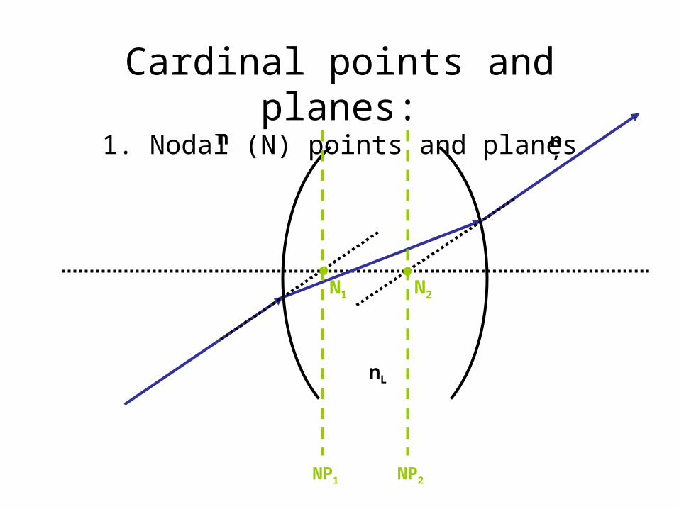
Cardinal points and planes:1. Nodal (N) points and planes
n n’
N2
NP2
N1
NP1
nL
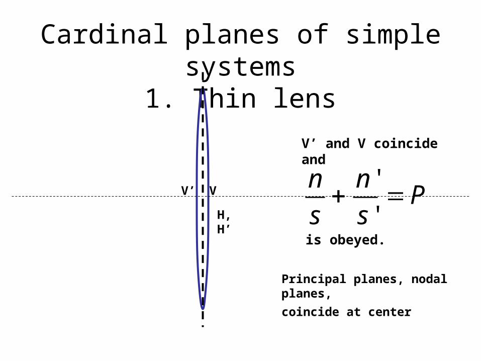
Cardinal planes of simple systems1. Thin lens
Ps
n
s
n'
'
Principal planes, nodal planes,
coincide at center
V
H, H’
V’
V’ and V coincide and
is obeyed.
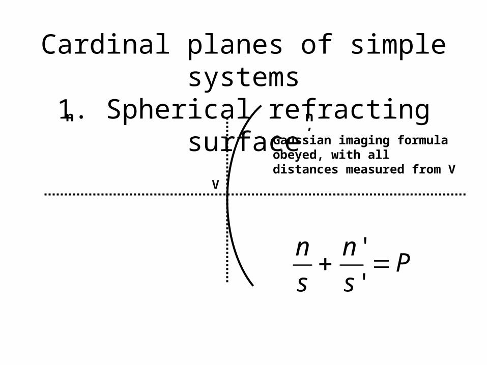
Cardinal planes of simple systems1. Spherical refracting surfacen n’
Gaussian imaging formula obeyed, with all distances measured from V
V
Ps
n
s
n'
'
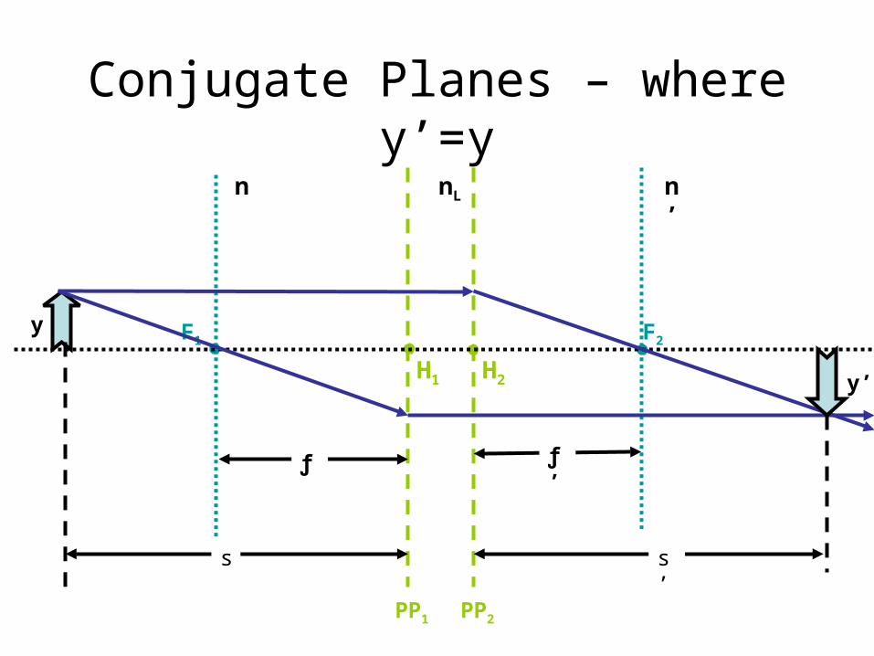
Conjugate Planes – where y’=y
H2
ƒ’
F2
PP2
H1
ƒ
F1
PP1
s s’
nLn n’
y
y’
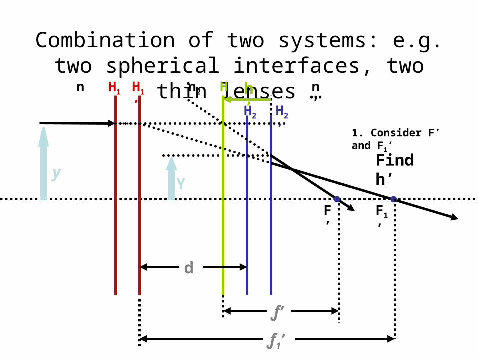
Combination of two systems: e.g. two spherical interfaces, two thin lenses …
n2
n n’H1
’H1
H2 H2
’
H’
yY
d
ƒ’
ƒ1’
F’ F1
’
1. Consider F’ and F1’
h’
Find h’
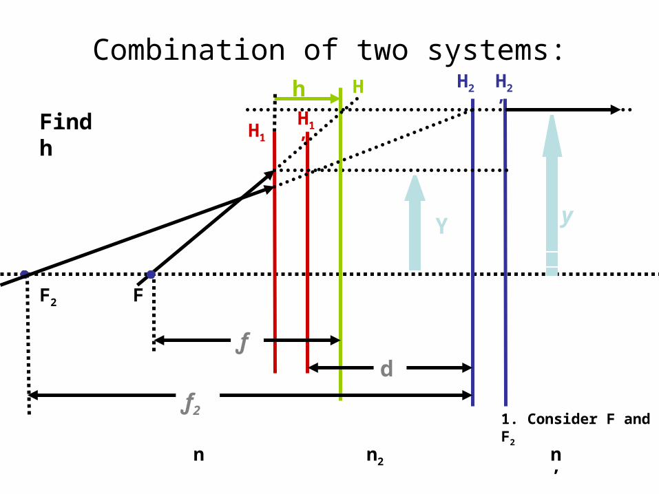
Combination of two systems:
n2
n n’
H1
’H1
H2 H2
’H
yY
dƒ
1. Consider F and F2
F2
ƒ2
h
F
Find h
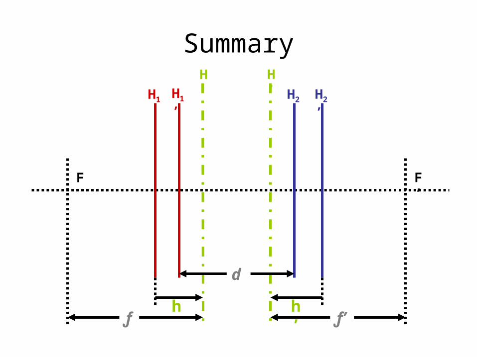
Summary
H1
’H1 H2 H2
’
H H’
ƒ ƒ’h h
’
F F’
d
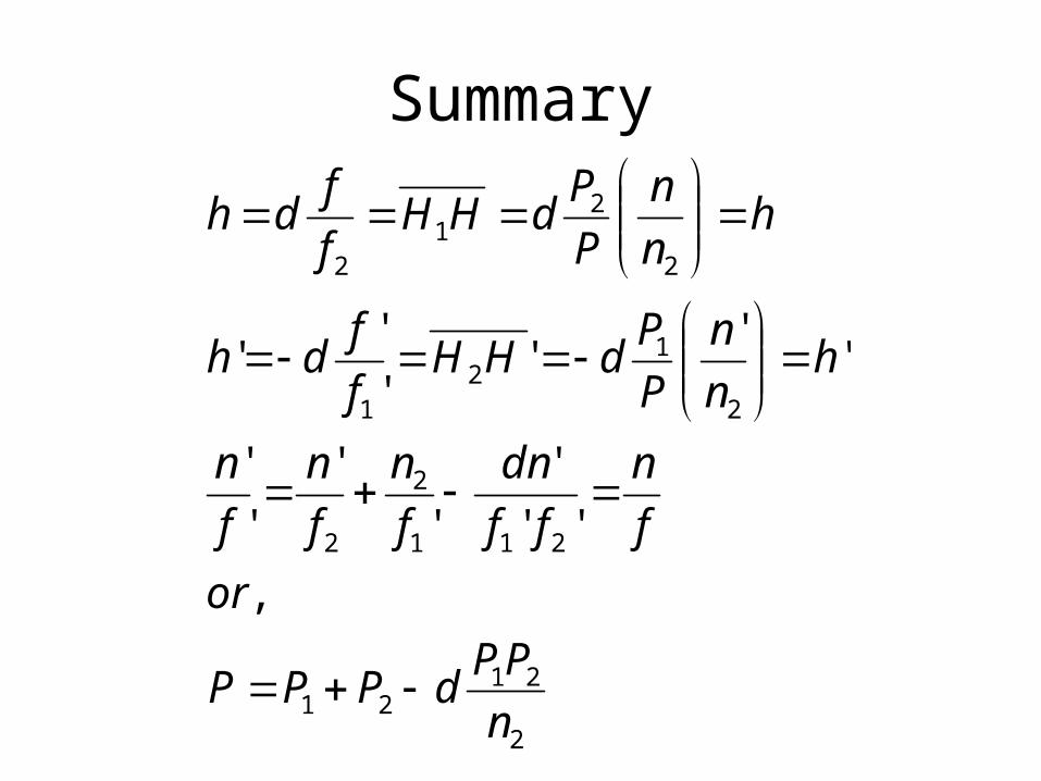
Summary
2
2121
211
2
2
2
12
1
2
21
2
,
''
'
'
'
'
'
''
''
''
n
PPdPPP
or
f
n
ff
dn
f
n
f
n
f
n
hn
n
P
PdHH
f
fdh
hn
n
P
PdHH
f
fdh