Chapter VII. Structural Analysis -...
20
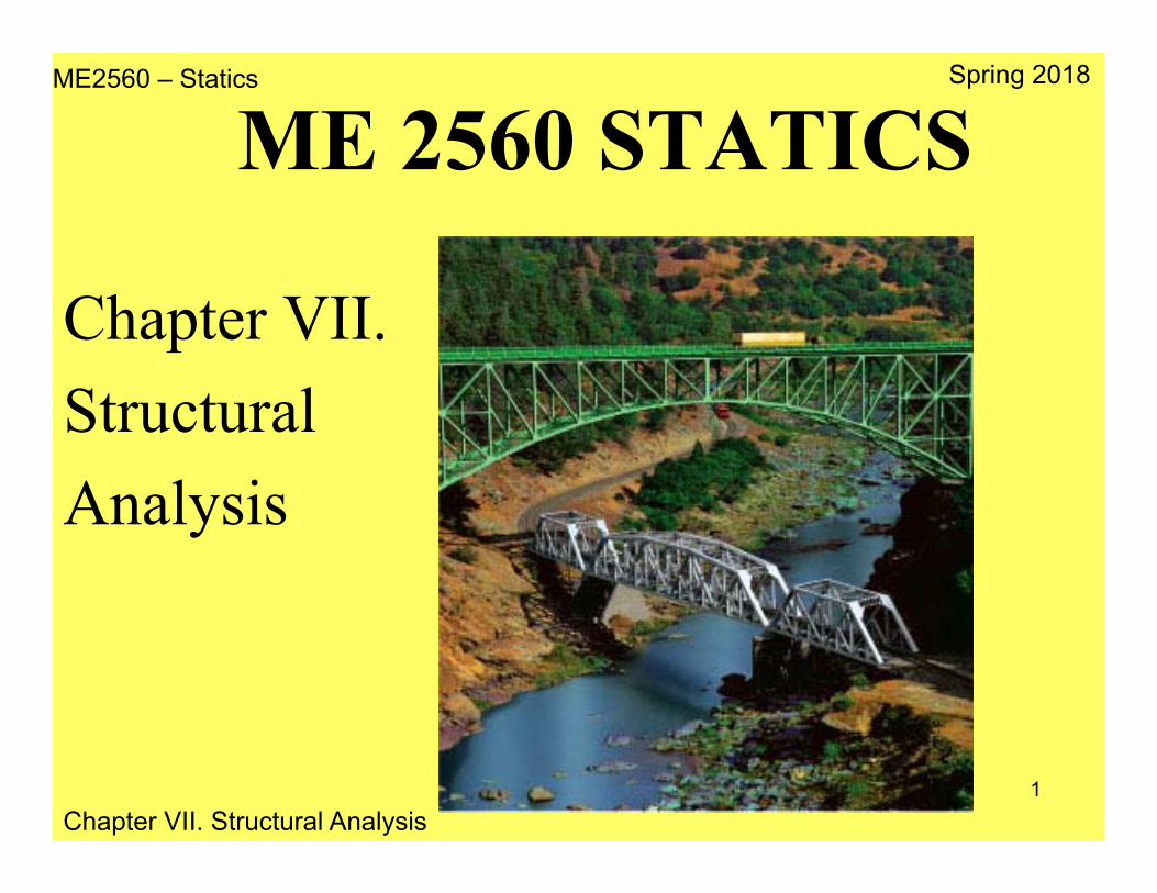
ME2560 – Statics Chapter VII. Structural Analysis Spring 2018 1 ME 2560 STATICS Chapter VII. Structural Analysis
Transcript of Chapter VII. Structural Analysis -...
ME2560 – Statics
Chapter VII. Structural Analysis
Spring 2018
1
ME 2560 STATICS
Chapter VII. StructuralAnalysis
ME2560 – Statics
Chapter VII. Structural Analysis
Spring 2018
2
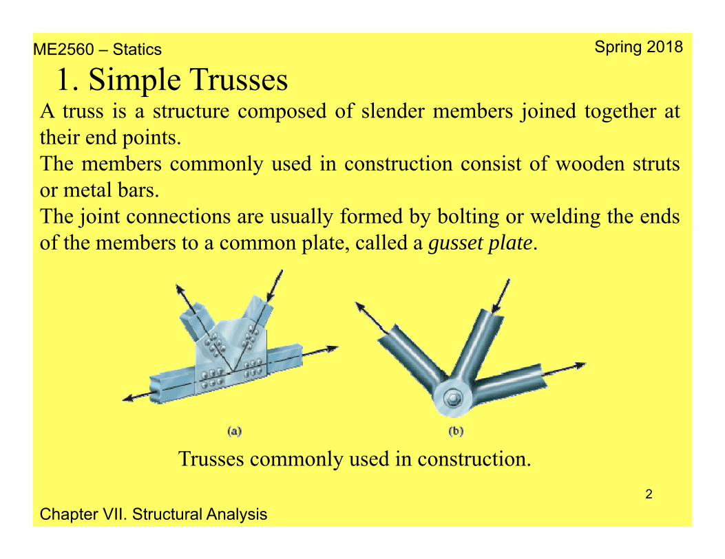
1. Simple TrussesA truss is a structure composed of slender members joined together attheir end points.The members commonly used in construction consist of wooden strutsor metal bars.The joint connections are usually formed by bolting or welding the endsof the members to a common plate, called a gusset plate.
Trusses commonly used in construction.
ME2560 – Statics
Chapter VII. Structural Analysis
Spring 2018
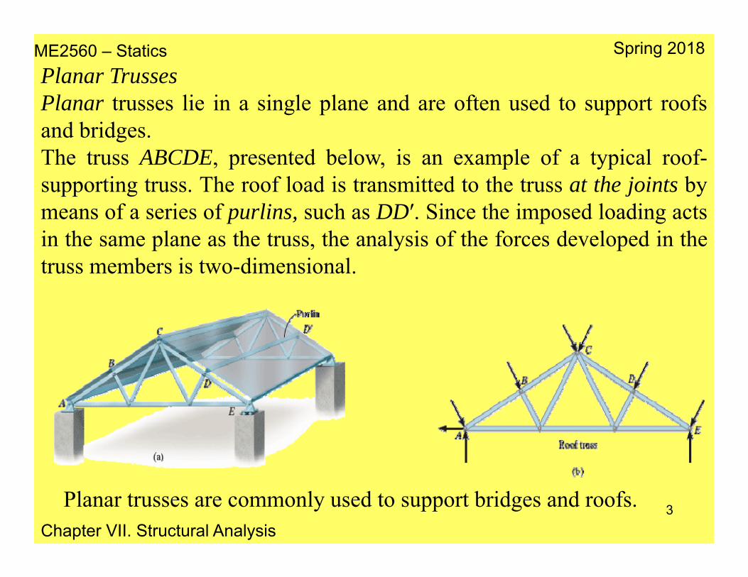
3Planar trusses are commonly used to support bridges and roofs.
Planar TrussesPlanar trusses lie in a single plane and are often used to support roofsand bridges.The truss ABCDE, presented below, is an example of a typical roof-supporting truss. The roof load is transmitted to the truss at the joints bymeans of a series of purlins, such as DD′. Since the imposed loading actsin the same plane as the truss, the analysis of the forces developed in thetruss members is two-dimensional.
ME2560 – Statics
Chapter VII. Structural Analysis
Spring 2018
4
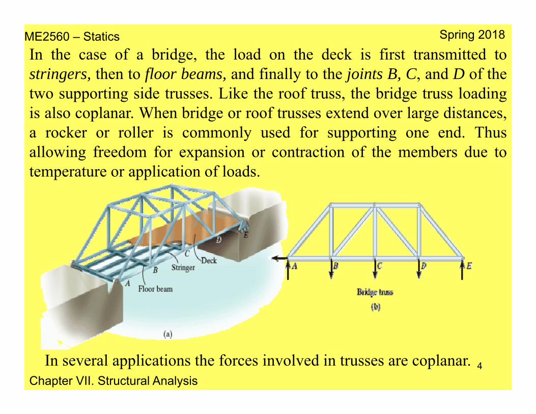
In the case of a bridge, the load on the deck is first transmitted tostringers, then to floor beams, and finally to the joints B, C, and D of thetwo supporting side trusses. Like the roof truss, the bridge truss loadingis also coplanar. When bridge or roof trusses extend over large distances,a rocker or roller is commonly used for supporting one end. Thusallowing freedom for expansion or contraction of the members due totemperature or application of loads.
In several applications the forces involved in trusses are coplanar.
ME2560 – Statics
Chapter VII. Structural Analysis
Spring 2018
5
Assumptions for Design
To design the members and the connections of a truss, the forcedeveloped in each member under working conditions must be calculated.Two important assumptions are made:
1. All loadings are applied at the joints. In most situations, such as forbridge and roof trusses, this assumption is true. Frequently in the forceanalysis the weight of the members is neglected since the forcessupported by the members are usually large in comparison with theirweight.If the member’s weight is to be included in the analysis, it is generallysatisfactory to apply it as a vertical force, with half of its magnitudeapplied at each end of the member.
ME2560 – Statics
Chapter VII. Structural Analysis
Spring 2018
6
2. The members are joined together by smooth pins. In cases wherebolted or welded joint connections are used, this assumption issatisfactory provided the center lines of the joining members areconcurrent.Thus, each truss member acts as a two-force member, and the forces atthe ends of the member must be directed along the axis of the member.
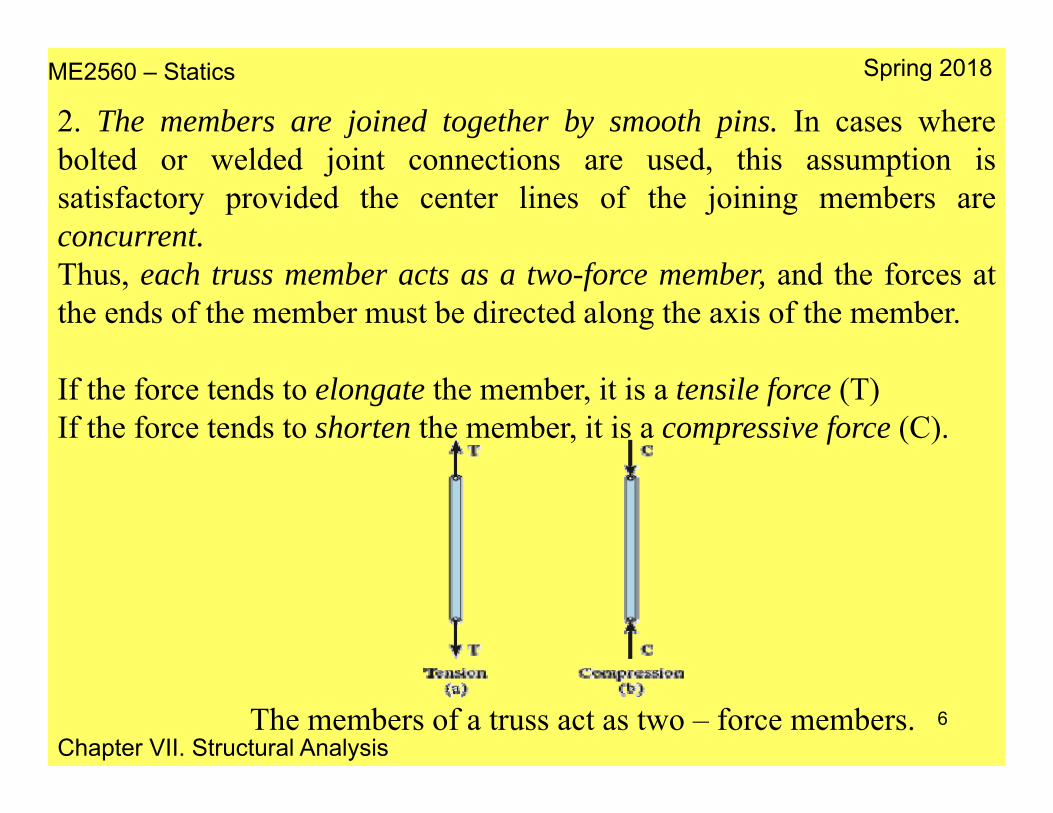
If the force tends to elongate the member, it is a tensile force (T)If the force tends to shorten the member, it is a compressive force (C).
The members of a truss act as two – force members.

ME2560 – Statics
Chapter VII. Structural Analysis
Spring 2018
7
The analysis or design of a truss requires the calculation of the force ineach of its members.
If a free–body diagram of the entire truss is sketched, the forces in themembers are internal forces and cannot be obtained from an equilibriumanalysis.
Considering the equilibrium of a joint of the truss then a member forcebecomes an external force on the joint’s free-body diagram, and theequations of equilibrium can be applied to obtain its magnitude.
This forms the basis for the method of joints.
2. The Method of Joints
ME2560 – Statics
Chapter VII. Structural Analysis
Spring 2018
8
Since the truss members are all straight two-force members lying in thesame plane, the force system acting at each joint is coplanar andconcurrent.Rotational or moment equilibrium is automatically satisfied at the joint(or pin),Thus equilibrium is ensured if ΣFx = 0 and ΣFy = 0.
The main steps to follow when using the method of joints are:•Draw a FBD of the structure to be analyzed•Determine the forces (reactions) produced by the supports on thestructure. This is achieved applying the equilibrium equations.•Draw the FBD of the joint to be analyzed. Recall that the line of actionof a force has the same direction as the corresponding member.• Determine the forces on each of the members on the joint by applyingthe equilibrium conditions on the joint.

ME2560 – Statics
Chapter VII. Structural Analysis
Spring 2018
9Process for analysis of a truss.
In the analysis of a joint we must start at a point that has at least one known force and at most two unknown forces.
ME2560 – Statics
Chapter VII. Structural Analysis
Spring 2018
10
Sense of an Unknown Member ForceThe correct sense of an unknown member force can be determined usingone of two possible methods:1. Always assume the unknown member forces acting on the joint’s free-body diagram to be in tension, i.e., “pulling” on the pin. If this is done, then numerical solution of the equilibrium equations will yield positive scalars for members in tension and negative scalars for members in compression. Once an unknown member force is found, use its correctmagnitude and sense (T or C) on subsequent joint free-body diagrams.
2. The correct sense of direction of an unknown member forcesometimes can be determined “by inspection”. In complicated cases,assume the sense of an unknown member force. After applying theequilibrium equations, a positive force indicates that the sense is correct,a negative force indicates that the sense shown on the free-body diagrammust be reversed.

ME2560 – Statics
Chapter VII. Structural Analysis
Spring 2018
11
Simplification on the analysis of a truss is achieved by first identifyingthe zero force members (support no loading).Zero-force members are used to increase the stability of the truss duringconstruction and to provide support if the applied loading is changed.
3. Zero Force Members
ME2560 – Statics
Chapter VII. Structural Analysis
Spring 2018
12
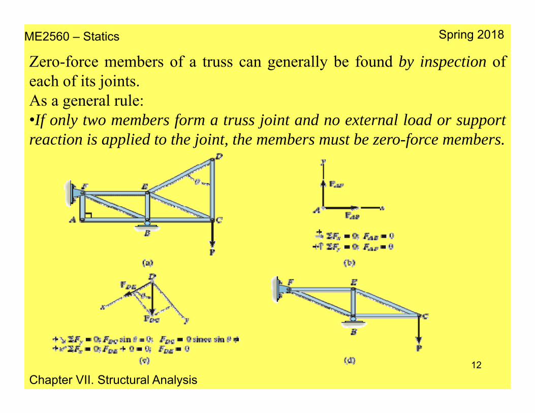
Zero-force members of a truss can generally be found by inspection ofeach of its joints.As a general rule:•If only two members form a truss joint and no external load or supportreaction is applied to the joint, the members must be zero-force members.

ME2560 – Statics
Chapter VII. Structural Analysis
Spring 2018
13
•If three members form a truss joint for which two of the members arecollinear, the third member is a zero-force member provided no externalforce or support reaction is applied to the joint.

ME2560 – Statics
Chapter VII. Structural Analysis
Spring 2018
14
If it is necessary to find the force in only a few members of a truss, themethod of sections is a more adequate process of analysis.This method is based on the principle that if a body is in equilibrium thenany part of the body is also in equilibrium.
4. The Method of Sections
Principle of the method of sections for calculating the force exerted to specific members of a truss.
ME2560 – Statics
Chapter VII. Structural Analysis
Spring 2018
15
Method of Sections Applied to a StructureBased on the concept that if a structure is in equilibrium, every elementof the structure must be in equilibrium, the method of sections can alsobe used to analyze a section the members of an entire truss.
If the section passes through the truss and the free-body diagram ofeither of its two parts is drawn, then the equations of equilibrium can beapplied to that part to determine the member forces at the “cut section.”
Since only three independent equilibrium equations (ΣFx = 0, ΣFy = 0,ΣMO = 0) can be applied to the isolated part of the truss.
Try to select a section that, in general, passes through not more thanthree members in which the forces are unknown.

ME2560 – Statics
Chapter VII. Structural Analysis
Spring 2018
16
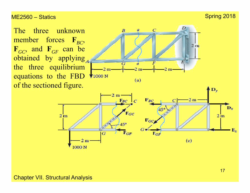
Consider the truss shown next. To determine FGC a cut through aa isappropriate.
Note that the line of action of each member force is specified from thegeometry of the truss, since the force in a member passes along its axis.The member forces acting on one part of the truss are equal but oppositeto those acting on the other part—Newton’s third law.
The members assumed to be in tension (BC and GC) are subjected to a“pull”, whereas the member in compression (GF) is subjected to a“push”.
ME2560 – Statics
Chapter VII. Structural Analysis
Spring 2018
17
The three unknownmember forces FBC,FGC, and FGF can beobtained by applyingthe three equilibriumequations to the FBDof the sectioned figure.

ME2560 – Statics
Chapter VII. Structural Analysis
Spring 2018
18
Frames and machines are two common types of structures which areoften composed of pin-connected multi-force members, i.e., membersthat are subjected to more than two forces.
•Frames are generally stationary and are used to support loads.
•Machines contain moving parts and are designed to transmit and alter the effect of forces.
If a frame or machine is properly constrained and contains only thenecessary supports or members to prevent collapse, the forces acting atthe joints and supports can be determined by applying the equations ofequilibrium to each member
5. Frames
ME2560 – Statics
Chapter VII. Structural Analysis
Spring 2018
19
Free–Body Diagrams
To determine the forces acting at the joints and supports of a frame ormachine, the structure must be disassembled and the free-body diagramsof its parts must be drawn. The following points must be observed:
•Isolate each part by drawing its outlined shape. Then show all the forcesand/or couple moments that act on the part.
•Identify all the two-force members in the structure and represent theirfree-body diagrams as having two equal but opposite collinear forcesacting at their points of application. Finding two force members willavoid solving extra equations.
ME2560 – Statics
Chapter VII. Structural Analysis
Spring 2018
20
•Forces common to any two contacting members act with equalmagnitudes but opposite sense on the respective members. If the twomembers are treated as a “system” of connected members, then theseforces are “internal” and are not shown on the free-body diagram of thesystem; however, if the free-body diagram of each member is drawn, theforces are “external” and must be shown on each of the free-bodydiagrams.
Equations of Equilibrium
If the frame or machine is properly supported and contains only the supports or members that are necessary to prevent its collapse, then the unknown forces at the supports and connections can be determined from the equations of equilibrium. If the structure lies in the x–y plane, then for each free-body diagram drawn the loading must satisfyΣFx = 0, ΣFy = 0, and ΣMO = 0.