CHAPTER V DIRECT TARGET - Servizi Nazionali
14
Chapter V – Direct Target 65 CHAPTER V DIRECT TARGET 1.1 The target concept Three important parameters are required to optimize a fission ISOL target: first of all a high number of fission reactions (to provide high RIB intensities), then a low power deposition in the target materials (to avoid melting temperatures) and finally a fast isotope release time (to improve extraction efficiency). The main problem for a direct target configuration concerns the power deposited by the incident beam in the production target, mainly due to the electromagnetic interactions. In order to solve this issue, only the protons with higher 238 U fission cross-section are exploited and the target was properly optimised from the thermal point of view. As a matter of fact, the 238 U fission cross-section and the stopping power have opposite dependency on the proton energy, as shown in figure 5.1 [2-4]. The low energy protons have high stopping power and release a high power in the target but are not so efficient for isotope production because their low fission cross-section. Fig. 5.1 Stopping power and fission cross-sect for protons on UC Fig. 5.2 Reference target configuration (the 7 UC x disks are shown in yellow and red) If the low energy protons (for example with energy lower than about 20 MeV) are driven towards a passive dump, the power deposited in the UCx target is lowered considerably and at the same time the number of fission reactions is maintained high. Moreover, the 238 U fission cross-section increases with the proton energy up to 40 MeV and than stay constant. For energies exciding 100 MeV, spallation enters in competition with the fission cross section and transuranium elements are produced complicating the radiation protection issue of the target management. With this in mind the target was designed for proton energy of 40 MeV and a possible upgrade up to 70 MeV will be considered in the future. In order to optimize the heat dissipation and the release time of the fission products [5], a multiple disks target was proposed [6]: the target is split into several thin disks increasing the total thermal exchange surface and the disks are separated accordingly to allow the cooling of the system by thermal radiation. The advantage of this configuration is the simplicity of the cooling system and the consequent relatively low cost. The reference diameter of the target disks is 6 cm, but recent thermal simulations indicate the possibility to decrease the diameter down to 4 cm. The detailed parameters used for the system (see figure 5.2) are the following [7]: 0 10 20 30 40 50 60 70 80 2 4 6 8 10 12 14 16 18 20 22 24 26 28 30 32 34 36 38 40 42 44 46 48 50 Proton energy (MeV) Stopping power (MeV cm 2 g -1 ) 0.0 0.5 1.0 1.5 2.0 2.5 3.0 3.5 4.0 Fission cross-section (barn) Stopping power Fission cross-section
Transcript of CHAPTER V DIRECT TARGET - Servizi Nazionali

Chapter V – Direct Target 65
CHAPTER V
DIRECT TARGET
1.1 The target concept
Three important parameters are required to optimize a fission ISOL target: first of all a high number of fission reactions (to provide high RIB intensities), then a low power deposition in the target materials (to avoid melting temperatures) and finally a fast isotope release time (to improve extraction efficiency). The main problem for a direct target configuration concerns the power deposited by the incident beam in the production target, mainly due to the electromagnetic interactions. In order to solve this issue, only the protons with higher 238U fission cross-section are exploited and the target was properly optimised from the thermal point of view.
As a matter of fact, the 238U fission cross-section and the stopping power have opposite dependency on the proton energy, as shown in figure 5.1 [2-4]. The low energy protons have high stopping power and release a high power in the target but are not so efficient for isotope production because their low fission cross-section.
Fig. 5.1 Stopping power and fission cross-sect for protons on UC
Fig. 5.2 Reference target configuration (the 7 UCx disks are shown in yellow and red)
If the low energy protons (for example with energy lower than about 20 MeV) are driven towards a passive dump, the power deposited in the UCx target is lowered considerably and at the same time the number of fission reactions is maintained high.
Moreover, the 238U fission cross-section increases with the proton energy up to 40 MeV and than stay constant. For energies exciding 100 MeV, spallation enters in competition with the fission cross section and transuranium elements are produced complicating the radiation protection issue of the target management. With this in mind the target was designed for proton energy of 40 MeV and a possible upgrade up to 70 MeV will be considered in the future.
In order to optimize the heat dissipation and the release time of the fission products [5], a multiple disks target was proposed [6]: the target is split into several thin disks increasing the total thermal exchange surface and the disks are separated accordingly to allow the cooling of the system by thermal radiation. The advantage of this configuration is the simplicity of the cooling system and the consequent relatively low cost.
The reference diameter of the target disks is 6 cm, but recent thermal simulations indicate the possibility to decrease the diameter down to 4 cm.
The detailed parameters used for the system (see figure 5.2) are the following [7]:
0
10
20
30
40
50
60
70
80
2 4 6 8 10 12 14 16 18 20 22 24 26 28 30 32 34 36 38 40 42 44 46 48 50
Proton energy (MeV)
Stop
ping
pow
er (M
eV c
m2 g
-1)
0.0
0.5
1.0
1.5
2.0
2.5
3.0
3.5
4.0
Fission cross-section (barn)
Stopping power
Fission cross-section

Chapter V – Direct Target 66
- the incident 40 MeV proton beam has a current of 0.2 mA. The beam profile spans uniformly over a circle distribution, which matches the disk radii;
- the window, necessary to separate the beam line from the target void regions, is made of one (or two) thin carbon foil of 400 µm total thickness;
- the UCx target (about ρ=2.5 g/cm3) is made of seven disks about 1.3 mm thick each; - the beam dump is made of three carbon disks about 0.9 mm thick each; - the box containing the disks is made of graphite.
1.2 The in-target yields
The following results are obtained through several MonteCarlo calculations (MCNPX code [8, 9] with the ORNL fission model) performed for the target configuration described in the previous section. It turns out that a power of 0.19 kW is deposited in the window, 4.1 kW in the seven UCx disks, 1.7 kW into the three dump disks and 2.2 kW are lost outside the disks (due to proton scattering). Thus, the average power deposition for the UCx target disks is about 4.1 kW / 7 disks = 0.58 kW/disk.
The power deposition with its radial profile in the disks is reported in fig. 5.3.
Fig. 5.3 Radial distribution of the power deposition in the disks (without considering build up and decays)
Fig. 5.4 Fission mass spectra yields
As expected, the radial profile is uniform in the window (following the entering uniform beam
profile) and it becomes less and less flattened in the last disks, because of the proton scattering.
Fig. 5.5: Representation of the in-target isotope production.
0
50
100
150
200
250
300
350
400
450
0 0.25 0.5 0.75 1 1.25 1.5 1.75 2 2.25 2.5 2.75 3
r (cm)
Wat
t cm
-3
Windowdisk 1disk 3disk 5disk 7dump 2dump 3
0.0E+00
5.0E+10
1.0E+11
1.5E+11
2.0E+11
2.5E+11
3.0E+11
3.5E+11
4.0E+11
60 70 80 90 100 110 120 130 140 150 160 170
Mass number (A)
Ato
m p
rodu
ctio
n (s
-1)

Chapter V – Direct Target 67
The total calculated fission rate in all the seven disks is about 1·1013 fissions s-1. The peak-to-valley ratio in the mass number distribution of the fission products, that is very pronounced in thermal neutron induced fissions at about A=115-120, is here only about a factor of 2 (see figure 5.4).
The isotope in-target production reaches values up to ~1011 atoms/s. The 132Sn isotope, being a double-magic nucleus, is one of the radioactive nuclei of interest. Its production is here estimated to be ~1·109 s-1. A more general view of the in-target yields is given in figure 5.5.
1.3 The target thermal analysis
The power distribution shown in the previous section has been used for a target thermal analysis. The power is deposited in the target components (i.e. target disks, dump disks and box) mainly due to the beam-materials interaction. Due to the low pressure environment, this heat has to be removed by thermal radiation to the heat sink constituted by the chamber (see figure 5.6). This process can be divided into two steps: the disks (of the target and of the dump) are radiating toward the box, which, in turn, will transfer the heat to the chamber wall, also by radiation. It has to be pointed out that the box has to be held at about 2000°C for optimizing the fission product extraction; the chamber wall will be at about room temperature.
The reference target steady state thermal analysis was performed by means of some ad hoc models and by using the ANSYS code; the results were mainly presented in [6, 7].
With respect to the disks, the analysis was mainly devoted to evaluate the maximum temperature, in order to warrant that no melting will occur. This analysis was performed by taking into account the actual power distribution both in the disk radial and axial (beam) directions. The results obtained for the UCx disks show, even in the most heated disk, a safe margin with respect to melting. In the dump disks the temperatures are sensibly lower.
Fig. 5.6: Longitudinal and radial temperature distributions from ANSYS calculations.
With respect to the box, the heat deposited in the target is not enough to keep it at 2000 °C. This situation can be faced either by introducing thermal shields between the box and the chamber walls, or by adopting an independent power supply system for the box. The present proposal is to exploit both of these solutions: to introduce the power supply in order to face better the transient situation, and to insert the thermal shields in order to drive to some optimal amount the power to be supplied.
In the first calculations the chamber wall was assumed to be at room temperature; this situation can be easily achieved by adopting a simple water cooling system. Further investigations show the possibility to cool the chamber even by natural air convection: in this way the chamber temperature is increased but the effect on the target is negligible, particularly when thermal shields are present.
1.4 The target thermo-mechanical analysis
The disk thermo-mechanical state of stress was analysed referring to the previously calculated temperature distribution. A particular disk (the sixth) was chosen as representative of an adequately
Chapter V – Direct Target 68
conservative operating condition. The calculation, however, was drastically simplified by the assumptions of elastic material and steady-state regime. Moreover, the UCx physical properties are not sufficiently known and further measurements are to be carried out.
Differential thermal expansions are generated in each UCx disk by the non-uniform temperature distribution originated from the distribution of the proton beam. The state of stress arising from such differential expansions was examined.
Different approaches were attempted and lead to similar results: • an order-of-magnitude analysis [10]; • a numerical treatment of the equations of linear elasticity both in one- and two-dimensions [11,12]; • a commercial avalable code (ANSYS).
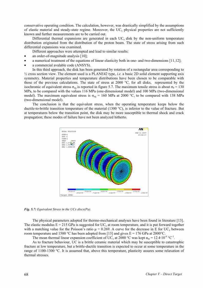
In this third approach, the disk has been generated by rotation of a rectangular area corresponding to ½ cross section view. The element used is a PLANE42 type, i.e. a basic 2D solid element supporting axis symmetry. Material properties and temperature distributions have been chosen to be comparable with those of the previous calculations. The state of stress at 2000 °C, for all disks, represented by the isochromic of equivalent stress σeq is reported in figure 5.7. The maximum tensile stress is about σθ = 130 MPa, to be compared with the values 116 MPa (one-dimensional model) and 100 MPa (two-dimensional model). The maximum equivalent stress is σeq = 160 MPa at 2000 °C, to be compared with 138 MPa (two-dimensional model).
The conclusion is that the equivalent stress, when the operating temperature keeps below the ductile-to-brittle transition temperature of the material (1300 °C), is inferior to the value of fracture. But at temperatures below the transition point, the disk may be more susceptible to thermal shock and crack propagation; these modes of failure have not been analyzed hitherto.
Fig. 5.7: Equivalent Stress in the UCx discs(Pa).
The physical parameters adopted for thermo-mechanical analyses have been found in literature [13].
The elastic modulus E = 215 GPa is suggested for UCx at room temperature, and it is put forward together with a matching value for the Poisson’s ratio µ = 0.269. A curve for the decrease in E for UCx between room temperature and 1500 °C has been adopted from [13] and gives E = 176 GPa at 2000°C.
The mean thermal linear expansion coefficient of UCx at 2000 °C was kept αm = 12.4·10-6 °C-1. As to fracture behaviour, UC is a brittle ceramic material which may be susceptible to catastrophic
fracture at low temperature, but a brittle-ductile transition is expected to occur at some temperature in the range of 1100-1300 °C. It is assumed that, above this temperature, plasticity assures some relaxation of thermal stresses.
1
MNMX
XY
Z
Target SPES
.797E+07.291E+08
.502E+08.714E+08
.925E+08.114E+09
.135E+09.156E+09
.177E+09.198E+09
FEB 11 200723:44:17
NODAL SOLUTION
STEP=1SUB =1TIME=1SEQV (AVG)DMX =.571E-03SMN =.797E+07SMX =.198E+09
Chapter V – Direct Target 69
Fracture stress is given up to ~1300 °C only, where it is σ ≈ 200 MPa. The assumption of linearity seems rather adequate up to ~1300 °C, more questionable beyond.
Therefore the study has been iterated at 1300 °C and 2000 °C. The first result (1300 °C) represents the brittle behaviour, while the second result (2000 °C) is a sort of ‘best indicator’ of what happens in nominal operation.
1.5 Release time calculations
The final intensity of a radioactive ion beam depends on the efficiency of different processes: the target production yield, the target efficiency, the ionization efficiency, the transportation efficiency along the accelerator. In order to optimize the target efficiency it is very important to minimize the time needed by the radioactive species to join the ion source.
Several simulations have been performed using the GEANT4 toolkit [14], as well as the RIBO (Radioactive Ion Beam Optimization) code [15], in order to estimate the release time for some neutron-rich nuclei. The target temperature was 2000°C in all the simulations.
The main release mechanisms in an ISOL target is discussed in Chapter 3. The diffusion from the grains of the target materials, the effusion in the inter-grain space and the free-effusion are taken into account.
Additionally, each collision may involve an average adsorption-desorption time, ts (sticking time). Release time calculations were performed considering the release of the neutron rich atoms 132Sn
and 90Kr. In the calculations we assumed our UCx disks being made with standard ISOLDE UCx so the
ISOLDE parameters have been used: . average flight path in the powder FP = 15 µm, . sticking time for Sn isotopes ts = 10-6 s, . diffusion time constant for Sn isotopes τD = 1 s . diffusion time constant for Kr isotopes τD = 10 s [16].
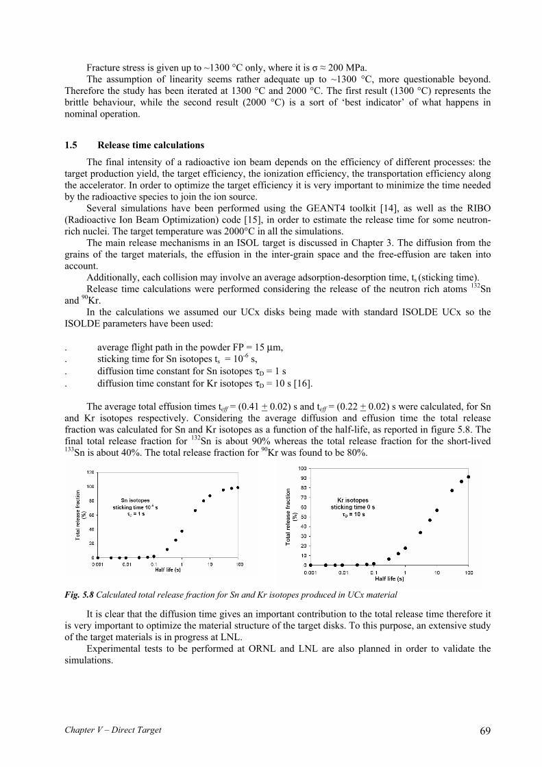
The average total effusion times teff = (0.41 + 0.02) s and teff = (0.22 + 0.02) s were calculated, for Sn and Kr isotopes respectively. Considering the average diffusion and effusion time the total release fraction was calculated for Sn and Kr isotopes as a function of the half-life, as reported in figure 5.8. The final total release fraction for 132Sn is about 90% whereas the total release fraction for the short-lived 133Sn is about 40%. The total release fraction for 90Kr was found to be 80%.
Fig. 5.8 Calculated total release fraction for Sn and Kr isotopes produced in UCx material
It is clear that the diffusion time gives an important contribution to the total release time therefore it is very important to optimize the material structure of the target disks. To this purpose, an extensive study of the target materials is in progress at LNL.
Experimental tests to be performed at ORNL and LNL are also planned in order to validate the simulations.

Chapter V – Direct Target 70
1.6 The target pellets development
Radioactive Ion Beam (RIB) production is deeply affected by the characteristics of the target impinged by the proton beam. The composition and the degree of purity of the constituent materials, the microstructure and morphology (i.e. crystalline phase, grain size, porosity) of the target are of particular importance to this purpose. The kind of isotopes produced, in turn, depends both on the energy of the incident beam and on the fissile material, whereas the efficiency release is mainly related to the isotopes diffusion inside the target and to their gas-phase effusion (molecular flow plus multiple ad-desorption) [17].
Both the diffusion and effusion of the radioactive species in/from the target strongly increase with the increase of the temperature. For this reason the target working temperature must be kept as high as possible, in order to grant atoms release faster than their decay. On the other hand, the working temperature of the target is limited by the vapour pressure of the target constituents, by the stability of the target at high temperatures and by possible reactions which may occur between the target and the target holder at high temperature.
For these reasons, refractory compounds like carbides and oxides have to be used as target materials in order to sustain these conditions. For the production of some isotope beams planned in the SPES project, uranium and thorium fissile isotopes were already suggested and uranium and thorium oxides and carbides were accordingly employed. Mixtures of uranium oxide and graphite at high temperature showed particularly favourable release characteristics for many isotopes [18-20]. In particular, UCx can be produced by reaction of a precursor (metal oxide) with a carbon based matrix (graphite powder or low density carbon foam generators) according to equation 2. UO2 + 4C + nC UC2 + 2CO(g) + nC (2)
Fig. 5.9 Left, the high temperature and high vacuum furnace assembled at LNL; right, picture of the 13-mm and 40-mm diameter pellets of LaC2 dispersed in graphite before thermal treatment. In the insert the hydraulic press is shown.
The formation of uranium carbide occurs under high vacuum at temperatures ranging from 1100 to
1400 °C. The gas released during carbo-thermal reduction (CO in eq. 2) is responsible for pores formation. Open porosity (interconnected structure) was demonstrated to improve isotope release [21]. Moreover, in order to obtain materials withstanding the extreme working conditions, sintering of the composite powder is a successive, necessary, step achieved at temperatures even higher than 1700 °C. The main goal here is to design a standard procedure aimed to the production of uranium carbide-based
b) a)

Chapter V – Direct Target 71
pellets with the best online performances. This can be achieved, by a careful characterization of prepared pellets by an optimized thermal treatment of several oxide and graphite mixtures, in different ratio and with dimensions ranging from nano- to micro-meters. In addition, similar procedures and characterizations will be extended to new promising porous, low-density ceramic materials (UCx or LaCx foams).
Handling radioactive material (even if of low activity like depleted uranium) requires special precautions, authorizations, and dedicated radiological controlled area to avoid workers and instruments contamination. All this often contrasts with the need to obtain results in a short time and indicated the usage of lanthanum dicarbide (LaC2) as a valuable substitute of uranium compounds for preliminary bench tests on pellet production and characterization. Beside radiological aspect, preparation of pellets of lanthanum carbide and/or uranium carbide dispersed in graphite, present similar challenges in both synthesis and characterization. According to the schedule and priorities planned in the SPES direct target project, two production lines for 13-mm and 40-mm diameter pellets have been developed. In figure 5.9 a) the evaporator assembly and b) a picture of the two kinds of pellets are reported. The insert shows the hydraulic press used for the pellet production.
Fig. 5.10 (A) Scanning Electronic Microscope (SEM); (B) X-ray diffractometer (XRD); (C) TG/DSC thermal instrument.
At present, several disks of LaC2 dispersed into graphite were produced with diameter 13 mm and 40 mm and thickness 1 mm. The disks are produced by mixing an appropriate amount of lanthanum oxide, graphite and polyphenol resin as binder, the powders mixtures are cold pressed and the green pellets heat treated under vacuum. The heat treatment schedule has been designed as consequence of Differential Scanning Calorimetry (DSC) analysis performed on the starting mixture, X-Ray Diffractometer (XRD) and SEM-EDS investigations of samples carburized and sintered at different temperatures (see figure 5.10). At present, pellet carburization and sintering has been achieved.
Fig. 5.11 Left, SEM-EDAX analysis on LaCx samples after heat treatment and right, the process evolution by XRD measurements
In figure 5.11 the SEM micrograph obtained from the surface of a La-C sample after treatment at 1800°C, under Ar flow is reported. The images on the right in the figure show that EDS elemental
20 30 40 50
La/C/18A ∗ Graphite◊ La(OH)3 JCPD 83-2034° La2O3 JCPD E 05-0602 ♦ LaC2 JCPD 74-0903
♦♦♦
∗°
°
° °°
◊
◊◊
◊
◊
◊
°
°°
°
Inte
nsity
(arb
. uni
ts)
2θ
raw
La/C/12
La/C/18
°∗◊
♦

Chapter V – Direct Target 72
analysis performed with a narrow spot on different areas of the specimen is able to discriminate the different chemical compositions.
20 40 60 80 100
0,0
0,2
0,4
0,6
0,8
1,0
§ * **
*
**** *
**
*
*
Inte
nsity
2θ
*
* α−UC2 pdf # 84-1344
§
§ Graphite pdf #
Fig.5.12 SEM analysis of UCx target and XRD after carburization and sintering
Moreover, LaCx samples with tailored properties are prepared starting from lanthanum oxalate, lanthanum oxide and graphite mixtures. By mixing in different molar ratios the constituents materials LaCx samples (13 mm diameter) are produced and properties such as the amount of open and closed porosity, density and emissivity are properly controlled.
The control of emissivity represents a key point of target development since at high temperatures it represents the main responsible, together with thermal conductivity, for heat dissipation.
The production of UCx samples is also started and first disks prototypes have been produced and characterized as shown in figure 5.12. Following the route showed by LaCx disks, UCx samples with controlled amount of porosity and tailored emissivity are under development. As reported in figure 5.12, XRD analyses show the formation of tetragonal UC2 and graphite. A minor amount of a secondary U-C phase was also formed up on carburization and sintering. Samples possessing a bulk density of about 3 g/cm3 and grain size less than 1 µm have been produced.
Three main routes are nowadays available for the production of porous materials: a) the replica technique: a polymeric sponge is impregnated by a slurry of appropriate composition, the system is then dried and the polymeric sponge burnt-off; b) the direct foaming technique: a foaming agent is introduced into a suspension of appropriate composition; c) the sacrificial templates technique: a sacrificial component with selectable shape and size is introduced in the system and then burnt-off, leaving empty spaces.
In the future production of LaCx and UCx pellets the different techniques will be employed to vary the sample porosity (from <10 %, dense target, to 70-80%, typical value of foams) and the pore dimensions and shape (spheroidal, acicular). In particular, the porosity will be realized either by means of sacrificial fillers (PMMA based micro-spheres that decompose completely during the thermal treatment) or by direct foaming methods (mixing the raw materials with a low-temperature evaporation solvent) or with the replica technique (polymeric foams covered by ceramic powder and treated at high

Chapter V – Direct Target 73
temperatures). In this way, it will be possible to acquire the necessary know-how to control not only the shape and dimensions of the pores but also their morphological characteristics: passage from a closed to an open structure would significantly improve the target permeability. All the correlations between the observed effusion properties of the on line targets and their structural properties will be exploited in order to improve technology of the pellet production.
1.7 The target chamber design
1.7.1 The target-ion source unit
We have adapted the engineering principles embodied in the target source modules used at CERN-ISOLDE for remote and safe handling [22]. The attractive feature of this approach is that loose contamination is enclosed in a relatively compact system.
Fig 5.13 The target system (UCx disks dump, graphite container) inserted into tantalum heater (left), and the whole target-ion source chamber unit (right).
The target unit is made of a graphite box containing the UCx, windows and dumps (both in graphite) disks, and is contained in a tantalum cylinder which is resistively heated by passing a high current through it in addition to the heat supplied by the irradiating beam. A Tantalum tube (transfer tube) connects the target unit to the ion source according to the ISOLDE concept (possibility to plug in several kinds of ion sources).
The SPES target and ion source are mounted on vacuum feed-through situated in a water-cooled base plate and enclosed by an aluminium bell jar. Two valves isolate the system. A drawing of the target unit and the target-ion source chamber are shown in figure 5.13 and 5.14.

Chapter V – Direct Target 74
Fig. 5.14 Mechanical drawing of SPES target-ion source chamber.
1.7.2 The target chamber handling
The SPES target ion sources chamber is designed in such a way that it can be removed for servicing or storage by disconnection from, or reconnection to, the beam transport system. The unit is coupled to the RIB exit line and to the proton driver beam by means of two quick connectors and two pumping ports which can be sealed off with valves. Since the target can be used several times, it will be stored into a container with thick (2 cm) lead walls while not used. The handling system must be designed in order to transport such heavy container (150Kg) into the area where the target will be used, to open the container and to connect the source chamber to injector. After the experiment, the source chamber must be at first removed from the injector, then stored in the container and finally sent out of the “hot” area for further handling and long term storage.
Figure 5.15 shows the proposed handling system, composed of a dedicated chamber positioning guide, which provides the handling in both irradiation areas. The container stops in front of the irradiation area, the door is opened and the target moved toward the injector by using a self-aligning, high precision insertion system. After the experiment, the target is re-stored in the container, which is closed before being pushed out of the radiation area.

Chapter V – Direct Target 75
Fig. 5.15 The lead box for the target container connected to the handling system (left) and the two SPES irradiation area coupled to the primary and RIB beam lines (right).
1.8 The target prototype
In order to develop the final SPES multi-foil Direct Target a research program has been activated to test the target configuration with proton beams of suitable energy. The elective facility to perform these tests is HRIBF (Holified Radioactive Ion Beam Facility) at ORNL [23]. HRIBF is indeed based on a primary beam of protons at 40 MeV with current up to 20 µA. The first step in this program is to develop a target prototype with dimensions scaled to 1:5 with SiC disks (see figure 5.16 and 5.17).
Fig. 5.16 SiC SPES target prototype tested at HRIBF.
This prototype fits inside the HRIBF target holder, allows testing the main ion release characteristics
and gives the first experimental thermal behaviour of the multi slide configuration in a condition of nominal power density up to about 600 W/g. The use of SiC target is devoted to the production of exotic aluminium beams, 25Al and 26Al , which are isotopes of astrophysical interest both at HRIBF and EXCYT.
The preliminary data of the first test performed in December 2006 with a SiC disks confirm the prediction [24] of the thermal simulations.

Chapter V – Direct Target 76
Fig. 5.17 SiC SPES target inside the target heater (left) and the target area at HRIBF (right).
A comparison between different target configurations and materials will be done. The first one is the standard HRIBF target, made of pressed powder or pills; the second one the multi-slide configuration proposed here.
Dumper Temperature measurement
600
900
1200
1500
1800
2100
2400
300 400 500 600 700 800
Heater Current [A]
T [°C]
Experimental - Without shieldsExperimental - With shieldsFEM - Without shieldsFEM - With shieldsPoli. (Experimental - With shields)Poli. (Experimental - Without shields)
Fig. 5.18 Temperature measurements of the last dumper side of SiC SPES target at HRIBF.
In the first experiment two heater configurations (with and without additional shield) were tested. In figure 5.18 the experimental results, reading by a pyrometer the back side of the last dumper in the target, are reported and compared with FEM calculations.
The aluminium isotopes production was measured as a function of proton current and heater temperature. The results are reported in figure 5.19

Chapter V – Direct Target 77
Aluminum Isotopic Chain
10
100
1000
10000
100000
24.5 25 25.5 26 26.5 27 27.5 28 28.5 29 29.5
Mass (amu)
Coun
ts/s
2 microA, 1800°C
5 microA, 1800°C10 microA, 1800°C
12 microA, 1800°C
2 microA, 1600°C
Fig. 5.19 Aluminium isotopes production of SiC SPES target at HRIBF.
The target performance was considered very satisfying and this target is actually used at HRIBF. ____________________ [1] A. Andrighetto, Proceeding of Exon 2004 Internatioal Conference (2004). [2] P.C. Stevenson et al., Phys. Rev. 111 (3), 886 (1958). [3] S. Baba et al., Nucl. Phys. A 175, 177 (1971). [4] B.L. Tracy et al., Phys. Rev. C 5 (1), 222 (1972). [4a] M.Re et al. RNB7 conference proceedings, Cortina, Italy, July 2006, in publication [6] A. Andrighetto, S. Cevolani, C. Petrovich, Eur. Phys. J. A 25, 41 (2005). [7] A. Andrighetto, C. Antonucci, S. Cevolani, C. Petrovich, M. Santana Leitner, Eur. Phys. J. A 30, 591 (2006). [8] Denise B. Pelowitz (Editor), MCNPXTM User’s manual, Version 2.5.0, LA-CP-05-0369 (2005). [9] H.W. Bertini, Phys. Rev. 131 4, 1801 (1963). [10] A. Andrighetto, C.M. Antonucci, S. Cevolani, C. Petrovich, ENEA contribution to the design of the thin
target for the SPES project, FIS-P815-020 (ENEA, 2006), http://www.bologna.enea.it/pubblicazioni.html . [11] Timoshenko, Goodier, Theory of Elasticity (McGraw Hill, 1970). [12] Z. Zudans, T.C. Yen, W.H. Steigelmann, Thermal Stress Techniques in the Nuclear Industry (Elsevier, 1965). [13] Hj. Matzke, Science of advanced LMFBR fuels (North Holland, 1980). [14] S. Agostinelli et al., Nucl. Instr. Meth. A 506, 250 (2003). [15] M. Santana Leitner, A Monte Carlo Code to Optimize the Production of Radioactive Ion Beams by the ISOL
Technique, PhD. Thesis, UPC-ETSEIB / CERN (2005). [16] J. Crank, The Mathematics of Diffusion, Clarendon Press (1956). [17] R. Kirchner, Nucl. Instr. Meth. B 126, 135–140 (1997). [18] Y. Zhang et al., Nucl. Instr. and Meth. in Phys. Res. A, 521, 72–107 (2004). [19] G. D. Alton, Applied Radiation and Isotopes, 64, 1574–1603 (2006) [20] C. Lau et al., Nucl. Instr. Meth. in Phys. Res. B, 204, 246-250 (2003) [21] D.W. Stracener et al., Nucl. Instr. Meth. in Phys. Res. A, 521, 126–135 (2004) [22] S. Sundell and H. Ravn, NIM B 70 160 (1992). [23] G.D. Alton, NIM A 382 207 (1996). [24] S.Cevolani FIS-P815-022

Chapter V – Direct Target 78
![Carta Servizi Standard Vettore 2020 - Blue …Carta Servizi Standard Vettore 2020 - Blue Panorama Airlines ... ò } ]](https://static.fdocuments.us/doc/165x107/5f4a23096d5e3861ec3d3bd8/carta-servizi-standard-vettore-2020-blue-carta-servizi-standard-vettore-2020-.jpg)