Chapter Thirty-six INTERSECTIONS - Illinois Department · PDF file ·...
187
BUREAU OF DESIGN AND ENVIRONMENT MANUAL Chapter Thirty-six INTERSECTIONS
Transcript of Chapter Thirty-six INTERSECTIONS - Illinois Department · PDF file ·...

BUREAU OF DESIGN AND ENVIRONMENT MANUAL
Chapter Thirty-six
INTERSECTIONS

Illinois INTERSECTIONS September 2010
HARD COPIES UNCONTROLLED

Illinois INTERSECTIONS March 2017
36-i HARD COPIES UNCONTROLLED
Chapter Thirty-six INTERSECTIONS
Table of Contents
Section Page 36-1 GENERAL DESIGN CONTROLS .......................................................................... 36-1.1
36-1.01 General Design Considerations ............................................................ 36-1.1 36-1.02 Intersection Components ..................................................................... 36-1.4 36-1.03 Intersection Types ................................................................................ 36-1.5
36-1.03(a) General ......................................................................... 36-1.5 36-1.03(b) Alternative Intersection Designs .................................... 36-1.5
36-1.04 Intersection Spacing ............................................................................. 36-1.5 36-1.05 Intersection Alignment .......................................................................... 36-1.6
36-1.05(a) Angled Intersections ...................................................... 36-1.6 36-1.05(b) Intersections on Curves................................................. 36-1.9 36-1.05(c) Offset Intersections ....................................................... 36-1.12
36-1.06 Profiles ................................................................................................. 36-1.15
36-1.06(a) Approach Gradients ...................................................... 36-1.15 36-1.06(b) Cross-Section Transitions ............................................. 36-1.16 36-1.06(c) Profiles at Intersections ................................................. 36-1.17 36-1.06(d) Drainage ....................................................................... 36-1.19
36-1.07 Intersection Capacity Analysis .............................................................. 36-1.19 36-1.08 Design Vehicles ................................................................................... 36-1.19
36-1.08(a) Types ............................................................................ 36-1.19 36-1.08(b) Selection ....................................................................... 36-1.20
36-1.09 Pedestrians and Bicyclists .................................................................... 36-1.21 36-1.10 Pavement Markings/Reflectorized Markers .......................................... 36-1.22 36-1.11 Intersection Lighting ............................................................................. 36-1.22 36-1.12 Bus Turnouts ........................................................................................ 36-1.22
36-2 TURNING RADII ................................................................................................... 36-2.1
36-2.01 Design for Right-Turning Vehicles ........................................................ 36-2.1
36-2.01(a) Design Vehicle .............................................................. 36-2.1 36-2.01(b) Inside Clearance ........................................................... 36-2.1 36-2.01(c) Encroachment ............................................................... 36-2.1 36-2.01(d) Parking Lanes/Shoulders .............................................. 36-2.2 36-2.01(e) Pedestrian Considerations ............................................ 36-2.2

Illinois INTERSECTIONS March 2017
36-ii HARD COPIES UNCONTROLLED
Table of Contents (Continued)
Section Page 36-2.01(f) Types of Right-Turn Designs ......................................... 36-2.4 36-2.01(g) Stop Bar Locations ........................................................ 36-2.4 36-2.01(h) Turning Template(s) ...................................................... 36-2.4 36-2.01(i) Summary ...................................................................... 36-2.4 36-2.01(j) Local Street Reconstruction .......................................... 36-2.6
36-2.02 Corner Islands ...................................................................................... 36-2.6 36-2.03 Turning Roadways ............................................................................... 36-2.10
36-2.03(a) Guidelines ..................................................................... 36-2.10 36-2.03(b) Design Speed ............................................................... 36-2.12 36-2.03(c) Width............................................................................. 36-2.12 36-2.03(d) Horizontal Alignment ..................................................... 36-2.15 36-2.03(e) Deceleration/Acceleration Lanes ................................... 36-2.17
36-2.04 Left-Turn Control Radii ......................................................................... 36-2.21
36-3 AUXILIARY TURN LANES .................................................................................... 36-3.1
36-3.01 Turn Lane Guidelines ........................................................................... 36-3.1
36-3.01(a) Right-Turn Lanes .......................................................... 36-3.1 36-3.01(b) Left-Turn Lanes ............................................................. 36-3.4
36-3.02 Design of Turn Lanes ........................................................................... 36-3.15
36-3.02(a) Turn Lane Widths .......................................................... 36-3.15 36-3.02(b) Turn Lane Lengths ........................................................ 36-3.15
36-3.03 Left-Turn Lane Designs ........................................................................ 36-3.19
36-3.03(a) General Criteria ............................................................. 36-3.19 36-3.03(b) Parallel Left-Turn Lanes Without Offset ......................... 36-3.23 36-3.03(c) Offset Left-Turn Lanes .................................................. 36-3.26
36-3.04 Right-Turn Lanes ................................................................................. 36-3.33 36-3.05 Dual Turn Lanes................................................................................... 36-3.33
36-3.05(a) Guidelines ..................................................................... 36-3.33 36-3.05(b) Design........................................................................... 36-3.33
36-4 CHANNELIZING ISLANDS .................................................................................... 36-4.1
36-4.01 Island Types ......................................................................................... 36-4.1 36-4.02 Selection of Island Type ....................................................................... 36-4.1

Illinois INTERSECTIONS March 2017
36-iii HARD COPIES UNCONTROLLED
Table of Contents (Continued)
Section Page 36-4.02(a) Flush or Traversable Islands ......................................... 36-4.2 36-4.02(b) Raised-Curb Islands ...................................................... 36-4.2 36-4.02(c) Pavement Edge Islands ................................................ 36-4.3
36-4.03 Design of Islands.................................................................................. 36-4.3
36-4.03(a) Channelizing Islands ..................................................... 36-4.3 36-4.03(b) Corner Islands ............................................................... 36-4.6 36-4.03(c) Curb Ramps .................................................................. 36-4.6
36-4.04 Median Openings ................................................................................. 36-4.6
36-4.04(a) Location/Spacing .......................................................... 36-4.6 36-4.04(b) Design........................................................................... 36-4.7
36-5 EXTENSION OF THROUGH LANES BEYOND AN INTERSECTION ................... 36-5.1 36-6 INTERSECTION SIGHT DISTANCE ..................................................................... 36-6.1
36-6.01 General ................................................................................................ 36-6.1 36-6.02 Design Procedures ............................................................................... 36-6.1 36-6.03 Stop-Controlled Intersections ............................................................... 36-6.3
36-6.03(a) Turns Onto Major Roadway .......................................... 36-6.3 36-6.03(b) Vehicle Crossing Mainline ............................................. 36-6.9 36-6.03(c) Four-Way Stop .............................................................. 36-6.10
36-6.04 Signal-Controlled Intersections ............................................................. 36-6.10 36-6.05 Left Turns From the Major Road .......................................................... 36-6.10 36-6.06 Effect of Skew ...................................................................................... 36-6.12 36-6.07 Examples of ISD Applications .............................................................. 36-6.15
36-7 DRIVEWAYS AND MAJOR ENTRANCES ............................................................ 36-7.1 36-8 INTERSECTION DESIGN NEAR RAILROADS ..................................................... 36-8.1 36-9 ROUNDABOUTS................................................................................................... 36-9.1
36-9.01 General ................................................................................................ 36-9.1 36-9.02 Roundabout Selection .......................................................................... 36-9.3
36-9.02(a) Comparison of Performance of Alternative
Intersection Types. ........................................................ 36-9.3 36-9.02(b) Selection Consideration Factors.................................... 36-9.3 36-9.02(c) Locations ...................................................................... 36-9.8 36-9.02(d) Types ............................................................................ 36-9.8
36-9.03 Public Involvement ............................................................................... 36-9.9 36-9.04 Geometric Design ................................................................................ 36-9.10

Illinois INTERSECTIONS March 2017
36-iv HARD COPIES UNCONTROLLED
Table of Contents
(Continued) Section Page
36-9.04(a) Design Speed ............................................................... 36-9.11 36-9.04(b) Vehicle Paths ................................................................ 36-9.11 36-9.04(c) Speed Consistency ....................................................... 36-9.17 36-9.04(d) Design Vehicle .............................................................. 36-9.17 36-9.04(e) Non-motorized Design Users ........................................ 36-9.17 36-9.04(f) Size ............................................................................... 36-9.17 36-9.04(g) Alignment of Approaches and Entries ........................... 36-9.18 36-9.04(h) Entry Design ................................................................. 36-9.19 36-9.04(i) Entry Width ................................................................... 36-9.20 36-9.04(j) Circulatory Roadway Width ........................................... 36-9.22 36-9.04(k) Central Island ................................................................ 36-9.22 36-9.04(l) Truck Aprons ................................................................. 36-9.22 36-9.04(m) Exit Design .................................................................... 36-9.23 36-9.04(n) Splitter Islands .............................................................. 36-9.24 36-9.04(o) Stopping Sight Distance ................................................ 36-9.25 36-9.04(p) Intersection Sight Distance ............................................ 36-9.25 36-9.04(q) Vertical Considerations ................................................. 36-9.27 36-9.04(r) Bus Stop Locations ....................................................... 36-9.29 36-9.04(s) Right-turn Bypass Lane ................................................. 36-9.29 36-9.04(t) Rural Roundabouts ....................................................... 36-9.31 36-9.04(u) Mini-roundabouts .......................................................... 36-9.32 36-9.04(v) Staging Single-Lane versus Multilane Roundabout ....... 36-9.32
36-9.05 Operational Performance ..................................................................... 36-9.33
36-9.05(a) Entering, Circulating, and Exiting Volumes .................... 36-9.34 36-9.05(b) Capacity ........................................................................ 36-9.37 36-9.05(c) Capacity Software ......................................................... 36-9.38 36-9.05(d) Traffic Control ............................................................... 36-9.38 36-9.05(e) Access Control .............................................................. 36-9.38
36-9.06 Safety ................................................................................................... 36-9.39 36-9.07 Pedestrian and Bicycle Accommodations ............................................. 36-9.40
36-9.07(a) Pedestrians ................................................................... 36-9.40 36-9.07(b) Bicycles ......................................................................... 36-9.42
36-9.08 Parking ................................................................................................. 36-9.42 36-9.09 Illumination ........................................................................................... 36-9.43 36-9.10 Signing and Delineation ....................................................................... 36-9.43
36-10 REFERENCES ...................................................................................................... 36-10.1
Illinois INTERSECTIONS March 2017
36-1.1 HARD COPIES UNCONTROLLED
Chapter Thirty-six INTERSECTIONS
Intersections are an important part of the highway system. The operational efficiency, capacity, safety, and cost of the overall system are largely dependent upon its design, especially in urban areas. The primary objective of intersection design is to provide for the convenience, ease, comfort, and safety of those traversing the intersection while reducing potential conflicts between vehicles, bicycles, and pedestrians. Chapter 36 provides guidance in the design of intersections including alignment, profile, design vehicles, turning radii, right turning roadways, left- and right-turn lanes, intersection sight distance, channelized islands, and intersections near railroads. Information that is also applicable to intersections is included in the following Chapters:
• Guidelines for preparing and processing intersection design studies are discussed in Chapter 14.
• Application of bicycle lanes through intersections is discussed in Chapter 17.
• The various curb types used for channelization, islands, and medians are discussed in Chapter 34.
• Selection of median widths at intersections is discussed in Chapter 34.
• Access management near intersections is discussed in Chapter 35.
• Two-way, left-turn lanes are discussed in Chapter 48.
• Criteria for intersections on 3R projects are discussed in Chapter 49.
• Curb ramps for accessibility at intersections are discussed in Chapter 58.
36-1 GENERAL DESIGN CONTROLS
36-1.01 General Design Considerations
In every intersection design, there are many conflicting requirements that must be balanced against each other to produce a safe and efficient design. The five basic elements that must be taken into consideration include:
1. Human Factors. These include:
• driving habits, • ability to make decisions, • driver expectancy,

Illinois INTERSECTIONS March 2017
36-1.2 HARD COPIES UNCONTROLLED
• decision and reaction time, • conformance to natural paths of movement, and • pedestrian use and habits.
2. Traffic Considerations. These include:
• capacity, • DHV, • vehicular composition, • turning movements, • vehicular speeds (design and operating), and • safety.
3. Physical Elements. These include:
• character and line of abutting property, • topography, • right-of-way, • horizontal alignment, • vertical alignment, • coordination of vertical profiles of the intersecting roads, • coordination of horizontal and vertical alignment for intersections on curves, • available sight distance, • intersection angle, • conflict area, • geometrics, • channelization, • traffic control devices, • lighting, • safety features, • bicycle traffic, • environmental impact, and • drainage requirements.
4. Economic Factors. These include:
• cost of improvements; • crash history; • effects on adjacent property (e.g., access to businesses);and • impact on energy.
5. Functional Intersection Area. An intersection can be defined by both functional and physical areas. These are illustrated in Figure 36-1.A. The functional area of the intersection extends both upstream and downstream from the physical intersection area and includes any auxiliary lanes and their associated channelization.

Illinois INTERSECTIONS March 2017
36-1.3 HARD COPIES UNCONTROLLED
PHYSICAL AND FUNCTIONAL INTERSECTION AREA
Figure 36-1.A
Illinois INTERSECTIONS March 2017
36-1.4 HARD COPIES UNCONTROLLED
The essence of good intersection design requires that the physical elements be designed to minimize the potential conflicts among cars, trucks, buses, bicycles, and pedestrians. In addition, human factors of the drivers and pedestrians must be taken into account while keeping costs and impacts to a minimum.
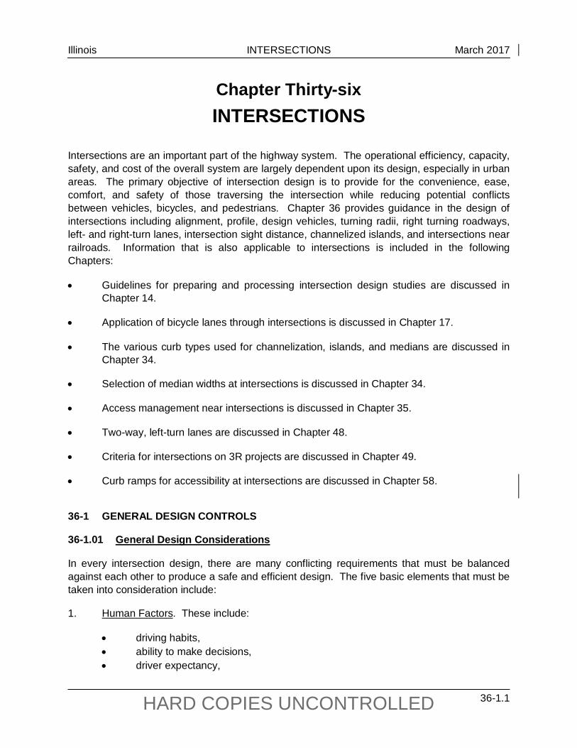
36-1.02 Intersection Components
Figure 36-1.B illustrates several of the components that may be included in a typical intersection.
TYPICAL INTERSECTION COMPONENTS
Figure 36-1.B

Illinois INTERSECTIONS March 2017
36-1.5 HARD COPIES UNCONTROLLED
36-1.03 Intersection Types
36-1.03(a) General
Intersections are usually a three-leg, four-leg, or multi-leg design. Individual intersections may vary in size and shape and may be channelized. The principal design factors that affect the selection of intersection type and its design characteristics are discussed in Section 36-1.01. Selection of the intersection type will be determined on a case-by-case basis.
Multi-leg intersections are those with five or more intersection legs. Where volumes are light and stop control is used, it may be satisfactory to have all intersection legs intersect at a common, all-paved area. At other than minor intersections, safety and efficiency are improved by rearrangements that remove some conflicting movements from the major intersection. This may be accomplished by realigning one or more of the intersecting legs and combining some traffic movements at adjacent subsidiary intersections or, in some cases, making one or more legs one-way departing from the intersection. Wherever practical, avoid using multi-leg intersections.
36-1.03(b) Alternative Intersection Designs
Some nontraditional designs may offer substantial advantages under certain conditions compared to corresponding conventional at-grade intersections or grade-separated diamond interchanges. The FHWA Alternative Intersections/Interchanges: Information Report (AIIR), which can be found on the FHWA website, addresses geometric design features, operational and safety issues, access management, costs, construction sequencing, environmental benefits, and applicability for alternative intersections. The Report provides guidance on the following alternative designs that may provide a unique solution to special situations:
• displaced left-turn intersection, • median U-turn intersection, • quadrant roadway intersection, • restricted crossing U-turn intersection, • double crossover diamond interchange, and • displaced left-turn interchange.
36-1.04 Intersection Spacing
Spacing for unsignalized intersections and driveways will depend on the available stopping sight distance, intersection sight distance, traffic volumes, turning volumes, the addition of turn lanes, turning speeds, access control, and local development. The actual spacing will be determined on a case-by-case basis.
When introducing a new intersection, the designer must ensure that there is sufficient distance between the new and adjacent intersections so that they form distinct intersections. Avoid short distances between intersections, if practical, because they may impede traffic operations. For

Illinois INTERSECTIONS March 2017
36-1.6 HARD COPIES UNCONTROLLED
example, if two intersections are close together, they must be considered as one intersection for signal phasing purposes. To operate safely, each leg of the intersection may require a separate green phase; however, this may reduce the capacity for both intersections.
The need to efficiently move high volumes of traffic, especially during peak periods, is a major consideration in the spacing of signalized intersections. It is important that the signals be synchronized to efficiently move traffic. Figure 36-1.C illustrates the relationship between speed of progression, cycle length, and signalized intersection spacing.
36-1.05 Intersection Alignment
36-1.05(a) Angled Intersections
Highways should intersect at right angles. Intersections at acute angles are undesirable because they:
• restrict vehicular turning movements,
• require additional pavement and channelization for large trucks,
• increase the exposure time for vehicles and pedestrians crossing the main traffic flow, and
• restrict the crossroad sight distance.
Preferably, the angle of intersection should be within 15° of perpendicular. This amount of skew can often be tolerated because the impact on sight lines and turning movements is not significant. Under restricted conditions where obtaining the right-of-way to straighten the angle of intersection would be impractical, an intersection angle up to 30° from perpendicular may be used. Where turning movements are significantly unbalanced, the intersections may be angled to favor the predominant movement. Intersection angles beyond these ranges may warrant more positive traffic control (e.g., all stop, traffic signals) or geometric improvements (e.g., realignment, greater corner sight distance).
Figure 36-1.D illustrates various angles of intersections and potential improvements to the alignment. Avoid using short-radius curves or unnatural travel paths near the intersection simply to reduce the intersection skew.

Illinois INTERSECTIONS March 2017
36-1.7 HARD COPIES UNCONTROLLED
US Customary Cycle
Length (sec)
Posted Speed (mph) 25 30 35 40 45 50 55
Intersection Spacing for Progression (2) 60 1,100 ft 1,320 ft 1,540 ft 1,760 ft 1,980 ft 2,200 ft 2,430 ft 70 1,280 ft 1,540 ft 1,800 ft 2,050 ft 2,310 ft 2,500 ft 2,640 ft 80 1,470 ft 1,760 ft 2,050 ft 2,350 ft 2,640 ft 2,640 ft 2,640 ft 90 1,630 ft 1,980 ft 2,310 ft 2,640 ft 2,640 ft 2,640 ft 2,640 ft 120 2,200 ft 2,640 ft 2,640 ft 2,640 ft 2,640 ft 2,640 ft 2,640 ft
150(1) 2,640 ft 2,640 ft 2,640 ft 2,640 ft 2,640 ft 2,640 ft 2,640 ft Metric
Cycle Length (sec)
Posted Speed (mph) 25 30 35 40 45 50 55
Intersection Spacing for Progression (2) 60 335 m 400 m 470 m 535 m 605 m 670 m 730 m 70 390 m 470 m 550 m 625 m 705 m 760 m 800 m 80 450 m 535 m 625 m 715 m 800 m 800 m 800 m 90 495 m 605 m 705 m 800 m 800 m 800 m 800 m 120 670 m 800 m 800 m 800 m 800 m 800 m 800 m
150(1) 800 m 800 m 800 m 800 m 800 m 800 m 800 m Notes:
1. Represents maximum cycle length for actuated signal if all phases are used.
2. From a practical standpoint when considering progression, the distance between signalized intersections will usually be 2640 ft (800 m) or less. Therefore, the values in the table have been limited to 2640 ft (800 m)
SIGNALIZED INTERSECTION SPACING GUIDELINES
FIGURE 36-1.C

Illinois INTERSECTIONS March 2017
36-1.8 HARD COPIES UNCONTROLLED
Notes: 1. Where there are high volumes of left turns from the major road, avoid using the offset
intersection alignment illustrated in “C.” 2. Revised alignments “C” and “D” are not desirable in agricultural areas with large numbers of
farm vehicles crossing the major road.
REALIGNMENT OF INTERSECTIONS
Figure 36-1.D

Illinois INTERSECTIONS March 2017
36-1.9 HARD COPIES UNCONTROLLED
36-1.05(b) Intersections on Curves
Preferably, all legs of an intersection should be on a tangent section. Where a minor road intersects a major road on a horizontal curve, the geometric design of the intersection becomes significantly more complicated, particularly for sight distance, turning movements, channelization, and superelevation. The following guidelines address horizontal alignment at intersections:
1. Realignment. If relocation of the intersection is not practical, the designer may be able to realign the minor road to intersect the major road perpendicular to a tangent on the horizontal curve; see example “E” in Figure 36-1.D. Although an improvement, this arrangement may still result in difficult turning movements due to superelevation on the major road.
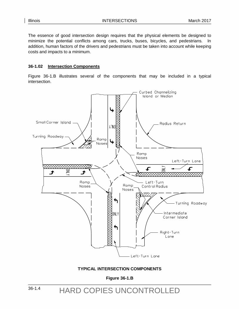
2. Superelevated Mainline. If the mainline is on a horizontal curve, the mainline superelevation rate must be minimized so that slowing or stopped vehicles do not slide across the pavement during wet or icy conditions. Figure 36-1.E provides the criteria for the maximum superelevation rate and rollover criteria that should be used where an important crossroad intersects a superelevated State highway. An important crossroad may be a marked highway, county highway, township road, or town street.
3. Curved Approach. Where a State highway or local road is on a curved alignment and is approaching a stop condition, special consideration is required in the design of the horizontal curvature prior to the intersection. This condition is illustrated in Figure 36-1.F. When designing this type of an approach, consider the following guidelines:
• To design the horizontal curve, assume a design speed 20 mph (30 km/hr) less than the approach speed, but not less than 30 mph (50 km/hr) for design speeds less than or equal to 50 mph (80 km/hr).
• The superelevation rate on the approach curve to an intersection should be limited to a maximum superelevation rate of 5% or less. The objective is to use as flat an alignment as practical with lower superelevation. The preferred design is to maintain a normal crown section through the curve assuming Method 2 distribution of superelevation. The minimum radius should not be less than that permitted for the highway classification. For additional guidance on horizontal curve designs, see Chapter 32.
• Provide a short tangent section prior to the intersection. This will allow for the superelevation runoff to be developed outside of the intersection radius returns.
This procedure recognizes the need to accommodate a reasonable operating speed on a stop-controlled approach, while minimizing the potential for adverse operations on superelevated pavements during snow and ice conditions. Where the curved road is a local facility, design the curvature using the Bureau of Local Roads and Streets’ criteria. With the local roads criteria, the design is dependent on ADT and, in many cases due to the low ADT, the local facility can be designed with a normal crown section.
Illinois INTERSECTIONS March 2017
36-1.10 HARD COPIES UNCONTROLLED
Type of Improvement Category
Maximum Superelevation Rate “e” for Intersections on Curve
Rollover Guidelines
“New Construction” at an important crossroad 4% Desirable Maximum 5% Desirable Maximum
6% Maximum To remain in place with “Reconstruction” at an important crossroad 6% Maximum 7% Desirable Maximum
8% Maximum To remain in place with “Reconstruction” at a minor crossroad 8% Maximum 9% Desirable Maximum
10% Maximum
INTERSECTION WITH SUPERELEVATED MAINLINE
Figure 36-1.E

Illinois INTERSECTIONS March 2017
36-1.11 HARD COPIES UNCONTROLLED
INTERSECTION WITH SUPERELEVATED SIDE ROAD
Figure 36-1.F

Illinois INTERSECTIONS March 2017
36-1.12 HARD COPIES UNCONTROLLED
4. Frontage Road Approach. Where a stop-controlled frontage road approaches a grade separated crossroad, the typical curved alignment may be replaced with a “buttonhook” design; see Figure 36-1.G, to minimize impacts and land acquisitions. This layout is especially suited to those cases where turning traffic between the frontage road and crossroad is light compared to the through traffic on the frontage road.
36-1.05(c) Offset Intersections
In general, 4-leg intersections should be designed such that opposing approaches line up with each other (i.e., there is no offset between opposing approaches). However, this is not always practical. Figure 36-1.H presents a diagram of an intersection with an offset between opposing approaches. Because of possible conflicts with overlapping turning vehicles, offset intersections should only be allowed to remain on low-volume approaches. The following criteria will apply for offset intersection approaches:
1. Maximum Offset. The maximum offset is determined from the application of a taper equal to V:1 (0.6V:1) applied to the intersection width, where V is the design speed in miles per hour (kilometers per hour); see Figure 36-1.H. In restricted locations and where V ≤ 45 mph (70 km/hr), the applied taper may be V2/60 (V2/155). V is selected as follows:
• V = 20 mph (30 km/hr) for stop-controlled approaches.
• V = the roadway design speed for the free-flowing approaches at a stop-controlled intersection.
• V = the roadway design speed for the offset approaches at a signalized intersection.
2. Turning Conflicts. Evaluate the entire intersection for conflicts that may result from turning vehicles at an offset intersection. For example, offsets where the “jog” is to the left may result in significant interference between simultaneous left-turning vehicles.
3. Evaluation Factors. In addition to potential vehicular conflicts, the designer should evaluate the following at existing or proposed offset intersections:
• through and turning volumes; • type of traffic control; • impact on all turning maneuvers; • intersection geometrics (e.g., sight distance, curb/pavement edge radii); and • crash history at existing intersections.
Where existing offset intersections are being considered to remain, the designer should coordinate the intersection design and traffic control requirements with BDE and the district Bureau of Operations.

Illinois INTERSECTIONS March 2017
36-1.13 HARD COPIES UNCONTROLLED
ALTERNATIVE FRONTAGE ROAD INTERSECTION (Buttonhook Design)
Figure 36-1.G

Illinois INTERSECTIONS March 2017
36-1.14 HARD COPIES UNCONTROLLED
Notes: 1. Desirable taper rate is V:1 (0.6V:1), where V = design speed in mph (km/hr). 2. See discussion in Section 36-1.05(c) for more information.
OFFSET INTERSECTION
Figure 36-1.H
Illinois INTERSECTIONS March 2017
36-1.15 HARD COPIES UNCONTROLLED
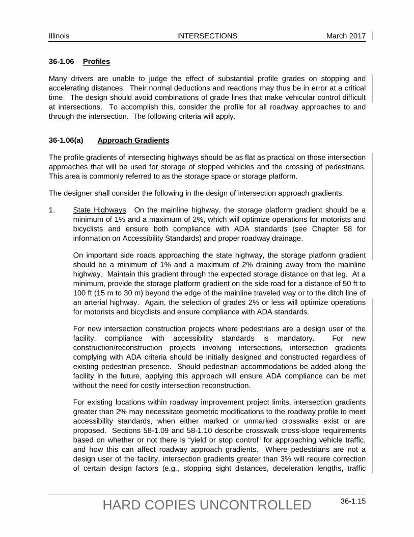
36-1.06 Profiles
Many drivers are unable to judge the effect of substantial profile grades on stopping and accelerating distances. Their normal deductions and reactions may thus be in error at a critical time. The design should avoid combinations of grade lines that make vehicular control difficult at intersections. To accomplish this, consider the profile for all roadway approaches to and through the intersection. The following criteria will apply.
36-1.06(a) Approach Gradients
The profile gradients of intersecting highways should be as flat as practical on those intersection approaches that will be used for storage of stopped vehicles and the crossing of pedestrians. This area is commonly referred to as the storage space or storage platform.
The designer shall consider the following in the design of intersection approach gradients:
1. State Highways. On the mainline highway, the storage platform gradient should be a minimum of 1% and a maximum of 2%, which will optimize operations for motorists and bicyclists and ensure both compliance with ADA standards (see Chapter 58 for information on Accessibility Standards) and proper roadway drainage.
On important side roads approaching the state highway, the storage platform gradient should be a minimum of 1% and a maximum of 2% draining away from the mainline highway. Maintain this gradient through the expected storage distance on that leg. At a minimum, provide the storage platform gradient on the side road for a distance of 50 ft to 100 ft (15 m to 30 m) beyond the edge of the mainline traveled way or to the ditch line of an arterial highway. Again, the selection of grades 2% or less will optimize operations for motorists and bicyclists and ensure compliance with ADA standards.
For new intersection construction projects where pedestrians are a design user of the facility, compliance with accessibility standards is mandatory. For new construction/reconstruction projects involving intersections, intersection gradients complying with ADA criteria should be initially designed and constructed regardless of existing pedestrian presence. Should pedestrian accommodations be added along the facility in the future, applying this approach will ensure ADA compliance can be met without the need for costly intersection reconstruction.
For existing locations within roadway improvement project limits, intersection gradients greater than 2% may necessitate geometric modifications to the roadway profile to meet accessibility standards, when either marked or unmarked crosswalks exist or are proposed. Sections 58-1.09 and 58-1.10 describe crosswalk cross-slope requirements based on whether or not there is “yield or stop control” for approaching vehicle traffic, and how this can affect roadway approach gradients. Where pedestrians are not a design user of the facility, intersection gradients greater than 3% will require correction of certain design factors (e.g., stopping sight distances, deceleration lengths, traffic

Illinois INTERSECTIONS March 2017
36-1.16 HARD COPIES UNCONTROLLED
signal timing) to produce operating conditions as equivalent as practicable to those on level highways.
Any gradient through an intersection must reflect the practicalities of matching the basic profiles of the intersecting roadways and shoulders. When desirable intersection approach gradients, as discussed above, cannot be achieved due to terrain, right-of-way, or other important concerns on any project defined as an alteration of the facility, see Section 58-1.01, a design exception and/or a request for a maximum extent practicable determination (MEP) may be necessary; see Chapter 31.
2. Local Highways. For local roads and entrances to the mainline highway, provide a profile that will drain away from the mainline highway. Where a local facility (e.g., township road, county highway, low-volume town street) intersects a State highway on a tangent section, the side-road storage platform gradient may be a maximum of 4% draining away from the State highway, unless a marked or unmarked crosswalk exists or is proposed across the storage platform of the facility. For these locations, approach gradients steeper than 2% may necessitate geometric modifications to the roadway profile to meet accessibility standards; see Section 58-1.09.
3. Intersection Rollover. The algebraic difference between mainline highway and side road should not exceed the rollover guidelines described in Figure 36-1.E.
4. Grade Lines. The principles for coordinating the horizontal and vertical alignment discussed in Chapter 33 are also applicable to vertical profiles through intersections. In addition, do not place intersections on or near crest vertical curves unless the vertical curve is flat enough for the intersection pavement to be seen assuming decision sight distance criteria.
36-1.06(b) Cross-Section Transitions
One or more of the approaching legs of an intersection may need to be transitioned (or warped) to meet the cross section of the two crossing roads. The following applies:
1. Stop Controlled. Where the minor road is stop controlled, maintain the profile and cross section of the major road through an intersection and transition the cross slope of the stop-controlled roadway to match the major road cross slope and profile.
2. Signalized Intersection. At signalized intersections, or potentially signalized intersections, transition the cross section of the minor road to meet the profile and cross slope of the major road. Where compromises are necessary between two major roadways, provide the smoother riding characteristics to the roadway with the higher traffic volumes and operating speeds.
3. Transition Rates. Where one or both intersecting roadways are transitioned, the designer must determine the length and rate of transition from the typical section to the modified section. Desirably, design the transition to meet the general principles of superelevation transition which apply to that roadway (i.e., open-roadway or low-speed

Illinois INTERSECTIONS March 2017
36-1.17 HARD COPIES UNCONTROLLED
urban street conditions); see Section 32-3. When these criteria are applied to intersection transition rates, the applied design speed is typically:
• 20 mph (30 km/hr) below the design speed but not less than 30 mph (50 km/hr) for a stop-controlled roadway,
• the highway design speed for a free-flowing roadway, or
• the highway design speed on each roadway of a signalized intersection.
At a minimum and consistent with field conditions, transition the approach pavements of an urban intersection within the curb or radius returns and for rural intersections within a distance of 50 ft (15 m).
36-1.06(c) Profiles at Intersections
Where the cross section of the minor road is warped to meet the major road, provide a vertical curve between the side road approach gradient and the mainline pavement; see Figure 36-1.I. The following vertical curve options are presented in order from the most desirable to the least desirable:
1. Vertical Curves (SSD). The criteria for stopping sight distance as described in Chapter 33 should be used for the vertical curve. Use the design speed discussed in Section 36-1.06(b) to design the vertical curve.
2. Sag Vertical Curves (Minimum Comfort). Under restricted conditions where the SSD criteria is not practical, the sag vertical curves at intersection approaches may be based on the following formulas:
)V1.0( =K 2 (US Customary) ).034V0( =K 2 (Metric)
KA = L where: K = the horizontal distance in feet (meters) needed to produce a 1%
change in the gradient along the curve
A = algebraic difference between the two tangent grades, %
V = design speed, mph (km/hr)
L = length of vertical curve, ft (m)
3. Angular Breaks. At stop-controlled intersections, angular breaks are typically provided when warping the cross section of the minor approach to meet the mainline cross section. Figure 36-1.I presents a schematic of vertical profiles through an intersection. Figure 36-1.E provides the maximum rollover guidelines which are also applicable for changes in angular breaks.
4. Driveways. For driveway profiles with and without sidewalks, the designer should refer to the IDOT Policy on Permits for Access Driveways to State Highways (92 Ill. Admin. Code 550).

Illinois INTERSECTIONS March 2017
36-1.18 HARD COPIES UNCONTROLLED
Not
es:
Des
irabl
y, th
e m
inor
roa
d pr
ofile
sho
uld
tie in
to th
e m
ainl
ine
trave
l lan
e cr
oss
slop
e; h
owev
er, w
here
the
min
or r
oad
is s
top
cont
rolle
d, it
will
be a
ccep
tabl
e fo
r the
min
or ro
ad p
rofil
e to
tie
into
the
mai
nlin
e sh
ould
er c
ross
slo
pe.
Act
ual f
ield
con
ditio
ns
will
dete
rmin
e th
e fin
al d
esig
n
See
Item
1 in
Sec
tion
36-1
.06(
a) fo
r sto
rage
pla
tform
gra
dien
ts.
At s
igna
lized
inte
rsec
tions
, the
mos
t des
irabl
e cr
oss
slop
e op
tion
will
be to
tran
sitio
n al
l app
roac
h le
gs in
to a
pla
nar
surfa
ce
thro
ugh
the
inte
rsec
tion
and
to li
mit
the
cent
erlin
e ro
llove
r on
the
mai
nlin
e to
2%
- 3%
.
For a
sig
nal c
ontro
lled
min
or ro
ad d
esce
ndin
g fro
m th
e m
ainl
ine,
mai
ntai
n th
e tra
vel l
ane
cros
s sl
ope
of th
e m
ainl
ine
road
way
th
roug
h th
e le
ngth
of t
he s
tora
ge p
latfo
rm.
VER
TIC
AL
PRO
FILE
S O
F IN
TERS
ECTI
NG R
OAD
S
Figu
re 3
6-1.
I

Illinois INTERSECTIONS March 2017
36-1.19 HARD COPIES UNCONTROLLED
36-1.06(d) Drainage
Evaluate the profile and transitions at all intersections for impacts on drainage. This is especially important for channelized intersections on curves and grades. This may require the designer to check superelevation transition lengths to ensure flat sections are minimized. Low points on approach roadway profiles should be beyond a raised corner island to prevent water from being trapped and causing ponding.
36-1.07 Intersection Capacity Analysis
Capacity analysis influences several geometric design features including the number of approach lanes, auxiliary lanes, lane widths, channelization, and number of departure lanes. In addition, this analysis in conjunction with the Illinois Manual on Uniform Traffic Control Devices will determine whether an intersection may need to be signalized or stop controlled. Any considered change in traffic control should be reviewed with the district Bureau of Operations for concurrence.
It is important that the level of service for a signalized intersection be calculated for each lane group (a lane group may be one or more movements), each intersection approach, and the intersection as a whole. Level of service criteria are provided in the geometric design tables in Part V, Design of Highway Types, of the BDE Manual.
Once the minimum level of service has been selected and design traffic volumes are determined, use the Highway Capacity Manual and the Highway Capacity Software (HCS) to perform the detailed capacity analyses. Ensure that data used in the analyses are applicable for the intersection (i.e., do not assume the program default values are automatically applicable for the intersection). Other capacity and signal analysis programs may be used provided they are approved for use by the BDE. To be eligible for approval, the output results must be comparable to the HCS.
If the intersection is part of a traffic signal system, check the intersection design with an approved traffic progression program. These programs analyze all signalized intersections in the system to determine the overall capacity of the system. Also, see Figure 36-1.C.
36-1.08 Design Vehicles
36-1.08(a) Types
The design vehicle affects the radius returns, left-turn radii, lane widths, median openings, turning roadways, and sight distances at an intersection. The basic design vehicles used by IDOT for intersection design are:
• P Passenger car; includes vans and pickup trucks.
• S-BUS-40 (S-BUS-12) 84-passenger school bus.

Illinois INTERSECTIONS March 2017
36-1.20 HARD COPIES UNCONTROLLED
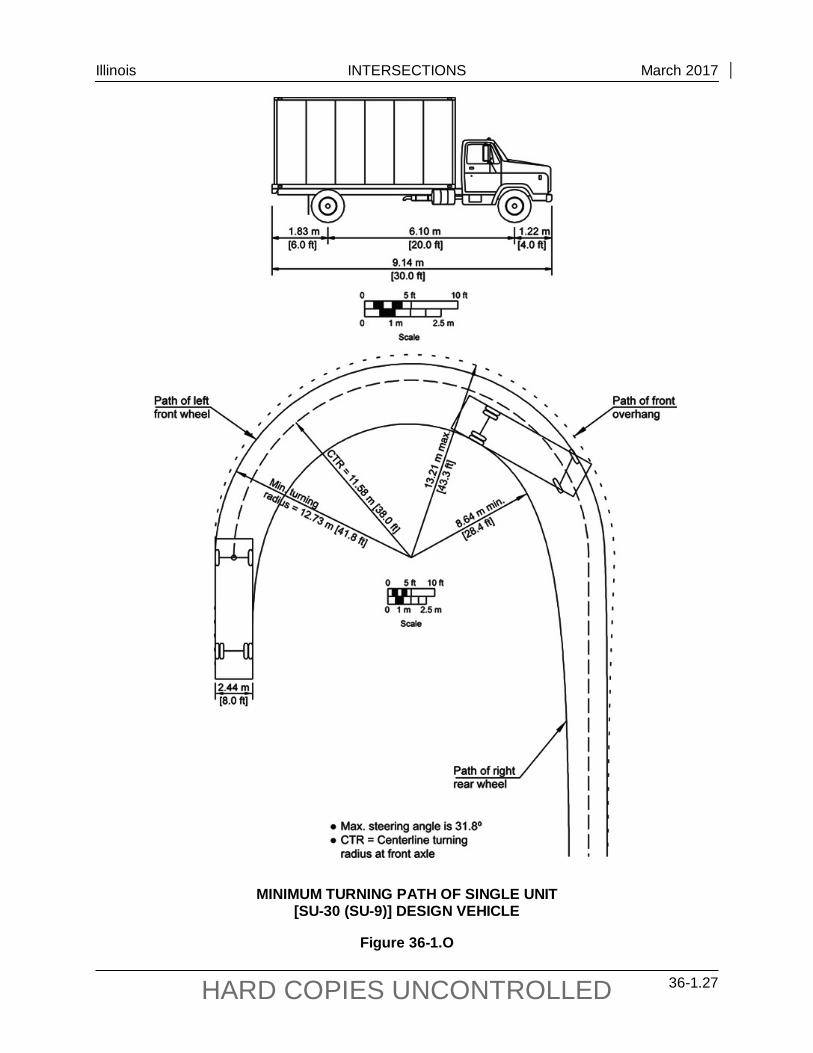
• SU-30 (SU-9) Single-unit truck with an overall vehicle length of 30 ft.
• WB-40 (WB-12) Tractor/Semitrailer combination with an overall wheelbase of 40 ft (12.2 m).
• WB-50 (WB-15) Tractor/Semitrailer combination with an overall wheelbase of 50 ft (15.2 m).
• WB-55 (WB-17) Tractor/Semitrailer combination with an overall wheelbase of 55 ft (16.8 m).
• WB-65/67 (WB-20) Tractor/Semitrailer combination with an overall wheelbase of 65 ft or 67 ft (20.4 m).
• WB-67D (WB-20D) Tractor/Semitrailer/Trailer combination with an overall wheelbase of 67 ft (20.4 m).
• P/T Recreational vehicle, car, and camper trailer.
Figure 36-1.J illustrates the turning characteristics for a typical tractor/semitrailer design vehicle and definitions for terms that make up the characteristics. Figure 36-1.K shows the dimensions of commonly used truck tractors. For IDOT’s purposes, the long haul tractors are used for the WB-65 and WB-67 design vehicles. The city and short haul tractors are used for the remaining multi-unit design vehicles. Figure 36-1.L shows the relationship between the maximum steering angle, effective wheelbase of a tractor, and the centerline turning radius on which the turning paths for combination trucks is based.
Figures 36-1.M through 36-1.U provide vehicular dimensions and turning templates for typical design vehicles. The turning path parameters for the design vehicles in Figures 36-1.M through 36-1.U may vary from the software used for intersection and other types of geometric layout. Vehicle turning software is periodically updated by the software manufacturers to be current with industry standards, while the turning path parameters for the design vehicles are meant to visually represent a turning path. The minimum turning radii shown in the figures are for turns less than 10 mph (15 km/hr).
36-1.08(b) Selection
Figure 36-1.V presents the recommended design vehicles at intersections based on the functional classification of the intersecting highways which the vehicle is turning from and onto. Figure 36-1.W presents the recommended truck type that should be used based on the Illinois “Designated State Truck Route System.” Chapter 43 further discusses the National Truck Network. The design vehicles shown in Figures 36-1.V and/or 36-1.W are for new construction and reconstruction projects. For 3R projects, the design vehicle will be site specific, and it may be a design vehicle with a less restrictive turning radius than those for new construction and reconstruction projects.
Illinois INTERSECTIONS March 2017
36-1.21 HARD COPIES UNCONTROLLED
In addition to Figures 36-1.V and 36-1.W, use the following guidelines when selecting a design vehicle:
1. Minimum Designs. The SU-30 and/or S-BUS-40 design vehicles are generally the smallest vehicles used in the design of State highway intersections. This design reflects that, even in residential areas, garbage trucks, delivery trucks, and school buses will be negotiating turns with some frequency. Rural intersections which may serve school bus traffic should, at a minimum, accommodate a turning school bus without encroachment onto opposing lanes travel. Intersections of State highways with suburban residential streets should also accommodate, at a minimum S-BUS-40. Encroachment onto opposing lanes travel is permitted, but not desirable. Urban intersections only need to accommodate design vehicles that are expected to use that intersection; see Section 36-2.01 for further discussion on encroachment.
2. Recreational Areas. Recreational areas typically will be designed using the SU design vehicle. This reflects that service vehicles are typically required to maintain the recreational area. Under some circumstances the passenger car with a trailer (P/T) may be the appropriate design vehicle (e.g., campground areas, boat launches).
3. Mixed Use. Some portions of an intersection may be designed with one design vehicle and other portions with another vehicle. For example, it may be desirable to design physical characteristics (e.g., corner islands) for the WB-67 (WB-20) truck but provide painted channelization for the SU design vehicle.
4. Turning Template. The intersection design and layout should be checked with an approved computer simulated turning template program or with an actual turning template.
Federal law prohibits limiting the overall length of tractor/semitrailer and tractor/semitrailer/trailer combinations on the National Network; see Section 43-5 for a discussion on the National Network. Thus tractor/semitrailer and tractor/semitrailer/trailer combinations longer than WB-67 are allowed on some Illinois roads without permits, however unless vehicle surveys indicate a need for designing for larger vehicles, designing for WB-67’s is adequate for the facilities shown in Figure 36-1.V.
Illinois Statutes applied the Federal law to all Class I highways. The Illinois Statutes also does not have an overall length limits on Class II highways, but limits the length from the front axle to the rear axle to 65 ft (WB-65) on Class II highways.
36-1.09 Pedestrians and Bicyclists
Safe and convenient movement of pedestrians and bicyclists through the intersection needs to be considered in the design of an intersection. However, this often causes conflicting objectives in the overall design of an intersection. Wider intersection designs to accommodate the design vehicle significantly increase the crossing distance for pedestrians. At signalized intersections, longer crossing times and conflicts with turning vehicles can significantly affect the overall
Illinois INTERSECTIONS March 2017
36-1.22 HARD COPIES UNCONTROLLED
capacity of the intersection. To reduce these problems, the geometric layout of the intersection may need to be revised, refuge islands included within the intersection, special turn lanes added for bicyclists, or other factors included in the design.
Chapter 58 discusses the application of curb ramps at intersections for individuals with disabilities. Chapter 17 provides several applications for accommodating bicycle lanes and pedestrians through an intersection.
36-1.10 Pavement Markings/Reflectorized Markers
Use the current edition of the Bureau of Operation’s Policies and Procedures Manual to design the pavement markings and crosswalks at intersections. Chapter 57 provides general guidelines for the placement of pavement markings and reflectorized markers.
36-1.11 Intersection Lighting
The primary objective of highway lighting is to enhance highway safety. Intersection lighting enables the driver to determine the geometry and condition of the intersection at extended distances thereby simplifying the driver task. This in turn increases driver comfort and reduces fatigue which may contribute to highway safety. Chapter 56 discusses the warrants and design criteria for highway and intersection lighting.
36-1.12 Bus Turnouts
For design of bus turnouts near intersections, see Chapter 58.

Illinois INTERSECTIONS March 2017
36-1.23 HARD COPIES UNCONTROLLED
Definitions:
1. Turning Radius. The circular arc formed by the turning path radius of the front outside tire of a vehicle. This radius is also described by vehicular manufacturers as the “turning curb radius.”
2. Centerline Turning Radius (CTR). The turning radius of the centerline of the front axle of a vehicle with its steering wheels at the steering lock position.
3. Offtracking. The difference in the paths of the front and rear wheels of a tractor/semitrailer as it negotiates a turn. The path of the rear tires of a turning truck does not coincide with that of the front tires. This effect is shown in the drawing above.
4. Swept Path Width. The amount of roadway width that a truck covers in negotiating a turn and is equal to the amount of off-tracking plus the width of the tractor unit. The most significant dimension affecting the swept path width of a tractor/semitrailer is the distance from the kingpin to the rear trailer axle or axles. The greater this distance is, the greater the swept path width.
5. Steering Angle. The average of the angles made by the left and right steering wheels with the longitudinal axis of the vehicle when the wheels are turned to their maximum angle. The Maximum angle controls the minimum turning radius of the vehicle.
6. Tractor/Trailer Angle. The angle between adjoining units of a tractor/semitrailer when the combination unit is placed into a turn. This angle is measured between the longitudinal axes of the tractor and trailer as the vehicle turns. The maximum tractor/trailer angle occurs when a vehicle makes a 180° turn at the minimum turning radius and is reached slightly beyond the point where a maximum swept path width is achieved.
TURNING CHARACTERISTICS OF A TYPICAL
TRACTOR-SEMITRAILER COMBINATION DESIGN VEHICLE
Figure 36-1.J

Illinois INTERSECTIONS March 2017
36-1.24 HARD COPIES UNCONTROLLED
DIMENSIONS OF COMMONLY USED TRUCK TRACTORS
FIGURE 36-1.K
COMPUTATION METHOD FOR DETERMININGTHE CTR FOR TRACTOR-SEMITRAILER COMBINATION TRUCKS
FIGURE 36-1.L

Illinois INTERSECTIONS March 2017
36-1.25 HARD COPIES UNCONTROLLED
MINIMUM TURNING PATH OF PASSENGER CAR (P) DESIGN VEHICLE
Figure 36-1.M

Illinois INTERSECTIONS March 2017
36-1.26 HARD COPIES UNCONTROLLED
*Note: The 84-passenger school bus is the largest school bus presently manufactured.
MINIMUM TURNING PATH OF 84-PASSENGER SCHOOL BUS (S-BUS) DESIGN VEHICLE
Figure 36-1.N
Illinois INTERSECTIONS March 2017
36-1.27 HARD COPIES UNCONTROLLED
MINIMUM TURNING PATH OF SINGLE UNIT [SU-30 (SU-9)] DESIGN VEHICLE
Figure 36-1.O

Illinois INTERSECTIONS March 2017
36-1.28 HARD COPIES UNCONTROLLED
TURNING PATH OF TRACTOR/SEMITRAILER [WB-40 (WB-12)] DESIGN VEHICLE
Figure 36-1.P
Illinois INTERSECTIONS March 2017
36-1.29 HARD COPIES UNCONTROLLED
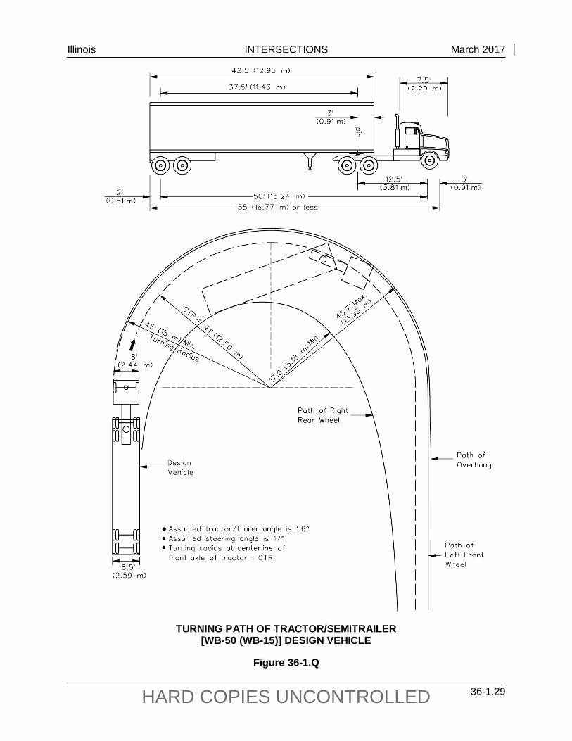
TURNING PATH OF TRACTOR/SEMITRAILER [WB-50 (WB-15)] DESIGN VEHICLE
Figure 36-1.Q

Illinois INTERSECTIONS March 2017
36-1.30 HARD COPIES UNCONTROLLED
*Note: Presently, trailers are manufactured in lengths of 40 ft (12.19 m), 42.5 ft (12.95 m), 45 ft
(13.72 m), 48 ft (14.63 m), and 53 ft (16.16 m).
TURNING PATH OF TRACTOR/SEMITRAILER [WB-55 (WB-17)] DESIGN VEHICLE
Figure 36-1.R

Illinois INTERSECTIONS March 2017
36-1.31 HARD COPIES UNCONTROLLED
Note: The WB-67 is shown. A shorter wheelbase vehicle, the WB-65, can be created by moving the tandem wheel assembly on the trailer forward by 2 ft.
*Note: Presently, trailers are manufactured in lengths of 40 ft (12.19 m), 42.5 ft (12.95 m), 45 ft (13.72
m), 48 ft (14.63 m), and 53 ft (16.16 m).
TURNING PATH OF TRACTOR/SEMITRAILER [WB-65 AND WB-67 (WB-20)] DESIGN VEHICLE
Figure 36-1.S

Illinois INTERSECTIONS March 2017
36-1.32 HARD COPIES UNCONTROLLED
TURNING PATH OF TRACTOR/SEMITRAILER/TRAILER [WB-67D (WB-20D)] DESIGN VEHICLE
Figure 36-1.T

Illinois INTERSECTIONS March 2017
36-1.33 HARD COPIES UNCONTROLLED
MINIMUM TURNING PATH OF PASSENGER CAR AND TRAILER (P/T) DESIGN VEHICLE
Figure 36-1.U

Illinois INTERSECTIONS March 2017
36-1.34 HARD COPIES UNCONTROLLED
For Turn Made Design
Vehicle (1)(2)(3) From Onto
Freeway Ramp Other Facilities WB-67 (WB-20)
Other Facilities Freeway Ramp WB-67 (WB-20)
Arterial or SRA(4)
Arterial/SRA Collector
Local Local (Residential)
WB-65 (WB-20) WB-55 (WB-17) WB-50 (WB-15)
SU*
Collector
Arterial/SRA Collector
Local Local (Residential)
WB-55 (WB-17) WB-55 (WB-17) WB-50 (WB-15)
SU*
Local
Arterial/SRA Collector
Local Local (Residential)
WB-50 (WB-15) WB-50 (WB-15)
SU* SU
Local (Residential)
Arterial/SRA Collector
Local Local (Residential)
SU* SU* SU SU
*With encroachment, a WB-50 (WB-15) vehicle should physically be able to make the turn.
Notes:
1. Use this figure for new construction and reconstruction projects.
2. A smaller design vehicle may be considered as a design exception after an investigation of conditions and with justification.
3. For 3R projects, the design vehicle will be site specific with justification.
4. SRA is a Strategic Regional Arterial route.
SELECTION OF DESIGN VEHICLE AT INTERSECTIONS (Functional Classification)
Figure 36-1.V

Illinois INTERSECTIONS March 2017
36-1.35 HARD COPIES UNCONTROLLED
Type of Truck Route Design Vehicle Maximum Length
of Trailer Allowed (m)
Maximum Length Kingpin to Center
Rear Axle (m)
Class I WB-67 (WB-20) 53′ (16.16 m) 45.5′ (13.87 m)
Class II WB-65 (WB-20) 53′ (16.16 m) 45.5′ (13.87 m)
Class III WB-55 (WB-17) 53′ (16.16 m) 42.5′ (12.96 m)
Other State Highway (OSH) WB-55 (WB-17) 53′ (16.16 m) 42.5′ (12.96 m)
Local Roads and Streets WB-50 (WB-15) Not Specified Not Specified Illinois Statutes allow additional access off designated truck routes under different conditions. These are defined as follows:
1. Section 43-1.06 defines Class I, Class II, and Class III Highways as used in the Illinois Vehicle Code.
2. Any tractor/semitrailer and tractor/semitrailer/trailer vehicle operating on a Class I truck route shall have access onto any street or highway for a distance of 1 mile (1.61 km) from a Class I highway to load and unload and to allow the driver to obtain food, fuel, rest, or repairs. However, some local highway authorities may post truck restrictions altering this provision. Under this condition, the combination truck units allowed access off the Class I truck route may be up to 8 ft 6 in. (2.59 m) wide with a 53 foot (16.16 m) long trailer (28.5 ft trailer for tractor/semitrailer/trailer combinations).
3. Any tractor/semitrailer vehicle operating on a designated State highway (Class I, II, III, or Other State Highways) shall have access on another designated State highway for a distance of 5 miles (8.05 km) on such streets or highways to load and unload and to allow the driver to obtain food, fuel, rest, or repairs.
4. If local authorities designate any street or highway for the same large vehicles and the same uses as stated above, such large vehicles may also use these locally designated highways as truck routes. However, these large vehicles are prohibited from using all other streets and highways under local jurisdiction unless an exception is applicable. An exception would be applicable on a local highway where a combination truck unit is within 5 miles (8.05 km) of a designated truck route and where no restricted weight limit is posted on the local highway. In such cases, the combination truck unit may be up to 8 ft 6 in. (2.59 m) wide, and have an overall length of 65 feet (19.82 m).
The statutes referred above do not imply geometric components such as intersection turn radii or driveway aprons be provided to accommodate trucks without encroachment.
DESIGN VEHICLE SELECTION (Designated State Truck Route System)
Figure 36-1.W


Illinois INTERSECTIONS December 2014
36-2.1 HARD COPIES UNCONTROLLED
36-2 TURNING RADII
Turning radii treatments for intersections are important design elements in that they influence the operation, safety, and construction costs of the intersection. The designer must ensure that the proposed design is compatible with the expected intersection operations.
36-2.01 Design for Right-Turning Vehicles
The following sections present several basic parameters the designer needs to consider in determining the proper pavement edge/curb line for right-turning vehicles.
36-2.01(a) Design Vehicle
Section 36-1.08 discusses the selection of the applicable design vehicle for different intersections. These vehicles are used to determine the pavement edge or curb line. Note that the design vehicle will determine the turning width, vehicular path width or swept-path width. The assumed speed of the vehicle is less than 10 mph (15 km/hr).
36-2.01(b) Inside Clearance
Desirably, the selected design vehicle will make the right turn while maintaining approximately a 2 ft (600 mm) clearance from the pavement edge or face of curb.
36-2.01(c) Encroachment
To determine the amount of acceptable encroachment, the designer should evaluate several factors. These would include traffic volumes, one-way or two-way operations, urban/rural location, and the type of traffic control. For turns made onto local facilities, desirably the selected design vehicle will not encroach into the opposing travel lanes. However, this is not always practical or cost effective in urban areas. The designer must evaluate these encroachment conditions against the construction and right-of-way impacts and the effect on the pedestrian crosswalk distance. If these impacts are significant, and if through and/or turning volumes are relatively low, the designer may consider accepting some encroachment of the design vehicle into opposing lanes; see Figure 36-2.D.
The encroachment allowed into adjacent lanes of the road or street onto which the turn is made will depend on the following:
1. Urban. No encroachment should be allowed into opposing lanes for a right-turning vehicle from a side road or street onto a State route.
2. Rural. For rural intersections, the selected design vehicle should not encroach into the opposing lanes of traffic.

Illinois INTERSECTIONS December 2014
36-2.2 HARD COPIES UNCONTROLLED
3. Multilane Highways. If there are two or more lanes of traffic in the same direction on the road onto which the turn is made, the selected design vehicle can occupy both travel lanes. Desirably, the right-turning vehicle will be able to make the turn while remaining entirely in the right through lane; see Figure 36-2.C.
All intersections of two designated State truck routes should be checked to see if the WB-65 (WB-20) design vehicle can physically make the right turn without backing up and without impacting curbs, parked cars, utility poles, mailboxes, traffic control devices, or any other obstructions, regardless of the selected design vehicle or allowable encroachment.
36-2.01(d) Parking Lanes/Shoulders
At many intersections, parking lanes and/or shoulders will be available on one or both approach legs. This additional roadway width may be carried through the intersection. The following will apply:
1. Parking Lanes. Under restricted conditions, the designer may take advantage of shoulder and/or parking lane to ease the problems of large vehicles turning right at intersections with small radius returns. It will be necessary to restrict the parking a significant distance from the intersection. This area should be delineated with striped pavement markings. Parking should be removed from the intersection according to the ILMUTCD.
2. Paved Shoulders. At rural intersections, it may be preferable to continue a paved shoulder throughout the radius return. If a shoulder width transition is required, design it according to Figure 36-2.A.
3. Curbing. If certain conditions such as drainage requirements, restricted right-of-way, greater delineation, or the desire to minimize off-tracking warrant the use of curbing along the radius return at rural intersections, terminate the curbing at the shoulder edge and transition the curb height as indicated in Figure 36-2.A. Where posted speeds are 50 mph or greater, use a mountable type curb.
36-2.01(e) Pedestrian Considerations
The larger the right-turning radius, the farther pedestrians must walk across the street. This is especially important to persons with disabilities. Therefore, the designer must consider the number and type of pedestrians using an intersection when determining the edge of pavement or curb line design. This may lead to a decision to design a right-turn corner island (small or intermediate) for use as a pedestrian refuge.

Illinois INTERSECTIONS December 2014
36-2.3 HARD COPIES UNCONTROLLED
*Note: Only use M-type curb on corner islands.
SHOULDER/CURB AND GUTTER RADIUS RETURN TRANSITIONS
Figure 36-2.A

Illinois INTERSECTIONS December 2014
36-2.4 HARD COPIES UNCONTROLLED
36-2.01(f) Types of Right-Turn Designs
Once the designer has determined the basic right-turning parameters (e.g., design vehicle, amount of allowable encroachment, inside clearance), it will be necessary to select the type of turning design for the curb return or pavement edge which will meet these criteria and will fit the intersection constraints.
The simple radius is the easiest to design and construct. However, two-centered or three-centered curves provide a better fit to the transitional turning paths of tractor/semitrailer design vehicles. Because the WB-67, WB-55, or WB-50 (WB-20, WB-17, or WB-15) trucks are allowed on all State highways, the Department has determined that two-centered or three-centered curves are desirable at all major intersections. Note that using these curves may require a corner island.
Some of the advantages of the two-centered and three-centered curves as compared to the simple radius design include:
• When accommodating a specific design vehicle, they require less intersection pavement than a simple radius design, and especially for angles of turn greater than 90°. For large vehicles, a simple radius is often an unreasonable design unless a corner island is used and, in effect, a turning roadway is provided.
• There are less right-of-way impacts at the intersection corners.
• A simple radius results in greater distances for pedestrians to cross the intersection.
36-2.01(g) Stop Bar Locations
Stop bar locations should be checked against the criteria in the ILMUTCD at wide throat intersections. This is especially important where no corner island is used.
36-2.01(h) Turning Template(s)
To determine the preliminary right-turn design, the designer should use the applicable turning template for the selected design vehicle and speed. Check the final intersection design with the applicable turning templates or with a computer simulated turning template program. If computer simulation is used to determine right-turn design, include the printout with the intersection design study.
36-2.01(i) Summary
Figure 36-2.B illustrates the many factors that should be evaluated in determining the proper design for right-turns movements at intersections. In summary, the following procedure applies:
1. Select the design vehicle (Section 36-2.01(a)).
2. Determine the acceptable inside clearance (Section 36-2.01(b)).

Illinois INTERSECTIONS December 2014
36-2.5 HARD COPIES UNCONTROLLED
SUMMARY OF RIGHT-TURN DESIGN ISSUES
Figure 36-2.B 3. Determine the acceptable encroachment (Section 36-2.01(c)).
4. Consider the benefits of any parking lanes or shoulders (Section 36-2.01(d)).
5. Consider impacts on pedestrians (Section 36-2.01(e)).
6. Select the type of right-turning treatment (Section 36-2.01(f)).
7. Check the location of the stop bar (Section 36-2.01(g)).
8. Check all proposed designs with the applicable vehicular turning templates or computer simulated turning template program (Section 36-2.01(h)).
Revise the design as necessary to accommodate the right-turning vehicle or determine that it is not practical to meet this design because of adverse impacts.

Illinois INTERSECTIONS December 2014
36-2.6 HARD COPIES UNCONTROLLED
36-2.01(j) Local Street Reconstruction
When reconstructing an arterial, the designer often must maintain the existing width on the local street. Figure 36-2.C illustrates the turning path for an SU-30 design vehicle turning out of an existing local street with a 30 ft (9 m) radius. Figure 36-2.D illustrates the turning path for an SU -30 design vehicle turning onto an existing local street.
36-2.02 Corner Islands
In general, the use of corner islands is discouraged. However at some intersections, it may be desirable to provide a directional or corner island to direct drivers. This may be especially advantageous where a tractor/semi-trailer is used as the design vehicle and/or at oblique angle crossing intersections. The corner island may also be used for locating traffic control devices.
Corner islands may also function as refuge islands to aid and protect pedestrians who cross a wide roadway. Corner islands may be required for pedestrians where complex signal phasing is used, and they may permit the use of two-stage crossings. This may enhance traffic signal efficiency by allowing a reduction in the time allocated for pedestrian movements.
The type and size of triangular or corner islands will vary according to the angle of intersection, design vehicle, right-turn operation, and available right-of-way. Figure 36-2.E illustrates the typical designs for corner islands. Also consider the following:
1. Island Sides. The sides of the island should not be less than 12 ft (3.6 m) and, preferably 15 ft (4.5 m), after rounding the corners. If traffic signal posts are installed within the island, the sides of the island should be 30 ft (9.0 m) or greater.
2. Island Size. The minimum island size for rural areas is 100 ft2 (9.5 m2). For urban islands, the island area typically should be 75 ft2 (7.0 m2) but not less than 50 ft2 (4.7 m2). The island area includes the concrete median surface and the top of the curb.
3. Flush or Raised-Curb. For proper delineation of corner islands, under all conditions (e.g., nighttime, rain, fog, snow), the raised-curb design is preferable.
4. Curbing. Only use the M-type curb on corner islands. Also consider the following:
a. Use M-6 (M-15) curb on islands that are located adjacent to a highway with speeds of 45 mph (70 km/hr) or less.
b. Use M-4 (M-10) curb on islands that are located adjacent to high-speed traffic (50 mph (80 km/hr) or greater). However, use M-6 (M-15) curb on islands where traffic signal supports, sign truss supports, or any other post with a foundation generally larger than a standard highway sign are present. Note that a stop sign is a standard highway sign.
c. Use M-6.06 (M-15.15) or M-4.06 (M-10.15) CC&G on all sides of islands where the island is offset the shoulder width from the edge of the traveled way.

Illinois INTERSECTIONS December 2014
36-2.7 HARD COPIES UNCONTROLLED
RECONSTRUCTION OF LOCAL RESIDENTIAL STREET INTERSECTION AT MULTILANE ARTERIAL ROUTE
(Right Turn Out of SU Truck)
Figure 36-2.C
Notes: 1. Figure indicates restricted cross
section on arterial route. 2. Assumed steering angle of truck is
31.9°. 3. Turning radius of truck at centerline
of front axle = CTR. 4. Corner radius = 30 ft (9.0 m).
Illinois INTERSECTIONS December 2014
36-2.8 HARD COPIES UNCONTROLLED
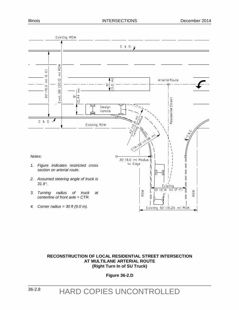
RECONSTRUCTION OF LOCAL RESIDENTIAL STREET INTERSECTION AT MULTILANE ARTERIAL ROUTE
(Right Turn In of SU Truck)
Figure 36-2.D
Notes: 1. Figure indicates restricted cross
section on arterial route. 2. Assumed steering angle of truck is
31.9°. 3. Turning radius of truck at
centerline of front axle = CTR. 4. Corner radius = 30 ft (9.0 m).

Illinois INTERSECTIONS December 2014
36-2.9 HARD COPIES UNCONTROLLED
DETAILS OF CORNER ISLANDS
Figure 36-2.E
Notes: 1. , , - designates a specific corner of island. 2. Ramp the and noses of curbed corner
islands unless the curb function is for the protection of pedestrians, signals, light standards, or sign truss supports.
3. See the IDOT Highway Standards for
details of ramping noses. 4. All corner radii are to the face of curb at
flowline. Show “W” values on IDS. 5. * These dimensions are controlled by the
minimum area requirements of the island, whereas “W” is a required dimension.
6. Dimensions in parentheses are in mm
unless otherwise noted.
Illinois INTERSECTIONS December 2014
36-2.10 HARD COPIES UNCONTROLLED
5. Island Offsets. On streets with outside curb and gutter, offset the corner island from the edge of the traveled way according to Figure 36-2.E. In rural areas or for facilities with shoulders, the corner island is offset the shoulder width, but not greater than 8 ft (2.4 m); see Figure 36-2.F. If a right-turn deceleration lane is provided on the facility, then offset the corner island at least 8 ft (2.4 m).
36-2.03 Turning Roadways
Where the inner edges of pavements for right turns at intersections are designed to accommodate tractor/semi-trailer combinations or where the desired design permits passenger vehicles to turn at speeds of 15 mph (25 km/hr) or greater, the pavement area at the corner of the intersection may become excessively large for proper control of traffic. To avoid this, a corner triangle island is used and the connecting roadway between the two intersection legs is defined as a turning roadway.
36-2.03(a) Guidelines
The need for a turning roadway will be determined on a case-by-case basis. The designer should consider the following guidelines in determining the need for a turning roadway:
1. Trucks. A turning roadway is usually required when the selected design vehicle is a tractor/semitrailer combination.
2. Island Type and Size. Desirably, the island size should be at least 100 ft2 (10 m2). At a minimum, the island should be at least 100 ft2 (9 m2) in rural areas and 50 ft2 (4.5 m2) in urban areas; see Figure 36-2.E.
3. Level of Service. A turning roadway can often improve the level of service through the intersection. At signalized intersections, a turning roadway with a free-flow acceleration lane may significantly improve the capacity of the intersection by removing the right-turning vehicles from the signal timing. Level-of-service criteria are provided in the geometric design tables in Part V, Design of Highway Types, of the BDE Manual.
4. Crashes. Use a turning roadway with a right-turn lane if there are significant numbers of rear-end type crashes at an intersection. Turning roadways with larger radii, in conjunction with a right-turn lane, will allow vehicles to make the turning movements at higher speeds and, consequently, should reduce these types of accidents.
Figure 36-2.F illustrates a typical turning roadway layout with a two-centered curve at the intersection.

Illinois INTERSECTIONS December 2014
36-2.11 HARD COPIES UNCONTROLLED
Notes: 1. W = Width of turning roadway, see Figure 36-2.G. 2. See Figure 36-2.E for details of the corner island design.
TYPICAL TURNING ROADWAY LAYOUT (Rural)
Figure 36-2.F

Illinois INTERSECTIONS December 2014
36-2.12 HARD COPIES UNCONTROLLED
36-2.03(b) Design Speed
A turning roadway even at a low design speed (e.g., 10 mph (20 km/hr)) will still provide a significant benefit to turning vehicles regardless of the speed on the approaching highway. Typically, the design speed for a turning roadway will be in the range of 10-20 mph (20-30 km/hr).
36-2.03(c) Width
Turning roadway widths are dependent upon the turning radii design, design vehicle selected, angle of turn, design at edges of the turning roadway, and type of operation. Section 36-1.08 provides the criteria for selection of the appropriate design vehicle at an intersection. Turning roadways are designed for one-way operation and are segregated as follows:
1. Case I. One-lane with no provisions for passing a stalled vehicle on the traveled way. 2. Case II. One-lane with provision for passing a stalled vehicle on the traveled way. 3. Case III. Two-lane operation on the traveled way.
Figure 36-2.G presents guidelines for turning roadway widths for various design vehicles based on the above operations. Selection of the appropriate operation will depend on the intersection and will be determined on a case-by-case basis. The following presents several guidelines to consider:
1. Case I. For most turning roadway designs, use the Case I widths from Figure 36-2.G. The pavement widths in Figure 36-2.G provide an extra 6 ft (1.8 m) clearance beyond the design vehicle's swept path. This additional width provides extra room for maneuverability and driver variances.
2. Case II and III. Case II and III widths are seldom required on turning roadways. This is due to the relatively short roadway lengths involved. The Case II widths may be appropriate where channelized islands are provided next to through traffic lanes. Case III widths are only applicable where two lanes are used through the turning roadway.
3. Larger Vehicles. In selecting the turning roadway width, the designer should also consider the possibility that a larger vehicle may also use the turning roadway. To some extent, the extra 6 ft (1.8 m) clearances in Case I widths will allow for the accommodation of the occasional larger vehicle at a lower speed and with less clearance. For example, a turning roadway designed for a WB-50 (WB-15) with a 100 ft (30 m) radius will still accommodate an occasional WB-55 (WB-17) vehicle. However, it will not accommodate a WB-67 (WB-20) vehicle. If there are a significant number of the larger vehicles using the turning roadway, it should be selected as the design vehicle.
4. Shoulders. For shoulder designs adjacent to turning roadways, see Figures 36-2.A and 36-2.F.

Illinois INTERSECTIONS December 2014
36-2.13 HARD COPIES UNCONTROLLED
Radius on Inner Edge of Pavement, R
(ft)
Case I, One-Lane, One-Way Operation, No Provision for Passing a Stalled Vehicle (ft)
P P/T S-BUS-40 SU WB-50 WB-55 WB-67
50 75
100
13 13 13
19 17 16
18 17 16
18 17 16
32 25 22
38 28 24
49 32 27
150 200 300
12 12 12
16 15 15
15 15 15
15 15 15
19 18 17
20 18 17
22 20 18
400 500
Tangent
12 12 12
15 15 14
15 15 14
15 15 14
17 17 15
17 17 15
18 18 15
Case II, One-Lane, One-Way Operation with Provision for Passing a Stalled Vehicle by Another of the Same Type (ft)
50 75
100
20 19 18
30 27 25
32 28 26
30 27 25
56 42 36
69 46 39
93 56 46
150 200 300
18 17 17
23 22 22
24 23 22
23 22 22
31 28 26
33 30 27
37 33 29
400 500
Tangent
17 17 17
21 21 20
21 21 20
21 21 20
25 24 21
26 25 21
27 26 21
Case III, Two-Lane, One-Way Operation (Same Type Vehicle in Both Lanes) (ft)
50 76
100
26 25 24
36 33 31
38 34 32
36 33 31
62 48 42
75 53 48
99 62 52
150 200 300
24 23 23
29 28 28
30 29 28
29 28 28
37 34 32
40 35 33
43 39 35
400 500
Tangent
23 23 23
27 27 26
27 27 26
27 27 26
31 30 27
33 32 27
33 32 27
Notes: 1. Only use the turning roadway widths in this figure as a guide and check with a turning template or a computer simulated turning template program.
2. See Section 36-1.08 for dimensions of design vehicles.
TURNING ROADWAY WIDTHS (US Customary)
Figure 36-2.G

Illinois INTERSECTIONS December 2014
36-2.14 HARD COPIES UNCONTROLLED
Radius on Inner Edge of Pavement, R
(m)
Case I, One-Lane, One-Way Operation, No Provision for Passing a Stalled Vehicle (m)
P P/T S-BUS-12
SU WB-15 WB-17 WB-20
15 25 30
4.0 3.9 3.8
5.7 5.1 5.0
5.5 5.0 4.9
5.5 5.0 4.9
9.7 7.2 6.7
12.2 8.0 7.4
15.7 9.0 8.1
50 75
100
3.7 3.7 3.7
4.7 4.5 4.5
4.6 4.5 4.5
4.6 4.5 4.5
5.7 5.3 5.3
6.1 5.6 5.6
6.5 5.9 5.9
125 150
Tangent
3.7 3.7 3.6
4.5 4.5 4.2
4.5 4.5 4.2
4.5 4.5 4.2
5.3 5.3 4.4
5.6 5.6 4.4
5.9 5.9 4.4
Case II, One-Lane, One-Way Operation with Provision for Passing a Stalled Vehicle by Another of the Same Type (m)
15 25 30
6.0 5.6 5.5
9.3 7.9 7.7
9.7 8.2 7.8
9.2 7.9 7.6
17.3 12.1 11.1
22.4 13.8 12.4
29.5 16.0 14.2
50 75
100
5.3 5.2 5.2
7.0 6.7 6.5
7.1 6.8 6.6
7.0 6.7 6.5
9.1 8.2 7.7
9.9 8.7 8.2
10.9 9.3 8.6
125 150
Tangent
5.1 5.1 5.0
6.4 6.4 6.1
6.5 6.4 6.1
6.4 6.4 6.1
7.5 7.3 6.4
7.8 7.5 6.4
8.1 7.8 6.4
Case III, Two-Lane, One-Way Operation (Same Type Vehicle in Both Lanes) (m)
15 25 30
7.8 7.4 7.3
11.1 9.7 9.4
11.5 10.0 9.6
11.0 9.7 9.4
19.1 13.9 12.9
24.2 15.7 14.2
31.3 17.8 16.0
50 75
100
7.1 7.0 7.0
8.8 8.5 8.3
8.9 8.6 8.4
8.8 8.5 8.3
10.9 10.0 9.5
11.7 10.5 10.1
12.7 11.1 10.4
125 150
Tangent
6.9 6.9 6.8
8.2 8.2 7.9
8.3 8.2 7.9
8.2 8.2 7.9
9.3 9.1 8.2
9.6 9.3 8.2
9.9 9.6 8.2
Notes: 1. Only use the turning roadway widths in this figure as a guide and check with a turning template or a computer simulated turning template program.
2. See Section 36-1.08 for dimensions of design vehicles.
TURNING ROADWAY WIDTHS (Metric)
Figure 36-2.G

Illinois INTERSECTIONS December 2014
36-2.15 HARD COPIES UNCONTROLLED
5. Curbing. Where curb and gutter is provided on the left and/or right side of the turning roadway, add the gutter widths to the widths shown in Figure 36-2.G.
36-2.03(d) Horizontal Alignment
The horizontal alignment for turning roadway design differs from that of open-roadway conditions, which are discussed in Chapter 32. In comparison, turning roadway designs reflect more restrictive field conditions, and less demanding driver expectation and driver acceptance of design limitations. The following assumptions are used to design horizontal alignment for turning roadways:
1. Curvature Arrangement. The radii designs discussed in Section 36-2.01 (e.g., simple radius, two or three-centered curves) are also applicable to turning roadways. For most turning roadway designs, a two-centered curve is desirable. A large simple radius can be used where right-of-way is available and where a higher turning speed is desired (e.g., 20-25 mph (30 - 40 km/hr)).
2. Superelevation. Turning roadways are relatively short in length as indicated in Figure 36-2.F. This increases the difficulty of superelevating the roadway. For turning roadways developed with two-centered curves, a low design speed (e.g., 10 – 20 mph (20 - 30 km/hr)) is appropriate and the superelevation rate will typically be 2%. The maximum superelevation rate for turning roadways should not exceed 4%. This would apply only where a large simple radius is used. The factors that control the amount of superelevation are the need to meet pavement elevations of the two intersecting roadways, providing for drainage within the turning roadway, and design speed. Selection of the appropriate superelevation rate will be based on field conditions and will be determined on a site-by-site basis.
3. Superelevation Development. Figure 36-2.H illustrates a schematic of superelevation development for a turning roadway adjacent to a tangent section of highway and includes both a right-turn lane and an acceleration-lane taper. The actual development will depend upon the practical field conditions combined with a reasonable consideration of the theory behind horizontal curvature. The following criteria should be met:
• No change in the normal cross slope is necessary up to Section B-B. Here, the width of the right-turn lane is less than 3 ft (1 m).
• At Section C1-C1, the full width of the right-turn lane is obtained and should be sloped at 2.5%. The 2.5% cross slope is carried through to C2-C2.
• The full width of the turning roadway should be attained at Section D-D. The amount of superelevation at D-D will depend upon the practical field conditions.
• Beyond Section D-D, rotate the turning roadway pavement as needed to provide the required superelevation for the design speed of the turning roadway.

Illinois INTERSECTIONS December 2014
36-2.16 HARD COPIES UNCONTROLLED
SUPERELEVATION DEVELOPMENT OF TURNING ROADWAY (Mainline on Tangent or Curved to the Right)
Figure 36-2.H
Illinois INTERSECTIONS December 2014
36-2.17 HARD COPIES UNCONTROLLED
• The superelevation treatment for the exiting portion of the turning roadway should be similar to that described for the entering portion. However, the superelevation rate on the turning roadway at the beginning of the acceleration taper should match the cross slope of the merging highway or street plus 0.5%.
Figure 36-2.I illustrates an existing situation where the mainline curves to the left and away from the crossroad. The designer should make every effort to avoid designing intersections on a curve where superelevation is needed. If this is not practical, the designer can compensate for this problem by proposing the use of a parallel right-turn deceleration lane prior to the turning roadway as shown in Figure 36-2.I.
4. Cross Slope Rollover. Figure 36-2.J presents the maximum allowable algebraic difference in the cross slopes between the mainline and the right-turn lane that precedes the turning roadway. In Figures 36-2.H and 36-2.I, this criteria applies between Section A-A and Section D-D. This likely will be a factor only for a superelevated mainline to the left.
5. Minimum Radius. The minimum turning roadway radii are based on the design speed, side-friction factors, and superelevation rate. Figure 36-2.K presents minimum radii for various turning roadway conditions.
36-2.03(e) Deceleration/Acceleration Lanes
Consider the following guidelines for using an acceleration or deceleration lane with turning roadways:
1. Deceleration Lane Guidelines. Consider the following guidelines for including a deceleration lane prior to the turning roadway:
a. Turning Roadway Design Speed. A right-turn deceleration lane may be considered where the turning roadway design speed is more than 20 mph (30 km/hr) lower than that of the mainline design speed.
b. Storage Length. A right-turn deceleration lane may be beneficial at signalized intersections where the through lane storage may limit access to the turning roadway. In these cases, the deceleration lane should extend upstream beyond the through lane storage requirements.
2. Acceleration Lane Guidelines. Consider the following guidelines for including an acceleration lane after the turning roadway:
a. Traffic Condition. Consider providing an acceleration lane where it is desirable to provide a free-flowing traffic merge. The acceleration lane should not be preceded by a stop or yield condition.

Illinois INTERSECTIONS December 2014
36-2.18 HARD COPIES UNCONTROLLED
SUPERELEVATION DEVELOPMENT OF TURNING ROADWAY (Mainline Curved to the Left)
Figure 36-2.I

Illinois INTERSECTIONS December 2014
36-2.19 HARD COPIES UNCONTROLLED
US Customary
Design Speed of Turning Roadway Curve
(mph)
Rollover (Algebraic Difference) in
Cross Slope at Crossover Line (%)
Desirable Maximum
Maximum
10-20 25-30 >30
5 5 4
8 6 5
Metric
Design Speed of Turning Roadway Curve
(km/hr)
Rollover (Algebraic Difference) in
Cross Slope at Crossover Line (%)
Desirable Maximum
Maximum
20-30 40-50 >50
5 5 4
8 6 5
Note: Values apply between the traveled way and the right-turn lane for turning roadways.
MAXIMUM PAVEMENT CROSS SLOPES AT TURNING ROADWAYS
Figure 36-2.J
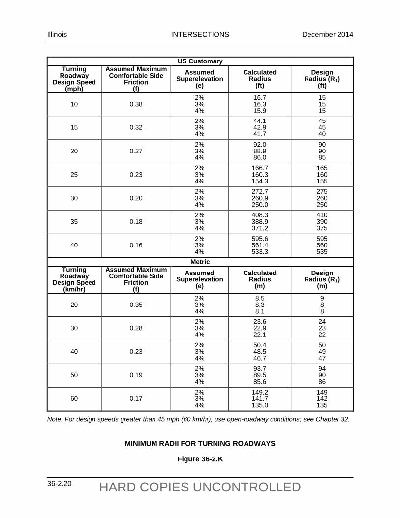
Illinois INTERSECTIONS December 2014
36-2.20 HARD COPIES UNCONTROLLED
US Customary
Turning Roadway
Design Speed (mph)
Assumed Maximum Comfortable Side
Friction (f)
Assumed Superelevation
(e)
Calculated Radius
(ft)
Design Radius (R1)
(ft)
10 0.38 2% 3% 4%
16.7 16.3 15.9
15 15 15
15 0.32 2% 3% 4%
44.1 42.9 41.7
45 45 40
20 0.27 2% 3% 4%
92.0 88.9 86.0
90 90 85
25 0.23 2% 3% 4%
166.7 160.3 154.3
165 160 155
30 0.20 2% 3% 4%
272.7 260.9 250.0
275 260 250
35 0.18 2% 3% 4%
408.3 388.9 371.2
410 390 375
40 0.16 2% 3% 4%
595.6 561.4 533.3
595 560 535
Metric Turning
Roadway Design Speed
(km/hr)
Assumed Maximum Comfortable Side
Friction (f)
Assumed Superelevation
(e)
Calculated Radius
(m)
Design Radius (R1)
(m)
20 0.35 2% 3% 4%
8.5 8.3 8.1
9 8 8
30 0.28 2% 3% 4%
23.6 22.9 22.1
24 23 22
40 0.23 2% 3% 4%
50.4 48.5 46.7
50 49 47
50 0.19 2% 3% 4%
93.7 89.5 85.6
94 90 86
60 0.17 2% 3% 4%
149.2 141.7 135.0
149 142 135
Note: For design speeds greater than 45 mph (60 km/hr), use open-roadway conditions; see Chapter 32.
MINIMUM RADII FOR TURNING ROADWAYS
Figure 36-2.K
Illinois INTERSECTIONS December 2014
36-2.21 HARD COPIES UNCONTROLLED
b. Traffic Volumes. Consider providing an acceleration lane where the turning traffic must merge with the through traffic of a high-speed, high-volume facility and/or where there is a high volume of trucks turning onto the mainline.
c. Sight Distance. Acceleration lanes may be considered if there is inadequate sight distance available to allow the driver to safely merge with the mainline facility.
d. Right-Turn vs. Left-Turn Lanes. Right-turn acceleration lanes are more common than left-turn acceleration lanes. Left-turn acceleration lanes can be considered only after an engineering study has been completed and approved by BDE.
3. Deceleration Lane Design. For guidance on the design of right-turn deceleration lanes, see Section 36-3.02.
4. Acceleration Lane Design. Consider the following when designing an acceleration lane:
a. Type. Design acceleration lanes at intersections in the same manner as for interchange ramps using the taper design; see Section 37-6.02. Under some circumstances, a parallel-lane design may be more appropriate (e.g., steep upgrade, large volume of trucks). Parallel-lane design criteria are presented in the AASHTO A Policy on Geometric Design of Highways and Streets.
b. Lengths. Right-turn acceleration lanes should meet the criteria presented in Figure 36-2.L. The “controlling curve” at an intersection is the design speed of the turning roadway or the speed at which a vehicle can make the right turn. The acceleration distance from Figure 36-2.L should be adjusted for grades using the factors presented in Figure 36-2.M. Where there is a significant number of turning trucks, the designer may consider lengthening the acceleration lane to account for their longer acceleration distances.
c. Taper. See Figure 36-2.L for the taper length distance to be provided at the end of the acceleration lane.
36-2.04 Left-Turn Control Radii
For left turns, the motorist generally has a guide at the beginning and end of the turn and an open intersection in middle. Therefore, the precise alignment of a two-centered or three-centered curve is generally not applicable. Simple curves are typically used for left-turn control radii. Occasionally, a two-centered curve may be desirable to accommodate the off-tracking of large vehicles provided the second curve has a larger radius.
The design values for left-turn control radii are usually a function of the design vehicle, angle of intersection, number of lanes, and median widths. For roadways intersecting at approximately 90°, radii of 50 ft to 80 ft (15 m to 24 m) should typically satisfy all controlling factors. If center

Illinois INTERSECTIONS December 2014
36-2.22 HARD COPIES UNCONTROLLED
Design Speed
of Highway
(mph)
Speed Reached at End of Full Lane Width (mph) (Va)
Length of Taper (ft)
L = Length of Acceleration Lane Excluding Taper (ft) For Design Speed of Turning Roadway (mph)
Stop 15 20 25 30 35 40 For Average Running Speed (mph) (V′a)
0 14 18 22 26 30 36 30 23 135 180 140
35 27 155 280 220 160
40 31 175 360 300 270 210 120
45 35 200 560 490 440 380 280 160
50 39 220 720 660 610 550 450 350 130
55 43 240 960 900 810 780 670 550 320
60 47 265 1200 1140 1100 1020 910 800 550
65 50 285 1410 1350 1310 1220 1120 1000 770
70 53 310 1620 1560 1520 1420 1350 1230 1000
Notes: 1. These values are for grades 3% or less. See Figure 36-2.M for steeper upgrades or
downgrades. 2. See Figure 36-2.K for radii of turning roadways. 3. The acceleration lengths are calculated from the distance needed for a passenger car to
accelerate from the average running speed of the entrance curve to reach a speed (Va) of approximately 5 mph below the average running speed on the mainline.
4. Length of taper approximates 3 seconds travel time at the design speed.
DESIGN LENGTHS FOR ACCELERATION LANES (Passenger Cars) (US Customary)
Figure 36-2.L

Illinois INTERSECTIONS December 2014
36-2.23 HARD COPIES UNCONTROLLED
Design Speed
of Highway (km/hr)
Speed Reached at End of Full Lane Width
(km/hr) (Va)
Length of Taper (m)
L = Length of Acceleration Lane Excluding Taper (m) For Design Speed of Turning Roadway (km/hr)
Stop 20 30 40 50 60 For Average Running Speed (km/hr) (V′a)
0 20 28 35 42 51 50 37 45 60 50 30
60 45 50 95 80 65 45
70 53 60 150 130 110 90 65
80 60 70 200 180 165 145 115 65
90 67 75 260 245 225 205 175 125
100 74 85 345 325 305 285 255 205
110 81 90 430 410 390 370 340 290
Notes: 1. These values are for grades 3% or less. See Figure 36-2.M for steeper upgrades or
downgrades. 2. See Figure 36-2.K for radii of turning roadways. 3. The acceleration lengths are calculated from the distance needed for a passenger car to
accelerate from the average running speed of the entrance curve to reach a speed (Va) of 10 km/hr below the average running speed on the mainline.
4. Length of taper approximates 3 seconds travel time at the design speed.
DESIGN LENGTHS FOR ACCELERATION LANES (Passenger Cars)
(Metric)
Figure 36-2.L
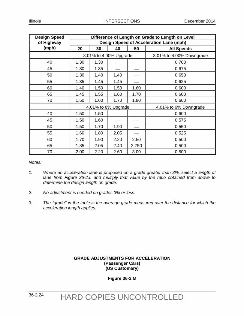
Illinois INTERSECTIONS December 2014
36-2.24 HARD COPIES UNCONTROLLED
Design Speed Difference of Length on Grade to Length on Level
of Highway Design Speed of Acceleration Lane (mph) (mph) 20 30 40 50 All Speeds
3.01% to 4.00% Upgrade 3.01% to 4.00% Downgrade 40 1.30 1.30 0.700 45 1.30 1.35 0.675 50 1.30 1.40 1.40 0.650 55 1.35 1.45 1.45 0.625 60 1.40 1.50 1.50 1.60 0.600 65 1.45 1.55 1.60 1.70 0.600 70 1.50 1.60 1.70 1.80 0.600 4.01% to 6% Upgrade 4.01% to 6% Downgrade
40 1.50 1.50 0.600 45 1.50 1.60 0.575 50 1.50 1.70 1.90 0.550 55 1.60 1.80 2.05 0.525 60 1.70 1.90 2.20 2.50 0.500 65 1.85 2.05 2.40 2.750 0.500 70 2.00 2.20 2.60 3.00 0.500
Notes: 1. Where an acceleration lane is proposed on a grade greater than 3%, select a length of
lane from Figure 36-2.L and multiply that value by the ratio obtained from above to determine the design length on grade.
2. No adjustment is needed on grades 3% or less. 3. The “grade” in the table is the average grade measured over the distance for which the
acceleration length applies.
GRADE ADJUSTMENTS FOR ACCELERATION (Passenger Cars) (US Customary)
Figure 36-2.M

Illinois INTERSECTIONS December 2014
36-2.25 HARD COPIES UNCONTROLLED
Design Speed Difference of Length on Grade to Length on Level of Highway Design Speed of Acceleration Lane (km/hr)
(km/hr) 40 50 60 70 80 All Speeds 3.01% to 4.00% Upgrade 3.01% to 4.00% Downgrade
60 1.3 1.4 1.4 0.70 70 1.3 1.4 1.4 1.5 0.65 80 1.4 1.5 1.5 1.5 1.6 0.65 90 1.4 1.5 1.5 1.5 1.6 0.60
100 1.5 1.6 1.7 1.7 1.8 0.60 110 1.5 1.6 1.7 1.7 1.8 0.60
4.01% to 6% Upgrade 4.01% to 6% Downgrade 60 1.5 1.5 0.60 70 1.5 1.6 1.7 0.60 80 1.5 1.7 1.9 1.8 0.55 90 1.6 1.8 2.0 2.1 2.2 0.55
100 1.7 1.9 2.2 2.4 2.5 0.50 110 2.0 2.2 2.6 2.8 3.0 0.50
Notes: 1. Where an acceleration lane is proposed on a grade greater than 3%, select a length of
lane from Figure 36-2.L and multiply that value by the ratio obtained from above to determine the design length on grade.
2. No adjustment is needed on grades 3% or less. 3. The “grade” in the table is the average grade measured over the distance for which the
acceleration length applies.
GRADE ADJUSTMENTS FOR ACCELERATION (Passenger Cars)
(Metric)
Figure 36-2.M

Illinois INTERSECTIONS December 2014
36-2.26 HARD COPIES UNCONTROLLED
divisional islands are present, select control radii so that the nose of each divisional island is no closer than 4 ft (1.2 m) nor greater than 10 ft (3.0 m) from the edge of the traveled way of the intersecting highway. The nose location is also affected by the selected nose radii. For additional guidance on median openings and median nose designs, see Section 36-4.04.
Left-turn control radii for dual-lane turning movements should be larger than those indicated for the single-lane design. See Section 36-3.05 for additional design details.

Illinois INTERSECTIONS October 2015
36-3.1 HARD COPIES UNCONTROLLED
36-3 AUXILIARY TURN LANES
When turning maneuvers for left- and right-turning vehicles occur from the through travel lanes, it typically disrupts the flow of through traffic. This is especially true on high-volume highways. To minimize potential conflicts and to improve the level of service and safety, the use of turn lanes may be warranted for intersections.
36-3.01 Turn Lane Guidelines
36-3.01(a) Right-Turn Lanes
The use of right-turn lanes at intersections can significantly improve operations. Consider using an exclusive right-turn lane:
• at any unsignalized intersection on a two-lane urban or rural highway that satisfies the criteria in Figure 36-3.A;
• at any unsignalized intersection on a high-speed, four-lane urban or rural highway that satisfies the criteria in Figure 36-3.B;
• on expressways at all public road intersections where the current ADT on the side road is greater than 250;
• at any intersection where a capacity analysis determines a right-turn lane is necessary to meet the level-of-service criteria;
• at any signalized intersections where the right-turning volume is greater than 150 vph and where there is greater than 300 vphpl on the mainline;
• for uniformity of intersection design along the highway if other intersections have right-turn lanes;
• at any intersection where the mainline is curved to the left and where the mainline curve requires superelevation;
• at railroad crossings where the railroad is located close to the intersection and a right-turn lane would be desirable to efficiently move through traffic on the parallel roadway; or
• at any intersection where the crash experience, existing traffic operations, sight distance restrictions (e.g., intersection beyond a crest vertical curve), or engineering judgment indicates a significant conflict related to right-turning vehicles.

Illinois INTERSECTIONS October 2015
36-3.2 HARD COPIES UNCONTROLLED
Note: For highways with a design speed below 50 mph (80 km/hr), with a DHV in one direction
of less than 300, and where right turns are greater than 40, an adjustment should be used. To read the vertical axis of the chart, subtract 20 from the actual number of right turns.
Example Given: Design Speed = 35 mph (60 km/hr) DHV (in one direction) = 250 vph Right Turns = 100 vph Problem: Determine if a right-turn lane is warranted. Solution: To read the vertical axis, use 100 - 20 = 80 vph. The figure indicates that right-
turn lane is not necessary, unless other factors (e.g., high crash rate) indicate a lane is needed.
GUIDELINES FOR RIGHT-TURN LANES AT UNSIGNALIZED INTERSECTIONS ON TWO-LANE HIGHWAYS
Figure 36-3.A

Illinois INTERSECTIONS October 2015
36-3.3 HARD COPIES UNCONTROLLED
Note: For speeds less than 50 mph (80 km/hr), see Section 36-3.01(a).
GUIDELINES FOR RIGHT-TURN LANES AT UNSIGNALIZED INTERSECTION ON FOUR-LANE HIGHWAYS
(Design Speed of 50 mph (80 km/hr) or Greater)
Figure 36-3.B

Illinois INTERSECTIONS October 2015
36-3.4 HARD COPIES UNCONTROLLED
36-3.01(b) Left-Turn Lanes
The accommodation of left turns is often the critical factor in proper intersection design. Left-turn lanes can significantly improve both the level of service and intersection safety. Always use an exclusive left-turn lane at all intersections on divided urban and rural highways with a median wide enough to accommodate a left-turn lane, regardless of traffic volumes. Consider using an exclusive left-turn lane for the following:
• at any unsignalized intersection on a two-lane urban or rural highway that satisfies the criteria in Figures 36-3.C, D, E, F, or G;
• at any signalized intersection where the left-turning volume is equal to or greater than 75 vph for a single turn lane or 300 vph for a dual turn lane;
• any intersection where a capacity analysis determines a left-turn lane is necessary to meet the level-of-service criteria, including dual left-turn lanes;
• for uniformity of intersection design along the highway if other intersections have left-turn lanes (i.e., to satisfy driver expectancy); or
• any intersection where the crash experience, traffic operations, sight distance restrictions (e.g., intersection beyond a crest vertical curve), or engineering judgment indicates a significant conflict related to left-turning vehicles.
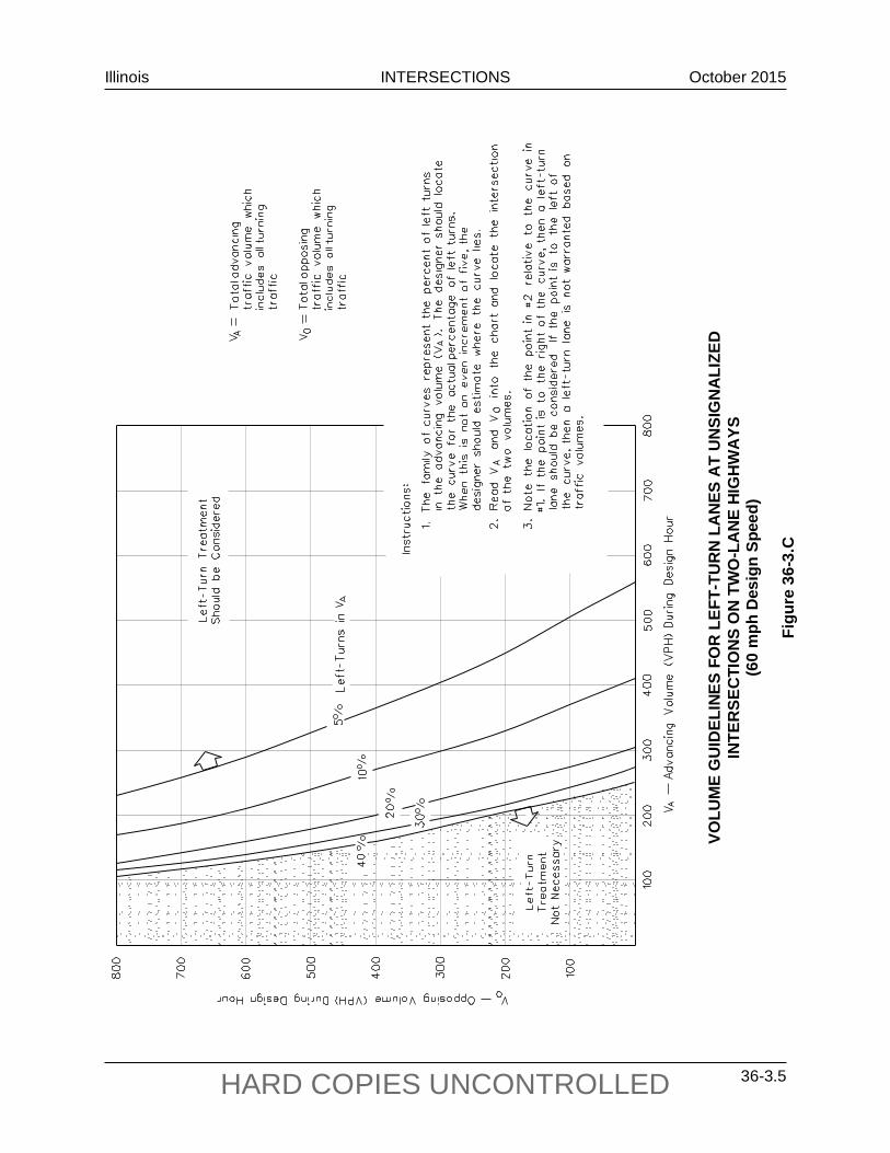
Illinois INTERSECTIONS October 2015
36-3.5 HARD COPIES UNCONTROLLED
VOLU
ME
GU
IDEL
INES
FO
R L
EFT-
TUR
N L
AN
ES A
T U
NSI
GN
ALI
ZED
INTE
RSE
CTI
ON
S O
N T
WO
-LA
NE
HIG
HW
AYS
(6
0 m
ph D
esig
n Sp
eed)
Figu
re 3
6-3.
C
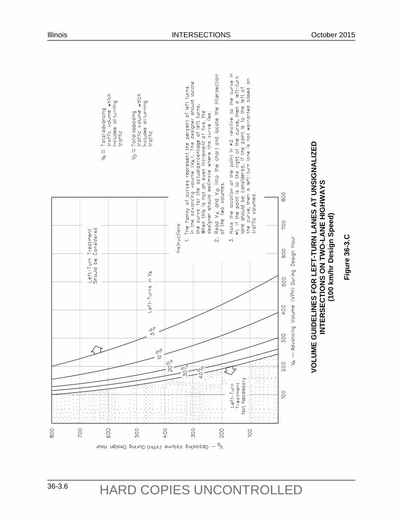
Illinois INTERSECTIONS October 2015
36-3.6 HARD COPIES UNCONTROLLED
VOLU
ME
GU
IDEL
INES
FO
R L
EFT-
TUR
N L
AN
ES A
T U
NSI
GN
ALI
ZED
INTE
RSE
CTI
ON
S O
N T
WO
-LA
NE
HIG
HW
AYS
(1
00 k
m/h
r Des
ign
Spee
d)
Figu
re 3
6-3.
C

Illinois INTERSECTIONS October 2015
36-3.7 HARD COPIES UNCONTROLLED
VOLU
ME
GU
IDEL
INES
FO
R L
EFT-
TUR
N L
AN
ES A
T U
NSI
GN
ALI
ZED
INTE
RSE
CTI
ON
S O
N T
WO
-LA
NE
HIG
HW
AYS
(5
5 m
ph D
esig
n Sp
eed)
Figu
re 3
6-3.
D

Illinois INTERSECTIONS October 2015
36-3.8 HARD COPIES UNCONTROLLED
VOLU
ME
GU
IDEL
INES
FO
R L
EFT-
TUR
N L
AN
ES A
T U
NSI
GN
ALI
ZED
INTE
RSE
CTI
ON
S O
N T
WO
-LA
NE
HIG
HW
AYS
(9
0 km
/hr D
esig
n Sp
eed)
Figu
re 3
6-3.
D
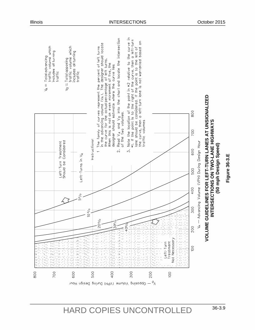
Illinois INTERSECTIONS October 2015
36-3.9 HARD COPIES UNCONTROLLED
VOLU
ME
GU
IDEL
INES
FO
R L
EFT-
TUR
N L
AN
ES A
T U
NSI
GN
ALI
ZED
INTE
RSE
CTI
ON
S O
N T
WO
-LA
NE
HIG
HW
AYS
(5
0 m
ph D
esig
n Sp
eed)
Figu
re 3
6-3.
E
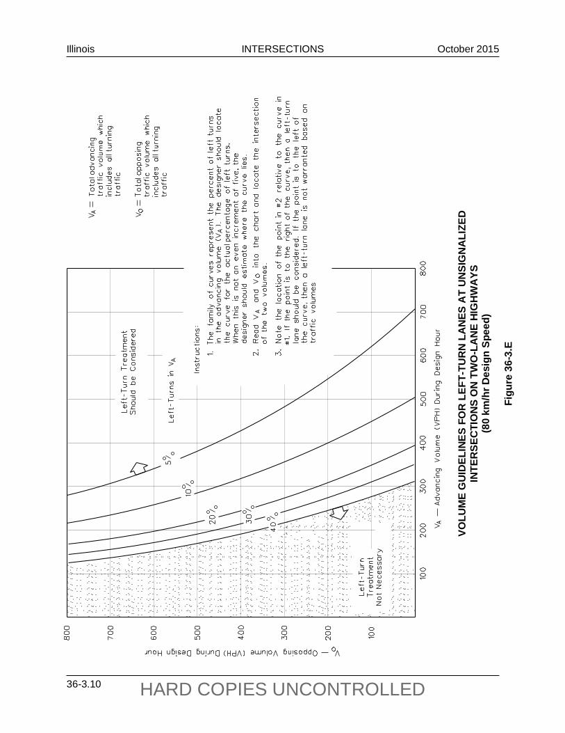
Illinois INTERSECTIONS October 2015
36-3.10 HARD COPIES UNCONTROLLED
VOLU
ME
GU
IDEL
INES
FO
R L
EFT-
TUR
N L
AN
ES A
T U
NSI
GN
ALI
ZED
INTE
RSE
CTI
ON
S O
N T
WO
-LA
NE
HIG
HW
AYS
(8
0 km
/hr D
esig
n Sp
eed)
Figu
re 3
6-3.
E

Illinois INTERSECTIONS October 2015
36-3.11 HARD COPIES UNCONTROLLED
VOLU
ME
GU
IDEL
INES
FO
R L
EFT-
TUR
N L
AN
ES A
T U
NSI
GN
ALI
ZED
INTE
RSE
CTI
ON
S O
N T
WO
-LA
NE
HIG
HW
AYS
(4
5 m
ph D
esig
n Sp
eed)
Figu
re 3
6-3.
F

Illinois INTERSECTIONS October 2015
36-3.12 HARD COPIES UNCONTROLLED
VOLU
ME
GU
IDEL
INES
FO
R L
EFT-
TUR
N L
AN
ES A
T U
NSI
GN
ALI
ZED
INTE
RSE
CTI
ON
S O
N T
WO
-LA
NE
HIG
HW
AYS
(7
0 km
/hr D
esig
n Sp
eed)
Figu
re 3
6-3.
F

Illinois INTERSECTIONS October 2015
36-3.13 HARD COPIES UNCONTROLLED
VOLU
ME
GU
IDEL
INES
FO
R L
EFT-
TUR
N L
AN
ES A
T U
NSI
GN
ALI
ZED
INTE
RSE
CTI
ON
S O
N T
WO
-LA
NE
HIG
HW
AYS
(4
0 m
ph D
esig
n Sp
eed)
Figu
re 3
6-3.
G

Illinois INTERSECTIONS October 2015
36-3.14 HARD COPIES UNCONTROLLED
VOLU
ME
GU
IDEL
INES
FO
R L
EFT-
TUR
N L
AN
ES A
T U
NSI
GN
ALI
ZED
INTE
RSE
CTI
ON
S O
N T
WO
-LA
NE
HIG
HW
AYS
(6
0 km
/hr D
esig
n Sp
eed)
Figu
re 3
6-3.
G
Illinois INTERSECTIONS October 2015
36-3.15 HARD COPIES UNCONTROLLED
36-3.02 Design of Turn Lanes
36-3.02(a) Turn Lane Widths
The width of the turn lane should be determined relative to the functional class, urban/rural location, and project scope of work (new construction, reconstruction, 3R). Part V, Design of Highway Types, of the BDE Manual presents the applicable widths for auxiliary lanes based on these criteria. Desirably, turn-lane widths should be 12 ft (3.6 m) or a minimum of 11 ft (3.3 m). The geometric design tables in Part V also provide criteria for the applicable shoulder widths adjacent to auxiliary lanes. In general, the minimum shoulder widths adjacent to a turn lane with shoulders should be 4 ft (1.2 m). For curbed sections, the minimum width of the gutter adjacent to the turn lane should be 6 in. to 24 in. (150 mm to 600 mm).
36-3.02(b) Turn Lane Lengths
Desirably, the length of a right- or left-turn lane at an intersection should allow for both safe vehicular deceleration and storage of turning vehicles outside of the through lanes. However, this is often not practical. The length of auxiliary lanes will be determined by a combination of its taper length (LT), deceleration length (LD), and storage length (LS). For urban areas, the functional length will be the taper length plus the storage length, or the deceleration length that includes the taper length, whichever is larger. For rural areas, typically the functional length will be the deceleration length that includes the taper length. In most high-speed, low-volume rural situations, the storage length will not be a controlling factor. Figure 36-3.H illustrates a schematic of auxiliary lanes at an intersection.
The following discusses IDOT criteria for turn lane lengths:
1. Taper. The entrance taper into the turn lane may be either a straight or a reverse curve taper. Always use the straight taper across bridges for ease of construction. Figure 36-3.I provides the recommended taper rates for a straight and reverse curve tapers. Where the highway is on a curved alignment, the taper of the turn lane should be more pronounced than usual to ensure that the through motorists are not inadvertently directed into the turn lane. This is accomplished by shortening the taper length. Where the entrance taper is shortened, ensure that the overall deceleration distance from Figure 36-3.I is still provided for the turn lane.
2. Deceleration. For rural facilities, the deceleration distance (LD) should meet the criteria presented in Figure 36-3.I. The following will apply:
a. Design Speed. The deceleration length will depend upon the mainline design speed and the proposed type of operation at the end of the turn lane. These design speeds are provided in the geometric design tables in Part V, Design of Highway Types.

Illinois INTERSECTIONS October 2015
36-3.16 HARD COPIES UNCONTROLLED
Not
e:
The
sche
mat
ic o
f the
maj
or ro
ad (f
ree
flow
ing)
als
o ap
plie
s to
all
legs
of a
sig
naliz
ed in
ters
ectio
n.
Key
:
L T
= Ta
per l
engt
h
L D
=
Dec
eler
atio
n le
ngth
L S
=
Sto
rage
leng
th
See
Sec
tion
36-3
.02(
b) fo
r add
ition
al g
uida
nce.
TYPI
CA
L A
UXI
LIA
RY
LAN
ES A
T A
N IN
TERS
ECTI
ON
Figu
re 3
6-3.
H
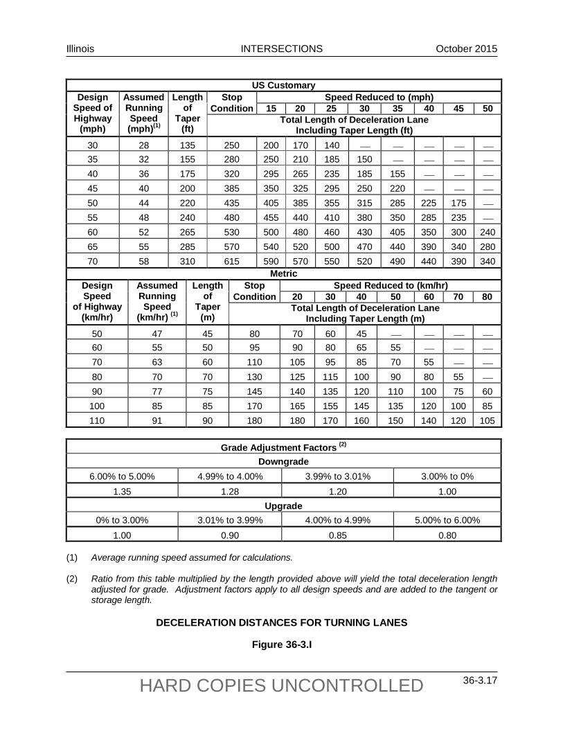
Illinois INTERSECTIONS October 2015
36-3.17 HARD COPIES UNCONTROLLED
US Customary
Design Speed of Highway
(mph)
Assumed Running Speed (mph)(1)
Length of
Taper (ft)
Stop Speed Reduced to (mph) Condition 15 20 25 30 35 40 45 50
Total Length of Deceleration Lane Including Taper Length (ft)
30 28 135 250 200 170 140 35 32 155 280 250 210 185 150 40 36 175 320 295 265 235 185 155 45 40 200 385 350 325 295 250 220 50 44 220 435 405 385 355 315 285 225 175 55 48 240 480 455 440 410 380 350 285 235 60 52 265 530 500 480 460 430 405 350 300 240 65 55 285 570 540 520 500 470 440 390 340 280 70 58 310 615 590 570 550 520 490 440 390 340
Metric Design Speed
of Highway (km/hr)
Assumed Running Speed
(km/hr) (1)
Length of
Taper (m)
Stop Speed Reduced to (km/hr) Condition 20 30 40 50 60 70 80
Total Length of Deceleration Lane Including Taper Length (m)
50 47 45 80 70 60 45 60 55 50 95 90 80 65 55 70 63 60 110 105 95 85 70 55 80 70 70 130 125 115 100 90 80 55 90 77 75 145 140 135 120 110 100 75 60
100 85 85 170 165 155 145 135 120 100 85 110 91 90 180 180 170 160 150 140 120 105
Grade Adjustment Factors (2)
Downgrade 6.00% to 5.00% 4.99% to 4.00% 3.99% to 3.01% 3.00% to 0%
1.35 1.28 1.20 1.00 Upgrade
0% to 3.00% 3.01% to 3.99% 4.00% to 4.99% 5.00% to 6.00% 1.00 0.90 0.85 0.80
(1) Average running speed assumed for calculations. (2) Ratio from this table multiplied by the length provided above will yield the total deceleration length
adjusted for grade. Adjustment factors apply to all design speeds and are added to the tangent or storage length.
DECELERATION DISTANCES FOR TURNING LANES
Figure 36-3.I

Illinois INTERSECTIONS October 2015
36-3.18 HARD COPIES UNCONTROLLED
b. Location. The deceleration distance includes the taper lengths. For left turns, the deceleration distance is usually measured beginning at the end of the left-turn control radii. For right turns, the deceleration distance may be set at either one of two locations; see Figure 36-3.H. At intersections with minor public roads (e.g., frontage roads, service drives, local roads with current ADT volumes less than 1500), a design speed of 50 mph (80 km/hr) may be used to determine the deceleration length.
c. Strategic Regional Arterials (SRA). For SRA routes, the minimum storage length should be 150 ft (45 m).
d. Grades. Where grades are greater than 3%, adjust the deceleration distance using the factors in Figure 36-3.I.
e. Urban. These distances are desirable on urban facilities; however, this is not always feasible. Under restricted urban conditions, deceleration may have to be accomplished entirely within the travel lane. For these cases, the length of full-width turn lane will be based solely on providing adequate vehicular storage (i.e., LD = 0.0 ft (0.0 m)).
f. Trucks. Where it is determined that a turn lane will be used by a large number of trucks, increase the length of the deceleration distance by approximately 30%. This will compensate for the braking constraints of large trucks.
3. Storage Length (Signalized Intersections). The storage length (LS) for turn lanes should be sufficient to store the number of vehicles likely to accumulate during the red phase of the signal cycle in the design hour. The designer should consider the following in determining the recommended storage lengths for signalized intersections:
a. Determine the distance using the criteria for signalized intersections in the Highway Capacity Manual or use the following formula:
)lanestraffic(#)hourpercycles(#
)25x2()100trucks%1()DHV()C/G1(
)ft(LengthStorage+−
= (US Customary)
)lanestraffic(#)hourpercycles(#
)5.7x2()100trucks%1()DHV()C/G1(
)m(LengthStorage+−
= (Metric)
where: G = green time (sec)
= g(protected) + g(unopposed/permitted) time values from HCM analysis (sec)
C = cycle length (sec)
DHV = Design Hourly Volume (vph) for turn lane

Illinois INTERSECTIONS October 2015
36-3.19 HARD COPIES UNCONTROLLED
b. Where right-turns-on-red are permitted or where separate right-turn signal phases are provided, the length of the right-turn lane may be reduced due to less accumulation of turning vehicles. The storage length (LS) needed for a separate right-turn lane is measured from the stop bar for the right-turning roadway; see Figure 36-3.H.
c. At signalized intersections, the designer should also consider that entry into right- and left-turn lanes may be blocked by the signal storage needs of the adjacent through lanes. If this occurs, provide longer lengths of turn lanes.
4. Storage Length (Unsignalized Intersections). To determine the minimum storage length for unsignalized intersections, assume that the intersection is signalized with a two-phase signal using a 40- second to 60-second cycle length. Then use the Highway Capacity Manual to determine the expected storage length.
5. Minimum Turn Lane Length. With safety improvement or 3R type projects, the full width length of the right- or left-turn lanes may be 115 ft (35 m) plus the taper length.
36-3.03 Left-Turn Lane Designs
36-3.03(a) General Criteria
In addition to the criteria for left-turn lane widths and lengths discussed in Section 36-3.02, the designer should consider the following general criteria:
1. Transition Areas. Do not locate left-turn lanes within any portion of a channelized approach island which is transitional in width.
2. Taper Design. Figures 36-3.H, 36-3.J, and 36-3.K illustrate the use of a straight-line taper. Figure 36-3.L illustrates the use of reverse curves for an entrance taper.
3. Offset Turn Lanes. Providing an offset design ensures that opposing left-turning motorists can see past one another to view oncoming through traffic. Offset left-turn lanes can be either a parallel or tapered type.
4. Indirect Turns. Where operational or safety concerns preclude the use of typical left-turn lanes, the designer may consider the use of indirect left turns or jughandles that cross the mainline or intersect the crossroad at a different location. Because these require special consideration and treatment, they must be developed in consultation with BDE.
5. Opposing Left-Turning Traffic. If simultaneous and opposing left-turn lanes are proposed, the designer must ensure that there is sufficient space for all turning movements. Desirably, the separation between pavement markings should be 10 ft (3 m). If space is unavailable, it will be necessary to alter the signal phasing to allow the two directions of turning traffic to move through the intersection on separate phases. See Section 36-3.05 for additional guidance.

Illinois INTERSECTIONS October 2015
36-3.20 HARD COPIES UNCONTROLLED
FLU
SH C
HA
NN
ELIZ
ED IS
LAN
DS
AT
ISO
LATE
D R
UR
AL
OR
UR
BA
N IN
TER
SEC
TIO
NS
(Saf
ety
Impr
ovem
ent o
r 3R
Pro
ject
s)
Figu
re 3
6-3.
J
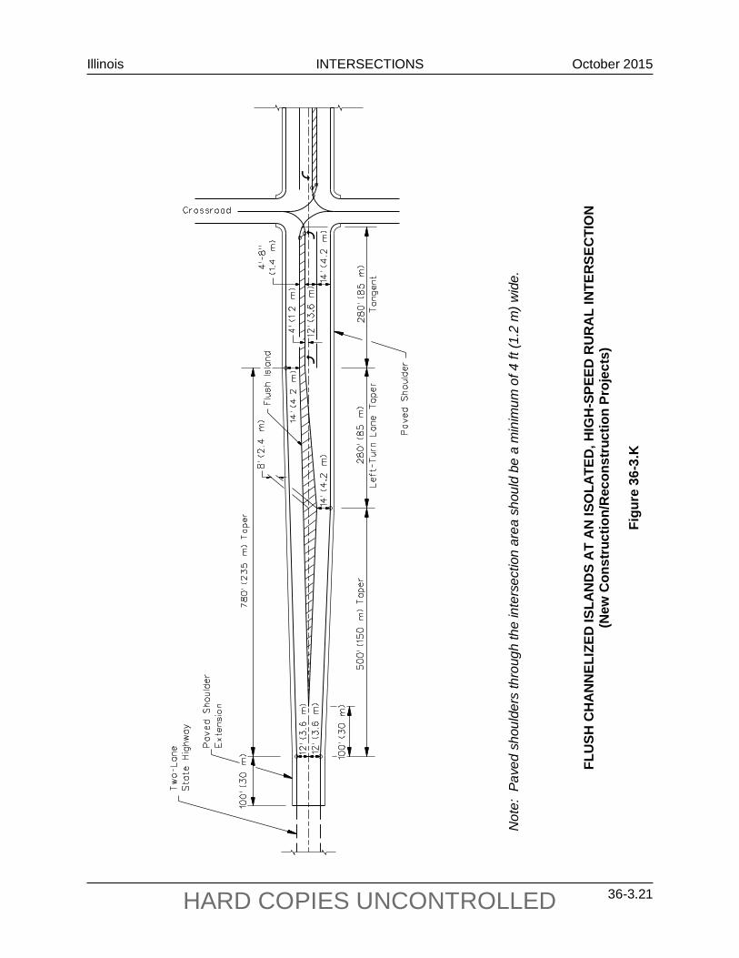
Illinois INTERSECTIONS October 2015
36-3.21 HARD COPIES UNCONTROLLED
Not
e: P
aved
sho
ulde
rs th
roug
h th
e in
ters
ectio
n ar
ea s
houl
d be
a m
inim
um o
f 4 ft
(1.2
m) w
ide.
FLU
SH C
HA
NN
ELIZ
ED IS
LAN
DS
AT
AN
ISO
LATE
D, H
IGH
-SPE
ED R
UR
AL
INTE
RSEC
TIO
N (N
ew C
onst
ruct
ion/
Rec
onst
ruct
ion
Proj
ects
)
Figu
re 3
6-3.
K
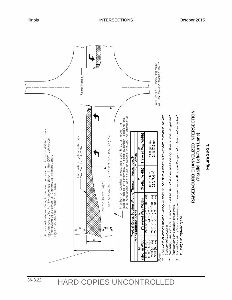
Illinois INTERSECTIONS October 2015
36-3.22 HARD COPIES UNCONTROLLED
RA
ISED
-CU
RB
CH
AN
NEL
IZED
INTE
RSE
CTI
ON
(Par
alle
l Lef
t-Tur
n La
ne)
Figu
re 3
6-3.
L
Illinois INTERSECTIONS October 2015
36-3.23 HARD COPIES UNCONTROLLED
36-3.03(b) Parallel Left-Turn Lanes Without Offset
Figures 36-3.J through 36-3.N and the following provide the design criteria for left-turn lanes that are adjacent and parallel to the through traveled way and are not offset:
1. Two-Lane Facilities. For safety improvements and 3R projects, use a flush median design at isolated intersections as shown in Figure 36-3.J. For new construction or reconstruction projects, a channelized left-turn lane with a flush island or a raised-curb island may be used depending on specific site conditions. Figure 36-3.K illustrates the flush design and Figure 36-3.L illustrates the raised-curb median design. Where the raised-curb median is channelized back to a two-lane traveled way, use the criteria discussed in the IDOT publication, Transitional Approaches to Channelized Intersections, Figure 36-3.K, and Section 36-4.03(a).
2. Narrow Raised-Curb Medians. Left-turn lanes generally will be the parallel design. This design is illustrated in Figure 36-3.L. To properly develop left-turn lanes for new construction and reconstruction projects, see the footnotes in Figure 36-3.L.
3. Narrow Expressway Medians. Left-turn lanes generally will be the parallel design due to restricted right of way. This is illustrated in Figure 36-3.M where right-of-way is restricted. Figure 36-3.M also illustrates how to terminate a median barrier before the development of the left-turn lane.
4. Multilane Highways With Wide Medians. Figure 36-3.N illustrates a typical parallel left-turn lane design with a wide depressed median. When using this design, consider the following:
• This design is generally only used where the current crossroad ADT is less than 1500 and where the current left-turn DHV in each direction from the mainline is no greater than 60 vph.
• On existing expressways or multilane facilities, median widths of 40 ft to 70 ft (12.0 m to 21.5 m) are allowed to remain in place.
• On new construction or reconstruction projects, use a median width of 50 ft (15 m) and median slopes of 1:6.

Illinois INTERSECTIONS October 2015
36-3.24 HARD COPIES UNCONTROLLED
Not
es:
1.
Use
a 2
0 ft
(6.0
m) m
edia
n on
ly w
here
RO
W o
r top
ogra
phy
dict
ates
. 2.
W
here
the
curr
ent c
ross
road
AD
T is
gre
ater
than
250
, pro
vide
righ
t-tur
n la
nes
on th
e ex
pres
sway
. 3.
A
two-
cent
ered
cur
ve is
des
irabl
e w
ith ri
ght-t
urn
lane
s; s
ee S
ectio
n 36
-2.0
1.
4.
End
the
right
-turn
dec
eler
atio
n le
ngth
at t
he b
egin
ning
of t
he ra
dius
retu
rn.
5.
Inte
rsec
tion
sigh
t dis
tanc
e m
ust b
e ch
ecke
d fo
r the
veh
icle
on
the
side
road
for t
he li
ne o
f sig
ht p
ast t
he m
edia
n ba
rrier
. 6.
Fo
r pro
per p
lace
men
t of a
sto
p si
gn, a
sm
all t
riang
ular
cor
ner i
slan
d m
ay b
e re
quire
d on
the
cros
sroa
d ap
proa
ch to
the
expr
essw
ay.
7.
See
the
Bure
au o
f Ope
ratio
n’s
Polic
y an
d Pr
oced
ures
Man
ual f
or p
rope
r pla
cem
ent o
f adv
ance
gui
de s
igns
.
EXPR
ESSW
AY
INTE
RSEC
TIO
N W
ITH
MED
IAN
BA
RR
IER
S (D
esig
n Sp
eed
≥ 50
mph
(80
km/h
r) a
nd N
arro
w M
edia
n w
ith R
estr
icte
d R
OW
)
Figu
re 3
6-3.
M

Illinois INTERSECTIONS October 2015
36-3.25 HARD COPIES UNCONTROLLED
Not
es:
1.
Whe
re th
e cu
rrent
cro
ssro
ad A
DT
is g
reat
er th
an 2
50, p
rovi
de ri
ght-t
urn
lane
s on
the
expr
essw
ay o
r m
ultil
ane
faci
lity.
2.
A
two-
cent
ered
cur
ve is
des
irabl
e w
ith ri
ght-t
urn
lane
s; s
ee S
ectio
n 36
-2.0
1.
3.
End
the
right
-turn
dec
eler
atio
n le
ngth
at t
he b
egin
ning
of t
he ra
dius
retu
rn.
4.
For
prop
er p
lace
men
t of
a s
top
sign
, a
smal
l tri
angu
lar
corn
er i
slan
d m
ay b
e re
quire
d on
the
cr
ossr
oad
appr
oach
to th
e ex
pres
sway
. 5.
Se
e th
e Bu
reau
of O
pera
tion’
s Po
licy
and
Proc
edur
es M
anua
l for
pro
per p
lace
men
t of a
dvan
ce g
uide
si
gns.
Se
e Se
ctio
n 36
-3.0
3(b)
for a
dditi
onal
des
ign
deta
ils.
EXPR
ESSW
AY
OR
MU
LTIL
ANE
FA
CIL
ITY
WIT
H A
WID
E M
EDIA
N ≥
40
ft (1
2 m
) (P
aral
lel L
eft-T
urn
Lane
Des
ign
With
out O
ffset
)
Figu
re 3
6-3.
N
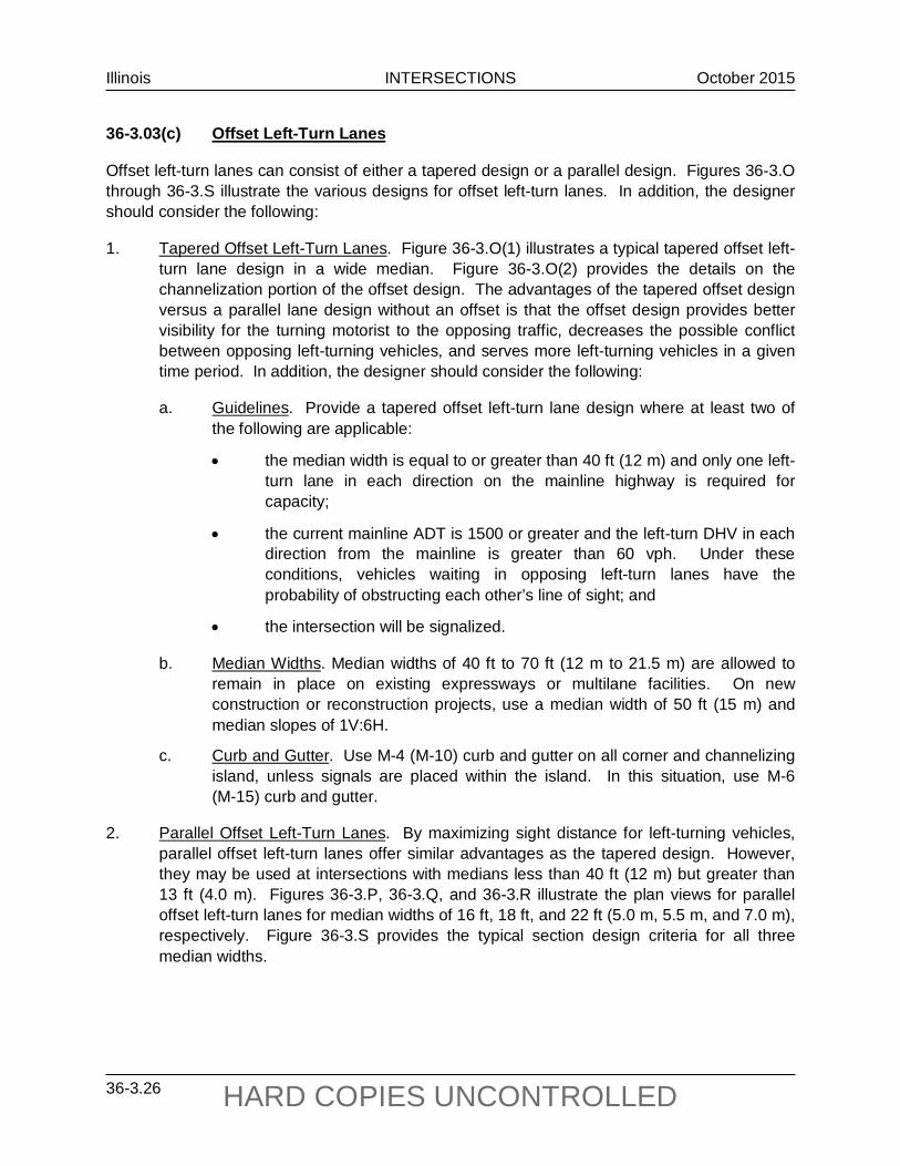
Illinois INTERSECTIONS October 2015
36-3.26 HARD COPIES UNCONTROLLED
36-3.03(c) Offset Left-Turn Lanes
Offset left-turn lanes can consist of either a tapered design or a parallel design. Figures 36-3.O through 36-3.S illustrate the various designs for offset left-turn lanes. In addition, the designer should consider the following:
1. Tapered Offset Left-Turn Lanes. Figure 36-3.O(1) illustrates a typical tapered offset left-turn lane design in a wide median. Figure 36-3.O(2) provides the details on the channelization portion of the offset design. The advantages of the tapered offset design versus a parallel lane design without an offset is that the offset design provides better visibility for the turning motorist to the opposing traffic, decreases the possible conflict between opposing left-turning vehicles, and serves more left-turning vehicles in a given time period. In addition, the designer should consider the following:
a. Guidelines. Provide a tapered offset left-turn lane design where at least two of the following are applicable:
• the median width is equal to or greater than 40 ft (12 m) and only one left-turn lane in each direction on the mainline highway is required for capacity;
• the current mainline ADT is 1500 or greater and the left-turn DHV in each direction from the mainline is greater than 60 vph. Under these conditions, vehicles waiting in opposing left-turn lanes have the probability of obstructing each other’s line of sight; and
• the intersection will be signalized.
b. Median Widths. Median widths of 40 ft to 70 ft (12 m to 21.5 m) are allowed to remain in place on existing expressways or multilane facilities. On new construction or reconstruction projects, use a median width of 50 ft (15 m) and median slopes of 1V:6H.
c. Curb and Gutter. Use M-4 (M-10) curb and gutter on all corner and channelizing island, unless signals are placed within the island. In this situation, use M-6 (M-15) curb and gutter.
2. Parallel Offset Left-Turn Lanes. By maximizing sight distance for left-turning vehicles, parallel offset left-turn lanes offer similar advantages as the tapered design. However, they may be used at intersections with medians less than 40 ft (12 m) but greater than 13 ft (4.0 m). Figures 36-3.P, 36-3.Q, and 36-3.R illustrate the plan views for parallel offset left-turn lanes for median widths of 16 ft, 18 ft, and 22 ft (5.0 m, 5.5 m, and 7.0 m), respectively. Figure 36-3.S provides the typical section design criteria for all three median widths.

Illinois INTERSECTIONS October 2015
36-3.27 HARD COPIES UNCONTROLLED
Not
es:
1.
Pla
ce d
rain
age
inle
ts in
the
M-4
.24
(M-1
0.60
) gut
ter t
o fa
cilit
ate
drai
nage
with
in th
e le
ft-tu
rn b
ay.
2.
A tw
o-ce
nter
ed c
urve
is d
esira
ble
with
righ
t-tur
n la
nes;
see
Sec
tion
36-2
.01.
3.
Whe
re a
lef
t-tur
n la
ne i
s re
quire
d, d
esig
n th
e m
edia
n as
a r
aise
d-cu
rb m
edia
n fo
r de
linea
tion.
W
here
no
med
ian
is p
ropo
sed,
the
m
inim
um tr
avel
ed w
ay w
idth
sho
uld
be 2
2 ft
(6.6
m).
4.
End
the
right
-turn
dec
eler
atio
n le
ngth
at b
egin
ning
of t
he ra
dius
turn
.
5.
See
the
Bur
eau
of O
pera
tion’
s P
olic
y an
d Pr
oced
ures
Man
ual f
or p
rope
r pla
cem
ent o
f gui
de s
ign.
Con
side
r pro
vidi
ng li
ghtin
g at
this
inte
rsec
tion.
EXPR
ESSW
AY
OR
MU
LTIL
ANE
FA
CIL
ITY
WIT
H M
EDIA
N W
IDTH
≥ 4
0 ft
(12
m)
(Tap
ered
Offs
et L
eft-T
urn
Lane
Des
ign)
)
Figu
re 3
6-3.
O(1
)

Illinois INTERSECTIONS October 2015
36-3.28 HARD COPIES UNCONTROLLED
TYPICAL CORNER ISLAND AND CHANNELIZATION DETAILS (Tapered Offset Left-Turn Lane)
Figure 36-3.O(2)

Illinois INTERSECTIONS October 2015
36-3.29 HARD COPIES UNCONTROLLED
Note: See Figure 36-3.S for typical Section A-A.
TYPICAL DESIGN FOR PARALLEL OFFSET LEFT-TURN LANES (Existing 16 ft (4.88 m) Wide Traversable Median)
Figure 36-3.P

Illinois INTERSECTIONS October 2015
36-3.30 HARD COPIES UNCONTROLLED
Note: See Figure 36-3.S for typical Section A-A.
TYPICAL DESIGN FOR PARALLEL OFFSET LEFT-TURN LANES (18 ft (5.5 m) Raised-Curb Median)
Figure 36-3.Q

Illinois INTERSECTIONS October 2015
36-3.31 HARD COPIES UNCONTROLLED
Note: See Figure 36-3.S for typical Section A-A.
TYPICAL DESIGN FOR PARALLEL OFFSET LEFT-TURN LANES (22 ft (7.0 m) Raised-Curb Median)
Figure 36-3.R

Illinois INTERSECTIONS October 2015
36-3.32 HARD COPIES UNCONTROLLED
Not
e: S
ee F
igur
es 3
6-3.
P, 3
6-3.
Q, a
nd 3
6-3.
R fo
r loc
atio
n of
Sec
tion
A-A
.
TYPI
CA
L SE
CTI
ON
WIT
H P
AR
ALL
EL O
FFSE
T LE
FT-T
UR
N L
AN
ES
Figu
re 3
6-3.
S
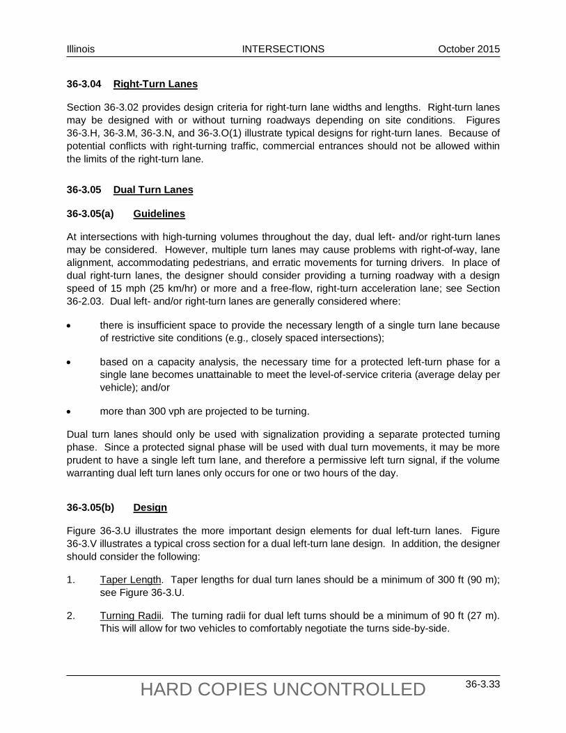
Illinois INTERSECTIONS October 2015
36-3.33 HARD COPIES UNCONTROLLED
36-3.04 Right-Turn Lanes
Section 36-3.02 provides design criteria for right-turn lane widths and lengths. Right-turn lanes may be designed with or without turning roadways depending on site conditions. Figures 36-3.H, 36-3.M, 36-3.N, and 36-3.O(1) illustrate typical designs for right-turn lanes. Because of potential conflicts with right-turning traffic, commercial entrances should not be allowed within the limits of the right-turn lane.
36-3.05 Dual Turn Lanes
36-3.05(a) Guidelines
At intersections with high-turning volumes throughout the day, dual left- and/or right-turn lanes may be considered. However, multiple turn lanes may cause problems with right-of-way, lane alignment, accommodating pedestrians, and erratic movements for turning drivers. In place of dual right-turn lanes, the designer should consider providing a turning roadway with a design speed of 15 mph (25 km/hr) or more and a free-flow, right-turn acceleration lane; see Section 36-2.03. Dual left- and/or right-turn lanes are generally considered where:
• there is insufficient space to provide the necessary length of a single turn lane because of restrictive site conditions (e.g., closely spaced intersections);
• based on a capacity analysis, the necessary time for a protected left-turn phase for a single lane becomes unattainable to meet the level-of-service criteria (average delay per vehicle); and/or
• more than 300 vph are projected to be turning.
Dual turn lanes should only be used with signalization providing a separate protected turning phase. Since a protected signal phase will be used with dual turn movements, it may be more prudent to have a single left turn lane, and therefore a permissive left turn signal, if the volume warranting dual left turn lanes only occurs for one or two hours of the day.
36-3.05(b) Design
Figure 36-3.U illustrates the more important design elements for dual left-turn lanes. Figure 36-3.V illustrates a typical cross section for a dual left-turn lane design. In addition, the designer should consider the following:
1. Taper Length. Taper lengths for dual turn lanes should be a minimum of 300 ft (90 m); see Figure 36-3.U.
2. Turning Radii. The turning radii for dual left turns should be a minimum of 90 ft (27 m). This will allow for two vehicles to comfortably negotiate the turns side-by-side.

Illinois INTERSECTIONS October 2015
36-3.34 HARD COPIES UNCONTROLLED
3. Throat Width. Because the presence of center and corner islands may restrict the turning paths, the design width at the edges of the left-turning paths may be critical. Also, the magnitude of the inner radius influences the amount of off-tracking and, as such, the required width of the turning path. Figure 36-3.T gives the minimum widths of two-lane, left-turn departure openings based on the dimension of the inner radius and on the design of the traveled way edges at the most critical location of off-tracking.
Two-Lane Left-Turn Facilities
Inner Radius Traveled Way Edge Design
Minimum Width of Departure Opening
90 ft to 160 ft (27 m to 49 m)
Shoulder and Shoulder Curb and Shoulder
Curb and Curb
35 ft (10.5 m) E-E 35 ft (10.5 m) + GW 35 ft (10.5 m) + GWs
160 ft to 250 ft (50 m to 75 m)
Shoulder and Shoulder Curb and Shoulder
Curb and Curb
33 ft (9.8 m) E-E 33 ft (9.8 m) + GW 33 ft (9.8 m) + GWs
GW = Gutter Width E-E = Edge to Edge
MINIMUM DEPARTURE OPENINGS FOR DUAL LEFT-TURN LANES
Figure 36-3.T
4. Median Widths and Type. Dual left-turn lanes require a minimum median width of 30 ft
(9.0 m). For access management, the median shall be barrier curb, where the design speed is less than 50 mph. If the design speed is 50 mph or greater, consult with the Bureau of Design & Environment for guidance. The median approaching the left turn lanes should fully shadow the dual left turn lanes. If the median width approaching (upstream) the intersection is less than 30 feet, 30 foot minimum median width and barrier type curb should extend, at a minimum, throughout the length of the left turn bay taper and storage up to the stop bar.
5. Special Pavement Markings. Consult with the District Bureau of Traffic or the Bureau of Operations in the Central Office for the use of pavement marking within the intersection to effectively and safely guide two lines of vehicles turning abreast
6. Opposing Left-Turning Traffic. If opposing dual left-turn lanes are proposed, the designer must ensure that there is sufficient space for all turning movements. Desirably, the separation between the outside edges of the opposing left turn turning paths should be 10 ft (3 m); see Figure 36-3.U. If space is unavailable, it will be necessary to alter the signal phasing to allow the two directions of turning traffic to move through the intersection on separate phases.

Illinois INTERSECTIONS October 2015
36-3.35 HARD COPIES UNCONTROLLED
SCH
EMA
TIC
FO
R D
UA
L LE
FT-T
UR
N L
AN
ES
(Rai
sed-
Cur
b M
edia
n)
Figu
re 3
6-3.
U

Illinois INTERSECTIONS October 2015
36-3.36 HARD COPIES UNCONTROLLED
7. Turning Templates. The turning paths for multiple turn lanes must be checked for conflicts by using the applicable turning templates or a computer simulated turning template program. The designer should assume that the selected design vehicle will turn from the outside lane of the multiple turn lanes. Desirably, the inside vehicle should be an SU but, as a minimum, the inside vehicle can be assumed to be a passenger car turning side by side with the selected design vehicle. Include a printout of the computer simulated turning paths with the IDS, if applicable.

Illinois INTERSECTIONS October 2015
36-3.37 HARD COPIES UNCONTROLLED
Note: See Figure 36-3.U for location of Section A-A.
TYPICAL SECTION WITH DUAL LEFT-TURN LANES (Raised-Curb Median and Posted Speed < 50 mph (80 km/hr))
Figure 36-3.V
Illinois INTERSECTIONS October 2015
36-4.1 HARD COPIES UNCONTROLLED
36-4 CHANNELIZING ISLANDS
Several of the treatments described in this chapter require channelizing islands within the intersection area. Some intersections, especially those with oblique angle crossings, result in large paved areas that may cause motorists to wander from natural or expected paths and may cause long pedestrian crossings. These movements may result in conflicts and/or unpredictable operations, but could be enhanced by incorporating channelizing islands in the design of the intersection.
At rural locations where higher speeds are prevalent, channelizing islands are used in conjunction with left-turn lanes and for turning roadways. In urban areas where speeds generally are lower, but where traffic volumes are generally higher, channelizing islands in conjunction with added lanes are used primarily to increase capacity and safety at the intersection.
36-4.01 Island Types
Islands can be grouped into the following classifications. Most island types serve at least two of these functions:
1. Corner/Directional Islands. Directional or corner triangular islands control and direct right-turn movements and guide the driver into the proper direction. Section 36-2.02 discusses corner islands.
2. Channelizing Islands. Center channelizing islands separate opposing traffic flows, alert the driver to the crossroad ahead, and regulate traffic through an intersection. These islands are often introduced at intersections on undivided highways and are particularly advantageous in controlling left turns at skewed intersections.
3. Refuge Islands. Refuge islands (corner islands or center channelizing islands) may function to aid and protect pedestrians who cross a wide roadway. These islands may be required for pedestrians where complex signal phasing is used and may permit the use of two-stage crossings. This also may increase the signal efficiency by allowing the time allocated for pedestrian movements to be reduced.
36-4.02 Selection of Island Type
Islands may be some combination of flush, traversable, raised-curb, or turf, and could be triangular or elongated in shape. Selection of an appropriate type of channelizing island should be based on:
• traffic characteristics; • cost considerations; • urban, suburban, or rural locations;

Illinois INTERSECTIONS October 2015
36-4.2 HARD COPIES UNCONTROLLED
• degree of access management desired; and • maintenance considerations.
The following offers guidance where different types of islands are appropriate.
36-4.02(a) Flush or Traversable Islands
Flush islands, which are delineated by pavement markings (e.g., paint, thermoplastic, epoxy), or traversable islands, which are delineated by M-2 (M-5) curbs, are appropriate:
• on highways to delineate separate left-turn lanes (flush or traversable);
• in restricted locations where delineation of vehicular path is desirable, but space for larger, raised-curb islands is not available (flush);
• in areas where better long-term visual delineation is needed at night and during inclement weather, but space for raised-curb islands is not available (traversable);
• to separate opposing traffic streams on low-speed urban streets (flush or traversable); and/or
• for temporary channelization during construction (flush).
36-4.02(b) Raised-Curb Islands
Raised-curb islands are at least 4 in. (100 mm) high and are appropriate:
• on low-speed highways where the primary function is to provide positive separation for opposing traffic movements;
• at locations requiring positive delineation of vehicular paths, such as where a major route turns or at intersections with unusual geometry;
• where the island is intended to prohibit or prevent traffic movements (e.g., wrong-way movements or to manage access within the intersection);
• where a primary or secondary island function is to provide a location for traffic signals, signs, or other fixed objects; and/or
• where a primary function of the island is to provide a pedestrian refuge.
Raised-curb islands should be used at rural intersections having the following characteristics:
• on the crossroad through an interchange to delineate median crossovers and turn lanes, and to prevent wrong-way movements, and

Illinois INTERSECTIONS October 2015
36-4.3 HARD COPIES UNCONTROLLED
• at unusual or complex intersection configurations where higher visibility would promote greater safety and more efficient traffic operations.
Where curb and gutter is proposed in high-speed rural areas, only use mountable curbs and consider providing supplemental intersection illumination. In addition, provide prismatic reflectors on the top of curbs to enhance delineation of the island and turn lanes at night. Section 34-2.04 provides further guidance on the types of curbing used for islands.
36-4.02(c) Pavement Edge Islands
Channelizing islands formed by pavement edges generally only apply to rural or suburban areas. One example of this channelization type is where a divided four-lane facility with a median ditch section is temporarily tapered to a two-lane highway section. This reduction of the four lanes down to two is considered channelization. See Chapter 45 for details of these channelized approaches.
36-4.03 Design of Islands
36-4.03(a) Channelizing Islands
Because center channelizing islands (flush or raised-curb) are often introduced within the traveled way, special care is necessary to their design to ensure that they do not become a hazard. The designer should consider the following criteria:
1. Nose. Place the noses of raised-curb islands so that they are conspicuous to approaching motorists and are outside of the assumed vehicular path. This clearance should be both physical and visual so that drivers will not veer away from the island.
2. Nose Ramping. Ramp the approach nose of raised-curb according to the criteria presented in the IDOT Highway Standards. Nose ramping is applicable where:
• a raised-curb median or curbed centerline channelization is introduced to separate opposing lanes of traffic;
• a change is made from a flush or traversable two-way, left-turn lane to a raised-curb median; and
• median crossovers or openings are outlined with curb and gutter.
At locations that are designed for the protection of pedestrians, traffic signals, light standards, or sign supports, nose ramping may be considered optional.
3. Alignment. Provide a smooth, free-flowing alignment both into and out of the divided roadway. On entering the channelized approach, widen the traveled way out opposite the curbed nose and gradually transition it to the normal divided traveled way width. Also, provide a gradual transition on the departure side of the divided roadway. Where two lanes are being funneled down to one lane on the departure side of the channelizing
Illinois INTERSECTIONS October 2015
36-4.4 HARD COPIES UNCONTROLLED
island, provide sufficient pavement width and/or an outside paved shoulder at the curbed nose to provide some lateral escape clearance for merging vehicles. This is important where a motorist has failed to observe the single lane warning signs and is still operating two abreast as the vehicle approaches the transition to two-lane, two-way operations.
4. Island Size. Traffic channelizing islands should be large enough to command the driver’s attention. Island shapes and sizes vary from one intersection to another. The minimum width for a flush-type island on new construction is 13 ft (4.0 m) and for 3R construction is 12 ft (3.6 m). For raised-curb islands introduced at isolated intersections, the divisional island should be designed according to the IDOT publication Transitional Approaches to Channelized Intersections and Figure 36-3.L. Also, see Figure 36-4.A. For flush, channelizing islands introduced at isolated intersections, see Figures 36-3.J and 36-3.K.
5. Island Length. The island should be of sufficient length to forewarn a motorist of an approaching intersection and to provide space for the proper development of a free-flowing alignment. The edge of the traveled way, the width of the divided roadways, and the width of the center channelizing island normally control the length of island and the pavement edge radii.
6. Delineation. Channelizing islands should be delineated based on their size, location, and function. Raised-curb islands present the most positive means of delineation. Where space is limited, use paint to delineate the island. Raised pavement markers, curb-top reflectors, or paint striping can be used in advance of and around an island to help alert the driver of an approaching island. These traffic control devices are especially important at the approach to raised-curb divisional islands.
Round the approach and merging ends of curbed islands according to Figure 36-4.A.
7. Offsets. Figure 36-4.A provides guidance on the applicable offsets that should be used with curbed-channelizing islands.
8. Corrugated Median Surface. In advance of the curbed nose of a divisional island, provide a sufficient length of corrugated median that allows the driver enough warning time to move away from the raised-curb island. Use 1½ seconds of travel time based on the design speed to determine the length of the corrugated surface.
9. Cross Slopes. With center curbed-channelizing islands, up to approximately 32 ft (9.5 m) wide and where such islands are located on tangent segments or on very flat curvature, the length of the island normally provides sufficient distance for gradual lateral shifts of traffic either to the right (entering) or to the left (departing). Because the required lateral shifts usually are not greater than the normal rate of lane shifts made during a passing measure, the cross slope of the pavement through the channelized approach can be unidirectional at 3/16″/ft (1.5%) or 1/4″/ft (2%) and should be sloped away from the island.

Illinois INTERSECTIONS October 2015
36-4.5 HARD COPIES UNCONTROLLED
Not
es:
1.
For
addi
tiona
l de
sign
det
ails
, se
e th
e ID
OT
publ
icat
ion
Tran
sitio
nal A
ppro
ache
s to
Cha
nnel
ized
Inte
rsec
tions
. 2.
Th
e le
ngth
and
sha
pe o
f ch
anne
lizin
g is
land
s de
rived
from
th
e ab
ove
sket
ch
also
m
ay
be
used
as
a
guid
e fo
r de
term
inin
g a
flush
, cen
ter i
slan
d de
sign
. 3.
If
W2 =
14
ft (4
.2 m
), us
e a
3/16″/
ft (1
.5%
) dra
inag
e sl
ope
on
the
trave
led
way
. 4.
If
W2
= 22
ft
(6.6
m)
or 2
4 ft
(7.2
m),
use
a 1/
4″/ft
(2.
0%)
drai
nage
slo
pe o
n th
e tra
vele
d w
ay.
TYPI
CA
L C
HA
NN
ELIZ
ING
ISLA
ND
DES
IGN
(Rai
sed-
Cur
b M
edia
ns)
Figu
re 3
6-4.
A

Illinois INTERSECTIONS October 2015
36-4.6 HARD COPIES UNCONTROLLED
10. Stopping Sight Distance. At a minimum, provide stopping sight distance to the ramped
nose of the island. Desirably, provide decision sight distance to the ramped nose.
11. Typical Designs. Figure 36-4.A illustrates a typical curbed divisional island and applicable approach treatment. Guidance for standardized designs based on various design speeds, pavement widths, and island widths are provided in IDOT’s Transitional Approaches to Channelized Intersections. This document can be found on the IDOT website under Consultant Resources. For flush-channelizing islands, see Figures 36-3.J and 36-3.K.
12. Simplicity. Do not introduce divisional islands in areas which can create confusion due to complexity or which cause excessive restrictions. Complex intersections, which present multiple choices of movement, are undesirable. Ensure that the design remains simple to eliminate possible confusion.
36-4.03(b) Corner Islands
See Sections 36-2.02 and 36-2.03 for design details on corner islands.
36-4.03(c) Curb Ramps
See Section 58-1 for the application of ADA criteria at intersections. If the crosswalk is placed through an island, give special consideration to the treatment of curb ramps within the raised-curb island. In many cases, the crosswalk can be located directly in front of a divisional island nose without special design provisions or the island can be shortened sufficiently to permit such location without loss of control for turning vehicles. However, where an island does encroach on the location of a crosswalk, it is usually desirable to depress the entire crosswalk through the island, rather than construct ramps. This is particularly true if the island is less than 100 ft2 (10 m2) or is less than 16 ft (4.8 m) wide. The remaining portion of raised island on either side of the ramp should be of sufficient size to distinguish it as a raised island and for ease of construction.
36-4.04 Median Openings
36-4.04(a) Location/Spacing
Desirably, median openings should be provided on divided highways at all public roads and major traffic generators. However, this may result in close intersection spacing that may impair the operation of the facility. The following recommended minimum spacings should be evaluated when determining the location for a median opening:
1. Rural Facilities. Median openings should be at least ½ mile (800 m) apart and, desirably, 1 mile (1.6 km) apart, subject to public service requirements and as determined by an engineering study.

Illinois INTERSECTIONS October 2015
36-4.7 HARD COPIES UNCONTROLLED
2. Urban Facilities. The desirable minimum spacing between median openings should be approximately ¼ mile (400 m). However, this may not always be practical. At a minimum, the spacing of median openings should be far enough apart to allow for the development of exclusive left-turn lanes with proper lengths.
For both rural and urban facilities, the available sight distance in the vicinity of a median opening is also a factor in the determination of its location. In addition, on some facilities, commercial establishments with heavy truck traffic may dictate the location of median openings. For additional details on the location and spacing of median openings, see Chapters 45 through 48.
36-4.04(b) Design
Figure 36-4.B presents a general figure for the design of a median opening at an intersection. The following will apply to the design of median openings:
1. Design Vehicle. Use the largest vehicle that will be making a left turn with some frequency. See Section 36-1.08 for guidelines in selecting the design vehicle.
2. Encroachment. The desirable design will allow the design vehicle to make a left turn and to remain entirely within the through inside lane of the divided facility. In addition, the turning vehicle should be no closer than 2 ft (600 mm) to the inside curb or inside edge of pavement. However, depending on traffic control or available intersection sight distance, it would be acceptable for the design vehicle to occupy both travel lanes; see Figure 36-4.B.
3. Length of Opening. The length of a median opening should properly accommodate the turning path of the design vehicle. The minimum length is the largest of the following:
• approach width plus 8 ft (2.4 m), including crossroad median width; • approach width plus the width of shoulders, including crossroad median width; • the length based on the selected design vehicle; or • 40 ft (12 m).
Evaluate each median opening individually to determine the proper length. Consider the following factors in the evaluation:
a. Turning Templates. Check the proposed design with the turning template for the selected design vehicle. Give consideration to the frequency of the turn and to the encroachment onto adjacent travel lanes or shoulders by the turning vehicle.
b. Nose Offset. At four-leg intersections, traffic traveling through the median opening (going straight) will pass the nose of the median end (semicircular or bullet nose). To provide a sense of comfort for these drivers, the offset between the crossroad through travel lane (extended) and the median nose should be at least 4 ft (1.2 m).

Illinois INTERSECTIONS October 2015
36-4.8 HARD COPIES UNCONTROLLED
Not
e: S
ee d
iscu
ssio
n in
Sec
tion
36-4
.04(
b) fo
r min
imum
L c
riter
ia.
MED
IAN
OPE
NIN
G D
ESIG
N
Figu
re 3
6-4.
B
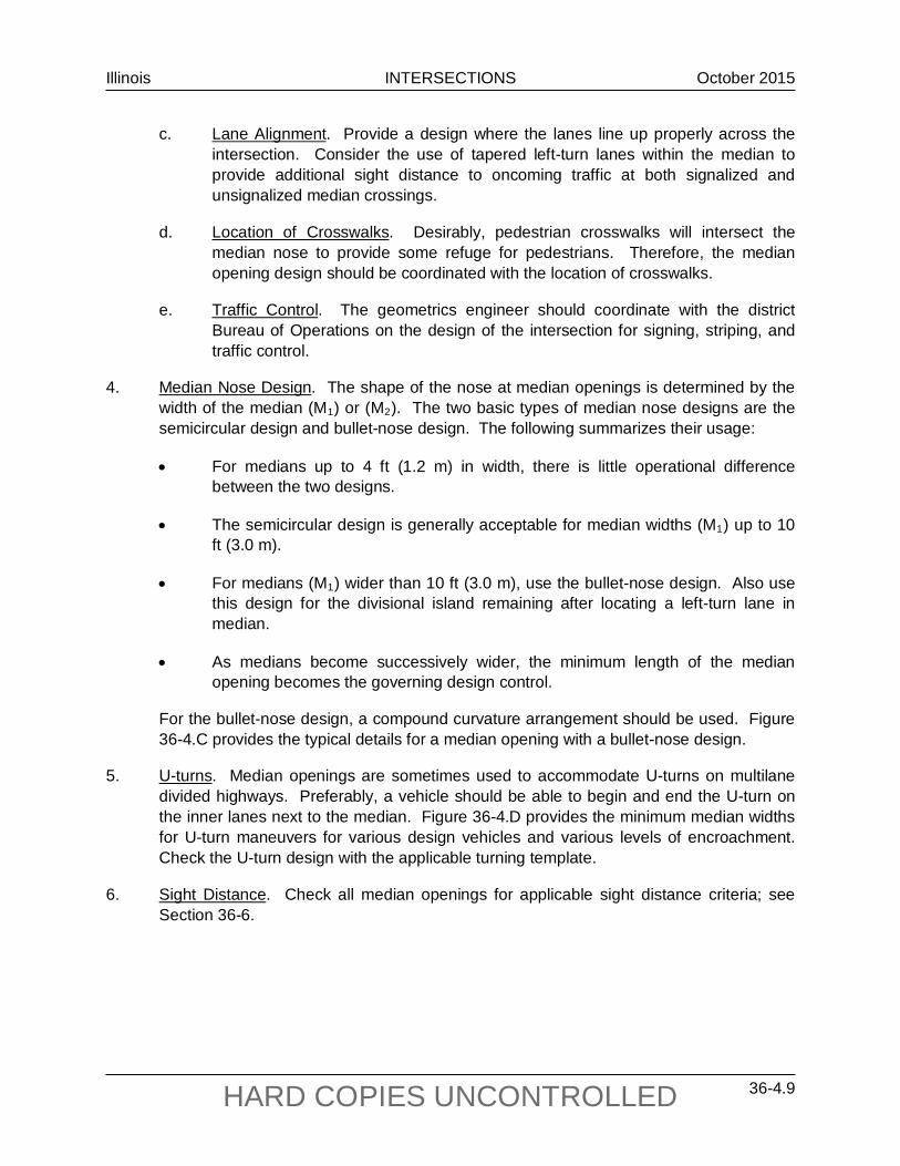
Illinois INTERSECTIONS October 2015
36-4.9 HARD COPIES UNCONTROLLED
c. Lane Alignment. Provide a design where the lanes line up properly across the intersection. Consider the use of tapered left-turn lanes within the median to provide additional sight distance to oncoming traffic at both signalized and unsignalized median crossings.
d. Location of Crosswalks. Desirably, pedestrian crosswalks will intersect the median nose to provide some refuge for pedestrians. Therefore, the median opening design should be coordinated with the location of crosswalks.
e. Traffic Control. The geometrics engineer should coordinate with the district Bureau of Operations on the design of the intersection for signing, striping, and traffic control.
4. Median Nose Design. The shape of the nose at median openings is determined by the width of the median (M1) or (M2). The two basic types of median nose designs are the semicircular design and bullet-nose design. The following summarizes their usage:
• For medians up to 4 ft (1.2 m) in width, there is little operational difference between the two designs.
• The semicircular design is generally acceptable for median widths (M1) up to 10 ft (3.0 m).
• For medians (M1) wider than 10 ft (3.0 m), use the bullet-nose design. Also use this design for the divisional island remaining after locating a left-turn lane in median.
• As medians become successively wider, the minimum length of the median opening becomes the governing design control.
For the bullet-nose design, a compound curvature arrangement should be used. Figure 36-4.C provides the typical details for a median opening with a bullet-nose design.
5. U-turns. Median openings are sometimes used to accommodate U-turns on multilane divided highways. Preferably, a vehicle should be able to begin and end the U-turn on the inner lanes next to the median. Figure 36-4.D provides the minimum median widths for U-turn maneuvers for various design vehicles and various levels of encroachment. Check the U-turn design with the applicable turning template.
6. Sight Distance. Check all median openings for applicable sight distance criteria; see Section 36-6.
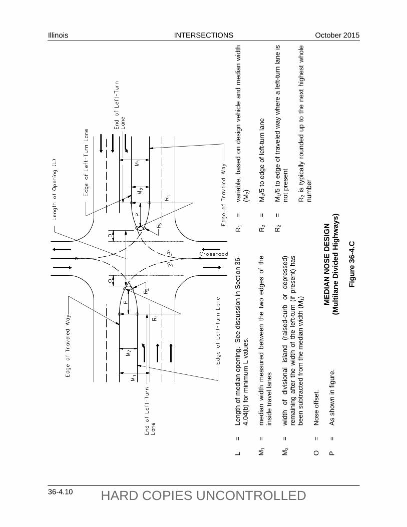
Illinois INTERSECTIONS October 2015
36-4.10 HARD COPIES UNCONTROLLED
MED
IAN
NO
SE D
ESIG
N (M
ultil
ane
Divi
ded
Hig
hway
s)
Figu
re 3
6-4.
C
L =
Leng
th o
f med
ian
open
ing.
See
dis
cuss
ion
in S
ectio
n 36
-4.
04(b
) for
min
imum
L v
alue
s.
M1
= m
edia
n w
idth
mea
sure
d be
twee
n th
e tw
o ed
ges
of t
he
insi
de tr
avel
lane
s M
2 =
wid
th
of
divi
sion
al
isla
nd
(rai
sed-
curb
or
de
pres
sed)
re
mai
ning
afte
r th
e w
idth
of
the
left-
turn
(if
pres
ent)
has
been
sub
tract
ed fr
om th
e m
edia
n w
idth
(M1)
O
=
Nos
e of
fset
. P
=
As
show
n in
figu
re.
R1
= va
riabl
e, b
ased
on
desi
gn v
ehic
le a
nd m
edia
n w
idth
(M
2)
R2
= M
2/5 to
edg
e of
left-
turn
lane
R
2 =
M1/5
to e
dge
of tr
avel
ed w
ay w
here
a le
ft-tu
rn la
ne is
no
t pre
sent
R
2 is
typ
ical
ly r
ound
ed u
p to
the
nex
t hi
ghes
t w
hole
nu
mbe
r

Illinois INTERSECTIONS October 2015
36-4.11 HARD COPIES UNCONTROLLED
M - Min. width of median for design vehicle
Type of Maneuver P SU BUS WB-40 (WB-12)
WB-50 (WB-15)
Length of design vehicle
19 ft (5.7 m)
30 ft (9.0 m)
40 ft (12.0 m)
50 ft (15.0 m)
55 ft (16.5 m)
Inner Lane to
Inner Lane
30 ft (9 m)
63 ft (19 m)
63 ft 19 m)
61 ft (18 m)
71 ft (21 m)
Inner Lane to
Outer Lane
18 ft (5 m)
51 ft (15 m)
51 ft (15 m)
49 ft (15 m)
59 ft (18 m)
Inner Lane to
Shoulder
8 ft (2 m)
41 ft (12 m)
41 ft (12 m)
39 ft (12 m)
49 ft (15 m)
MINIMUM WIDTHS NEEDED FOR U-TURNS (Multilane Divided Highways)
Figure 36-4.D

Illinois INTERSECTIONS October 2015
36-4.12 HARD COPIES UNCONTROLLED
Illinois INTERSECTIONS October 2015
36-5.1 HARD COPIES UNCONTROLLED
36-5 EXTENSION OF THROUGH LANES BEYOND AN INTERSECTION
Where traffic volumes drop off considerably after passing a crossroad, one lane can be dropped beyond the intersection. A lane may be dropped downstream as an exclusive turn lane or with a merging taper into the adjacent through lane. In either scenario, proper highway signing and pavement striping is critical in order to convey the upstream lane drop to the motorist.
To fully realize capacity benefits and to provide for a safe merge when utilizing a merging taper, the through lanes must be extended beyond the intersection for a defined minimum distance. Figure 36-5.A provides preliminary design criteria for determining the minimum distance a lane should be extended beyond an intersection. For higher volume locations, additional length beyond the minimum may be required for the formation of adequate gaps in traffic that will minimize conflicts during merging. Each intersection should therefore be designed on a case-by-case basis, considering all site specific factors.

Illinois INTERSECTIONS October 2015
36-5.2 HARD COPIES UNCONTROLLED
EXTE
NSIO
N O
F TH
RO
UGH
LA
NE
BEYO
ND
AN
INTE
RSE
CTI
ON
Figu
re 3
6-5.
A
Not
es:
1.
DE is
that
dis
tanc
e re
quire
d by
a v
ehic
le to
acc
eler
ate
from
a
stop
to
5 m
ph (
10 k
m/h
r) be
low
the
des
ign
spee
d of
the
hi
ghw
ay.
2.
The
tape
r di
stan
ce i
s ca
lcul
ated
ass
umin
g a
12 f
t (3
.6 m
) la
ne a
nd a
tape
r rat
e of
45:
1 fo
r des
ign
spee
ds o
f 45
mph
(70
km/h
r) o
r les
s or
50:
1 fo
r des
ign
spee
ds o
f 50
mph
(80
km/h
r) or
gre
ater
.
Illinois INTERSECTIONS September 2010
36-6.1 HARD COPIES UNCONTROLLED
36-6 INTERSECTION SIGHT DISTANCE
36-6.01 General
At each intersection the potential exists for vehicles to conflict with each other when entering, exiting, or crossing the intersection. The designer should provide sufficient sight distance for a driver to perceive these potential conflicts and to perform the necessary actions needed to negotiate the intersection safely. The additional costs and impacts to achieve this sight distance are often justified based on the safety and operational considerations.
Because all intersections on State highways are either stop controlled or signalized, no guidelines are provided for no control or yield-controlled intersections. For these types of intersections, the designer is referred to NCHRP Report 383, Intersection Sight Distance for guidance and/or the AASHTO Policy on the Geometric Design of Highways and Streets.
36-6.02 Design Procedures
The Department uses gap acceptance as the conceptual basis for its intersection sight distance (ISD) criteria. The ISD criteria used by the Department is intended to find a balance between an acceptable level of safety and what can be provided at an intersection on a practical basis. This ISD methodology ensures than an intersection operates smoothly without forcing a vehicle on the major road to stop. As the crossroad vehicle makes the turn and accelerates, field studies have indicated that mainline vehicles reduce their speed to approximately 70% of the mainline design speed to compensate for the entering vehicle.
The intersection sight distance is obtained by providing clear sight triangles both to the right and left as shown in Figure 36-6.A. The lengths of legs of these sight triangles are determined as follows:
1. Minor Road. The length of leg along the minor road is based on two parts. The first is the location of the driver’s eye on the minor road. This is typically assumed to be 14.4 ft (4.4 m) from the edge of the major road traveled way. The second part is based on the distance to the center of the vehicle on the major road. For right-turning vehicles, this is assumed to be the center of the closest travel lane from the left. For left-turning vehicles, this is assumed to be the center of the closest travel lane for vehicles approaching from the right.
2. Major Road. The length of the sight triangle or ISD along the major road is determined using the following equation:
b = ISD = 1.467 Vmajor tc (US Customary) Equation 36-6.1 b = ISD = 0.278 Vmajor tc (Metric) Equation 36-6.1
where: b = length of sight triangle along the major road or ISD, ft (m) ISD = Intersection Sight Distance, ft (m) Vmajor = design speed of major road, mph (km/hr) tc = critical gap for entering or crossing the major road, sec

Illinois INTERSECTIONS September 2010
36-6.2 HARD COPIES UNCONTROLLED
CLEAR SIGHT TRIANGLES FOR STOP-CONTROLLED INTERSECTIONS
Figure 36-6.A

Illinois INTERSECTIONS September 2010
36-6.3 HARD COPIES UNCONTROLLED
The critical gap time (tc) varies according to the design vehicle, the grade on the minor road approach, the number of lanes on the major roadway, the type of operation, and the intersection skew.
Within this clear sight triangle, if practical, remove or lower any object that would obstruct the driver’s view. These objects may include buildings, parked or turning vehicles, trees, hedges, tall crops, unmowed grass, fences, retaining walls, and the actual ground line. In addition, where an interchange ramp or crossroad intersects the major road near a bridge on a crest vertical curve, items such as bridge parapets, piers, abutments, guardrail, or the crest vertical curve itself may restrict the clear sight triangle. Figure 36-6.B illustrates, in both the plan view and profile view, the application of the clear sight triangles at an interchange ramp. This figure also applies to any crossroad intersection.
The height of eye for passenger cars is assumed to be 3.5 ft (1080 mm) above the surface of the minor road. The height of object for an approaching vehicle on the major road is also assumed to be 3.5 ft (1080 mm). An object height of 3.5 ft (1080 mm) assumes that a sufficient portion (9 in (225 mm)) of an oncoming passenger car must be seen to identify it as an object of concern by the minor road driver. Using the 3.5 ft (1080 mm) height for both vehicles assumes that each driver can see and recognize the other vehicle. If there are a sufficient number of trucks on the minor road or ramp to warrant their consideration, use Figure 36-6.C to determine the appropriate eye height for the minor road vehicle.
36-6.03 Stop-Controlled Intersections
Where traffic on the minor road or an exit ramp of an intersection is controlled by stop signs, the driver of the vehicle on the minor road must have adequate sight distance for a safe departure from the stopped position. This assumes that the approaching vehicle comes into view just as the stopped vehicle begins it departure. The following sections discuss the application of the Department’s ISD methodology at stop-controlled intersections.
36-6.03(a) Turns Onto Major Roadway
To determine the intersection sight distance for vehicles turning left or right onto the major road, the designer should use Equation 36-6.1 and the gap times (tc) presented in Figure 36-6.D. Figure 36-6.D also presents adjustments to the gap times for multilane facilities and steep grades on the minor road approach. These adjustments are further discussed below. Figure 36-6.E provides the ISD values for typical design vehicles on two-lane, level facilities. The designer should also consider the following:
1. Turning Maneuver. There is only a minimal difference in the base gap acceptance times between the left- and right-turning drivers. Consequently, only one gap time is provided for both the left- and right-turning vehicle onto the major road. See Figure 36-6.B.

Illinois INTERSECTIONS September 2010
36-6.4 HARD COPIES UNCONTROLLED
IS
D –
in
ters
ectio
n si
ght d
ista
nce,
ft (m
) d
– m
inim
um d
ista
nce
need
ed fr
om b
ack
of
para
pet e
xten
sion
or s
ide
of s
truct
ure
to
vehi
cle
posi
tion,
ft (m
)
do
– w
hen
min
or ro
ad is
ove
r
du
– w
hen
min
or ro
ad is
und
er
A
– m
axim
um a
lgeb
raic
diff
eren
ce o
f gra
des
(%)
L –
Leng
th o
f cre
st v
ertic
al c
urve
, ft (
m)
W
– w
idth
of l
ane,
ft (m
) h 1
–
heig
ht o
f eye
, see
Fig
ure
36-6
.C
h 2
– he
ight
of o
bsta
cle
= 3.
5 ft
(108
0mm
) (p
asse
nger
car
ass
umed
)
INTE
RSE
CTI
ON
SIG
HT
DIST
AN
CE
CON
TRO
LS
Figu
re 3
6-6.
B
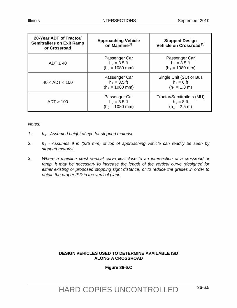
Illinois INTERSECTIONS September 2010
36-6.5 HARD COPIES UNCONTROLLED
20-Year ADT of Tractor/ Semitrailers on Exit Ramp
or Crossroad Approaching Vehicle
on Mainline(2) Stopped Design
Vehicle on Crossroad (1)
ADT ≤ 40 Passenger Car
h2 = 3.5 ft (h2 = 1080 mm)
Passenger Car h2 = 3.5 ft
(h1 = 1080 mm)
40 < ADT ≤ 100 Passenger Car
h2 = 3.5 ft (h2 = 1080 mm)
Single Unit (SU) or Bus h1 = 6 ft
(h1 = 1.8 m)
ADT > 100 Passenger Car
h2 = 3.5 ft (h2 = 1080 mm)
Tractor/Semitrailers (MU) h1 = 8 ft
(h1 = 2.5 m)
Notes:
1. h1 - Assumed height of eye for stopped motorist.
2. h2 - Assumes 9 in (225 mm) of top of approaching vehicle can readily be seen by stopped motorist.
3. Where a mainline crest vertical curve lies close to an intersection of a crossroad or ramp, it may be necessary to increase the length of the vertical curve (designed for either existing or proposed stopping sight distance) or to reduce the grades in order to obtain the proper ISD in the vertical plane.
DESIGN VEHICLES USED TO DETERMINE AVAILABLE ISD ALONG A CROSSROAD
Figure 36-6.C

Illinois INTERSECTIONS September 2010
36-6.6 HARD COPIES UNCONTROLLED
Design Vehicle Gap Acceptance Time (tc) (sec)
Passenger Car 7.5
Single-Unit Truck 9.5
Tractor/Semitrailer 11.5
Note: Times are for turns onto a two-lane highway without a median and may require
adjustments to the base time gaps. Adjustments: 1. Multilane Highways. The following will apply:
• For left turns onto two-way multilane highways without a median, add 0.5 seconds for passenger cars or 0.7 seconds for trucks for each additional lane from the left, in excess of one, to be crossed by the turning vehicle. See discussion in Section 36-6.03(a) for additional guidance.
• For right turns, no adjustment is necessary.
2. Minor Road Approach Grades. If the approach grade on the minor road exceeds +3%, the
following will apply:
• For right turns, multiply 0.1 seconds times the actual percent grade on the minor road approach and add this number to the base time gap.
• For left turns, multiple 0.2 seconds times the actual percent grade on the minor
approach and add this number to the base time gap. 3. Major Road Approach Grade. Major road grade does not affect calculations.
GAP ACCEPTANCE TIMES (Left and Right Turns From Minor Road)
Figure 36-6.D

Illinois INTERSECTIONS September 2010
36-6.7 HARD COPIES UNCONTROLLED
Design Speed (Vmajor)
ISD
Passenger Cars Single-Unit Trucks Tractor/Semitrailers
US Customary
20 mph 225 ft 280 ft 340 ft
25 mph 280 ft 350 ft 425 ft
30 mph 335 ft 420 ft 510 ft
35 mph 390 ft 490 ft 595 ft
40 mph 445 ft 560 ft 675 ft
45 mph 500 ft 630 ft 760 ft
50 mph 555 ft 700 ft 845 ft
55 mph 610 ft 770 ft 930 ft
60 mph 665 ft 840 ft 1015 ft
65 mph 720 ft 910 ft 1100 ft
70 mph 775 ft 980 ft 1185 ft
Metric
30 km/hr 63 m 80 m 96 m
40 km/hr 84 m 106 m 128 m
50 km/hr 105 m 132 m 160 m
60 km/hr 126 m 159 m 192 m
70 km/hr 146 m 185 m 224 m
80 km/hr 167 m 212 m 256 m
90 km/hr 188 m 238 m 288 m
100 km/hr 209 m 264 m 320 m
110 km/hr 230 m 291 m 352 m Notes: 1. These ISD values assume turns onto a two-lane facility without a median. 2. These ISD values assume a minor road approach grade ≤ +3%.
INTERSECTION SIGHT DISTANCES FOR TWO-LANE HIGHWAY (Left and Right Turns From Minor Road)
Figure 36-6.E

Illinois INTERSECTIONS September 2010
36-6.8 HARD COPIES UNCONTROLLED
2. Multilane Facilities. For multilane facilities, the gap acceptance times presented in Figure 36-6.D may need to be adjusted to account for the additional distance required by the turning vehicle to cross the additional lanes or median. The following will apply:
a. Left-Turns. For left turns onto multilane highways without a median, add 0.5 seconds for passenger cars or 0.7 seconds for trucks for each additional lane from the left, in excess of one, to be crossed by the turning vehicle. Assume that the left-turning driver will enter the left most travel lane on the far side of the major road.
b. Right Turns. Because the turning vehicle is assumed to be turning into the nearest right through lane, no adjustments to the gap times are required. This is the same for either two-lane or multilane facilities.
c. Medians. Depending on the median width, it also may be necessary to add additional time to the base gap time; see Item 3.
3. Left Turns Through Medians.
a. Narrow Medians. For a facility that does not have a median wide enough to store a stopped design vehicle, divide the median width by 12 ft (3.6 m) to get the corresponding number of lanes and then use the criteria in Item 2a above to determine the additional time factor.
b. Wide Medians. For a facility that does have a median wide enough to store a stopped design vehicle, the designer should evaluate the sight distance needed in two separate steps:
• First, with the design vehicle stopped on the side road, use the gap acceptance times for a vehicle turning right or use Figure 36-6.E directly to determine the applicable ISD. Under some circumstances, it may also be necessary to check the straight through crossing maneuver to determine if it is the critical movement. Straight through crossing criteria are discussed in Section 36-6.03(b).
• Second, with the design vehicle stopped in the median, assume a two-lane roadway design and use the gap acceptance times for a vehicle turning left or use Figure 36-6.E directly to determine the applicable ISD.
Section 36-6.07 provides an example of school bus crossing a wide median.
4. Approach Grades. If the approach grade on the minor road exceeds 3%, see the criteria in Figure 36-6.D.
5. Trucks. At some intersections (e.g., near truck stops, interchange ramps, grain elevators), the designer may want to use the truck as the design vehicle for determining the ISD. The gap acceptance times (tc) for single-unit and tractor/semitrailer trucks are provided in Figure 36-6.D. Calculated ISD values for two-lane roadways are presented

Illinois INTERSECTIONS September 2010
36-6.9 HARD COPIES UNCONTROLLED
in Figure 36-6.E. The height of eye for these vehicles is discussed in Section 36-6.02 as shown in Figure 36-6.C.
36-6.03(b) Vehicle Crossing Mainline
In the majority of cases, the intersection sight distance for a crossing maneuver is less than that required for a left- or right-turning vehicle. However, in the following situations, the straight through crossing sight distance may be the more critical movement:
• where left and/or right turns are not permitted from a particular approach and the crossing maneuver is the only legal or expected movement (e.g., indirect left turns);
• where the design vehicle must cross more than four travel lanes or, with medians, the equivalent distance; or
• where a substantial volume of heavy vehicles cross the highway and there are steep grades on the minor road approaches.
Use Equation 36-6.1 and the gap acceptance times (tc) and adjustment factors in Figure 36-6.F to determine the ISD for crossing maneuvers. Where narrow medians are present which cannot store the design vehicle, include the median width in the overall width to determine the applicable gap time. Divide this overall width by 12 ft (3.6 m) to determine the corresponding number of lanes for the crossing maneuver. Add 0.5 seconds for passenger cars or 0.7 seconds for trucks for each additional lane, in excess of two, to be crossed by the design vehicle.
Design Vehicle Gap Acceptance Time (tc) (sec) Passenger Car 6.5
Single-Unit Truck 8.5 Tractor/Semitrailer 10.5
Note: Times are for crossing a two-lane highway without a median. Adjustments: 1. Multilane Highway. Where the design vehicle is crossing a major road with more than two lanes
and/or where there is a narrow median which cannot store the design vehicle, add 0.5 seconds for passenger cars or 0.7 seconds for trucks for each additional lane in excess of two. See the discussion in Section 36-6.03(b) for additional guidance.
2. Approach Grade. If the approach grade on the minor road exceeds +3%, multiply 0.1 seconds times
the actual percent grade of the minor road approach, and add this number to the base time gap.
GAP ACCEPTANCE TIMES (Vehicle Crossing Mainline)
Figure 36-6.F

Illinois INTERSECTIONS September 2010
36-6.10 HARD COPIES UNCONTROLLED
36-6.03(c) Four-Way Stop
At intersections with all-way stop control, provide enough sight distance so that the first stopped vehicle on each approach is visible to all the other approaches. The ISD criteria for left- or right-turning vehicles as discussed in Section 36-6.03(a) are not applicable in this situation. Often intersections are converted to all-way stop control to address limited sight distance at the intersection. Therefore, providing additional sight distance at the intersection is unnecessary.
36-6.04 Signal-Controlled Intersections
At signalized intersections, provide sufficient sight distance so that the first vehicle on each approach is visible to all other approaches. Traffic signals are often used at high-volume intersections to address accidents related to restricted sight distances. Therefore, the ISD criteria for left- or right-turning vehicles as discussed in Section 36-6.03(a) is typically not applicable at signalized intersections. However, where right-turn-on-red is allowed, check to see that the ISD as presented in Section 36-6.03(a) for a stop-controlled right-turning vehicle is available to the left. If it is not, this may warrant restricting the right-turn-on-red movement. In addition, if the traffic signal is placed on two-way flash operation (i.e., flashing amber on the major-road approaches and flashing red on the minor-road approaches) under off-peak or nighttime conditions, provide the ISD criteria as discussed in Section 36-6.03(a) for a stop-controlled intersection.
36-6.05 Left Turns From the Major Road
At all intersections, regardless of the type of traffic control, the designer should consider the sight distance needs for a stopped vehicle turning left from the major road. This situation is illustrated in Figure 36-6.G. The driver will need to see straight ahead for a sufficient distance to turn left and clear the opposing travel lanes before an approaching vehicle reaches the intersection. In general, if the major highway has been designed to meet the stopping sight distance criteria, intersection sight distance only will be a concern where the major road is on a horizontal curve, where there is a median, or where there are opposing vehicles making left turns at an intersection. Sight distance for opposing left turns may be increased by offsetting the left-turn lanes; see Section 36-3.03(c).
Use Equation 36-6.1 and the gap acceptance times (tc) from Figure 36-6.H to determine the applicable intersection sight distances for the left-turning vehicle. Where the left-turning vehicle must cross more than one opposing lane, add 0.5 seconds for passenger cars or 0.7 seconds for trucks for each additional lane in excess of one. Where medians are present and the left-turn lanes are not offset, the designer will need to consider the median width in the same manner as discussed in Section 36-6.03. Figure 36-6.I provides the ISD values for typical design vehicles and two common left-turning situations on a facility without a median.

Illinois INTERSECTIONS September 2010
36-6.11 HARD COPIES UNCONTROLLED
INTE
RSE
CTI
ON
S SI
GH
T D
ISTA
NCE
CO
NTR
OLS
(L
eft T
urns
from
the
Maj
or R
oad)
Figu
re 3
6-6.
H
INTE
RSE
CTI
ON
S SI
GH
T D
ISTA
NCE
CO
NTR
OLS
(L
eft T
urns
from
the
Maj
or R
oad)
Figu
re 3
6-6.
G
Not
e: S
ee S
ectio
n 36
-6.0
5 fo
r dis
cuss
ion
and
appl
icat
ion

Illinois INTERSECTIONS September 2010
36-6.12 HARD COPIES UNCONTROLLED
Design Vehicle Gap Acceptance Time (tc) (sec)
Passenger Car 5.5
Single-Unit Truck 6.5
Tractor/Semitrailer 7.5
Adjustments: Where left-turning vehicles cross more than one opposing lane, add 0.5 seconds for
passenger cars or 0.7 seconds for trucks for each additional lane in excess of one. See Section 36-6.05 for additional guidance on median widths.
GAP ACCEPTANCE TIMES (Left Turns From Major Road)
Figure 36-6.I
36-6.06 Effect of Skew
Where is it is impractical to realign an intersection which is greater than 30° from perpendicular, adjust the gap acceptance times presented in the above sections to account for the additional travel time required for a vehicle to make a turn or cross a facility. At oblique-angled intersections, determine the actual path length for a turning or crossing vehicle by dividing the total distance of the lanes and/or median to be crossed by the sine of the intersection angle. If the actual path length exceeds the total width of the lanes to be crossed by 12 ft (3.6 m) or more, apply the applicable adjustment factors; see Figure 36-6.J.

Illinois INTERSECTIONS September 2010
36-6.13 HARD COPIES UNCONTROLLED
Design Speed (Vmajor)
ISD Passenger Cars Single-Unit Trucks Tractor/Semitrailers
Crossing 1 lane
Crossing 2 lanes
Crossing 1 lane
Crossing 2 lanes
Crossing 1 lane
Crossing 2 lanes
US Customary 20 mph 165 ft 180 ft 195 ft 210 ft 225 ft 240 ft
25 mph 205 ft 225 ft 240 ft 260 ft 280 ft 295 ft
30 mph 245 ft 265 ft 290 ft 310 ft 335 ft 355 ft
35 mph 285 ft 310 ft 335 ft 365 ft 390 ft 415 ft
40 mph 325 ft 355 ft 385 ft 415 ft 445 ft 475 ft
45 mph 365 ft 400 ft 430 ft 465 ft 500 ft 530 ft
50 mph 405 ft 445 ft 480 ft 515 ft 555 ft 590 ft
55 mph 445 ft 490 ft 525 ft 570 ft 610 ft 650 ft
60 mph 490 ft 530 ft 575 ft 620 ft 665 ft 710 ft
65 mph 530 ft 575 ft 625 ft 670 ft 720 ft 765 ft
70 mph 570 ft 620 ft 670 ft 720 ft 775 ft 825 ft Metric
30 km/hr 50 m 50 m 55 m 59 m 63 m 67 m
40 km/hr 65 m 67 m 73 m 78 m 84 m 89 m
50 km/hr 77 m 84 m 91 m 98 m 105 m 112 m
60 km/hr 92 m 100 m 109 m 117 m 125 m 134 m
70 km/hr 107 m 117 m 127 m 137 m 146 m 156 m
80 km/hr 123 m 134 m 145 m 156 m 167 m 178 m
90 km/hr 138 m 150 m 163 m 175 m 188 m 200 m
100 km/hr 153 m 167 m 181 m 195 m 209 m 223 m
110 km/hr 169 m 184 m 199 m 214 m 230 m 245 m Note: Assumes no median on major road.
INTERSECTION SIGHT DISTANCES (Left Turns From Major Road)
Figure 36-6.J
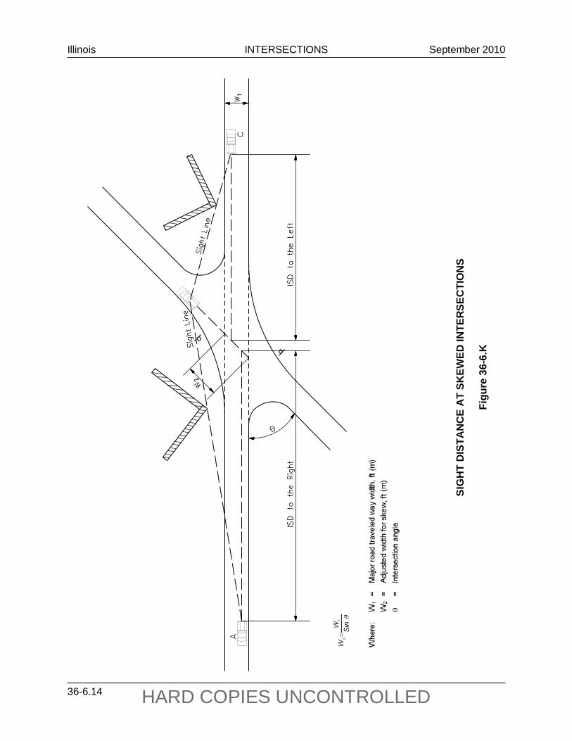
Illinois INTERSECTIONS September 2010
36-6.14 HARD COPIES UNCONTROLLED
SIG
HT
DIS
TAN
CE
AT
SKEW
ED IN
TERS
ECTI
ON
S
Figu
re 3
6-6.
L
SIG
HT
DIS
TAN
CE
AT
SKEW
ED IN
TERS
ECTI
ON
S
Figu
re 3
6-6.
K

Illinois INTERSECTIONS September 2010
36-6.15 HARD COPIES UNCONTROLLED
36-6.07 Examples of ISD Applications
The following three examples illustrate the application of the ISD criteria:
Example 36-6.07(1)
Given: Minor road intersects a four-lane highway with a TWLTL. Minor road is stop controlled and intersects major road at 90°. Design speed of the major highway is 45 mph. All travel lane widths are 12 ft.
The TWLTL width is 12 ft. Grade on minor road is 1%.
Trucks are not a concern.
Problem: Determine the intersection sight distance needed to the left and right of the minor road; see Figure 36-6.B.
Solution:
1. For the passenger car turning right, the ISD to the left can be determined directly from Figure 36-6.E, because the right-turning motorist is assumed to turn into the near lane. For the 45 mph design speed, the ISD to the left is 500 ft.
2. For the passenger car turning left, the ISD to the right must reflect the additional time required to cross the additional lanes and TWLTL; see in Section 36-6.03(a). The following will apply:
a. First, determine the extra width required by the one additional travel lane and the TWLTL and divide this number by 12 ft:
lanes212
)1212(=
+
b. Next, multiply the number of lanes by 0.5 seconds to determine the additional
time required:
(2 lanes)(0.5 sec/lane) = 1.0 second
c. Add the additional time to the basic gap time of 7.5 seconds and insert this value into Equation 36-6.1:
ISD = (1.467)(45)(7.5 + 1.0) = 561 ft
Provide an ISD of 561 ft to the right for the left-turning vehicle.
3. Check the passenger vehicle crossing the mainline, as discussed in Section 36-6.03(b). The following will apply:

Illinois INTERSECTIONS September 2010
36-6.16 HARD COPIES UNCONTROLLED
a. First determine the extra width required by the two additional travel lanes and the TWLTL and divide this number by 12 ft:
lanes0.312
)121212(=
++
b. Next, multiply the number of lanes by 0.5 seconds to determine the additional time required:
(3.0 lanes)(0.5 sec/lane) = 1.5 seconds
c. Add the additional time to the basic gap time of 6.5 seconds and insert this value into Equation 36-6.1:
ISD = (1.467)(45)(6.5 + 1.5) = 530 ft
The 530 ft for the crossing maneuver is less than the 561 ft required for the left-turning vehicle and, therefore, is not the critical maneuver.
4. Prepare a scaled drawing in the horizontal and vertical planes and graphically check to determine if the applicable ISD is available.
Example 36-6.07(2)
Given: Minor road intersects a four-lane divided highway. Minor road is stop controlled and intersects major road at 90°. Design speed of the major highway is 60 mph. All travel lane widths are 12 ft.
The median width is 50 ft. Grade on minor road is +2%.
The design vehicle is a 64-passenger school bus that is 35.8 ft long.
Problem: Determine the intersection sight distance needed to the left and right of the minor road; see Figure 36-6.B.
Solution:
1. For a school bus, assume a SU design vehicle for gap acceptance times.
2. For the school bus turning right, the ISD to the left can be determined directly from Figure 36-6.E. For the 60 mph design speed, the ISD to the left is 840 ft.
3. Determine if the straight through crossing maneuver is critical; see Section 36-6.03(b). No adjustments are required to the base time of 8.5 seconds. Therefore, use Equation 36-6.1 directly:
ISD = (1.467)(60)(8.5) = 750 ft

Illinois INTERSECTIONS September 2010
36-6.17 HARD COPIES UNCONTROLLED
The crossing maneuver ISD is less than the right-turning maneuver and, therefore, is not critical.
4. For the school bus turning left, it can be assumed the school bus can safely stop in the median (i.e., 50 ft minus 35.8 ft). The ISD to the right can be determined directly from Figure 36-6.E. For the 60 mph design speed, the ISD to the right for the left turn is 840 ft. The crossing maneuver will not be critical.
5. Prepare a scaled drawing in the horizontal and vertical planes and graphically check to determine if the applicable ISD is available.
Example 36-6.07(3)
Given: Minor road intersects a four-lane divided highway. Minor road is stop controlled and intersects major road at 90°. Design speed of the major highway is 50 mph. All travel lane widths are 12 ft. Existing median width is 48 ft. Traffic signals are likely within 10 years. Current mainline ADT is 1600 and left-turn volumes exceed 60 vph.
Trucks are not a concern.
Problem: Determine the intersection design and sight distance for a vehicle turning left from the major road.
Solution:
1. From Section 36-3.03(c), the recommended left-turn lane design is a tapered offset left-turn lane.
2. Because the offset left-turn lane design places vehicles near the median edge of the opposing lanes, no adjustment is necessary for the median width in computing the gap acceptance time.
3. For the left-turning vehicle, the ISD can be determined directly from Figure 36-6.I. For the 50 mph design speed and crossing two lanes, the required ISD is 480 ft.
4. Prepare a scaled drawing in the horizontal and vertical planes and graphically check to determine if the applicable ISD is available.

Illinois INTERSECTIONS September 2010
36-6.18 HARD COPIES UNCONTROLLED

Illinois INTERSECTIONS September 2010
36-7.1 HARD COPIES UNCONTROLLED
36-7 DRIVEWAYS AND MAJOR ENTRANCES
For guidelines on design criteria for driveways and major entrances, see the IDOT Policy on Permits for Access Driveways to State Highways (92 Ill. Admin. Code 550).

Illinois INTERSECTIONS September 2010
36-7.2 HARD COPIES UNCONTROLLED
Illinois INTERSECTIONS September 2010
36-8.1 HARD COPIES UNCONTROLLED
36-8 INTERSECTION DESIGN NEAR RAILROADS
These design guidelines apply to all State highway improvement projects where the route is adjacent and parallel to a railroad. Where an at-grade railroad crossing is within 200 ft (60 m) of an intersection, the design should address efforts to keep vehicles from stopping or storing on the tracks. This applies to either signal- or stop-controlled intersections. The following factors should be identified and considered during the planning stages:
1. Clear Storage Distance. Consider alternative designs that provide a minimum distance of 75 ft (23 m) between the proposed intersection stop bar and a point 6 ft (1.8 m) from the closest rail.
2. Space for Vehicular Escape. On the far side of any railroad crossing, consider providing an escape area for vehicles (e.g., shoulder with curb and gutter behind the shoulder, flush medians, flush-corner islands, right-turn acceleration lanes, improved corner radii).
3. Conflicting Commercial Access. Left-turn vehicular movements that may inhibit the clearance of queued traffic on the approaches to railroad tracks should be discouraged. If entrances on the street approach exist, consider using design features that would eliminate the problems (e.g., left-turn lane, raised-curb median).
4. Pre-Signal Traffic Signals. Pre-signals should be installed at a grade crossing where the distance between the stop bar and the nearest rail is 56 ft (17.1 m) or less. If the crossing is on a State highway, or if a high percentage of multi-unit vehicles cross the tracks, then pre-signals should be installed where the distance between the stop bar and the nearest rail is 81 ft (24.7 m) or less. If pre-signals are required on the near side of the tracks, a raised-curb median may be necessary adjacent to the tracks to provide for proper placement of signals.
5. Restricted Intersection Capacity. During periods of frequent railroad preemption of traffic signals, consider the effects of reduced traffic flow, lack of progression on the street paralleling the tracks, and traffic backups. Available computer programs should be used to analyze different capacity and operational scenarios and to recommend any countermeasures.
6. Sight Restrictions. Review and analyze sight distance triangles along railroad tracks and eliminate any restrictions. Guidance on this analysis can be found in AASHTO, A Policy on Geometric Design of Highways and Streets. Notify the ICC of any obstructions on railroad right-of-way.
7. Protected Left-Turn Storage. On the street that parallels the tracks, analyze the storage length needed for left-turns into the side street and across the tracks during preemption of the traffic signals. Without the proper storage length available, this could cause backups into the through lanes.
8. Right-Turn Lanes. On the street which runs parallel to the railroad and where an actuated NO RIGHT TURN SIGN is proposed in conjunction with railroad preemption, a right-turn lane should be considered for the right-turn movement across the tracks. The

Illinois INTERSECTIONS September 2010
36-8.2 HARD COPIES UNCONTROLLED
auxiliary lane provides a refuge for right-turning vehicles during railroad preemption and eliminates the problem of traffic temporarily blocking the through lanes.
9. Side Street Left-Turn Lane Capacity. On streets that cross railroad tracks, provide sufficient left-turn storage lengths that will avoid the problem of left turns spilling out onto through lanes and blocking the through lanes.
10. Other. See the Bureau of Operations Policies and Procedures Manual and memorandum for additional information.
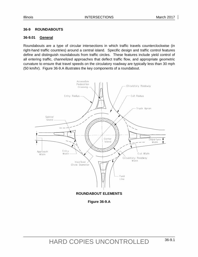
Illinois INTERSECTIONS March 2017
36-9.1 HARD COPIES UNCONTROLLED
36-9 ROUNDABOUTS
36-9.01 General
Roundabouts are a type of circular intersections in which traffic travels counterclockwise (in right-hand traffic countries) around a central island. Specific design and traffic control features define and distinguish roundabouts from traffic circles. These features include yield control of all entering traffic, channelized approaches that deflect traffic flow, and appropriate geometric curvature to ensure that travel speeds on the circulatory roadway are typically less than 30 mph (50 km/hr). Figure 36-9.A illustrates the key components of a roundabout.
ROUNDABOUT ELEMENTS
Figure 36-9.A
Illinois INTERSECTIONS March 2017
36-9.2 HARD COPIES UNCONTROLLED
When operating within their capacity, roundabouts typically operate with lower vehicle delays than other intersection forms and control types. With no conflicts within a roundabout it is unnecessary for traffic to come to a complete stop. When queues exist at one or more approaches, traffic within the queues usually continues to move, and this is typically more tolerable to drivers than a stopped or standing queue.
Studies have shown that compared to other types of intersections, roundabouts have:
Improved safety: • Elimination of high conflict angles; • Lower operating speeds; and • Fewer vehicular conflict points.
Reduced congestion: • Efficient during peak hours and other times, and • Typically less delay.
Reduced pollution and fuel use: • Fewer stops and hard accelerations, and • Less time idling.
Reduced costs: • No signal equipment to install, power, and maintain, although some savings may be
offset by the need and cost of illumination; • Smaller roundabouts may require less right-of-way than traditional intersections; and • Often less pavement needed.
Complement other common community values: • Quieter operation, and • More functional and aesthetically pleasing.
Public acceptance of roundabouts is often one of the biggest challenges facing a jurisdiction that is planning to install its first roundabout. Without the benefit of explanation or first-hand experience and observation, the public is likely to incorrectly associate roundabouts with older, nonconforming traffic circles that they have either experienced or about which they have heard. Equally possible, without adequate education, the public (and agencies alike) will often have a natural hesitation or resistance against changes in their driving behavior and driving environment. In this situation, a proposal to install a roundabout may initially experience a negative public reaction. However, the history of the first few roundabouts installed in the United States also indicated that public attitude toward roundabouts improved significantly after construction. A survey conducted of jurisdictions across the United States reported a significant negative public attitude toward roundabouts prior to construction (68% of the responses were negative or very negative), but a positive attitude after construction (73% of the responses were positive or very positive).

Illinois INTERSECTIONS March 2017
36-9.3 HARD COPIES UNCONTROLLED
36-9.02 Roundabout Selection
36-9.02(a) Comparison of Performance of Alternative Intersection Types.
A roundabout is often compared to other intersection types, usually either a stop- or signal-controlled intersection. To simplify the selection process, the following generalized information is offered for a planning-level operational comparison of control modes:
• A roundabout will almost always provide a higher capacity and lower delays than all-way stop-controlled operating with the same traffic volumes.
• A roundabout is unlikely to offer better performance in terms of lower overall delays than two-way stop control (TWSC) at intersections with minor movements (including cross-street entry and major-street left turns) that are not experiencing, nor predicted to experience, operational problems under TWSC.
• A single-lane roundabout may be assumed to operate within its capacity at any intersection that does not exceed the peak-hour volume warrant for signals.
• A roundabout that operates within its capacity will generally produce lower delays than a signalized intersection operates with the same traffic volumes and right-of-way limitations.
Unlike traffic signal control, there are no warrants for roundabouts currently included in the ILMUTCD. Each roundabout must be justified on its own merits as the most appropriate intersection treatment alternative.
36-9.02(b) Selection Consideration Factors
In determining whether to use a roundabout or a more traditional intersection at a site, consider the following:
1. Safety. The frequency of crashes at an intersection is related to the number of conflict points at an intersection, as well as the magnitude of conflicting flows at each conflict point. A conflict point is a location where the paths of two vehicles, or a vehicle and a bicycle or pedestrian diverge, merge, or cross each other. For example, the number of vehicle-vehicle conflict points for four-leg intersections drops from 32 to 8 with roundabouts, a 75% decrease. Fewer conflict points mean fewer opportunities for collisions. Also, a roundabout has zero vehicle crossing points.
The severity of a collision is determined largely by the speed of impact and the angle of impact. The higher the speed and the higher the angle of impact the more severe the collision. Roundabouts reduce in severity or eliminate many severe conflicts that are present in traditional intersections.
2. Construction Costs. The costs of installing roundabouts will vary significantly from site to site. A roundabout may cost more or less than a traffic signal, depending on the amount of new pavement area and the extent of other roadway work required. At some existing unsignalized intersections, a traffic signal can be installed without significant
Illinois INTERSECTIONS March 2017
36-9.4 HARD COPIES UNCONTROLLED
modifications to the pavement area or curbs. In these instances, a roundabout is likely to be more costly to install than a traffic signal, as the roundabout can rarely be constructed without significant pavement and curb modifications. Consideration of maintenance and power should be included with the long term signal costs.
However, at new sites, and at signalized intersections that require widening at one or more approaches to provide additional turn lanes, a roundabout can be a comparable or less expensive alternative. While roundabouts typically require more pavement area at the intersection, they may require less pavement width on the upstream approaches and downstream exits if multiple turn lanes associated with a signalized intersection can be avoided. The cost savings of reduced approach roadway widths is particularly advantageous at interchange ramp terminals and other intersections adjacent to grade separations where wider roads may result in larger bridge structures.
In most cases, a roundabout is more expensive to construct than the two-way or all-way stop-controlled intersection alternatives.
3. Movements. Roundabouts tend to treat all movements at an intersection equally. Each approach is required to yield to circulating traffic, regardless of whether the approach is a local street or major arterial. In other words, all movements are given equal priority. This may result in more delay to the major movements than might otherwise be desired.
This problem is most acute at the intersection of high-volume major streets with low- to medium-volume minor streets (e.g., major arterial streets with minor collectors or local streets). Therefore, the overall street classification system and hierarchy should be considered before selecting a roundabout (or stop-controlled) intersection. This limitation should be specifically considered on emergency response routes in comparison with other intersection types and control. The delays depend on the volume of turning movements and should be analyzed individually for each approach.
4. Vehicle Delay and Queue Storage. When operating within their capacity, roundabout intersections typically operate with lower vehicle delays than other intersection forms and control types. With a roundabout, it is unnecessary for traffic to come to a complete stop when no conflicts are present.. Where there are queues on one or more approaches, traffic within the queues usually continues to move. This. is typically more tolerable to drivers than a stopped or standing queue. The performance of roundabouts during off-peak periods is particularly good in contrast to other intersection forms, typically with very low average delays.
5. Signal Progression and Access. It is common practice to coordinate traffic signals on arterial roads to minimize stops and delay to through traffic on the major road. By requiring coordinated platoons to yield to traffic in the circulatory roadway, the introduction of a roundabout into a coordinated signal system may disperse and rearrange platoons of traffic if other conflicting flows are significant, thereby reducing progressive movement. To minimize overall system delay, it may be beneficial to divide the signal system into subsystems separated by the roundabout, assigning each subsystem its own cycle.

Illinois INTERSECTIONS March 2017
36-9.5 HARD COPIES UNCONTROLLED
The traffic performance of the combination roundabout-signal system should be tested in advance with traffic modeling software. In some cases, total delay, stops, and queues will be reduced by the roundabout. The number of available gaps for midblock unsignalized intersections and driveways may also be reduced by the introduction of roundabouts, although this may be offset by the reduced speeds near roundabouts. In addition, roundabouts can enable safe and quick U-turns that can substitute for more difficult midblock left turns, especially where there is no left turn lane.
6. Environmental Factors. Roundabouts may provide environmental benefits if they reduce vehicle delay and the number and duration of stops compared with another alternative. Even where there are heavy volumes, vehicles continue to advance slowly in moving queues rather than coming to a complete stop. This may reduce noise and air quality impacts and fuel consumption significantly by reducing the number of acceleration/deceleration cycles and the time spent idling. In general, if stop or yield control is insufficient, traffic through roundabouts generates less pollution and consumes less fuel than traffic at fixed-time signalized intersections. However, vehicle-actuated signals typically cause less delay, less fuel consumption, and fewer emissions than roundabouts as long as traffic volumes are low. During busy hours, vehicle-actuated signals tend to operate like fixed-time signals, and the percentage of cars that must stop becomes high.
7. Space Requirements. Roundabouts usually require more space for the circular roadway and central island than the rectangular space inside traditional intersections. Therefore, roundabouts may have a significant right-of-way impact on the corner properties at the intersection, especially when compared with other forms of unsignalized intersection. The dimensions of a traditional intersection are typically comparable to the envelope formed by the approaching roadways. However, to the extent that a comparable roundabout would outperform a signal in terms of reduced delay and thus shorter queues, it will generally require less queue storage space on the approach legs.
If a signalized intersection requires long and/or multiple turn lanes to provide sufficient capacity or storage, a roundabout with similar capacity may require less space on the approaches. As a result, roundabouts may reduce the need for additional right-of-way on the links between intersections, at the expense of additional right-of-way requirements at the intersections themselves. The right-of-way savings between intersections may make it feasible to accommodate parking, wider sidewalks, planter strips, wider outside lanes, and/or bicycle lanes in order to better accommodate pedestrians and/or bicyclists. Another space-saving strategy is the use of flared approach lanes to provide additional capacity at the intersection while maintaining the benefit of reduced spatial requirements upstream and downstream of an intersection.
At interchange ramp terminals, paired roundabouts have been used to reduce the number of lanes in freeway over- and underpasses. In compact urban areas, there are typically signalized intersections at both ends of overpass bridges, necessitating two additional overpass lanes to provide capacity and storage at the signalized intersections.

Illinois INTERSECTIONS March 2017
36-9.6 HARD COPIES UNCONTROLLED
8. Older Drivers. Roundabouts assist older drivers by reducing the speed at the intersection (i.e., conditions change more slowly allowing for more time to make proper responses), providing less complicated situations and decision-making, judging gaps is easier and mistakes are rarely fatal, providing less demand to accurately judge speeds of traffic, and reducing the required visual scans.
9. Corner Property Access. Access to corner properties may be restricted or require driveways to be offset at roundabouts due to the prohibition of driveways within the circulatory roadway.
10. Operations and Maintenance Costs. Compared to signalized intersections, a roundabout does not have signal equipment that requires constant power, periodic light bulb and detection maintenance, and regular signal timing updates. Roundabouts, however, can have higher landscape maintenance costs, depending on the degree of landscaping provided on the central island, splitter islands, and perimeter. Illumination costs for roundabouts and signalized intersections are similar.
Drivers sometimes face a confusing situation where they approach a signalized intersection during a power failure, but such failures have minimal temporary effect on roundabouts or any other unsignalized intersections, other than the possible loss of illumination. The service life of a roundabout is significantly longer, approximately 25 years, compared with 10 years for a typical signal.
11. Traffic Calming. A series of roundabouts can have secondary traffic calming effect on streets by reducing vehicular speeds. Speed reduction at roundabouts is caused by geometry rather than by traffic control devices or traffic volume. Consequently, speed reduction can be realized at all times of day and on streets of any traffic volume. It is difficult to speed through an appropriately designed roundabout with raised channelization that forces vehicles to physically change direction. In this way, roundabouts can complement other traffic calming measures.
Roundabouts have also been used successfully at the interface between rural and urban areas where speed limits change. In these applications, the traffic calming effects of roundabouts force drivers to slow and reinforce the notion of a significant change in the driving environment.
12. Aesthetics. Roundabouts offer the opportunity to provide attractive entries or centerpieces to communities. However, hard objects in the central island directly facing the entries are a safety hazard. The portions of the central island and, to a lesser degree, the splitter islands that are not subject to sight-distance requirements offer opportunities for aesthetic landscaping. Pavement textures can be varied on the aprons as well. They can also be used in tourist or shopping areas to facilitate safe U-turns and to demarcate commercial uses from residential areas. Avoid “attractive nuisances” in the central island, which could attract pedestrians to cross the circulating roadway for closer inspection.

Illinois INTERSECTIONS March 2017
36-9.7 HARD COPIES UNCONTROLLED
13. Pedestrian Conflicts. If a queuing analysis determines frequent interruptions from pedestrians to the traffic flow at the exit, causing traffic to regularly back into the circulatory roadway, consideration should be given to a conventionally controlled intersection instead of a roundabout.
Illinois INTERSECTIONS March 2017
36-9.8 HARD COPIES UNCONTROLLED
36-9.02(c) Locations
Consider providing roundabouts at intersections having one of more of the following conditions:
• intersections with high crash rates/high severity rates; • intersection with complex geometry (e.g., more than four approaches); • rural intersections with high-speed approaches; • freeway interchange ramp terminals; • closely spaced intersections; • closely spaced offsetting intersections; • replacement of all-way stops; • replacement of signalized intersections; • at intersections with high left-turn volumes; • replacement of two-way stops with high side-street delay; • intersections with high U-turn movements; • transitions from higher-speed to lower-speed areas (traffic calming); • where aesthetics are important; and • where accommodating older drivers is an objective.
Roundabouts are not appropriate everywhere. Intersections that may not be good candidates include those with topographic or site constraints that limit the ability to provide appropriate geometry, those with highly unbalanced traffic flows (i.e., very high traffic volumes on the main street and very light traffic on the side street), and isolated intersections in a network of traffic signals.
Roundabouts often require more space in the immediate vicinity of the intersection than a comparable stop-controlled or signalized intersection. This space requirement is dictated by a number of factors, including the size and shape of the roundabout (e.g., circular versus noncircular). However in the context of a corridor, the additional space needed in the vicinity of a roundabout may be offset by reduced space needed between intersections.
36-9.02(d) Types
1. Single-lane. A single-lane roundabout can be assumed to operate acceptably if the sum of the entering and circulating volumes for each approach is less than 1000 vph. Maximum entering design speeds based on a theoretical fastest path [fastest path discussed in Section 36-9.04(b)] of 20 mph to 25 mph (32 km/hr to 40 km/hr) are recommended at single-lane roundabouts. Generally, the diameter of the inscribed circle of a single-lane roundabout ranges from 105 ft to 150 ft (32 m to 46 m) with the larger size capable of accommodating a WB-67 (WB-20) design vehicle. The typical maximum service volume is 25,000 vpd.
Single-lane roundabouts are much simpler for bicyclists than multilane roundabouts since they do not require bicyclists to change lanes to make left-turn movements or otherwise select the appropriate lane for their direction of travel. In addition, at single-
Illinois INTERSECTIONS March 2017
36-9.9 HARD COPIES UNCONTROLLED
lane roundabouts, motorists are less likely to cut off bicyclists when exiting the roundabout. These are important factors for selecting a single-lane roundabout over a multi-lane roundabout in the short term, even when long-term traffic predictions suggest that a multilane roundabout may be desirable.
2. Multilane. Multilane roundabouts have at least one approach with at least two lanes on the entries or exits. Multilane roundabout design tends to be less forgiving that single-lane roundabout design. Geometry, pavement markings, and signs must be designed together to create a comprehensive system to guide and regulate road users who are traversing roundabouts.
Key considerations for all multilane roundabouts include:
• Lane arrangements to allow drivers to select the appropriate lane on approach and navigate through the roundabout without changing lanes.
• Alignment of vehicles at the entrance line into the correct lane within the circulatory roadway.
• Accommodation of side-by-side vehicles through the roundabout. • Alignment of the legs to prevent exiting-circulating conflicts. • Accommodation for all travel modes.
At multilane roundabouts, maximum entering design speeds of 25 mph to 30 mph (40 km/hr to 48 km/hr) are recommended based on a theoretical fastest path [fastest path discussed in Section 36-9.04(b)] assuming vehicles ignore all lane lines. Generally, the inscribed circle diameter of a multilane roundabout ranges from 150 ft to 250 ft (46 m to 76 m). Roundabouts with three-or four-lane entries may require larger diameters of 180 ft to 350 ft (55 m to 100 m) to achieve adequate speed control and alignment. The typical maximum service volume for a two-lane roundabout is 45,000 vpd.
3. Mini. With a diameter less than 100 ft, the mini roundabout is smaller than the typical single-lane roundabout. The smaller diameter is made possible by the use of a fully traversable central island to accommodate large vehicles, as opposed to the typical single-lane roundabout where the diameter must be large enough to accommodate a multi-unit within the circulatory roadway (and truck apron if applicable) without it needing to travel over the central island. The small footprint of a mini-roundabout offers flexibility in working within constrained sites. The typical maximum service volume is 15,000 vpd.
36-9.03 Public Involvement
Public acceptance of roundabouts is often one of the biggest challenges facing a jurisdiction that is planning to install its first roundabout, thus the use of Context Sensitive Solution principles is recommended for regions new to roundabout operations. Without the benefit of explanation or first-hand experience and observation, the public (and agencies alike) is likely to incorrectly associate roundabouts with older, non-conforming traffic circles that they have either experienced or heard about.
Illinois INTERSECTIONS March 2017
36-9.10 HARD COPIES UNCONTROLLED
In such a situation, a proposal to install a roundabout may initially experience a negative public reaction. However, the history of roundabouts installed in the United States also indicates that public attitude toward roundabouts typically improves significantly after construction. Surveys conducted by the Insurance Institute for Highway Safety reported a significant negative public attitude toward roundabouts prior to construction (41% oppose), but a positive attitude after construction (63% positive or very positive).
A variety of techniques have been used successfully in the United States to inform and educate the public about new roundabouts. Some of these include public meetings, websites, informational brochures and videos, and announcements in the newspaper or on television and radio. A public involvement process should be initiated as soon as practical, preferably early in the planning stages of a project while other intersection forms are being considered.
The FHWA has brochures promoting roundabouts available for distribution at public meetings as well as informational videos for viewing. If a roundabout has been constructed in the vicinity, make recommendations for the public to visit the site or discuss with officials within the jurisdiction in which the roundabout is located. Include animated traffic software to show roundabout operations. Other states have created informational videos and brochures of their own which they have used successfully.
36-9.04 Geometric Design
The geometric design of a roundabout requires the balancing of competing design objectives. Designing a roundabout is a process of determining the optimal balance between safety provisions, operational performance, accommodation of the design vehicle, and consideration of non-motorized travel modes.
Roundabout design is an iterative process where a variety of design objectives must be considered and balanced within site-specific constraints. Individual geometric components are not independent of each other; the interaction between the components of the geometry is more important than the individual pieces. Favoring one component of design may negatively affect another. When developing a design, the trade-offs of safety, capacity, cost and so on must be recognized and assessed throughout the design process. A common example of such a trade-off is accommodating large trucks on the roundabout approach and entry while maintaining low design speeds. Increasing the entry width or entry radius to better accommodate a large truck may simultaneously increase the speeds that passenger vehicles enter the roundabout. Therefore, the designer must balance these competing needs and may need to adjust the initial design parameters. To both accommodate the design vehicle and maintain low speeds, additional design modifications could be required, such as offsetting the approach alignment to the left or increasing the inscribed circle diameter of the roundabout.
Once a roundabout location, an initial inscribed diameter, and approach alignment are identified, the design can be more fully developed to include establishing the entry widths, circulatory roadways width, and initial entry and exit geometry. Once the initial designs for the entries and exits on each approach have been laid out, performance checks should be undertaken to evaluate the design versus the principles (including fastest path and design vehicle

Illinois INTERSECTIONS March 2017
36-9.11 HARD COPIES UNCONTROLLED
accommodation) to identify any required design refinements. Based on the performance checks, it may be necessary to perform design iterations to adjust the inscribed circle diameter, approach alignments, roundabout locations, and/or entry and exit design to improve the composition of the design.
36-9.04(a) Design Speed
A well-designed roundabout reduces vehicle speeds upon entry and achieves consistency in the relative speeds between conflicting traffic streams by requiring vehicles to negotiate the roundabout along a curved path. Speed management is often a combination of managing speeds at the roundabout itself and managing speeds on the approaching highways. In urban settings, entering vehicles negotiate a curve sharp enough to slow speeds to about 15 mph to 20 mph (25 km/hr to 30 km/hr); in rural settings, entering vehicles may be held to somewhat higher speeds of 30 mph to 35 mph (50 km/hr to 55 km/hr). Within the roundabout and as vehicles exit, low speeds are maintained by the deflection of traffic around the center island and the relatively tight radius of the roundabout at the exit lanes. Low speeds aid in the smooth movement of vehicles into, around, and out of a roundabout.
Maximum entering design speeds based on a theoretical fastest path of 20 mph to 25 mph (30 km/hr to 40 km/hr) are recommended at single-lane roundabouts. At multilane roundabouts, maximum entering design speeds of 25 mph to 30 mph (40 km/hr to 50 km/hr) are recommended based on a theoretical fastest path assuming vehicles ignore all lane lines.
36-9.04(b) Vehicle Paths
1. Natural Path. The natural path is the path approaching vehicles will tend to naturally take through the roundabout geometry, assuming there is traffic in all approach lanes. The natural path does not have sudden changes in curvature. It has transitions between tangents and curves and between consecutive reversing curves. Secondly, it means that consecutive curves should be of similar radius. If a second curve has a significantly smaller radius than the first curve, the driver may be traveling too fast to negotiate the turn and may not be able to stay within the lane.
With single-lane roundabouts, it is relatively simple to achieve the speed objectives. With a single traffic stream entering and circulating, there is no conflict between traffic in adjacent lanes. The outside curb line of the entry is commonly designed curvilinearly tangential to the outside edge of the circulatory roadway. Likewise, the projection of the inside (left) edge of the entry roadway is commonly curvilinearly tangential to the central island. Figure 36-9.B shows a typical single-lane roundabout entrance design.
A good multilane entry design aligns vehicle into the appropriate lane within the circulatory roadway. Likewise, the design of the exits should also provide appropriate alignment to allow drivers to intuitively maintain the appropriate lane. These alignment considerations often compete with the fastest path speed objectives.

Illinois INTERSECTIONS March 2017
36-9.12 HARD COPIES UNCONTROLLED
A useful surrogate used by some practitioners for capturing the effects of entry speed, path alignment, and visibility to the left is the entry (phi) angle. Typically entry angles are between 20° and 40°. The entry (phi) angle is discussed in Section 36-9.4(h).
SINGLE-LANE ROUNDABOUT ENTRY DESIGN
Figure 36-9.B
2. Fastest Path. Fastest path is a critical element in the design of roundabouts. The fastest path is the smoothest, flattest path possible for a single vehicle, in the absence of other traffic and ignoring all lane markings. The fastest path through a roundabout is drawn to ensure that the geometry imposes sufficient curvature to achieve a safe design speed. The fastest path is drawn for a vehicle traversing through the entry, around the central island, and out the relevant exit. The fastest path must be drawn for all approaches and all movements, including left-turn movements. Note that the fastest path methodology does not represent expected vehicle speeds, but rather theoretically attainable entry speeds for design purposes.
Figure 36-9.C illustrates and gives a description of the five fastest paths that must be checked for each approach.
To determine the speed of a roundabout, the fastest path allowed by the geometry is drawn. The design speed of the roundabout is determined from the smallest radius
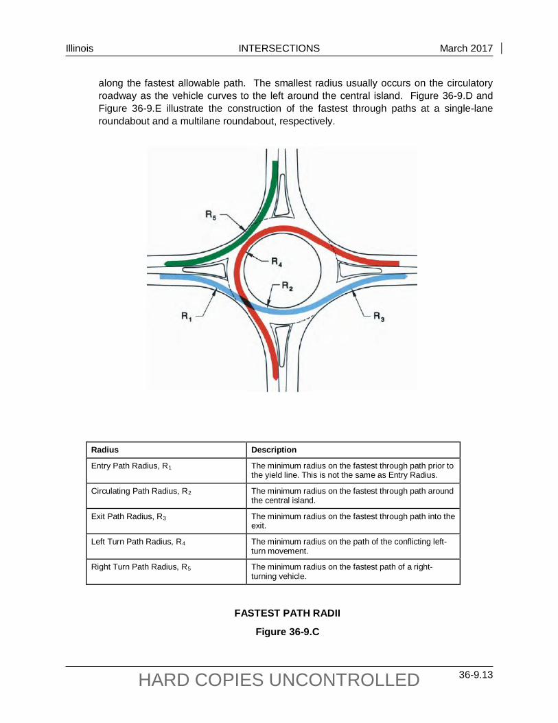
Illinois INTERSECTIONS March 2017
36-9.13 HARD COPIES UNCONTROLLED
along the fastest allowable path. The smallest radius usually occurs on the circulatory roadway as the vehicle curves to the left around the central island. Figure 36-9.D and Figure 36-9.E illustrate the construction of the fastest through paths at a single-lane roundabout and a multilane roundabout, respectively.
Radius Description
Entry Path Radius, R1 The minimum radius on the fastest through path prior to the yield line. This is not the same as Entry Radius.
Circulating Path Radius, R2 The minimum radius on the fastest through path around the central island.
Exit Path Radius, R3 The minimum radius on the fastest through path into the exit.
Left Turn Path Radius, R4 The minimum radius on the path of the conflicting left-turn movement.
Right Turn Path Radius, R5 The minimum radius on the fastest path of a right-turning vehicle.
FASTEST PATH RADII
Figure 36-9.C
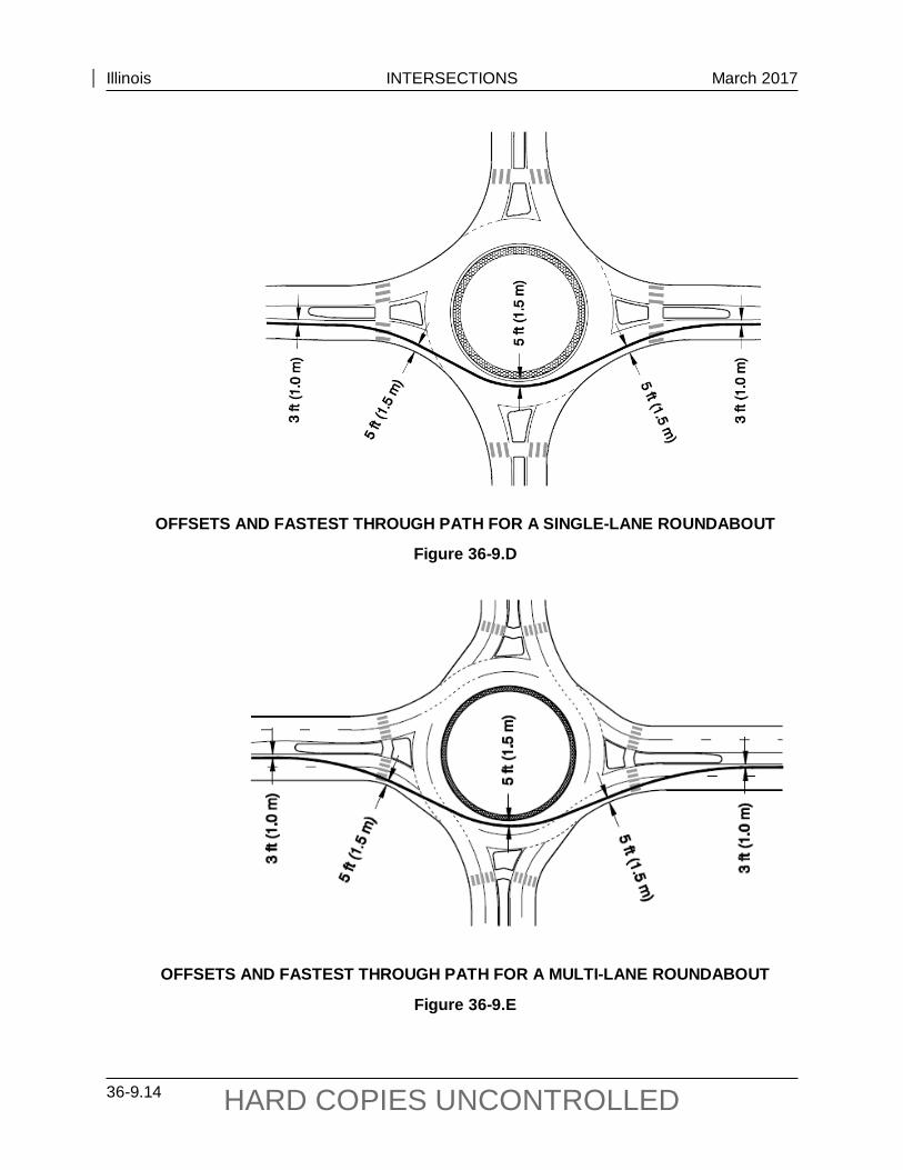
Illinois INTERSECTIONS March 2017
36-9.14 HARD COPIES UNCONTROLLED
OFFSETS AND FASTEST THROUGH PATH FOR A SINGLE-LANE ROUNDABOUT
Figure 36-9.D
OFFSETS AND FASTEST THROUGH PATH FOR A MULTI-LANE ROUNDABOUT
Figure 36-9.E

Illinois INTERSECTIONS March 2017
36-9.15 HARD COPIES UNCONTROLLED
When drawing the fastest path, use spiral curves or place a tangent of approximately 3 seconds of travel distance between consecutive curves to account for the time it takes for a driver to rotate the steering wheel. The entry path radius, R1, is a measure of the deflection imposed on a vehicle prior to entering the roundabout. The ability of the roundabout to control speed at the entry is a proxy for determining the potential safety of the roundabout and whether drivers are likely to yield to circulating vehicles. The construction of the fastest path should begin at least 165 feet (50 m) prior to the entrance line using the appropriate offsets identified in Figure 36-9.D and Figure 36-9.E. The R1 radius should be measured as the smallest best-fit circular curve over a distance of at least 65 ft to 80 ft (20 m to 25 m) near the entrance line. See Figure 36-9.F for additional guidance.
ENTRY PATH RADIUS
Figure 36-9.F
3. Vehicle Path Overlap. Vehicle path overlap occurs within the circulatory roadway of multilane roundabouts when the natural path through the roundabout of one traffic stream overlaps the path of another. The main consequence of vehicle path overlap is reduced capacity because vehicles will tend to not fully utilize both entry lanes. Also path overlap can create safety problems since the potential for sideswipe and single-vehicle crashes is increased. The most common type of path overlap is where vehicles in the left lane on entry are cut off by vehicles in the right lane due to inadequate entry path alignment. Path overlap can also occur upon the exit from the roundabout where the exit radii are too small or the overall exit geometry does not adequately align the vehicle paths into the appropriate lanes. See Figure 36-9.G for examples of vehicle overlap. The desired result of the entry design is for vehicles to naturally be aligned into their correct lane within the circulatory roadway, as illustrated in Figure 36-9.H.

Illinois INTERSECTIONS March 2017
36-9.16 HARD COPIES UNCONTROLLED
PATH OVERLAP AT A MULTILANE ROUNDABOUT
Figure 36-9.G
DESIRABLE VEHICLE PATH ALIGNMENT
Figure 36-9.H
Illinois INTERSECTIONS March 2017
36-9.17 HARD COPIES UNCONTROLLED
36-9.04(c) Speed Consistency
Consistency between the speeds of various movements within the intersection can help to minimize conflicts between adjacent traffic streams. Minimize relative speeds that occur between conflicting traffic streams and between consecutive geometric elements. The speed differential should be no more than approximately 10 mph to 15 mph (15 km/hr to 25 km/hr). These values are typically achieved by providing a low absolute maximum speed for the fastest entering movement.
36-9.04(d) Design Vehicle
Passenger buses should be accommodated within the circulatory roadway without tracking over the truck apron, which could jostle bus occupants. Where the design dictates the need to accommodate large design vehicles within their own lane, there are a number of design considerations that come into play. First a larger inscribed circle diameter and entry/exit radii may be required to accommodate the design vehicle and maintain speed control. Another technique for accommodations on the entry is to provide gore striping, i.e., a striped vane island between the entry lanes. This method can help center the vehicles within the lane and allow a cushion for off-tracking by the design vehicle. Also the use of a mountable truck apron [discussed in Section 36-9.04(i)] around the perimeter of the central island can provide the additional width needed for the off-tracking of the trailer wheels.
36-9.04(e) Non-motorized Design Users
This group includes bicyclists, pedestrians, skaters,, and strollers. There are two general design issues that are most important for non-motorized users. First, lowering the speeds of motorized vehicles make roundabouts both easier to use and safer for non-motorized users. Therefore, the use of low design speeds is recommended in areas where non-motorized users are common. Second, one-lane roundabouts are generally easier and safer for non-motorized users than multilane roundabouts.
See also Sections 36-9.7(a) and 36-9.7(b) for discussion on pedestrian and bicycle accommodations, respectively, and the design of splitter islands to accommodate the same.
36-9.04(f) Size
The inscribed circle diameter is the distance across the circle inscribed by the outer edge of the circulatory roadway, i.e., the sum of the central island diameter plus twice the circulatory roadway width. For single-lane roundabouts, the inscribed circle diameter typically should be at least 105 ft (32 m) to accommodate a WB-50 (WB-15) design vehicle and 130 to 150 ft (40 to 46 m) to accommodate a WB-67 (WB-20) design vehicle. Truck aprons are typically needed to keep the inscribed circle diameter reasonable while accommodating the larger design vehicles. Generally, the inscribed circle diameter of a multilane roundabout ranges from 150 ft to 250 ft (46 to 76 m).
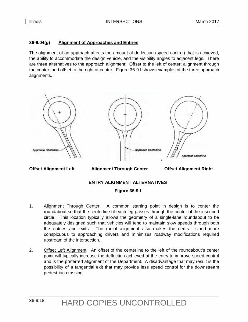
Illinois INTERSECTIONS March 2017
36-9.18 HARD COPIES UNCONTROLLED
36-9.04(g) Alignment of Approaches and Entries
The alignment of an approach affects the amount of deflection (speed control) that is achieved, the ability to accommodate the design vehicle, and the visibility angles to adjacent legs. There are three alternatives to the approach alignment: Offset to the left of center; alignment through the center; and offset to the right of center. Figure 36-9.I shows examples of the three approach alignments.
Offset Alignment Left Alignment Through Center Offset Alignment Right
ENTRY ALIGNMENT ALTERNATIVES
Figure 36-9.I
1. Alignment Through Center. A common starting point in design is to center the
roundabout so that the centerline of each leg passes through the center of the inscribed circle. This location typically allows the geometry of a single-lane roundabout to be adequately designed such that vehicles will tend to maintain slow speeds through both the entries and exits. The radial alignment also makes the central island more conspicuous to approaching drivers and minimizes roadway modifications required upstream of the intersection.
2. Offset Left Alignment. An offset of the centerline to the left of the roundabout’s center point will typically increase the deflection achieved at the entry to improve speed control and is the preferred alignment of the Department. A disadvantage that may result is the possibility of a tangential exit that may provide less speed control for the downstream pedestrian crossing.

Illinois INTERSECTIONS March 2017
36-9.19 HARD COPIES UNCONTROLLED
3. Offset Right Alignment. Approach alignments that are offset to the right of the roundabout’s center point typically do not achieve satisfactory results, primarily due to a lack of deflection and lack of speed control that result from this alignment, thus should be avoided. An offset-right alignment brings the approach in at a more tangential angle and reduces the opportunity to provide sufficient entry curvature. Vehicles may enter the roundabout too fast and are less likely to yield to vehicles in the circulating roadway.
4. Approach Curve. As long as the offset left alignment is utilized, simple entry curves will provide sufficient deflection to reduce entry speeds. With the offset left alignment, additional approach curves should not be needed. With a radial design or if high entry speeds exist, an S-curve or a series of reverse curves may be needed to slow approaching vehicles. Do not superelevate the approach curves as superelevation would counter the affect curve deflection has for speed control. High entry speed design is discussed in more detail under Section 36-9.4(t), “Rural Roundabouts.”
36-9.04(h) Entry Design
1. Single-lane Entry Design. The design of the entry curvature should balance the competing objectives of speed control, adequate alignment of the natural paths, and the need for appropriate visibility lines. The entry curb radius should produce a maximum design speed of 20 mph to 25 mph (30 km/hr to 40 km/hr) on the theoretical fastest path. The entry curb radius should not be confused with the entry path curve, (R1 in Figure 36-9.C) defined by the fastest vehicular travel path through the entry geometry.
The typical design for the entry curb radius for single lane entry approach alignment is to align the outside (right) curb line of the entry curvilinearly tangential to the outside edge of the circulatory roadway. Likewise, the projection of the inside (left) edge of the entry roadway is commonly curvilinearly tangential to the central island. Figure 36-9.A shows the components discussed. The entry radius at urban single-lane entries typically range from 50 ft to 100 ft (15 m to 30 m). The entry curb radius should produce an appropriate design speed on the fastest vehicular path.
Entry from high-speed approaches is started upstream by establishing designs which encourage drivers to slow down in advance of the roundabout. A recommended method to achieve speed reduction is through the use of successive reverse curves. An acceptable speed change on successive geometric elements through the approach is approximately 12 mph (20 km/hr). Tangent segments must be place between reverse curves to allow drivers to rotate the steering wheel between the reverse curves. Refer to the fourth point under Section 36-9.04(t) for further direction on high-speed approaches.
Another important principle in the design of an entry is sight distance and visibility. The angle of visibility to the left must be adequate for entering drivers to comfortably view oncoming traffic from the immediate upstream entry or from the circulatory roadway. Sections 36-9.4(o) and 36-9.4(p) discuss sight distance issues.

Illinois INTERSECTIONS March 2017
36-9.20 HARD COPIES UNCONTROLLED
2. Multilane Entry Design. The entry geometry should provide adequate horizontal curvature to channelize drivers into the circulatory roadway to the right of the central island. The desired result of the entry design is for vehicles to naturally be aligned into their correct lane within the circulatory roadway.
The use of small entry radii [less than 45 ft (14 m)] at multilane roundabout entries may produce low entry speeds, small fastest path radii (R1), and reduced capacity, but often leads to vehicle path overlap [discussed in Section 36-9(b)] on the entry, since the geometry of the outside (right) lane tends to lead vehicles into the inside (left) circulatory lane. See Figure 36-9.J. Values of R1 in the range of 175 ft to 275 ft (53 m to 84 m) are generally preferable. This results in a design speed of 25 mph to 30 mph (40 km/hr to 50 km/hr).
A common technique to promote good path alignment for multilane entry approaches is to use a compound curve or curve followed by a tangent. This design consists of an initial small-radius entry curve [65 ft to 120 ft (20 m to 35 m)] set back at least 20 ft (6.0 m) from the edge of the circulatory roadway. A short section of large-radius [greater than 150 ft (45 m)] or a tangent is fitted between the entry curve and the circulatory roadway to align vehicles into the proper circulatory lane at the entrance line. See Figure 36-9.K for a layout of the entry curve described above.
3. Entry Angle Phi (Φ). A useful surrogate used by some practitioners for capturing the effects of entry speed, path alignment, and visibility to the left is the entry angle phi (Φ). Typically Φ entry angles are between 20° and 40°. Refer to the Wisconsin DOT Roundabout Guide for the uses of the phi angle.
36-9.04(i) Entry Width
1. Single-lane Entries. Entry width at single lane entries is measured from the point where the entrance line intersects the left edge of traveled way to the right edge of the traveled way, along a line perpendicular to the right curb line as shown in Figure 36-9.A. Typical entry widths for single-lane entrances range from 14 ft to 18 ft (4.5 m to 5.5 m). The entry is often widened through a flare from the upstream approach width.
2. At Multilane Entries. A typical entry width for a two-lane entry ranges from 24 ft to 30 ft (7.5 m to 9 m) and 36 ft to 45 ft (11 m to 14 m) for a three-lane entry. The entry width should be primarily determined based upon the number of lanes identified in the operational analysis combined with the turning requirements for the design vehicle.

Illinois INTERSECTIONS March 2017
36-9.21 HARD COPIES UNCONTROLLED
ENTRY VEHICLE PATH OVERLAP
Figure 36-9.J
MINOR APPROACH OFFSET TO INCREASE ENTRY DEFLECTION
Figure 36-9.K

Illinois INTERSECTIONS March 2017
36-9.22 HARD COPIES UNCONTROLLED
36-9.04(j) Circulatory Roadway Width
The required width of the circulatory roadway is determined from the number of entering lanes and the turning requirements of the design vehicle. Except opposite a right-turn only lane, the circulating width should be at least as wide as the maximum entry width and up to 120% of the maximum entry width.
1. Single-lane Roundabouts. For single-lane roundabouts, the circulatory roadway width usually remains constant throughout the roundabout. Typically circulatory roadway widths range from 16 ft to 20 ft (5.0 m to 6.0 m). A truck apron will often be needed within the central island to accommodate larger design vehicles, but maintain a relatively narrow circulatory roadway to adequately constrain vehicle speeds. Additional discussion of truck aprons is provided in Section 36-9.04(l). To avoid jostling passengers the circulatory roadway, width should be wide enough to accommodate a bus without use of the truck apron.
2. Multilane Roundabouts. The circulatory roadway width is usually governed by the design criteria relating to the types of vehicles that may need to be accommodated adjacent to one another through a multilane roundabout. It is acceptable for multi-unit vehicles to encroach upon adjacent lanes. Multilane circulatory roadway lane widths typically range from 14 ft to 16 ft (4.5 m to 5.0 m).
36-9.04(k) Central Island
The central island is the raised non-traversable area (except for mini-roundabouts and the truck apron) surrounded by the circulatory roadway. If a truck apron is provided the truck apron is part of the central island. The island is typically landscaped for aesthetic reasons and raised about 3 ft to enhance driver recognition of the roundabout upon approach. A circular central island is preferred because the constant radius circulatory roadway helps promote constant speeds around the central island, but oval or irregular shapes can be used at irregularly shaped intersections such as offsetting intersections.
Roundabouts in rural environments typically need larger central islands than urban roundabouts to enhance their visibility, accommodate larger design vehicles, enable better approach geometry to be designed in the transition from higher speeds, and be more forgiving to errant vehicles.
Avoid “attractive nuisances” in the central island, which could encourage pedestrians to cross the circulating roadway for closer inspection.
36-9.04(l) Truck Aprons
A truck apron provides additional paved area to allow the over-tracking of large semi-trailer vehicles upon the central island without compromising the deflection for smaller vehicles. A traversable truck apron is typical for most roundabouts to accommodate large vehicles while minimizing other roundabout dimensions. The truck apron should be designed such that they
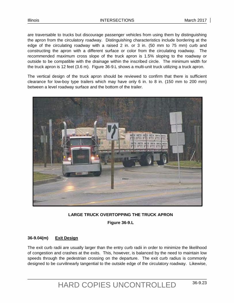
Illinois INTERSECTIONS March 2017
36-9.23 HARD COPIES UNCONTROLLED
are traversable to trucks but discourage passenger vehicles from using them by distinguishing the apron from the circulatory roadway. Distinguishing characteristics include bordering at the edge of the circulating roadway with a raised 2 in. or 3 in. (50 mm to 75 mm) curb and constructing the apron with a different surface or color from the circulating roadway. The recommended maximum cross slope of the truck apron is 1.5% sloping to the roadway or outside to be compatible with the drainage within the inscribed circle. The minimum width for the truck apron is 12 feet (3.6 m). Figure 36-9.L shows a multi-unit truck utilizing a truck apron.
The vertical design of the truck apron should be reviewed to confirm that there is sufficient clearance for low-boy type trailers which may have only 6 in. to 8 in. (150 mm to 200 mm) between a level roadway surface and the bottom of the trailer.
LARGE TRUCK OVERTOPPING THE TRUCK APRON
Figure 36-9.L
36-9.04(m) Exit Design
The exit curb radii are usually larger than the entry curb radii in order to minimize the likelihood of congestion and crashes at the exits. This, however, is balanced by the need to maintain low speeds through the pedestrian crossing on the departure. The exit curb radius is commonly designed to be curvilinearly tangential to the outside edge of the circulatory roadway. Likewise,

Illinois INTERSECTIONS March 2017
36-9.24 HARD COPIES UNCONTROLLED
the projection of the inside (left) edge of the exit roadway is commonly curvilinearly tangential to the central island.
1. Single-lane Exits. Single-lane exits in urban environments should be designed to enforce slow exit path speeds to maximize safety for pedestrians crossing the exiting stream. Pedestrian activities should be considered at all exits except where separate pedestrian facilities or other restrictions eliminate the likelihood of pedestrian activity in the foreseeable future.
For designs using an offset-left approach alignment, the exit design may require much larger radii, ranging from 300 ft to 800 ft (90 m to 245 m) or greater. These radii may provide acceptable speed through the pedestrian crossing area given that the acceleration characteristics of the vehicles will typically result in a practical limit to the speeds that can be achieved on the exit. The fastest-path methodology can be used to verify the exit speed.
2. Multilane Exits. Inadequate horizontal design of the exits can result in exit vehicle path overlap. If the exit radius on a multilane exit is too small, traffic on the inside of the circulatory roadway will tend to exit into the outside exit lane on more comfortable turning radius causing vehicle path overlap, similar to that occurring at entries.
36-9.04(n) Splitter Islands
Purposes of a splitter island are to provide refuge for pedestrians, assist in controlling speeds, guide traffic into the roundabout, physically separate entering and exiting traffic streams, control access, and deter wrong-way movements. Additionally, splitter islands can be used as a place for mounting signs. Splitter islands should be provided on all the legs of a roundabout.
A properly designed splitter island deflects traffic and positions vehicles into a correct alignment to enter the circulatory roadway. This deflection is critical to slowing vehicles before they enter the circulatory roadway. The splitter island should have enough curvature to block a direct path to the central island for approaching vehicles.
When used as a pedestrian refuge, splitter islands shall be a minimum of 6 ft (1.8 m) and preferably 8 ft (2.4 m) from the back of the curb to the back of the curb within the pedestrian refuge area. The total length of the raised island should generally be at least 50 ft (15 m), although 100 ft (30 m) is desirable, to provide sufficient protection for pedestrians and to alert approaching drivers to the geometry of the roundabout. On higher speed roadways, splitter island lengths of 150 ft (45 m) or more are often beneficial. See Figure 36-9.M.
The raised portion of the island controls access to adjacent driveways. Refer to Section 36-9.5(e) for a discussion on access control strategies for the approach and departure of a roundabout.
If the roadway does not have a median at the approach to the splitter island, the approach should have a corrugated median and the nose should be ramped.

Illinois INTERSECTIONS March 2017
36-9.25 HARD COPIES UNCONTROLLED
MINIMUM SPLITTER ISLAND DIMENAIONS
Figure 36-9.M
36-9.04(o) Stopping Sight Distance
Stopping sight distance should be provided at every point within a roundabout and on each entering and exiting approach.
36-9.04(p) Intersection Sight Distance
Intersection sight distance is the distance required for a driver without the right-of-way to perceive and react to the presence of conflicting vehicles. Intersection sight distance is achieved through the establishment of sight triangles that allow a driver to see and safely react to potentially conflicting vehicles. The only locations requiring evaluation of intersection sight distance within roundabouts are the entries.
The sight triangle is bound by a length of roadway defining a limit away from the intersection on each of the two conflicting approaches and by a line connecting those two limits. For roundabouts, these legs should be assumed to follow the curvature of the roadway, and thus distances should be measured not as straight lines but as distances along the vehicular path.
Figure 36-9.N presents a diagram showing the method for determining intersection sight distance. The following two subsections discuss each of the approaching sight limits.

Illinois INTERSECTIONS March 2017
36-9.26 HARD COPIES UNCONTROLLED
INTERSECTION SIGHT DISTANCE
Figure 36-9.N
1. Approach Leg of Sight Triangle. The length of the approach leg of the sight triangle
should be limited to 50 ft (15 m). This value is intended to require vehicles to slow down prior to entering the roundabout, which supports the need to slow down and yield at the roundabout entry and allows drivers to focus on the pedestrian crossing prior to entry.
2. Conflicting Leg of Sight Triangle. A vehicle approaching an entry to a roundabout faces conflicting vehicles within the circulating roadways and on the immediate upstream entry. In most cases it is best to provide no more than the minimum required intersection sight distance on each approach. Excessive intersection sight distance can lead to higher vehicle speeds that reduce the safety of the intersection for all road users.
Section 6.7.3.2 of NCHRP Report 672, Roundabouts: An Informational Guide, defines the limits of the intersection sight triangle and the methodology of calculating the lengths of each leg.
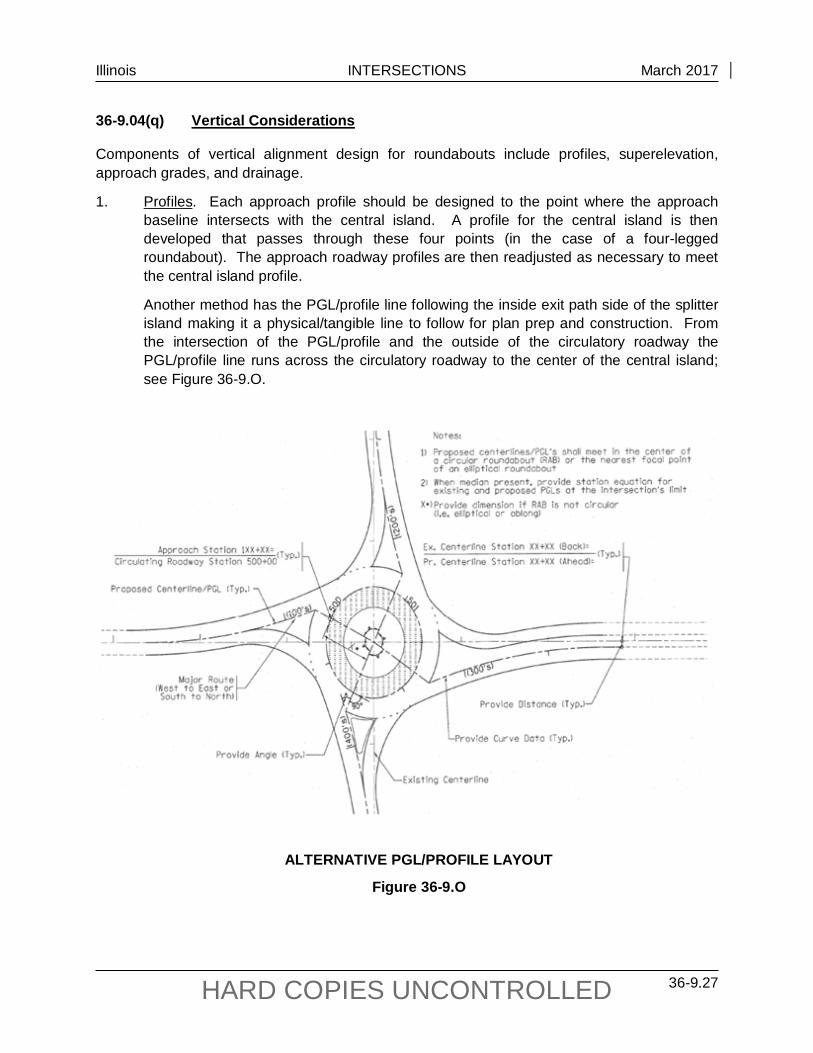
Illinois INTERSECTIONS March 2017
36-9.27 HARD COPIES UNCONTROLLED
36-9.04(q) Vertical Considerations
Components of vertical alignment design for roundabouts include profiles, superelevation, approach grades, and drainage.
1. Profiles. Each approach profile should be designed to the point where the approach baseline intersects with the central island. A profile for the central island is then developed that passes through these four points (in the case of a four-legged roundabout). The approach roadway profiles are then readjusted as necessary to meet the central island profile.
Another method has the PGL/profile line following the inside exit path side of the splitter island making it a physical/tangible line to follow for plan prep and construction. From the intersection of the PGL/profile and the outside of the circulatory roadway the PGL/profile line runs across the circulatory roadway to the center of the central island; see Figure 36-9.O.
ALTERNATIVE PGL/PROFILE LAYOUT
Figure 36-9.O

Illinois INTERSECTIONS March 2017
36-9.28 HARD COPIES UNCONTROLLED
2. Superelevation/Cross Slope. Two primary methods for the superelevation of the circulating roadway are recommended: outward sloping or crowned circulating roadway. Outward sloping is the most common type of vertical design, especially for single-lane roundabouts. Outward sloping means the pavement slopes away from the central island. When the outward sloping cross section is used, the circulating roadway is graded independently of each approach, with the circulatory roadway draining outward with a grade of 1.5% to 2%.
Crowned circulatory roadways consists of approximately 2/3 width sloping toward the central island and 1/3 width sloping outward. Exact location of the crown may vary according to the joint plan and future staging. The cross slopes should range from 1.5% to 2%. Placing the crown 2/3 of the width into the circulatory roadway is more compatible for lowboy trailers by allowing more height to raise the low-boy bed. The intent is to minimize the occurrence of the trailer bottoming-out upon the curb of the truck apron. Figure 36-9.P shows an example of a cross section of a roundabout with a crowned circulatory roadway.
3. Approach Grades. Grades of the approach legs should follow guidelines in Section 36-1.06(a).
4. Drainage. If the circulating roadway slopes away from the central island, inlets will generally be placed on the outer curb line of the roundabout. For circulating roadways that are crowned, drainage inlets will be required along the central island, since a portion of the circulating roadway drains toward the central island.
CIRCULATORY ROADWAY AND TRUCK APRON CROSS SECTION
Figure 36-9.P

Illinois INTERSECTIONS March 2017
36-9.29 HARD COPIES UNCONTROLLED
36-9.04(r) Bus Stop Locations
Transit considerations at a roundabout are similar to those at a conventional intersection.
1. Nearside stops. If an approach has only one lane and capacity is not an issue on that entry, the bus stop could be located at the pedestrian crossing in the lane of traffic. Do not locate the bus stop at the pedestrian crossing for entries with more than one lane because vehicles in the lane next to the bus may not see pedestrians as pedestrians use the crossing. For multilane approaches, a nearside bus stop can be included in the travel lane as long as it is set back at least 50 ft (15 m) from the crosswalk.
2. Far-side stops. Bus stops should be located carefully to minimize the probability of vehicle queues spilling back into the circulatory roadway. This typically means that bus stops located on the far side of the intersection need to have pullouts or be further downstream than the splitter island. If a pullout is used, position the pullout beyond the pedestrian crossing to improve visibility of pedestrians to other exiting vehicles. Pedestrian access routes to transit should be designed for safety, comfort, and convenience. If demand is significant (e.g., near a station or terminus), pedestrian crossing capacity should be taken into account.
36-9.04(s) Right-turn Bypass Lane
A right-turn bypass lane allows right-turning traffic to bypass the roundabout, providing additional capacity for the through and left-turn movements at the approach. Bypass lanes are most beneficial when the demand of an approach exceeds its capacity and a significant proportion of the traffic is turning right. In some cases, the use of a right-turn bypass lane can avoid the need to build an additional entry or circulatory lane. To determine if a right-turn bypass lane should be used, the capacity and delay calculations should be performed. A right-turn bypass lane should only be implemented where needed, especially in urban areas with pedestrian and bicycle activities. There are two options for right-turn bypass lanes: Figure 36-9.Q gives examples of both a full and partial bypass lane.
1. Full bypass. A full bypass lane carries the bypass lane parallel to the adjacent exit roadway, and then merges it into the main exit lane.
2. Partial bypass. A partial bypass lane, with or without a vane, provides a yield-controlled entrance onto the adjacent exit roadway. This option is generally better for bicyclists and pedestrians and is recommended as the preferred option in urban areas where pedestrians and bicyclists are prevalent. The partial bypass lane should direct the vehicle to the adjacent leg’s splitter island to minimize the likelihood of the driver using the bypass lane as a though lane.

Illinois INTERSECTIONS March 2017
36-9.30 HARD COPIES UNCONTROLLED
RIGHT TURN BYPASS LANES (Top view, full bypass. Bottom view, partial bypass)
Figure 36-9.Q

Illinois INTERSECTIONS March 2017
36-9.31 HARD COPIES UNCONTROLLED
36-9.04(t) Rural Roundabouts
Roundabouts located on rural roads often have special design considerations because approach speeds are higher than for urban or local streets, and drivers are less likely to expect to encounter speed interruptions. The primary safety concern in rural locations is to make drivers aware of the roundabout with ample distance to comfortably decelerate to the appropriate speed. The design of a roundabout in a high-speed environment typically employs all of the techniques of a roundabout in a lower-speed environment, with greater emphasis on the items presented below.
1. Visibility. The potential for single-vehicle crashes can be minimized with attention to proper visibility of the roundabout and its approaches. Where possible, the geometric alignment of approach roadways should be constructed to maximize the visibility of the central island and the shape of the roundabout. Where adequate visibility cannot be provided solely through geometric alignment, additional treatments (signing, pavement markings, advanced warning beacons, etc.) should be considered. Note that many of these treatments are similar to those that would be applied to rural stop-controlled or signalized intersections.
2. Curbing. Narrow shoulder widths and curbs on the outside edges of pavement generally give drivers a sense they are entering a more controlled setting, causing them to naturally slow down. Thus, when installing a roundabout on an open rural highway, curbs should be provided at the roundabout and on the approaches, and consideration should be given to reducing shoulder widths. Extend the curbing from the approach for at least the length of the required deceleration to the roundabout.
3. Splitter Islands. Splitter islands should generally be extended upstream of the entrance line to the point at which entering drivers are expected to begin decelerating comfortably. A minimum of 200 feet is recommended for high-speed approaches.
4. Approach Curves. The radius of an approach curve (and subsequent vehicular speeds) has a direct impact on the frequency of crashes at roundabouts. A study has shown that decreasing the radius of an approach curve generally decreases the approaching rear-end vehicle crash rate and the entering-circulating and exiting-circulating vehicle crash rates. On the other hand, decreasing the radius of an approach curve may increase the single vehicle crash rate on the curve. This may encourage drivers to cut across lanes and increase sideswipe crashes on the approach.
One method to achieve speed reduction in order to reduce crashes at the roundabout is the use of successive reverse curves on the approaches; see Figure 36-9.R. By limiting the reduction in the design speed on successive reverse curves to approximately 12 mph (20 km/hr), the crash rate was reduced. Provide tangents between successive reverse curves of approximately 3 seconds of travel distance to allow a change in rotation of the steering wheel and do not superelevate the curves. A report recommended the approach speed be limited to no more than 35 mph (60 km/hr) immediately prior to the entry curves to minimize high-speed rear-end crashes and entering-circulating vehicle crashes.

Illinois INTERSECTIONS March 2017
36-9.32 HARD COPIES UNCONTROLLED
USE OF SUCCCESSIVE CURVES ON HIGH-SPEED APPROACHES
Figure 36-9.R
36-9.04(u) Mini-roundabouts
A mini-roundabout is characterized by a smaller diameter and traversable island. Mini-roundabouts are best suited to environments where speeds are already low and environmental constraints would preclude the use of a larger roundabout with a raised central island.
Mini-roundabouts operate in the same manner as larger roundabouts, with yield control on all entries and counterclockwise circulation around a central island. Due to the small footprint, large vehicles are typically required to travel over the fully traversable central island, but buses should be accommodated within the circulatory roadway to avoid jostling passengers by running over a traversable central island.
36-9.04(v) Staging Single-Lane versus Multilane Roundabout
When projected traffic volumes indicate that a multilane roundabout is required for future year conditions, engineers should evaluate the duration of time that a single-lane roundabout would operate acceptably before requiring additional lanes. Where a single lane roundabout should be sufficient for much of its design life, engineers should evaluate whether it is best to first construct a single-lane roundabout until traffic volumes dictate the need for expansion to a multilane roundabout. One reason to stage the construction of a multilane roundabout is that future traffic predictions may never materialize due to the significant number of assumptions that must be made when developing volume estimates for a 20 or 30 year design horizon. Also non-motorized users are better accommodated on single-lane roundabouts.
Single lane roundabouts are generally simpler for motorists to learn and are more easily accepted in new locations. This, combined with fewer vehicle conflicts, should result in a better overall crash experience and allow for a smooth transition into the ultimate multilane build-out of the intersection.
Illinois INTERSECTIONS March 2017
36-9.33 HARD COPIES UNCONTROLLED
When considering an interim single-lane roundabout, the engineer should evaluate the right-of-way and geometric needs for both the single-lane and multilane configurations.
Two methods to expand from a single-lane to a double lane roundabout:
1. Expansion to the outside. When using this option, care should be taken to provide adequate geometric features, including entry and splitter island design, to ensure that speed reduction and adequate natural paths can be provided at build-out. This configuration has the potential to be less of a disruption to vehicular traffic during the expansion since the majority of the improvements are on the outside of the roadway.
2. Expansion to the inside. Expansion to the inside involves adding any necessary lanes for the ultimate configuration to the inside of the interim roundabout configuration, with the outer curbs and inscribed circle diameter remaining the same in both interim and ultimate configurations. This allows the engineer to set the outer limits of the intersection during the initial construction and limits the future construction impacts to surrounding properties during widening, as sidewalks. drainage features, and outer curb lines will not typically require adjustments.
36-9.05 Operational Performance
The operational performance of roundabouts is relatively simple, although the techniques used to model performance can be quite complex. A few features are common to the modeling techniques employed by all analysis tools:
• Drivers must yield the right-of-way to circulating vehicles and accept gaps in circulating traffic stream. Therefore, the operational performance of a roundabout is directly influenced by traffic patterns and gap acceptance.
• As with other types of intersections, the operational performance of a roundabout is directly influenced by its geometry
Influences to roundabout operations follow:
1. Gap Acceptance. The operation of vehicular traffic at a roundabout is determined by gap acceptance: Entering vehicles look for and accept gaps in circulating traffic. The low speed of a roundabout facilitates these gap acceptance practices. Furthermore, the operational efficiency (capacity) of roundabouts is greater at lower circulating speeds because of the following two phenomena.
• The faster the circulating traffic, the larger the gaps that entering traffic will comfortably accept. This translates to fewer acceptable gaps and therefore more instances of entering vehicles stopping at the yield line.
• Entering traffic, which is first stopped at the yield line, requires even larger gaps in the circulating traffic in order to accelerate and merge with the circulating traffic. The faster the circulating traffic, the larger this gap must be. This translates into fewer acceptable gaps and therefore longer delays for entering traffic.

Illinois INTERSECTIONS March 2017
36-9.34 HARD COPIES UNCONTROLLED
2. Traffic Flow and Driver Behavior. The capacity of a roundabout decreases as the conflicting flow increases. In general, the primary conflicting flow is the circulating flow that passes directly in front of the subject entry. Exiting flow may also affect a driver’s decision on when to enter the roundabout. This phenomenon is similar to the effect of the right-tuning stream approaching from the left side of a two-way stop-controlled intersection. Another behavioral affect occurs when both the entering and conflicting flow volumes are high. Limited priority (where circulating traffic adjusts its headway to allow entering vehicles to enter) or priority reversal (where entering traffic forces circulating traffic to yield) may occur.
3. Geometry. Geometry plays a significant role in the operational performance of a roundabout in a number of key ways:
• It affects the speed of vehicles through the intersection, thus influencing their travel time by virtue of geometry alone (geometric delay).
• It dictates the number of lanes over which entering and circulating vehicles travel. The width of the approach roadway and entry determine the number of vehicle streams that may form side-by-side at the yield line and govern the rate at which vehicles may enter the circulating roadway.
• It can affect the degree to which flow in a given lane is facilitated or constrained. For example, the angle at which a vehicle enters affects the speed of that vehicle, with entries that are more perpendicular requiring lower speeds and thus longer headway. Likewise, the geometry of multilane entries may influence the degree to which drivers are comfortable entering next to one another.
• It may affect the driver’s perception of how to navigate the roundabout and their corresponding lane choice approaching the entry. Improper lane alignment can increase friction between adjacent lanes and thus reduce capacity. Imbalanced lane flows on an entry can increase the delay and queuing on an entry despite the entry operating below its theoretical capacity.
Lane changes within circulating lanes should not be required other than when a lane is added within the circulatory roadway. A lane added within the circulating roadway does not create any additional conflicts.
36-9.05(a) Entering, Circulating, and Exiting Volumes
The analytic methods in the Highway Capacity Manual allow the assessment of the operational performance of an existing or planned one-lane or two-lane roundabout when given traffic demand levels.
1. Determining Roundabout Flow Rates. The circulating flow rate opposing a given entry is defined as the flow conflicting with the entry flow of that leg. See Exhibit 21-11 of the 2010 Highway Capacity Manual (HCM). For example the movements that contribute to the northbound circulating flow rate (shown as vc,NB in Exhibit 21-11 of the HCM) are the movements that flow in front of the northbound entry, which are the eastbound through,
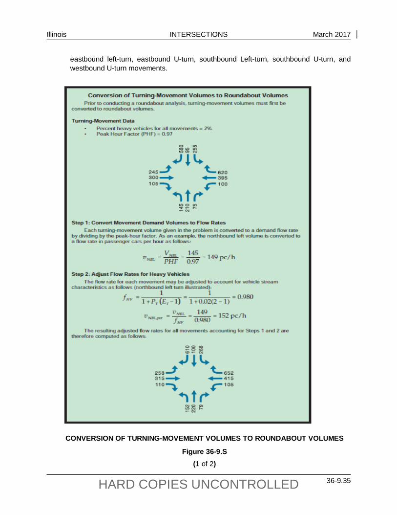
Illinois INTERSECTIONS March 2017
36-9.35 HARD COPIES UNCONTROLLED
eastbound left-turn, eastbound U-turn, southbound Left-turn, southbound U-turn, and westbound U-turn movements.
CONVERSION OF TURNING-MOVEMENT VOLUMES TO ROUNDABOUT VOLUMES
Figure 36-9.S (1 of 2)

Illinois INTERSECTIONS March 2017
36-9.36 HARD COPIES UNCONTROLLED
CONVERSION OF TURNING-MOVEMENT VOLUMES TO ROUNDABOUT VOLUMES
Figure 36-9.S (2 of 2)

Illinois INTERSECTIONS March 2017
36-9.37 HARD COPIES UNCONTROLLED
2. Conversion of Turning-Movement Volumes to Roundabout Volumes. See Figure 36-9.S. After determining the demand flow rate, by dividing by the peak-hour factor, and then adjusting for heavy vehicles to determine the passenger car equivalents, one can determine the entry flow rates, circulating flow rates, and the exiting flow rates.
• Entry flow rates are calculated by summing up the movement flow rates that enter the roundabout. For single-lane roundabouts, all approach volumes are summed together. Additional lane-use calculations are required for multilane roundabouts.
• Circulating flow rates are the sum of all volumes that are expected to conflict with entering vehicles on the subject approach.
• Exiting flow rates are calculated for each leg by summing all flow that will be exiting the roundabout on a particular leg.
The exiting flow rate for a given leg is used primarily in the calculation of conflicting flow for right-turn bypass lanes and in determining queuing at exit–side crosswalks. For example the movements contributing to the southbound exiting flow rate (shown as vex,SB in Exhibit 21-12 of the HCM) are the eastbound right-turn, southbound through, westbound left-turn, and northbound U-turn movements.
36-9.05(b) Capacity
The maximum flow rate that can be accommodated at a roundabout entry depends on two factors: The circulating flow rate in the roundabout that conflicts with the entry flow, and the geometric elements of the roundabout. The larger gaps in the circulating flow are more useful to the entering drivers and more than one vehicle may enter each gap. As the circulating flow increases, the size of the gaps in the circulating flow decreases, thus the rate at which vehicles can enter also decreases.
The geometric elements of the roundabout also affect the rate of entry flow. The most important geometric elements are the width and number of lanes at entry, and the circulatory roadway width within the roundabout. Two entry lanes permit nearly twice the rate of entry flow compared to one lane. A wider circulatory roadway allows vehicles to travel side-by-side or staggered, which creates a tighter group of vehicles, thereby providing longer gaps.
1. Single-lane Roundabout Entry Capacity. A single-lane roundabout can be expected to handle 25,000 vpd and peak-hour flows between 2000 vph and 2500 vph. This rate exceeds 1900 vph, which is the typical single-lane capacity of a signalized intersection. This higher rate is achievable for several reasons. First, this is the total of all the approaches of the roundabout, not a single approach. Second, because of multiple approaches and right turns, much of the traffic does not conflict and may enter the intersection nearly simultaneously.
2. Single-lane Exit Capacity. It is difficult to achieve an exit flow on a single lane of more than 1400 vph, even under good operating conditions for vehicles (i.e., tangential

Illinois INTERSECTIONS March 2017
36-9.38 HARD COPIES UNCONTROLLED
alignment, and no pedestrians or bicyclists). Under normal urban conditions, the exit lane capacity should be in the range of 1200 vph to 1300 vph. Therefore, exit flows exceeding 1200 vph may indicate a lower LOS or the need for a multilane exit.
3. Multilane Roundabout Capacity. For planning purposes, multilane roundabouts (two-lane entries) can be expected to handle ADT’s between 25,000 vpd and 45,000 vpd and peak-hour flows between 2500 vph and 4500 vph.
4. Pedestrian Effects on Entry and Exit Capacity. Pedestrians crossing at a marked crosswalk that have priority over entering motor vehicles can have a significant effect on the entry capacity. In such cases, if the pedestrian crossing volume and circulating volume are known, multiply the vehicular capacity by a factor, fped, according to the relationship shown in Exhibit 21-18 or Exhibit 21-20 of the 2010 Highway Capacity Manual (HCM) for single-lane and double-lane roundabouts, respectively. Note that the effects of conflicting pedestrians on the approach capacity decrease as conflicting vehicular volumes increase, as entering vehicles become more likely to have to stop regardless of whether pedestrians are present. Consult the (HCM) for additional guidance on the capacity of pedestrian crossings if the capacity of the crosswalk itself is an issue. A similar concern may occur at the roundabout exit where pedestrians cross.
36-9.05(c) Capacity Software
IDOT requires the current version of Signalized (and unsignalized) Intersection Design and Research Aid (SIDRA) for capacity analyses of roundabouts. SIDRA closely follows the methods used in the Highway Capacity Manual (HCM), which IDOT requires for computing highway capacity analyses. SIDRA software also includes alternative tools for applications beyond the ability of the HCM.
36-9.05(d) Traffic Control
Vehicles entering the roundabout must yield to the traffic within the circle. A YIELD sign is required at the entry along with the appropriate pavement markings. There is no traffic control within the circular roadway.
36-9.05(e) Access Control
Roundabouts can be used at key public and private intersections to facilitate major movements and enhance access management. Major commercial driveways may be allowed as legs of the roundabout, however, installation of a roundabout strictly for access to private development is discouraged. Minor public and private access points between roundabouts can be accommodated by partially or fully restricted two-way stop-controlled intersections, with the roundabouts providing U-turn opportunities.

Illinois INTERSECTIONS March 2017
36-9.39 HARD COPIES UNCONTROLLED
Most of the principles used for access management at conventional intersections can also be applied at roundabouts. Property access within the vicinity of an individual roundabout intersection must be carefully evaluated. If an access, such as a driveway, is necessary within an intersection a roundabout should be discouraged at the location. As a corollary to this, do not include driveways within the circulating area of a roundabout. Driveways introduce conflicts into the circulating roadway, including acceleration and deceleration. Traditional driveways do not discourage wrong way movements as a splitter island does.
Access points should be no closer to the roundabout intersection than the splitter islands. On a larger consideration, access points near roundabouts are governed by a number of factors:
1. Capacity of the Minor Movements at the Access Point. While roundabouts may allow for fewer lanes between intersections, the traffic pattern that emerges from roundabouts can have a significant impact on existing midblock access. Unlike the platooned flow typically downstream of a signalized intersection, traffic passing in front of an access point downstream of a roundabout should be more randomly distributed. As a result, an access point downstream of a roundabout may have less capacity and higher delay than one downstream of a traffic signal.
2. Need to Provide Left-turn Storage on the Major Street to Serve the Access Point. For all but low-volume driveways, it is desirable to provide separate left-turn storage for access points downstream of a roundabout to minimize the likelihood that a left-turning vehicle could block the major street traffic. If an access point is necessary and left turn access is permitted, it should be located far enough from the splitter island of the roundabout that the required deceleration and storage lengths can be provided.
3. Sight distance needs. A driver at the access point should have proper intersection sight distance. Vehicles within the roundabout should be visible when approaching or departing the roundabout.
36-9.06 Safety
The use of roundabouts is a proven safety strategy for improving intersection safety by eliminating or altering conflict types, reducing crash severity, and causing drivers to reduce speeds as they proceed into and through the intersections. This is true for urban, suburban, and rural environments in replacing two-way stop and signal controls. While overall crash frequencies have been reduced, the crash reductions are most pronounced for motor vehicles, less pronounced for pedestrians, and equivocal for bicyclists and motorcyclists depending on the study and bicycle treatments.
The reasons for the increased safety level at roundabouts are:
• Roundabouts have fewer vehicular conflict points in comparison to conventional intersections and the potential for the most severe types of conflicts, such as right angle and left turn head-on crashes, is greatly reduced with roundabout use.
Illinois INTERSECTIONS March 2017
36-9.40 HARD COPIES UNCONTROLLED
• Lower absolute speeds generally associated with roundabouts decrease the braking distance required to avoid potential conflicts. Low vehicle speeds help reduce crash severity, making fatalities and serious injuries much less common at roundabouts.
• Since most users travel at similar speeds through roundabouts, crash severity can be reduced compared to some traditionally controlled intersections.
• Pedestrians need only cross one direction of traffic at a time at each approach as they traverse roundabouts (i.e., crossing in two stages), as compared with many traditional intersections. Pedestrian-vehicle conflict points are reduced at roundabouts; from the pedestrian perspective, conflicting vehicles come from fewer directions.
NCHRP Report 572, Roundabouts in the United States and NCHRP Report 672, Roundabouts: An Informational Guide include intersection-level crash prediction models to evaluate the safety performance of an existing roundabout relative to its peers, and in the estimation of the expected safety changes, if a roundabout is contemplated for constructions at an existing conventional intersection.
Although the frequency of crashes is most directly tied to volume, the severity is most directly tied to speed. Therefore, careful attention to the design speed of a roundabout is fundamental to attaining good safety performance.
36-9.07 Pedestrian and Bicycle Accommodations
As with the motorized design vehicle, the design criteria for non-motorized potential roundabouts users (bicyclists, pedestrians, wheelchairs, etc.) shall be considered when developing many of the geometric components of a roundabout design. There are two general design issues that are most important for non-motorized users. First, lower motorized vehicle speeds make roundabouts both easier to use and safer for non-motorized users. Second, one-lane roundabouts are generally easier and safer for non-motorized users than multilane roundabouts. When non-motorized users are a significant consideration, do not design a multilane roundabout when a single lane roundabout should be sufficient.
36-9.07(a) Pedestrians
Pedestrian activities shall be considered at all roundabouts except where separate pedestrian facilities or other restrictions eliminate the likelihood of pedestrian activity in the foreseeable future.
Pedestrians desire crossing locations as close to the roundabout as possible to minimize out-of-direction travel. The further the crossing is from the roundabout, the more likely pedestrians will choose a shorter route that may put them in greater danger. In general, at a minimum, locate the pedestrian crossing one car length or approximately 20 feet upstream from the yield point and place the crossing at full vehicle-length-increments from the yield line for crossings further from the yield line.

Illinois INTERSECTIONS March 2017
36-9.41 HARD COPIES UNCONTROLLED
For pedestrian safety the crossing should not be located too far back from the yield line so that entering vehicle speeds are not sufficiently reduced or exiting vehicles are accelerating. It may be appropriate to design the pedestrian crossing at two or three car lengths from the yield point at some multilane entries. At single-lane roundabouts in urban environments, exits should be designed to enforce low exit path speeds to maximize safety for pedestrians crossing the exiting stream.
At roundabouts with multilane pedestrian street crossings, a pedestrian activated signal should be provided for each multilane segment of each pedestrian street crossing. A pedestrian signal found to be effective in increasing yielding rates is the rectangular rapid flashing beacon. Pedestrian hybrid beacons (commonly referred to as HAWK signals) are not recommended for pedestrian signals at roundabouts.
Regardless of the type of pedestrian signal, the operation for a pedestrian crossing a roundabout approach should be done in two stages. A single-stage pedestrian signal can result in excessive amount of delay to vehicular traffic. At two-stage signalized pedestrian crossings, there are two separate pedestrian walk intervals, one for crossing the entry roadway and one for crossing the exit roadway.
Roundabouts with single lane approach and exit legs are not required to provide pedestrian activated signals. If a roundabout consists of multilane and single lane pedestrian crossings consider including pedestrian activated signals at the single lane pedestrian street crossings for consistency.
The raised splitter island width shall be a minimum of 6 ft (1.8 m) wide (from the back-of-curb to the back-of-curb) at the crosswalk to adequately provide shelter for users and to provide the minimum width for the use of detectable warnings within the splitter island.
Roundabout operations at the exit can be affected by pedestrian use of the crosswalk. A queuing analysis at the exit crosswalk may determine that a crosswalk location of more than one vehicle length from the circulatory roadway may be desirable to reduce the likelihood of queuing into the circulatory roadway due to pedestrians crossing. Also, it may be easier for pedestrians to visually distinguish exiting vehicles from circulating vehicles at crosswalks located further from the roundabout. If a queuing analysis determines frequent interruptions from pedestrians to the traffic flow at the exit, causing traffic to regularly back into the circulatory roadway, consideration should be given to a conventionally controlled intersection instead of a roundabout.
The draft Public Rights-of-Way Accessibility Guidelines (PROWAG) from the United States Access Board include a requirement to provide a detectable edge treatment between sidewalks and roundabouts wherever pedestrian crossings are not intended, such as adjacent to the perimeter of the circulatory roadway, along the approaches, or along the exit/entrance radii.
Landscape strips are an effective method to provide a detectable edge treatment. Landscape strips provide many benefits, including increased comfort for pedestrians, room for street furniture and snow storage, and a buffer to allow for the overhang of large vehicles as they navigate the roundabout. Also the setback discourages pedestrians from crossing to the central

Illinois INTERSECTIONS March 2017
36-9.42 HARD COPIES UNCONTROLLED
island or cutting across the circulatory roadway of the roundabout. The setback helps guide pedestrians with vision impairment to the designated crosswalk.
If the sidewalk must be flush with the back of the curb, provide a detectable edge treatment along the street side of the sidewalk. If chains, fences, or railings are used for edge treatment, the bottom of the edge treatments shall be no higher than 15 in. (380 mm) above the sidewalk. Detectable warning surfaces, such as truncated domes, shall not be used for edge treatment because detectable warning surfaces indicate the flush transition between the sidewalk and the roadway. In addition to chains, fences, or railings, low shrubs or grass may be used for edge treatments.
36-9.07(b) Bicycles
Bicyclists’ decisions at roundabouts depend on how the bicyclist chooses to travel through the intersection. If traveling as a vehicle, as is often the case for experienced cyclists and cyclists in lower volume and low speed environments, the decision process mirrors that of motorized vehicles. Effective designs that constrain motorized vehicles to speeds more compatible with bicycle speed, around 15 mph to 20 mph, are much safer for bicyclists. If traveling as a pedestrian, as is often the case for less experienced cyclists and cyclists in higher traffic volume environments, the decision process mirrors that of pedestrians.
Although the best design provides bicyclists the choice of proceeding through the roundabout as either a vehicle or as a pedestrian, in general, bicyclists are better served by being treated by roundabout designers as vehicles. When entering traffic volumes are projected to be large (i.e., greater than 12,000 ADT), look at other options such as shared use-paths, which provide a physical separation from vehicles around the periphery of the roundabout.
If bicycle lanes are provided on the roadway approaches provide a ramp from the roadway to a shared-use path prior to the intersection to allow a bicyclist to exit the roadway and proceed around the intersection safely through the use of cross walks if the bicyclist is uncomfortable mixing with vehicles. Consider bicycle ramps and a shared-use path around the circulatory roadway for bicycle accommodations even if no sidewalks or shared-use paths are proposed approaching the roundabout. Continue the shared-use path around the circulatory roadway, but separate from the circulatory roadway, where bicycle use is expected. Do not provide bike lanes within the circulatory roadway.
For bicycle design considerations through a roundabout; see Section 17-2.04.
36-9.08 Parking
Parking within the circulatory roadway is prohibited. Parking on entries and exits to the roundabout should be set back far enough so as not to hinder roundabout operations or to impair visibility of pedestrians.
Illinois INTERSECTIONS March 2017
36-9.43 HARD COPIES UNCONTROLLED
36-9.09 Illumination
For a roundabout to operate satisfactorily, a driver must be able to enter the roundabout, move through the circulating traffic, and separate from the circulatory stream in a safe and efficient manner. Pedestrians must also be able to safely use the crosswalks. To accomplish this, a driver must be able to perceive the general layout and operation of the intersection in time to make the appropriate maneuvers at all times of the day. Adequate lighting shall therefore be provided at all roundabouts including those in rural locations.
Lighting of roundabouts provides:
1. visibility from a distance for users approaching the roundabout;
2. visibility of the key conflict areas to improve users’ perception of the layout and visibility of other users within the roundabout;
3. additional visibility for signing and pavement markings; and
4. visibility of pedestrians at and within the crosswalks.
The effectiveness of auto headlights is limited in a roundabout due to the constrained curve radius, making the roadway lighting system very important for nighttime visibility of obstructions and hazards. Approach lighting should provide good perception of the presence of the roundabout.
See Section 56-2.08 for more guidance on lighting for roundabouts.
36-9.10 Signing and Delineation
Pavement marking and signs are integral to the design of roundabouts, especially multilane roundabouts. The ILMUTCD, the latest version of FHWA’s Standard Highway Signs, and any applicable state and local standards govern the design and placement of traffic control devices, including signs, pavement markings and signals. Consult the Bureau of Operations or Bureau of Traffic within the respective District of the roundabout location for specific standards for delineating and signing roundabouts.
Entry lanes should be well referenced, especially for multilane roundabouts, which should have cars in their proper lane at the approach so lane changing is not required through circulating lanes. Signs should be located where they have the maximum visibility for road users, but a minimal likelihood of even momentarily obscuring pedestrians and bicyclists.
A YIELD sign is required at the entry along with the appropriate pavement markings. There is no traffic control within the circular roadway.


Illinois INTERSECTIONS October 2015
36-10.1 HARD COPIES UNCONTROLLED
36-10 REFERENCES
1. A Policy on Geometric Design of Highways and Streets, AASHTO, 2011.
2. Highway Capacity Manual 2010, Transportation Research Board, 2010.
3. Manual on Uniform Traffic Control Devices, 2009.
4. “Access Control Issues Related to Urban Arterial Intersection Design,” TRR 1385, Transportation Research Board, 1993.
5. Driveway and Street Intersection Spacing, Transportation Research Circular 456, Transportation Research Board, March 1996.
6. NCHRP 279, Intersection Channelization Design Guide, Transportation Research Board, 1985.
7. “Volume Warrants for Left-Turn Storage Lanes at Unsignalized Grade Intersections,” M.D. Harmelink, Highway Research Record 211, 1967.
8. NCHRP 375, Median Intersection Design, Transportation Research Board, 1995.
9. Capacities of Multiple Left-Turn Lanes, Institute of Transportation Engineers, 1993.
10. IDOT Highway Standards, current edition.
11. Highway Safety Design and Operations Guide, AASHTO, 1997.
12. NCHRP 383, Intersection Sight Distance, Transportation Research Board, 1996.
13. NCHRP, Synthesis 225, Left-Turn Treatments at Intersections, Transportation Research Board, 1996.
14. Policy on Permits for Access Driveways to State Highways, 92 Illinois Administrative Code 550.
15. Bureau of Operations Policies and Procedures Manual, IDOT.
16. Roundabouts: An Informational Guide, Federal Highway Administration, 2000.
17. NCHRP 572, Roundabouts in the United States, Transportation Research Board, 2007.
18. NCHRP 672, Roundabouts: An informational Guide, Transportation Research Board, 2010.
19. Wisconsin Department of Transportation, Roundabout Guide, 2011.

Illinois INTERSECTIONS February 2013
36-10.2 HARD COPIES UNCONTROLLED