Chapter The Campus Network 1 - John Wiley &...
44
Chapter 1 The Campus Network THE CCNP EXAM TOPICS COVERED IN THIS CHAPTER INCLUDE THE FOLLOWING: Identify the correct Cisco Systems product solution given a set of network switching requirements Describe the Enterprise Composite Model (Campus Infrastructure, Server Farm, Enterprise Edge, Network Management) used for designing networks Identify enterprise network needs for performance, scalability, and availability Understand the physical, data-link, and network layer technologies used in a multi-layer switched network Describe the Enterprise Composite Model components and explain how switches fit into these roles. 4294book.fm Page 1 Friday, September 26, 2003 12:16 AM
Transcript of Chapter The Campus Network 1 - John Wiley &...
Chapter
1
The Campus Network
THE CCNP EXAM TOPICS COVERED IN THIS CHAPTER INCLUDE THE FOLLOWING:
�
Identify the correct Cisco Systems product solution given
a set of network switching requirements
�
Describe the Enterprise Composite Model (Campus
Infrastructure, Server Farm, Enterprise Edge, Network
Management) used for designing networks
�
Identify enterprise network needs for performance,
scalability, and availability
�
Understand the physical, data-link, and network layer
technologies used in a multi-layer switched network
�
Describe the Enterprise Composite Model components and
explain how switches fit into these roles.
4294book.fm Page 1 Friday, September 26, 2003 12:16 AM

The definition of a campus network has never been straightfor-ward, but the common description is a group of LAN segments within a building or group of buildings that connect to form one
network. Typically, one company owns the entire network, including the wiring between build-ings. This local area network (LAN) typically uses Ethernet, Token Ring, Fiber Distributed Data Interface (FDDI), or Asynchronous Transfer Mode (ATM) technologies. The size of the campus network is not defined, as it may be inside a single large building or spread across some-thing as large as a distributed university campus. In fact, with the advent of Metro Ethernet, it may even be dispersed across different towns.
An Enterprise network connects all shared services and data within an enter-prise. Some enterprises are global, and some are very self-contained. An Enter-prise network may consist of several campus networks as well as possible
WAN cores—that really depends on the size of the enterprise.
The main challenge for network administrators is to make the campus network run effi-ciently and effectively. To do this, they must understand current campus networks as well as the new emerging campus networks. Therefore, in this chapter, you will learn about current and future requirements of campus internetworks (the connecting of several campuses). We’ll explain the limitations of traditional campus networks as well as the benefits of the emerging campus designs. You will learn how to choose from among the new generation of Cisco switches to maximize the performance of your networks. Understanding how to design for the emerging campus networks is not only critical to your success on the Switching exam, it’s also critical for implementing production networks.
As part of the instruction in network design, we’ll discuss the specifics of technologies, including how to implement Ethernet and the differences between layer 2, layer 3, and layer 4 switching technologies. In particular, you will learn how to implement FastEthernet, Gigabit Ethernet, Fast EtherChannel, and Multi-Layer Switching (MLS) in the emerging campus designs. This will help you learn how to design, implement, and maintain an efficient and effec-tive internetwork.
You will learn about the Cisco hierarchical model, which is covered in all the Cisco courses. In particular, you will learn which Catalyst switches can—and should—be implemented at each layer of the Cisco model. You will also learn how to design networks based on switch and core blocks. Finally, you will learn about SAFE, the Cisco secure blueprint for enterprise networks, including a description of the network in terms of modules and how they are constructed and interact.
4294book.fm Page 2 Friday, September 26, 2003 12:16 AM

Looking Back at Traditional Campus Networks
3
This chapter provides you with a thorough overview of campus network design (past, present, and future) and teaches you how, as a network administrator, to choose the most appropriate technology for particular network needs. This will enable you to configure and design your network now, with the future in mind.
Understanding Campus Internetworks
The history of networking is a history of ebbs and flows. From the initial networks, which were designed to provide access to simple central, shared resources on the mainframe computer, we moved to the distributed architecture of networks in the 1990s. This has been followed by a move toward server farms, which in many ways appear to be a return to the old centralized net-working from the past.
Mainframes were not always discarded; some still carry out huge batch processing tasks in banks and insurance companies, but many just became storage areas for data and databases. The NetWare or NT server took over as a file/print server and soon started running most other programs and applications as well. Groups of servers running sympathetic applications were clustered together in domains, or other administrative groups, and new directory services emerged to allow easy discovery of domain services. Networks were developed to find the sim-plest, cheapest, and most reliable mechanisms to establish and maintain connectivity with the resources.
Over the last 20 years, we have witnessed the birth of the LAN and the growth of WANs (Wide Area Networks) and the Internet. More than anything else, the Internet is changing our lives daily, with ever-increasing numbers of online transactions taking place, education and entertainment services becoming available, and people just plain having fun communicating with each other in exciting new ways.
So how will networks evolve in the twenty-first century? Are we still going to see file and print servers at all branch locations, or will servers migrate to common locations? Are all work-stations going to connect to the Internet with ISPs to separate the data, voice, and other multi-media applications? I wish I had a crystal ball.
Looking Back at Traditional Campus Networks
In the 1990s, the traditional campus network started as one LAN and grew and grew until seg-mentation needed to take place just to keep the network up and running. In this era of rapid expansion, response time was secondary to just making sure the network was functioning. Besides, the majority of applications were store-and-forward, such as e-mail, and there was little need for advanced quality of service options.
4294book.fm Page 3 Friday, September 26, 2003 12:16 AM
4
Chapter 1 �
The Campus Network
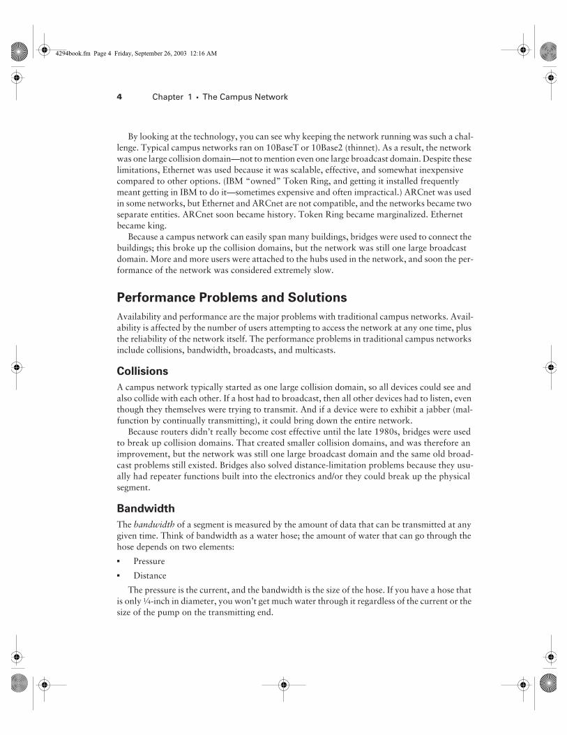
By looking at the technology, you can see why keeping the network running was such a chal-lenge. Typical campus networks ran on 10BaseT or 10Base2 (thinnet). As a result, the network was one large collision domain—not to mention even one large broadcast domain. Despite these limitations, Ethernet was used because it was scalable, effective, and somewhat inexpensive compared to other options. (IBM “owned” Token Ring, and getting it installed frequently meant getting in IBM to do it—sometimes expensive and often impractical.) ARCnet was used in some networks, but Ethernet and ARCnet are not compatible, and the networks became two separate entities. ARCnet soon became history. Token Ring became marginalized. Ethernet became king.
Because a campus network can easily span many buildings, bridges were used to connect the buildings; this broke up the collision domains, but the network was still one large broadcast domain. More and more users were attached to the hubs used in the network, and soon the per-formance of the network was considered extremely slow.
Performance Problems and Solutions
Availability and performance are the major problems with traditional campus networks. Avail-ability is affected by the number of users attempting to access the network at any one time, plus the reliability of the network itself. The performance problems in traditional campus networks include collisions, bandwidth, broadcasts, and multicasts.
Collisions
A campus network typically started as one large collision domain, so all devices could see and also collide with each other. If a host had to broadcast, then all other devices had to listen, even though they themselves were trying to transmit. And if a device were to exhibit a jabber (mal-function by continually transmitting), it could bring down the entire network.
Because routers didn’t really become cost effective until the late 1980s, bridges were used to break up collision domains. That created smaller collision domains, and was therefore an improvement, but the network was still one large broadcast domain and the same old broad-cast problems still existed. Bridges also solved distance-limitation problems because they usu-ally had repeater functions built into the electronics and/or they could break up the physical segment.
Bandwidth
The
bandwidth
of a segment is measured by the amount of data that can be transmitted at any given time. Think of bandwidth as a water hose; the amount of water that can go through the hose depends on two elements:�
Pressure�
Distance
The pressure is the current, and the bandwidth is the size of the hose. If you have a hose that is only
1
⁄
4
-inch in diameter, you won’t get much water through it regardless of the current or the size of the pump on the transmitting end.
4294book.fm Page 4 Friday, September 26, 2003 12:16 AM

Looking Back at Traditional Campus Networks
5
Another issue is distance. The longer the hose, the more the water pressure drops. You can put a repeater in the middle of the hose and re-amplify the pressure of the line, which would help, but you need to understand that all lines (and hoses) have degradation of the signal, which means that the pressure drops off the further the signal goes down the line. For the remote end to understand digital signaling, the pressure must stay at a minimum value. If it drops below this minimum value, the remote end will not be able to receive the data. In other words, the far end of the hose would just drip water instead of flow. You can’t water your crops with drips of water; you need a constant water flow.
The solution to bandwidth issues is maintaining your distance limitations and designing your network with proper segmentation of switches and routers. Congestion on a segment happens when too many devices are trying to use the same bandwidth. By properly segmenting the net-work, you can eliminate some of the bandwidth issues. You never will have enough bandwidth for your users; you’ll just have to accept that fact. However, you can always make it better.
Broadcasts and Multicasts
Remember that all protocols have broadcasts built in as a feature, but some protocols can really cause problems if not configured correctly. Some protocols that, by default, can cause problems if they are not correctly implemented are Internet Protocol (IP), Address Resolution Protocol (ARP), Network Basic Input Output System (NetBIOS), Internetwork Packet Exchange (IPX), Service Advertising Protocol (SAP), and Routing Information Protocol (RIP). However, remem-ber that there are features built into the Cisco router Internetworking Operating System (IOS) that, if correctly designed and implemented, can alleviate these problems. Packet filtering, queu-ing, and choosing the correct routing protocols are some examples of how Cisco routers can eliminate some broadcast problems.
Multicast traffic can also cause problems if not configured correctly. Multicasts are broad-casts that are destined for a specific or defined group of users. If you have large multicast groups or a bandwidth-intensive application such as Cisco’s IPTV application, multicast traffic can consume most of the network bandwidth and resources.
To solve broadcast issues, create network segmentation with bridges, routers, and switches. However, understand that you’ll move the bottleneck to the routers, which break up the broad-cast domains. Routers process each packet that is transmitted on the network, which can cause a bottleneck if an enormous amount of traffic is generated.
Understanding Broadcast Effects
Just in case anyone is still confused about broadcasts, consider this analogy. Suppose you worked in an office where there was a telephone system that included a broadcast capability. Every time the phone rang, everyone would have to answer it and listen to who the broadcast transmission was aimed at—“Hello, is that the Domain Name Server?” How long would it be before all these interruptions caused you to throw the phone out of the window? That’s what broadcasts do to PCs. Each interruption causes single-tasking operating systems to stop what they are doing—writing to the hard drive, processing, and so on—and answer the phone.
4294book.fm Page 5 Friday, September 26, 2003 12:16 AM

6
Chapter 1 �
The Campus Network
Virtual LANs (VLANs) are a solution as well, but VLANs are just broadcast domains with artificial boundaries. A VLAN is a group of devices on different network segments defined as a broadcast domain by the network administrator. The benefit of VLANs is that physical loca-tion is no longer a factor for determining the port into which you would plug a device into the network. You can plug a device into any switch port, and the network administrator gives that port a VLAN assignment. Remember that routers or layer 3 switches must be used for different VLANs to communicate.
The 80/20 Rule
The traditional campus network placed users and groups in the same physical location. If a new salesperson was hired, they had to sit in the same physical location as the other sales personnel and be connected to the same physical network segment in order to share network resources. Any deviation from this caused major headaches for the network administrators.
The rule that needed to be followed in this type of network was called the
80/20 rule
because 80 percent of the users’ traffic was supposed to remain on the local network segment and only 20 percent or less was supposed to cross the routers or bridges to the other network segments. If more than 20 percent of the traffic crossed the network segmentation devices, performance issues arose. Figure 1.1 shows a traditional 80/20 network.
F I G U R E 1 . 1
A traditional 80/20 network
172.16.10.0
172.16.20.0172.16.30.0
172.16.40.0
E0
E0
S0
S0
E2
E2
E1
E1
172.16.50.0 172.16.60.0
4294book.fm Page 6 Friday, September 26, 2003 12:16 AM

Looking Back at Traditional Campus Networks
7
Because network administrators are responsible for network design and implementation, they improved network performance in the 80/20 network by making sure that all the network resources for the users were contained within the local network segment. The resources included network servers, printers, shared directories, software programs, and applications.
The New 20/80 Rule
With new web-based applications and computing, any PC can be a subscriber or publisher at any time. Also, because businesses are pulling servers from remote locations and creating server farms (sounds like a mainframe, doesn’t it?) to centralize network services for security, reduced cost, and administration, the old 80/20 rule is obsolete and could not possibly work in this envi-ronment. All traffic must now traverse the campus backbone, which means we now have a
20/80 rule
in effect. Twenty percent of what the user performs on the network is local, whereas up to 80 percent crosses the network segmentation points to get to network services. Figure 1.2 shows the new 20/80 network.
F I G U R E 1 . 2
A 20/80 network
The problem with the 20/80 rule is not the network wiring and topology as much as it is the routers themselves. They must be able to handle an enormous number of packets quickly and efficiently at wire speed. This is probably where I should be talking about how great Cisco rout-ers are and how our networks would be nothing without them. I’ll get to that later in this chap-ter—trust me.
VLAN3
VLAN4
VLAN2
VLAN1
VLAN6VLAN5
E1
E0
S0
E2
E2
E0
E1
S0
4294book.fm Page 7 Friday, September 26, 2003 12:16 AM

8
Chapter 1 �
The Campus Network
Virtual LANs
With this new 20/80 rule, more and more users need to cross broadcast domains (VLANs), and this puts the burden on routing, or layer 3 switching. By using VLANs within the new campus model, you can control traffic patterns and control user access easier than in the traditional campus network. Virtual LANs break up broadcast domains by using either a router or a switch that can perform layer 3 functions. Figure 1.3 shows how VLANs are created and might look in an internetwork.
F I G U R E 1 . 3
VLANs break up broadcast domains in a switched internetwork.
Chapter 3, “VLANs, Trunks, and VTP,” includes detailed information about VLANs and how to configure them in an internetwork. It is imperative that you understand VLANs, because the traditional way of building the campus network is being redesigned and VLANs are a large factor in building the new campus model.
Introducing the New Campus Model
The changes in customer network requirements—in combination with the problems with col-lision, bandwidth, and broadcasts—have necessitated a new network campus design. Higher user demands and complex applications force the network designers to think more about traffic patterns instead of solving a typical isolated department issue. We can no longer just think
VLAN 1 VLAN 3
VLAN 2 VLAN 4
E0 E1
4294book.fm Page 8 Friday, September 26, 2003 12:16 AM

Introducing the New Campus Model
9
about creating subnets and putting different departments into each subnet. We need to create a network that makes everyone capable of reaching all network services easily. Server farms, where all enterprise servers are located in one physical location, really take a toll on the existing network infrastructure and make the way we used to design networks obsolete. We must pay attention to traffic patterns and how to solve bandwidth issues. This can be accomplished with higher-end routing and switching techniques.
Because of the new bandwidth-intensive applications, video and audio being delivered to the desktop, as well as more and more work being performed on the Internet, the new campus model must be able to provide the following:
Fast convergence
When a network change takes place, the network must be able to adapt very quickly to the change and keep data moving swiftly.
Deterministic paths
Users must be able to gain access to a certain area of the network with-out fail.
Deterministic failover
The network design must have provisions that make sure the network stays up and running even if a link fails.
Scalable size and throughput
As users and new devices are added to the network, the network infrastructure must be able to handle the new increase in traffic.
Centralized applications
Enterprise applications accessed by all users must be available to support all users on the internetwork.
The new 20/80 rule
Instead of 80 percent of the users’ traffic staying on the local network, 80 percent of the traffic now crosses the backbone and only 20 percent stays on the local network.
Multiprotocol support
Campus networks must support multiple protocols, both routed and routing protocols. Routed protocols are used to send user data through the internet-work (for example, IP or IPX). Routing protocols are used to send network updates between routers, which will in turn update their routing tables. Examples of routing protocols include RIP, Enhanced Interior Gateway Routing Protocol (EIGRP), and Open Shortest Path First (OSPF).
Multicasting
Multicasting is sending a broadcast to a defined subnet or group of users. Users can be placed in multicast groups, for example, for videoconferencing.
QoS
We need to be able to prioritize different traffic types.
Network Services
The new campus model provides remote services quickly and easily to all users. The users have no idea where the resources are located in the internetwork, nor should they care. There are three types of network services, which are created and defined by the administrator and should appear to the users as local services:�
Local services�
Remote services�
Enterprise services
4294book.fm Page 9 Friday, September 26, 2003 12:16 AM

10
Chapter 1 �
The Campus Network
Local Services
Local services
are network services that are located on the same subnet or network as the users accessing them. Users do not cross layer 3 devices, and the network services are in the same broadcast domain as the users. This type of traffic never crosses the backbone.
Remote Services
Remote services
are close to users but not on the same network or subnet as the users. The users would have to cross a layer 3 device to communicate with the network services. However, they might not have to cross the backbone.
Enterprise Services
Enterprise services
are defined as services that are provided to all users on the internetwork. Layer 3 switches or routers are required in this scenario because an enterprise service must be close to the core and would probably be based in its own subnet. Examples of these services include Internet access, e-mail, and possibly videoconferencing. When servers that host enter-prise services are placed close to the backbone, all users would be the same distance from the servers, but all user data would have to cross the backbone to get to the services.
Using Switching Technologies
Switching technologies are crucial to the new network design. Because the prices on layer 2 switching have been dropping dramatically, it is easier to justify the cost of buying switches for your entire network. This doesn’t mean that every business can afford switch ports for all users, but it does allow for a cost-effective upgrade solution when the time comes.
To understand switching technologies and how routers and switches work together, you must understand the Open Systems Interconnection (OSI) model. This section will give you a general overview of the OSI model and the devices that are specified at each layer.
You’ll need a basic understanding of the OSI model to fully understand discus-sions in which it is included throughout the rest of this book. For more detailed information about the OSI model, please see
CCNA: Cisco Certified Network
Associate Study Guide
, 4th edition, by Todd Lammle (Sybex, 2003).
Open Systems Interconnection (OSI) Model
As you probably already know, the
Open Systems Interconnection (OSI) model
has seven lay-ers, each of which specifies functions that enable data to be transmitted from host to host on an internetwork. Figure 1.4 shows the OSI model and the functions of each layer.
4294book.fm Page 10 Friday, September 26, 2003 12:16 AM

Using Switching Technologies
11
F I G U R E 1 . 4
The OSI model and the layer functions
The OSI model is the cornerstone for application developers to write and create networked applications that run on an internetwork. What is important to network engineers and techni-cians is the encapsulation of data as it is transmitted on a network.
Data Encapsulation
Data encapsulation
is the process by which the information in a protocol is wrapped, or con-tained, in the data section of another protocol. In the OSI reference model, each layer encapsu-lates the layer immediately above it as the data flows down the protocol stack.
The logical communication that happens at each layer of the OSI reference model doesn’t involve many physical connections, because the information each protocol needs to send is encapsulated in the layer of protocol information beneath it. This encapsulation produces a set of data called a packet (see Figure 1.5).
F I G U R E 1 . 5
Data encapsulation at each layer of the OSI reference model
Application
Presentation
Session
Transport
Network
Data Link
Physical
Segment
PDU
Packet
Frame
Bits
Upper-layer dataTCP header
DataIP header
DataLLC header
DataMAC header
0101110101001000010
Upper-layer data
FCS
FCS
4294book.fm Page 11 Friday, September 26, 2003 12:16 AM

12
Chapter 1 �
The Campus Network
Looking at Figure 1.5, you can follow the data down through the OSI reference model as it’s encapsulated at each layer. Cisco courses typically focus only on layers 2 through 4.
Each layer communicates only with its peer layer on the receiving host, and they exchange Protocol Data Units (PDUs). The PDUs are attached to the data at each layer as it traverses down the model and is read only by its peer on the receiving side. Each layer has a specific name for the PDU, as shown in Table 1.1.
Starting at the Application layer, data is converted for transmission on the network, and then encapsulated in Presentation layer information. When the Presentation layer receives this infor-mation, it looks like generic data. The Presentation layer hands the data to the Session layer, which is responsible for synchronizing the session with the destination host.
The Session layer then passes this data to the Transport layer, which transports the data from the source host to the destination host in a reliable fashion. But before this happens, the Net-work layer adds routing information to the packet. It then passes the packet on to the Data Link layer for framing and for connection to the Physical layer. The Physical layer sends the data as 1s and 0s to the destination host. Finally, when the destination host receives the 1s and 0s, the data passes back up through the model, one layer at a time. The data is de-encapsulated at each of the OSI model’s peer layers.
At a transmitting device, the data encapsulation method is as follows:
1.
User information is converted to data for transmission on the network.
2.
Data is converted to segments at the Transport layer, and any reliability parameters required are set up.
3.
Segments are converted to packets or datagrams at the Network layer, and routing infor-mation is added to the PDU.
4.
Packets or datagrams are converted to frames at the Data Link layer, and hardware addresses are used to communicate with local hosts on the network medium.
5.
Frames are converted to bits, and 1s and 0s are encoded within the digital signal.
Now that you have a sense of the OSI model and how routers and switches work together, it is time to turn our attention to the specifics of each layer of switching technology.
T A B L E 1 . 1
OSI Encapsulation
OSI Layer Name of Protocol Data Units (PDUs)
Transport Segments
Network Packets
Data Link Frames
Physical Bits
4294book.fm Page 12 Friday, September 26, 2003 12:16 AM
Using Switching Technologies 13
Layer 2 Switching
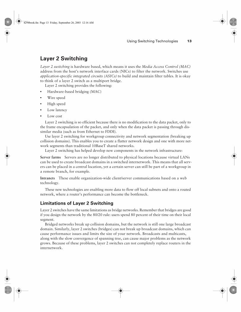
Layer 2 switching is hardware based, which means it uses the Media Access Control (MAC) address from the host’s network interface cards (NICs) to filter the network. Switches use application-specific integrated circuits (ASICs) to build and maintain filter tables. It is okay to think of a layer 2 switch as a multiport bridge.
Layer 2 switching provides the following:� Hardware-based bridging (MAC)� Wire speed� High speed� Low latency� Low cost
Layer 2 switching is so efficient because there is no modification to the data packet, only to the frame encapsulation of the packet, and only when the data packet is passing through dis-similar media (such as from Ethernet to FDDI).
Use layer 2 switching for workgroup connectivity and network segmentation (breaking up collision domains). This enables you to create a flatter network design and one with more net-work segments than traditional 10BaseT shared networks.
Layer 2 switching has helped develop new components in the network infrastructure:
Server farms Servers are no longer distributed to physical locations because virtual LANs can be used to create broadcast domains in a switched internetwork. This means that all serv-ers can be placed in a central location, yet a certain server can still be part of a workgroup in a remote branch, for example.
Intranets These enable organization-wide client/server communications based on a web technology.
These new technologies are enabling more data to flow off local subnets and onto a routed network, where a router’s performance can become the bottleneck.
Limitations of Layer 2 Switching
Layer 2 switches have the same limitations as bridge networks. Remember that bridges are good if you design the network by the 80/20 rule: users spend 80 percent of their time on their local segment.
Bridged networks break up collision domains, but the network is still one large broadcast domain. Similarly, layer 2 switches (bridges) can not break up broadcast domains, which can cause performance issues and limits the size of your network. Broadcasts and multicasts, along with the slow convergence of spanning tree, can cause major problems as the network grows. Because of these problems, layer 2 switches can not completely replace routers in the internetwork.
4294book.fm Page 13 Friday, September 26, 2003 12:16 AM

14 Chapter 1 � The Campus Network
Routing
We want to explain how routing works and how routers work in an internetwork before dis-cussing layer 3 switching next. Routers and layer 3 switches are similar in concept but not design. In this section, we’ll discuss routers and what they provide in an internetwork today.
Routers break up collision domains as bridges do. In addition, routers also break up broadcast/multicast domains.
The benefits of routing include:� Breakup of broadcast domains� Multicast control� Optimal path determination� Traffic management� Logical (layer 3) addressing� Security
Routers provide optimal path determination because the router examines each and every packet that enters an interface and improves network segmentation by forwarding data packets to only a known destination network. Routers are not interested in hosts, only networks. If a router does not know about a remote network to which a packet is destined, it will just drop the packet and not forward it. Because of this packet examination, traffic management is obtained.
The Network layer of the OSI model defines a virtual—or logical—network address. Hosts and routers use these addresses to send information from host to host within an internetwork. Every network interface must have a logical address, typically an IP address.
Security can be obtained by a router reading the packet header information and reading fil-ters defined by the network administrator (access lists).
Layer 3 Switching
The only difference between a layer 3 switch and a router is the way the administrator creates the physical implementation. Also, traditional routers use microprocessors to make forwarding decisions, and the switch performs only hardware-based packet switching. However, some tra-ditional routers can have other hardware functions as well in some of the higher-end models. Layer 3 switches can be placed anywhere in the network because they handle high-performance LAN traffic and can cost-effectively replace routers.
Layer 3 switching is all hardware-based packet forwarding, and all packet forwarding is handled by hardware ASICs. Layer 3 switches really are no different functionally from a tradi-tional router and perform the same functions, which are listed here:� Determine paths based on logical addressing� Run layer 3 checksums (on header only)� Use Time to Live (TTL)� Process and respond to any option information
4294book.fm Page 14 Friday, September 26, 2003 12:16 AM

Using Switching Technologies 15
� Can update Simple Network Management Protocol (SNMP) managers with Management Information Base (MIB) information
� Provide security
The benefits of layer 3 switching include the following:� Hardware-based packet forwarding� High-performance packet switching� High-speed scalability� Low latency� Lower per-port cost� Flow accounting� Security� Quality of service (QoS)
Layer 4 Switching
Layer 4 switching is considered a hardware-based layer 3 switching technology that can also consider the application used (for example, Telnet or FTP). Layer 4 switching provides addi-tional routing above layer 3 by using the port numbers found in the Transport-layer header to make routing decisions. These port numbers are found in Request for Comments (RFC) 1700 and reference the upper-layer protocol, program, or application.
Layer 4 information has been used to help make routing decisions for quite a while. For example, extended access lists can filter packets based on layer 4 port numbers. Another exam-ple is accounting information gathered by NetFlow switching in Cisco’s higher-end routers.
The largest benefit of layer 4 switching is that the network administrator can configure a layer 4 switch to prioritize data traffic by application, which means a QoS can be defined for each user. For example, a number of users can be defined as a Video group and be assigned more priority, or bandwidth, based on the need for videoconferencing.
However, because users can be part of many groups and run many applications, the layer 4 switches must be able to provide a huge filter table or response time would suffer. This filter table must be much larger than any layer 2 or 3 switch. A layer 2 switch might have a filter table only as large as the number of users connected to the network, maybe even smaller if some hubs are used within the switched fabric. However, a layer 4 switch might have five or six entries for each and every device connected to the network! If the layer 4 switch does not have a filter table that includes all the information, the switch will not be able to produce wire-speed results.
Multi-Layer Switching (MLS)
Multi-layer switching combines layer 2, 3, and 4 switching technologies and provides high-speed scalability with low latency. It accomplishes this combination of high-speed scalability with low latency by using huge filter tables based on the criteria designed by the network administrator.
4294book.fm Page 15 Friday, September 26, 2003 12:16 AM
16 Chapter 1 � The Campus Network
Multi-layer switching can move traffic at wire speed and also provide layer 3 routing, which can remove the bottleneck from the network routers. This technology is based on the concept of route once, switch many.
Multi-layer switching can make routing/switching decisions based on the following:� MAC source/destination address in a Data Link frame� IP source/destination address in the Network-layer header� Protocol field in the Network-layer header� Port source/destination numbers in the Transport-layer header
There is no performance difference between a layer 3 and a layer 4 switch because the rout-ing/switching is all hardware based.
MLS will be discussed in more detail in Chapter 7, “Multi-Layer Switching.”
It is important that you have an understanding of the different OSI layers and what they pro-vide before continuing on to the Cisco three-layer hierarchical model.
Understanding the Cisco Hierarchical ModelMost of us learned about hierarchy early in life. Anyone with older siblings learned what it was like to be at the bottom of the hierarchy! Regardless of where we were first exposed to hier-archy, most of us experience it in many aspects of our lives. Hierarchy helps us to understand where things belong, how things fit together, and what functions go where. It brings order and understandability to otherwise complex models. If you want a pay raise, hierarchy dictates that you ask your boss, not your subordinate. That is the person whose role it is to grant (or deny) your request.
Hierarchy has many of the same benefits in network design that it has in other areas. When used properly in network design, it makes networks more predictable. It helps us to define and expect at which levels of the hierarchy we should perform certain functions. You would ask your boss, not your subordinate, for a raise because of their respective positions in the business hierarchy. The hierarchy requires that you ask someone at a higher level than yours. Likewise, you can use tools such as access lists at certain levels in hierarchical networks and you must avoid them at others.
Let’s face it, large networks can be extremely complicated, with multiple protocols, detailed configurations, and diverse technologies. Hierarchy helps us to summarize a complex collection of details into an understandable model. Then, as specific configurations are needed, the model dictates the appropriate manner for them to be applied.
4294book.fm Page 16 Friday, September 26, 2003 12:16 AM

Understanding the Cisco Hierarchical Model 17
The Cisco hierarchical model is used to help you design a scalable, reliable, cost-effective hierarchical internetwork. Cisco defines three layers of hierarchy, as shown in Figure 1.6, each with specific functionality.
F I G U R E 1 . 6 The Cisco hierarchical model
The three layers are as follows:� Core� Distribution� Access
Each layer has specific responsibilities. Remember, however, that the three layers are logical and not necessarily physical. “Three layers” does not necessarily mean “three separate devices.” Consider the OSI model, another logical hierarchy. The seven layers describe functions but not necessarily protocols, right? Sometimes a protocol maps to more than one layer of the OSI model, and sometimes multiple protocols communicate within a single layer. In the same way, when you build physical implementations of hierarchical networks, you might have many devices in a single layer, or you might have a single device performing functions at two layers. The definition of the layers is logical, not physical.
Before we examine these layers and their functions, consider a common hierarchical design, as shown in Figure 1.7. The phrase “keep local traffic local” has almost become a cliché in the networking world. However, the underlying concept has merit. Hierarchical design lends itself perfectly to fulfilling this concept. Now, let’s take a closer look at each of the layers.
Corelayer
Distributionlayer
Accesslayer
4294book.fm Page 17 Friday, September 26, 2003 12:16 AM

18 Chapter 1 � The Campus Network
F I G U R E 1 . 7 A hierarchical network design
Core Layer
The core layer is literally the core of the network. At the top of the hierarchy, the core layer is responsible for transporting large amounts of traffic both reliably and quickly. The only pur-pose of the core layer of the network is to switch traffic as quickly as possible. The traffic trans-ported across the core is common to a majority of users. However, remember that user data is processed at the distribution layer, and the distribution layer forwards the requests to the core, if needed.
If there is a failure in the core, every single user can be affected. Therefore, fault tolerance at this layer is an issue. The core is likely to see large volumes of traffic, so speed and latency are driving concerns here. Given the function of the core, we can now look at some design specifics to consider. Let’s start with some things you know you don’t want to do:� Don’t do anything to slow down traffic. This includes using access lists, routing between
VLANs, and packet filtering.� Don’t support workgroup access here.� Avoid expanding the core when the internetwork grows (that is, adding routers). If perfor-
mance becomes an issue in the core, give preference to upgrades over expansion.
Corelayer
Distributionlayer
Accesslayer
FDDI Ring
Users’ machines Users’ machines Users’ machines
Workgroups
4294book.fm Page 18 Friday, September 26, 2003 12:16 AM

Understanding the Cisco Hierarchical Model 19
There are a few things that you want to make sure to get done as you design the core:� Design the core for high reliability. Consider Data Link technologies that facilitate both
speed and redundancy, such as FDDI, FastEthernet (with redundant links), Gigabit Ether-net, or even ATM.
� Design with speed in mind. The core should have very little latency.� Select routing protocols with lower convergence times. Fast and redundant Data Link con-
nectivity is no help if your routing tables are shot!
Distribution Layer
The distribution layer is sometimes referred to as the workgroup layer and is the communica-tion point between the access layer and the core. The primary function of the distribution layer is to provide routing, filtering, and WAN access and to determine how packets can access the core, if needed. The distribution layer must determine the fastest way that user requests are ser-viced (for example, how a file request is forwarded to a server). After the distribution layer determines the best path, it forwards the request to the core layer. The core layer is then respon-sible for quickly transporting the request to the correct service.
The distribution layer is the place to implement policies for the network. Here, you can exer-cise considerable flexibility in defining network operation. Generally, the following should be done at the distribution layer:� Implement tools such as access lists, packet filtering, and queuing.� Implement security and network policies, including address translation and firewalls.� Redistribute between routing protocols, including static routing.� Route between VLANs and other workgroup support functions.� Define broadcast and multicast domains.
Things to avoid at the distribution layer are limited to those functions that exclusively belong to one of the other layers.
Access Layer
The access layer controls user and workgroup access to internetwork resources. The access layer is sometimes referred to as the desktop layer. The network resources that most users need are available locally. Any traffic for remote services is handled by the distribution layer. The fol-lowing functions should be included at this layer:� Continued (from distribution layer) access control and policies.� Creation of separate collision domains (segmentation).� Workgroup connectivity to the distribution layer.� Technologies such as dial-on-demand routing (DDR) and Ethernet switching are frequently
seen in the access layer. Static routing (instead of dynamic routing protocols) is seen here as well.
As already noted, having three separate levels does not have to imply having three separate routers. It could be fewer, or it could be more. Remember that this is a layered approach.
4294book.fm Page 19 Friday, September 26, 2003 12:16 AM

20 Chapter 1 � The Campus Network
Using Cisco Catalyst ProductsUnderstanding the campus size and traffic is an important factor in network design. A large campus is defined as several or many colocated buildings, and a medium campus is one or more colocated buildings. Small campus networks have only one building.
By understanding your campus size, you can choose Cisco products that will fit your busi-ness needs and grow with your company. Cisco switches are produced to fit neatly within its three-layer model. This helps you decide which equipment to use for your network efficiently and quickly.
It should be noted that the Cisco range of switches is in a transitional phase between two operating systems. The Catalyst Operating System (CatOS) is the traditional method and is often referred to as using set commands because when configuring, the command often begins with the word “set.” Switches in this line include the 4000 and the 6000/6500.
The switches based on the IOS are called Catalyst IOS (CatIOS) switches. The interface to configure these switches resembles that of the IOS router but isn’t entirely the same. Anyone familiar with configuring a router, though, will be comfortable configuring one of these switches. The switches that use this include the 2950, the 3550, and the 8500 series.
With some switches—for instance, the 6000/6500 series—you have a choice between the two types of operating systems. When this occurs, the CatOS is the default OS.
Cisco Express Forwarding (CEF) allows for real layer 3 switches to forward traffic based on a complete layer 3 topology map. This map is shared with the ASICs at each port, enabling each port to know which port a packet should be forwarded to. Rather than forwarding based on MAC address, forwarding is done by layer 3 address. Only switches that have true layer 3 capa-bilities can do this type of switching. These devices include the 3550 series, the 4000 series, the 6000/6500 series with PFC2, and the 8500 series.
There are two general rules when it comes to Cisco switches: The lower model numbers usu-ally cost less, and purchasing a device with more ports drives down the per-port cost. In addi-tion, the model number may typically be split into two sections: For slot-based switches, the second number usually refers to the number of physical slots it has. The 6509 is a nine-slot device in the 6500 family of switches.
Access Layer Switches
The access layer, as you already know, is where users gain access to the internetwork. The switches deployed at this layer must be able to handle connecting individual desktop devices to the internetwork. The switches here are usually characterized as having a large number of ports and being low cost. Most access switches don’t have a lot of frills.
4294book.fm Page 20 Friday, September 26, 2003 12:16 AM

Using Cisco Catalyst Products 21
The Cisco solutions at the access layer include the following:
2950 Provides switched 10/100 Mbps to the desktop. All ports are capable of full duplex, and options include Gigabit Ethernet interfaces. The standard Cisco IOS means that the switch sup-ports functionality for basic data, video, and voice services. All Catalyst 2950 and 2955 switches also support the Cisco Cluster Management Suite (CMS) Software, which allows users to use a standard web browser to simultaneously configure and troubleshoot multiple Catalyst desktop switches.
3550 Provides a range of stackable selections that can be used as access switches with the Standard Multilayer Software Image (SMI). Many options are available, including 24 and 48 ports, inline power for IP telephony, and a range of 10/100/1000Mbps ports.
If power for IP phones is required but a switch with inline power is not avail-able, Cisco also has a product called the “Inline Power Patch Panel” that adds inline power to an existing Catalyst switch.
4000 Provides a 10/100/1000Mbps advanced high-performance enterprise solution for up to 96 users and up to 36 Gigabit Ethernet ports for servers. Some models also support the delivery of inline power for IP telephones.
Distribution Layer Switches
As discussed earlier, the primary function of the distribution layer is to provide routing, filter-ing, and WAN access and to determine how packets can access the core, if needed.
Distribution layer switches are the aggregation point for multiple access switches and must be capable of handling large amounts of traffic from these access layer devices. The distribution layer switches must also be able to participate in MLS and be able to handle a route processor.
The Cisco switches that provide these functions are as follows:
3550 Series This range includes a variety of stackable switches supporting a huge range of fea-tures. Full IOS operation complete with MLS is available, and this makes the switch suitable for both access layer and distribution layer switching.
4000 Series One of the most scalable switches, the 4000 can be used as a distribution switch if the supervisor IV engine supporting MLS is installed. The 4000 series support advanced QoS, security, and flexibility, achieved with a range of modules. Numerous chassis are available, pro-viding advanced features such as non-blocking architecture and resilience through redundant supervisors. This range has been given a real boost by Cisco.
6000 The Catalyst 6000 can provide up to 384 10/100Mbps Ethernet connections, 192 100FX FastEthernet connections, or 130 Gigabit Ethernet ports. (With the recent release of the 10/100/1000 card, the 6500 can now support up to 384 10/100/1000 Ethernet connections.) In addition to regular connections, IP telephone connections with inline power are also supported. The 6000 can be outfitted with a Multi-layer Switch Feature Card (MSFC) to provide router functionality as well as a Policy Feature Card (PFC) for layer 3 switching functionality.
4294book.fm Page 21 Friday, September 26, 2003 12:16 AM

22 Chapter 1 � The Campus Network
Core Layer Switches
The core layer must be efficient and do nothing to slow down packets as they traverse the back-bone. The following switches are recommended for use in the core:
6500 The Catalyst 6500 series switches are designed to address the need for gigabit port density, high availability, and multi-layer switching for the core layer backbone and server-aggregation environments. These switches use the Cisco IOS to utilize the high speeds of the ASICs, which allows the delivery of wire-speed traffic management services end to end.
8500 The Cisco Catalyst 8500 is a core layer switch that provides high-performance switch-ing. The Catalyst 8500 uses ASICs to provide multiple-layer protocol support including IP, IP multicast, bridging, ATM switching, and policy-enabled QoS.
All these switches provide wire-speed multicast forwarding, routing, and Protocol Indepen-dent Multicast (PIM) for scalable multicast routing. These switches are perfect for providing the high bandwidth and performance needed for a core router. The 6500 and 8500 switches can aggregate multiprotocol traffic from multiple remote wiring closets and workgroup switches.
Applying the Building BlocksRemember the saying, “Everything I need to know I learned in kindergarten”? Well, it appears to be true. Cisco has determined that following the hierarchical model they have created pro-motes a building-block approach to network design. If you did well with building blocks in your younger years, you can just apply that same technique to building large, multimillion-dollar net-works. Kind of makes you glad it’s someone else’s money you’re playing with, doesn’t it?
In all seriousness, Cisco has determined some fundamental campus elements that help you build network building blocks:
Switch blocks Access layer switches connected to the distribution layer devices.
Core blocks Support of multiple switch blocks connected together with either 4000, 6500, or 8500 switches.
Within these fundamental elements, there are three contributing variables:
Server blocks Groups of network servers on a single subnet
WAN blocks Multiple connections to an ISP or multiple ISPs
Mainframe blocks Centralized services to which the enterprise network is responsible for pro-viding complete access
By understanding how these work, you can build large, expensive networks with confidence (using someone else’s money). After the network has been built, you need to allow the switches to talk to each other to allow for redundancy and to route around outages. We will cover these topics later in this section after the blocks are discussed.
4294book.fm Page 22 Friday, September 26, 2003 12:16 AM

Applying the Building Blocks 23
Switch Block
The switch block is a combination of layer 2 switches and layer 3 routers. The layer 2 switches connect users in the wiring closet into the access layer and provide 10Mbps or 100Mbps ded-icated connections; 2950 Catalyst switches can be used in the switch block.
From here, the access layer switches connect into one or more distribution layer switches, which will be the central connection point for all switches coming from the wiring closets. The distribution layer device is either a switch with an external router or a multi-layer switch. The distribution layer switch then provides layer 3 routing functions, if needed.
The distribution layer router prevents broadcast storms that could happen on an access layer switch from propagating throughout the entire internetwork. The broadcast storm would be isolated to only the access layer switch in which the problem exists.
Switch Block Size
To understand how large a switch block can be, you must understand the traffic types and the size and number of workgroups that will be using them. The number of switches that can col-lapse from the access layer to the distribution layer depends on the following:� Traffic patterns� Routers at the distribution layer� Number of users connected to the access layer switches� Distance VLANs must traverse the network� Spanning tree domain size
If routers at the distribution layer become the bottleneck in the network (which means the CPU processing is too intensive), the switch block has grown too large. Also, if too many broad-casts or multicast traffic slow down the switches and routers, your switch blocks have grown too large.
Having a large number of users does not necessarily indicate that the switch block is too large; too much traffic going across the network does.
Core Block
If you have two or more switch blocks, the Cisco rule of thumb states that you need a core block. No routing is performed at the core, only transferring of data. It is a pass-through for the switch block, the server block, and the Internet. Figure 1.8 shows one example of a core block.
The core is responsible for transferring data to and from the switch blocks as quickly as pos-sible. You can build a fast core with a frame, packet, or cell (ATM) network technology. The Switching exam is based on an Ethernet core network.
4294book.fm Page 23 Friday, September 26, 2003 12:16 AM

24 Chapter 1 � The Campus Network
F I G U R E 1 . 8 The core block
Typically, you would have only one subnet configured on the core network. However, for redundancy and load balancing, you could have two or more subnets configured.
Switches can trunk on a certain port or ports. This means that a port on a switch can be a member of more than one VLAN at the same time. However, the distribution layer will handle the routing and trunking for VLANs, and the core is only a pass-through after the routing has been performed. Because of this, core links do not carry multiple subnets per link; the distribu-tion layer does.
A Cisco 6500 or 8500 switch is recommended at the core, and even though only one of those switches might be sufficient to handle the traffic, Cisco recommends two switches for redun-dancy and load balancing. You could consider a 4000 or 3550 Catalyst switch if you don’t need the power of the 6500 or the 8500.
Collapsed Core
A collapsed core is defined as one switch performing both core and distribution layer functions; however, the functions of the core and distribution layer are still distinct. The collapsed core is typically found in a small network.
Redundant links between the distribution layer and the access layer switches, and between each access layer switch, can support more than one VLAN. The distribution layer routing is the termination for all ports.
Figure 1.9 shows a collapsed core network design.
Switch block A Switch block B
Core Core
4294book.fm Page 24 Friday, September 26, 2003 12:16 AM

Applying the Building Blocks 25
F I G U R E 1 . 9 Collapsed core
In a collapsed core network, Spanning Tree Protocol (STP) blocks the redundant links to pre-vent loops. Hot Standby Routing Protocol (HSRP) can provide redundancy in the distribution layer routing. It can keep core connectivity if the primary routing process fails.
Dual Core
If you have more than two switch blocks and need redundant connections between the core and distribution layer, you need to create a dual core. Figure 1.10 shows an example dual-core con-figuration. Each connection would be a separate subnet.
In Figure 1.10, you can see that each switch block is redundantly connected to each of the two core blocks. The distribution layer routers already have links to each subnet in the routing tables, provided by the layer 3 routing protocols. If a failure on a core switch takes place, convergence time will not be an issue. HSRP can be used to provide quick cutover between the cores. (HSRP is covered in Chapter 9, “QoS and Redundancy.”)
Core Size
Routing protocols are the main factor in determining the size of your core. This is because rout-ers, or any layer 3 device, isolate the core. Routers send updates to other routers, and as the net-work grows, so do these updates, so it takes longer to converge or to have all the routers update. Because at least one of the routers will connect to the Internet, it’s possible that there will be more updates throughout the internetwork.
Switch block A Switch block B
Core connectivity
Coreconnectivity
4294book.fm Page 25 Friday, September 26, 2003 12:16 AM

26 Chapter 1 � The Campus Network
F I G U R E 1 . 1 0 Dual-core configuration
The routing protocol dictates the size of the distribution layer devices that can communicate with the core. Table 1.2 shows a few of the more popular routing protocols and the number of blocks each routing protocol supports. Remember that this includes all blocks, including server, mainframe, and WAN.
T A B L E 1 . 2 Blocks Supported by Routing Protocol
Routing Protocol
Maximum Number of
Peers
Number of Subnet
Links to the Core
Maximum Number
of Supported Blocks
OSPF 50 2 25
EIGRP 50 2 25
RIP 30 2 15
Switch block A Switch block B
Core block
4294book.fm Page 26 Friday, September 26, 2003 12:16 AM

Applying the Building Blocks 27
Scaling Layer 2 Backbones
Typically, layer 2 switches are in the remote closets and represent the access layer, the layer where users gain access to the internetwork. Ethernet switched networks scale well in this envi-ronment, where the layer 2 switches then connect into a larger, more robust layer 3 switch rep-resenting the distribution layer. The layer 3 device is then connected into a layer 2 device representing the core. Because routing is not necessarily recommended in a classic design model at the core, the model then looks like this:
Spanning Tree Protocol (STP)
Chapter 4, “Layer 2 Switching and the Spanning Tree Protocol (STP),” and Chapter 5, “Using Spanning Tree with VLANs,” detail the STP, but some discussion is necessary here. STP is used by layer 2 bridges to stop network loops in networks that have more than one physical link to the same network. There is a limit to the number of links in a layer 2 switched back-bone that needs to be taken into account. As you increase the number of core switches, the problem becomes that the number of links to distribution links must increase also, for redun-dancy reasons. If the core is running the Spanning Tree Protocol, then it can compromise the high-performance connectivity between switch blocks. The best design on the core is to have two switches without STP running. You can do this only by having a core without links between the core switches. This is demonstrated in Figure 1.11.
F I G U R E 1 . 1 1 Layer 2 backbone scaling without STP
Access Distribution Core
Layer 2 switch Layer 3 switch Layer 2 switch
4294book.fm Page 27 Friday, September 26, 2003 12:16 AM

28 Chapter 1 � The Campus Network
Figure 1.11 shows redundancy between the core and distribution layer without spanning tree loops. This is accomplished by not having the two core switches linked together. However, each distribution layer 3 switch has a connection to each core switch. This means that each layer 3 switch has two equal-cost paths to every other router in the campus network.
Scaling Layer 3 Backbones
As discussed in the previous section, “Scaling Layer 2 Backbones,” you’ll typically find layer 2 switches connecting to layer 3 switches, which connect to the core with the layer 2 switches. However, it is possible that some networks might have layer 2/layer 3/layer 3 designs (layer 2 connecting to layer 3 connecting to layer 3). But this is not cheap, even if you’re using someone else’s money. There is always some type of network budget, and you need to have good reason to spend the type of money needed to build layer 3 switches into the core.
There are three reasons you would implement layer 3 switches into the core:� Fast convergence� Automatic load balancing� Elimination of peering problems
Fast Convergence
If you have only layer 2 devices at the core layer, the STP will be used to stop network loops if there is more than one connection between core devices. The STP has a convergence time of more than 50 seconds, and if the network is large, this can cause an enormous number of prob-lems if it has just one link failure.
STP is not implemented in the core if you have layer 3 devices. Routing protocols, which can have a much faster convergence time than STP, are used to maintain the network.
Automatic Load-Balancing
If you provide layer 3 devices in the core, the routing protocols can load-balance with multiple equal-cost links. This is not possible with layer 3 devices only at the distribution layer, because you would have to selectively choose the root for utilizing more than one path.
Elimination of Peering Problems
Because routing is typically performed in the distribution layer devices, each distribution layer device must have “reachability” information about each of the other distribution layer devices. These layer 3 devices use routing protocols to maintain the state and reachability information about neighbor routers. This means that each distribution device becomes a peer with every other distribution layer device, and scalability becomes an issue because every device has to keep information for every other device.
If your layer 3 devices are located in the core, you can create a hierarchy, and the distribution layer devices will no longer be peers to each other’s distribution device. This is typical in an envi-ronment in which there are more than 100 switch blocks.
4294book.fm Page 28 Friday, September 26, 2003 12:16 AM

SAFE 29
SAFESAFE is Cisco’s Secure Blueprint for Enterprise Networks, the stated aim of which is to provide information on the best practice for designing and implementing secure networks. Recently, the issue of security in networking has been receiving a huge amount of attention. As part of this attention, Cisco has been at the forefront of developing this process, which is based upon the products of Cisco and its partners.
The SAFE methodology involves creating a layered approach to security, such that a failure at one layer does not compromise the whole network. Instead, it operates like a military “defense in depth.”
Defense in depth is a concept that explains how it is expected that an enemy will be able to penetrate your defensive perimeter, but that it will take time and effort. Multiple lines of defense slow down an attacker and give you more time to dis-cover and stop them. Additionally, each line of defense can have its own proce-dures, in the hope that the attacker may not be skilled in all countermeasures.
One of the main features of this new set of principles is that it defines a slightly different mod-ular concept from the original core, distribution, and access layers. That is not to say that these original layers are no longer used in design; rather, the SAFE approach is to use an alternative. In practice, designers see both methods as useful and may appropriate features from each. The basis for the new modular design concept is shown in Figure 1.12.
F I G U R E 1 . 1 2 Enterprise Composite Module
This high-level diagram shows only three blocks. Each block represents a different functional area, providing a modular understanding of the security issues. From our perspective, we need to focus in a little more on the detail, and this is expanded in the main SAFE block diagram, shown in Figure 1.13.
Figure 1.13 shows a much clearer breakout of the actual modules inside SAFE that need to be managed and secured. Each module has its own threats and protection issues. It is not expected that every network would be built using all modules, but rather that this provides a framework for understanding the security issues involved and isolating them.
From the perspective of the Cisco CCNP training program, we need to focus in again, this time looking in a little more detail at the Campus Module, as shown in Figure 1.14.
EnterpriseCampus
EnterpriseEdge
SP Edge
Frame/ATMISP AISP BPSTN
4294book.fm Page 29 Friday, September 26, 2003 12:16 AM

30 Chapter 1 � The Campus Network
F I G U R E 1 . 1 3 Enterprise SAFE block diagram
Note that the Campus Module contains a number of smaller modules, each of which is asso-ciated with a specific function.
Management Module Designed to facilitate all management within the campus network as defined by the SAFE architecture. The Management Module must be separated from the man-aged devices and areas by a firewall, by separate VLANs, and by separate IP addresses and sub-net allocation.
Building Module SAFE defines the Building Module as the part of the network that contains end-user workstations and devices plus the layer 2 access points. Included in this are the Build-ing Distribution Module and Building Access Module.
Building Distribution Module This module provides standard distribution-layer services to the building switches, including routing, access control, and, more recently, QoS (quality of service) support.
Management
Building
BuildingDistribution
EdgeDistribution
E-Commerce ISPB
ServerCorporateInternet
ISPA
VPN &RemoteAccess
PSTN
WAN Frame/ATM
Core
Enterprise Campus Enterprise Edge SP Edge
4294book.fm Page 30 Friday, September 26, 2003 12:16 AM

SAFE 31
Building Access Module The Building Access Module defines the devices at the access layer, including Layer 2 switches, user workstations and, more recently, IP telephones.
Core Module This module follows the principles of the core part of the standard Cisco three-layer module, focusing on transporting large amounts of traffic both reliably and quickly.
Server Module The main goal of the Server Module is to provide access to the application ser-vices by end users and devices.
F I G U R E 1 . 1 4 Enterprise Campus Module detailed diagram
Management Module Building Access Module
OTPServer
AccessControlServer
NetworkMonitoring
IDSDirectory
Syslog 1
Syslog 2
SystemAdmin
M
ServerModule
InternalE-mail
DepartmentServer
CorporateServer
CiscoCall Manager
TermServer(IOS)
BuildingDistribution
Module
Core Module
BuildingDistribution
Module
ToE-Commerce
Module
To CorporateInternetModule
ToVPN/Remote
AccessModule
To WANModule
4294book.fm Page 31 Friday, September 26, 2003 12:16 AM

32 Chapter 1 � The Campus Network
SummaryCisco Systems manufactures a large, varied, and ever-changing range of equipment. Over the years, the acquisition of a number of companies producing switches has meant that the range has not always appeared entirely consistent, but as time marches on, some of the differences in the underlying basics of the equipment are beginning to disappear. The most obvious differences in switch models now comes down to two factors: Are the switches modular (4000, 6500) or fixed footprint (2950, 3550), and do they support just layer 2 (2950) or can you buy a layer 3 capability (4000, 6500, 3550)?
Of course, the next question that arises is “Which switch should I choose?” Naturally there are issues of cost and size (in terms of ports and so on), but that may not be sufficient to help you design a complex network. So Cisco has pioneered some design guidelines that will help you put a specific Cisco box into a “location” in your internetwork, dependent upon the technolo-gies required at that network point.
In order to understand all of this, there are two specific areas that we had to focus on. This first was how Cisco defines the network design model, in terms of redundancy, QoS, through-put, security, and so on, and how the Cisco models explain that to us. Cisco uses a three-layer model in which the access layer is used to provide redundant access to end users, the distribution layer manages policy, and the core layer provides fast access to the network backbone. Cisco also has a second model, related to its Secure Blueprint for Enterprise Networks (SAFE) guide-lines, called the Enterprise Composite Module, which allows easy identification of modules such as the Management, Campus, Enterprise Edge, and SP Edge modules.
The second area we focused on was what technologies are available. Switches have tradi-tionally been layer 2 devices, operating by forwarding data using MAC address tables. This is fast, but not very scalable, which means that routers, operating at layer 3, have been used. Mod-ern devices can commonly combine the switching and routing processes, resulting in layer 3 switching. Layer 4 switching is an extension of that process, using the port fields inside TCP and UDP to assist with forwarding decisions. The total effect is commonly referred to as Multi-Layer Switching—MLS.
Exam EssentialsUnderstand the concept behind the three-layer model. In order to provide some framework to the design process, Cisco has designed the three-layer model, with the built-in principles that functionality can be assigned to a specific layer. This allows easier equipment selection and con-figuration, as long as you remember which layer does what! The access layer is used to provide access for most users into the rest of the network. The distribution layer is used for routing, fil-tering, and for some access tasks. Finally, the core layer is used to link switch blocks, and noth-ing that slows traffic down should be run here.
Understand the reasoning behind each of the switch block types. A switch block is a col-lection of switching devices that provide access and distribution layer functions. Each of the block models has specific needs, and the Cisco range of equipment is designed to carry out the
4294book.fm Page 32 Friday, September 26, 2003 12:16 AM

Key Terms 33
appropriate tasks. The result is that different switches perform optimally at different layers. Servers may benefit from duplex connectivity and larger bandwidth than clients, due to the aggregated traffic, and because SAFE planning demands that the network be protected in depth, blocks must be clearly defined.
Understand the different product lines and the individual products that Cisco has available for switching tasks. Some Cisco devices are standard layer 2 switches, and use just the MAC address for forwarding. This is simple, cheap, and pretty fast. But the limits of scalability mean that such devices can not be used throughout the network, so Cisco also manufactures switches that provide real layer 3 services. Understanding the needs of different layers assists with the selection of the correct switch and the planning of the appropriate configuration, which might be simple layer 2 switching, or possibly MLS.
Key TermsBefore you take the exam, be sure you’re familiar with the following terms:
20/80 rule enterprise services
80/20 rule hierarchy
access layer layer 2 switching
application-specific integratedcircuits (ASICs)
layer 3 switching
bandwidth layer 4 switching
Cisco hierarchical model layered
collapsed core local services
core block Media Access Control (MAC)
core layer multi-layer switching
data encapsulation Open Systems Interconnection (OSI) model
distribution layer remote services
switch block
4294book.fm Page 33 Friday, September 26, 2003 12:16 AM

34 Chapter 1 � The Campus Network
Written LabsIn this section, you will complete the following written labs:� Lab 1.1: Switching Definitions� Lab 1.2: Cisco’s Three-Layer Model� Lab 1.3: Switching Theory
Lab 1.1: Switching Definitions
In the following table, the first column contains definitions of different types of switching. Fill in the second column with the number or numbers of the correct switching technology.
1. Layer 2 switching
2. Layer 3 switching
3. Layer 4 switching
4. Multi-layer switching
Definition Switching Type
Based on “route once, switch many”
Enables prioritization based on specific applications
Creates security by using source or destination addresses and port numbers
Can use NetFlow switching
Enables you to create flatter networks
Builds a filtering table based on application port numbers
Communicates with peer layers in a different system with packets
Reads the TCP and UDP port fields for filtering and forwarding information
Uses access lists to control traffic
Uses hardware-based routing
Uses hardware-based bridging
Uses an ASIC to handle frame forwarding
Provides both layer 2 and layer 3 functions
4294book.fm Page 34 Friday, September 26, 2003 12:16 AM

Written Labs 35
Lab 1.2: Cisco’s Three-Layer Model
Options 1, 2, and 3 are the layers in the Cisco three-layer model. Match the functions to the cor-rect layer.
1. Access layer
2. Distribution layer
3. Core layer
Lab 1.3: Switching Theory
Write the answers to the following questions:
1. Which device is used to break up broadcast domains?
2. Which device is used to break up collision domains?
3. What are the units of data at the lowest four layers of the OSI model, in top-to-bottom order?
4. Which Cisco layer is used to pass traffic as quickly as possible?
5. What is the Protocol Data Unit (PDU) used at the Transport layer?
6. What is the PDU used at the Network layer?
7. Which Cisco layer is used to break up collision domains?
8. Which OSI layer creates frames by encapsulating packets with a header and trailer?
9. What devices provide multicast control and packet-based security?
10. What breaks up broadcast domains in a layer 2 switched network?
Function Layer
Routes traffic between VLANs
Uses collision domains
Uses broadcast domains
Uses access lists
Provides end users with access to the network
Communicates between the switch blocks and to the enterprise servers
Switches traffic as quickly as possible
4294book.fm Page 35 Friday, September 26, 2003 12:16 AM

36 Chapter 1 � The Campus Network
Review Questions1. You work for a large company that needs to connect four buildings with a high-speed, high-
bandwidth backbone. They are all on the same city block, and fiber already connects the build-ings. There are multiple departments in each building and all run multiple protocols. The com-pany already owns Cisco Catalyst 6000 series switches, which you can use for the distribution layer. What switch should you use for the core layer?
A. 2950
B. 4000
C. 6500
D. 8500
2. You need to install a large switched network for a company that has already defined its business requirements to be gigabit-speed data transfer, high availability, and ISL routing to the server farms for all 300 users. What switch would you install for the distribution layer?
A. 2950 with gigabit uplinks
B. 4000 series
C. 3550 series
D. 6000 series with a 16-port gigabit module
E. 8500 series with gigabit uplinks
3. You just have been hired as a consultant for a small company that has users distributed across many floors in the same building. Servers for the company are all located on the first floor, and 30 users access them from various parts of the building. What switch would you install for the access layer connection?
A. 2950
B. 3550 series
C. 6000
D. 8000
4. You have just been promoted to network manager (congratulations!) for a large company. You need to connect four switch blocks; each contains 1500 users. You want to control broadcast domains at the switch blocks and use ISL to trunk between them. What switch would you pur-chase for the distribution layer?
A. 2950 with gigabit links
B. 3550 series
C. 4000 with gigabit VLAN
D. Catalyst 6000 with 16-port gigabit module
4294book.fm Page 36 Friday, September 26, 2003 12:16 AM

Review Questions 37
5. Which layer must be efficient and do nothing to slow down packets as they traverse the backbone?
A. Access
B. Distribute
C. Distribution
D. Backbone
E. Core
6. Which of the following switches are recommended for use in the core? (Choose all that apply.)
A. 3550 series
B. 4000 series
C. 6500
D. 8500
7. Which of the following is the main factor in determining the size of your core?
A. Routing protocols
B. Routed protocols
C. IP broadcasts
D. ARPs
E. ICMP redirects
F. Number of distribution layer switches
8. The number of switches that can collapse from the access layer to the distribution layer depends on what? (Choose all that apply.)
A. Traffic patterns
B. Routers at the distribution layer
C. Number of users connecting to the core layer
D. Number of users connected to the access layer switches
E. Number of distribution layer switches
F. Distance VLANs must traverse the network
G. Spanning tree domain size
9. Which of the following is generally performed at the distribution layer? (Choose all that apply.)
A. Breaking up of collision domains
B. No packet filtering
C. Access lists, packet filtering, and queuing
D. Routing between VLANs
4294book.fm Page 37 Friday, September 26, 2003 12:16 AM

38 Chapter 1 � The Campus Network
10. Which of the following is also generally performed at the distribution layer? (Choose all that apply.)
A. Broadcast and multicast domain definition
B. Security and network policies
C. Redistribution between routing protocols
D. User access to the network
11. Which of the following is true regarding the access layer? (Choose all that apply.)
A. This is where users gain access to the internetwork.
B. The switches deployed at this layer must be able to handle connecting individual desk-top devices to the internetwork.
C. It is the aggregation point for multiple access switches.
D. It can participate in MLS and handle a router processor.
12. Which of the following series of switches are suggested for use at the access layer? (Choose all that apply.)
A. 2950
B. 3550 series
C. 4000 series
D. 6000
E. 8000
13. Which of the following Cisco switches provides a 10/100/1000Mbps advanced high-performance enterprise solution for up to 96 users and up to 36 Gigabit Ethernet ports for servers?
A. 2950
B. 3550 series
C. 4000 series
D. 6000
E. 8000
14. Which of the following switches runs IOS by default? (Choose all that apply.)
A. 2950
B. 3550 series
C. 4000 series
D. 6000
4294book.fm Page 38 Friday, September 26, 2003 12:16 AM

Review Questions 39
15. Which of the following switches provides switched 10Mbps to the desktop or to 10BaseT hubs in small-to-medium campus networks?
A. 2950
B. 3550 series
C. 4000 series
D. 6000
16. Which layer of switching makes no modification of the data packet?
A. Layer 2
B. Layer 3
C. Layer 4
D. MLS
17. Layer 2 switching is ___________________. (Choose all that apply.)
A. Software based
B. Hardware based
C. Wire speed
D. Asymmetrical
E. Filtered using ASICs
18. Which Cisco switch can provide up to 384 10/100Mbps Ethernet connections, 192 100FX FastEthernet connections, or 130 Gigabit Ethernet ports?
A. 2950
B. 3550 series
C. 4000 series
D. 6000
19. Which of the following describes Cisco Catalyst 3550 series switches?
A. They provide an enterprise solution for up to 96 users and up to 36 Gigabit Ethernet ports for servers.
B. They run IOS in a mid-range switch with internal routing capability.
C. They only use an external router processor such as a 4000 or 7000 series router.
D. The 3550 series is the Catalyst low-end model.
20. Which of the following is true regarding the distribution layer switches? (Choose all that apply.)
A. The distribution layer is the aggregation point for multiple access switches.
B. This is where users gain access to the internetwork.
C. The switches deployed at this layer must be able to handle connecting individual desk-top devices to the internetwork.
D. The distribution layer can participate in MLS and handle a router processor.
4294book.fm Page 39 Friday, September 26, 2003 12:16 AM

40 Chapter 1 � The Campus Network
Answers to Written Labs
Answers to Lab 1.1
Answers to Lab 1.2
Definition Numbered Answer
Based on “route once, switch many” 4
Enables prioritization based on specific applications 3
Creates security by using source or destination addresses and port numbers 3
Can use NetFlow switching 2, 3
Enables you to create flatter networks 1
Builds a filtering table based on application port numbers 3
Communicates with peer layers in a different system with packets 2
Reads the TCP and UDP port fields for filtering and forwarding information 3
Uses access lists to control traffic 2, 3
Uses hardware-based routing 2
Uses hardware-based bridging 1
Uses an ASIC to handle frame forwarding 1, 2
Provides both layer 2 and layer 3 functions 4
Function Layer
Routes traffic between VLANs 2
Uses collision domains 1
Uses broadcast domains 2
Uses access lists 2
Provides end users with access to the network 1
Communicates between the switch blocks and to the enterprise servers 3
Switches traffic as quickly as possible 3
4294book.fm Page 40 Friday, September 26, 2003 12:16 AM

Answers to Written Labs 41
Answers to Lab 1.3
1. A layer 3 device, usually a router. Layer 2 devices do not break up broadcast domains.
2. A layer 2 device, typically a switch. Although routers break up both collision domains and broadcast domains, layer 2 switches are primarily used to break up collision domains.
3. Segment, packet, frame, bits. It is important to understand the question. This question asked for the units of data, which shows how data is encapsulated as user data goes from the Application layer down to the Physical layer.
4. The core layer should have no packet manipulation, if possible.
5. Segments are the name for the PDU used at the Transport layer.
6. A packet or datagram is the PDU used at the Network layer.
7. Access layer. Remember, the distribution layer is used to break up broadcast domains, and the access layer is used to break up collision domains.
8. Data Link. Data is encapsulated with header and trailer information at the Data Link layer.
9. Routers or layer 3 devices are the only devices that control broadcasts and multicasts, as well as providing packet filtering.
10. Virtual LANs. These are configured on the layer 2 switches, and layer 3 devices provide a means for moving traffic between the VLANs.
4294book.fm Page 41 Friday, September 26, 2003 12:16 AM

42 Chapter 1 � The Campus Network
Answers to Review Questions1. D. A Cisco 6500 or 8500 switch is recommended at the core, and even though only one of those
switches might be sufficient to handle the traffic, Cisco recommends two switches for redun-dancy and load balancing. You could consider a 4000 or a 3550 Catalyst switch if you don’t need the power of the 6500 or the 8500. Because the customer is using 6500 at the distribution layer, you should use 8500s as the core switches. D is the best answer.
2. C. The Catalyst 6000 can provide up to 384 10/100Mbps Ethernet connections, 192 100FX FastEthernet connections, or 130 Gigabit Ethernet ports. Because there are 300 users, the 6000 series would be a good fit. The 8500 is a recommended core switch, and the question asks for an access layer/distribution layer solution.
3. A. A 3550 series switch might be overkill for the needs of the company. Because the question involves a small company and no growth was specified, a couple of 2950s would be the most cost-effective solution.
4. B. In this instance, the 3550 series have a number of switches capable of supporting the required layer 3 services.
5. E. The core layer should be designed to connect distribution layer devices. No packet manipu-lation should occur at this layer.
6. C, D. The core layer needs very fast switches to move data as quickly as possible between dis-tribution layer devices.
7. A. Routing protocols are protocols that are used to update routers with network information. Routed protocols are used to send user data through an internetwork.
8. A, B, D, F, G. Traffic patterns, the number of routers, the number of users connected into access layer switches, distance, and spanning tree size are all factors that contribute to the number of switches that can collapse from the access layer to the distribution layer.
9. C, D. The distribution layer performs routing, which breaks up broadcast domains. Routers can be configured with access lists, packet filters, and queuing.
10. A, B, C. The distribution layer performs routing, which breaks up broadcast domains by default. Security can be performed as well as network policies implemented. Routing protocols can be redistributed with most Cisco routers.
11. A, B. The access layer breaks up collision domains and connects the access layer to the internet-work by connecting to the distribution layer.
12. A, B, C. Any switches from the 2950 series to the 4000 series can work at the access layer.
13. C. The Cisco 4000 series was created for high performance, up to 36 gigabit ports, and 96-user connectivity.
14. A, B. Both the 2950 and the 3550 runs IOS. The 4000 and 6000 can be upgraded from the default CatOS.
4294book.fm Page 42 Friday, September 26, 2003 12:16 AM

Answers to Review Questions 43
15. A. The 2950 is the current entry model that provides 10Mbps switched networking with up to 24 ports.
16. A. The Data Link layer (layer 2) encapsulates the packet but does not make any changes to it.
17. B, C, E. Layer 2 switching is considered hardware based because it uses an ASIC chip to make filtering decisions. It is also considered wire speed because no modification to the data packet takes place.
18. D. The Cisco Catalyst 6000 series provides up to 384 10/100Mbps Ethernet ports for user con-nectivity. It can also provide 192 100Mbps FastEthernet fiber uplinks or 130 Gigabit Ethernet ports.
19. B. The 3550 series Catalyst switches are the new kid on the block. With a range of different interface options from 10Mbps to gigabit speeds, they run IOS and perform full MLS internally.
20. A, D. The distribution layer connects the access layer devices, performs routing, and can provide multi-layer switching.
4294book.fm Page 43 Friday, September 26, 2003 12:16 AM

4294book.fm Page 44 Friday, September 26, 2003 12:16 AM