Chapter Tests and Problems - · PDF fileChapter Tests and Problems ... with sheet metal parts...
13
Copyright © 2017 Cengage Learning® . All Rights Reserved. May not be scanned, copied, or duplicated, or posted to a publicly accessible website, in whole or in part. Chapter Tests and Problems CHAPTER 19 PRECISION SHEET METAL DRAFTING TEST INSTRUCTIONS Answer the questions with short, complete statements or draw- ings as needed. QUESTIONS 1. Briefly discuss how the term precision sheet metal drafting is used in this chapter is different from the term associated with sheet metal parts used in construction applications. 2. What specific material does the term sheet metal represent? 3. Describe how plate material is different from sheet metal. 4. Describe sheet metal parts. 5. Define flat pattern. 6. How can phantom line be used to represent a flat pattern on a drawing? 7. Describe a drawing showing only the flat pattern using rect- angular coordinate dimensioning without dimension lines and tabular feature. 8. Describe the following precision sheet metal applications: tables, the use of a hole table, bend table, and a drawing showing a flat pattern with manufacturing information ex- tracted to a table. 9. Give an example of bend instructions that mean bend up 908 with a .120 bend radius. 10. Define the bend tangent line and describe how it is drawn. 11. Define the centerline of bend and describe how it is drawn. 12. Describe how the inside mold line is drawn. 13. Describe how the outside mold line is drawn. 14. Define bend allowance. 15. What is the purpose of a bend allowance calculation? 16. Define neutral axis. 17. Typically, where is the neutral axis? 18. Define the K-factor. 19. Describe bend transition. 20. What are bend facets and when are they used? 21. Give the purpose of bend relief. 22. How is corner relief used? 23. Define flange. 24. Describe the characteristics of a typical miter joint. 25. Define seam. 26. Define hem. 27. When are hems necessary? 28. What is a roll form? 29. When is a roll form used? 30. Define lancing. 31. Define blanking. 32. What is a stamping press? 33. Describe nesting blanks. 34. Name the three dimensioning practices that are commonly used for precision sheet metal drafting applications. 35. Describe undimensioned drawings. 36. Give the basic function of grid lines. 37. Describe dimensional accuracy points. 38. How are registration marks used in the place of grid lines? 39. How many registration marks are used and what is their orientation? 40. Show the media note that should be placed on all undimen- sioned drawings. CHAPTER 19 PRECISION SHEET METAL DRAFTING PROBLEMS INSTRUCTIONS 1. From the given sketch, draw the required views. 2. Include all dimensions needed using the specified dimen- sioning system and correct ASME dimensioning standards. 3. Use an appropriate sheet size, border, and ASME standard sheet blocks. 4. Include the following general notes at the lower-left corner of the sheet .5 in. each way from the corner border lines: 59728_ch19_EOC_ptg01.indd 1 03/02/16 10:35 am
Transcript of Chapter Tests and Problems - · PDF fileChapter Tests and Problems ... with sheet metal parts...

Copyright © 2017 Cengage Learning®. All Rights Reserved. May not be scanned, copied, or duplicated, or posted to a publicly accessible website, in whole or in part.
Chapter Tests and Problems
ChaPTer 19 PreCision sheeT MeTal DrafTing TesT
INSTRUCTIONS
Answer the questions with short, complete statements or draw-ings as needed.
QUESTIONS
1. Briefly discuss how the term precision sheet metal drafting is used in this chapter is different from the term associated with sheet metal parts used in construction applications.
2. What specific material does the term sheet metal represent?3. Describe how plate material is different from sheet metal.4. Describe sheet metal parts.5. Define flat pattern.6. How can phantom line be used to represent a flat pattern on
a drawing?7. Describe a drawing showing only the flat pattern using rect-
angular coordinate dimensioning without dimension lines and tabular feature.
8. Describe the following precision sheet metal applications: tables, the use of a hole table, bend table, and a drawing showing a flat pattern with manufacturing information ex-tracted to a table.
9. Give an example of bend instructions that mean bend up 908 with a .120 bend radius.
10. Define the bend tangent line and describe how it is drawn.11. Define the centerline of bend and describe how it is drawn.12. Describe how the inside mold line is drawn.13. Describe how the outside mold line is drawn.14. Define bend allowance.15. What is the purpose of a bend allowance calculation?16. Define neutral axis.17. Typically, where is the neutral axis?18. Define the K-factor.19. Describe bend transition.
20. What are bend facets and when are they used?21. Give the purpose of bend relief.22. How is corner relief used?23. Define flange.24. Describe the characteristics of a typical miter joint.25. Define seam.26. Define hem.27. When are hems necessary?28. What is a roll form?29. When is a roll form used?30. Define lancing.31. Define blanking.32. What is a stamping press?33. Describe nesting blanks.34. Name the three dimensioning practices that are commonly
used for precision sheet metal drafting applications.35. Describe undimensioned drawings.36. Give the basic function of grid lines.37. Describe dimensional accuracy points.38. How are registration marks used in the place of grid lines?39. How many registration marks are used and what is their
orientation?40. Show the media note that should be placed on all undimen-
sioned drawings.
ChaPTer 19 PreCision sheeT MeTal DrafTing ProbleMs
INSTRUCTIONS
1. From the given sketch, draw the required views.
2. Include all dimensions needed using the specified dimen-sioning system and correct ASME dimensioning standards.
3. Use an appropriate sheet size, border, and ASME standard sheet blocks.
4. Include the following general notes at the lower-left corner of the sheet .5 in. each way from the corner border lines:
59728_ch19_EOC_ptg01.indd 1 03/02/16 10:35 am

Copyright © 2017 Cengage Learning®. All Rights Reserved. May not be scanned, copied, or duplicated, or posted to a publicly accessible website, in whole or in part.
NOTES:1. DIMENSIoNING AND TolErANcING pEr ASME y14.5-2009.2. rEMovE All BUrrS AND SHArp EDGES.
Additional general notes can be required, depending on the specifications of each individual assignment. Use the following for tolerances for unspecified inch values. A tolerance block is recommended as described in chapter 2.
Unspecified Tolerances
Decimals in.
X 6.1
XX 6.01
XXX 6.005
ANGULAR 6309
FINISH 125 µin.
For metric drawings, provide a general note that states TolEr-ANcES For UNSpEcIFIED DIMENSIoNS coMply WITH ISo 2768-m. provide a general note that states SUrFAcE FINISH 3.2 µm UNlESS oTHErWISE SpEcIFIED.
(00.000)
(00.
000)
(.81
2)
(5.8
12)
(6.6
25)
(1.875)
(3.500)
(5.125)(UP 908 @ .250 R)
(UP 908 @ .250 R)
(7.000)
2X Ø(.406)
FLAT PATTERN(SCALE .50X)
SIDE OFTANK REF
2X Ø .416.396
2X.281.218 Ø .030 A
AB
C
B C R
6.6566.593
5.000
3.5313.468
.843
.812
1.750
2.0311.968
PRECISION SHEET METAL DETAIL DRAWINGS
Part 1: Problems 19.1 Through 19.12
PROBLEM 19.1 Drawing displayed in form view and flat pattern (in.)
part Name: Mounting Bracket
Material: .23 THK 5086-H32
Courtesy TEMCO
Drafting templates
To access CADD template files with predefined drafting settings, go to the Student Companion Website, select Student Downloads and Drafting Templates, and then select the appropriate template file.
59728_ch19_EOC_ptg01.indd 2 03/02/16 10:35 am

Copyright © 2017 Cengage Learning®. All Rights Reserved. May not be scanned, copied, or duplicated, or posted to a publicly accessible website, in whole or in part.
(00.000)
(00.
000)
(.43
7)
(1.0
62)
(1.5
00)
(1.000)
(1.125)
(1.750)
(2.750)
1.062
.437
.625
1.250
.031[
1.7811.718
1.031.968
2X .312.250 [ 2X (.281)[
1.5311.468
UP 908 @ SHARP R
B
A
A B
PROBLEM 19.2 Drawing displayed in form view and flat pattern (in.)
part Name: Bracket
Material: 14 GA GAlv crS
Courtesy TEMCO
59728_ch19_EOC_ptg01.indd 3 03/02/16 10:35 am

Copyright © 2017 Cengage Learning®. All Rights Reserved. May not be scanned, copied, or duplicated, or posted to a publicly accessible website, in whole or in part.
PROBLEM 19.3 Chassis layout (in.)
part Name: chassis
Material: Aluminum
Given: The engineer’s rough sketch of a computer component chassis.
Do the following using correct ASME standards:
1. Make a flat pattern drawing of the given chassis on properly sized sheet. Full scale is recommended.
2. Use arrowless tabular dimensioning from the given datums.
59728_ch19_EOC_ptg01.indd 4 03/02/16 10:35 am

Copyright © 2017 Cengage Learning®. All Rights Reserved. May not be scanned, copied, or duplicated, or posted to a publicly accessible website, in whole or in part.
000 000.250 .250
1.750 2.00
5.031
8.00
10.125
AAC
DC
000.500.625
5.875
.125 THK
10.2
50
000 .5
00 3.12
5 7.12
5
8.75
0
10.6
2512
.625
14.0
00
2.50
4.8756.5007.125
3.25
4.375
2X R
.250.500
.125.250
DETAIL D
BEND RADIUS = .062
A
A
A
AA
AB
B
908
PROBLEM 19.4 Chassis layoutGiven: The engineer’s rough sketch of a computer component chassis.
Do the following:
1. Make a flat pattern drawing of the given chassis on a properly sized sheet. Full scale is recommended. Establish the flat pattern layout dimension by bend allowance calculations. Show all math formulas and calculations on another paper.
2. Use arrowless tabular dimensioning from the given datums.
Dimensioning Table
hole symbol hole Diameter Depth Quantity
A .123 Through 9
B .230 Through 2
C .469 .030 2
D See detail D Through 1
3. Standard dimensioning is needed for the total length of flat pattern and a dimension from one datum to the bend line in the flat pattern.
PROBLEM 19.5 Display of part in form view with flat pat-tern shown as phantom line (in.)
part Name: Formed plate
Material: Hc-112 6 mm THK
Problem based on original art courtesy Hyster Company.
59728_ch19_EOC_ptg01.indd 5 03/02/16 10:35 am

Copyright © 2017 Cengage Learning®. All Rights Reserved. May not be scanned, copied, or duplicated, or posted to a publicly accessible website, in whole or in part.
PROBLEM 19.6 Display of part in form view and in flat pattern (in.)Given the following engineer’s layout, draw the flat pattern and the formed view. Use geometric dimensioning and tolerancing as shown.
part Name: Mounting Bracket
Material: 11 GA A569
Courtesy TEMCO
FLAT PATTERN
FORM VIEW
(3.546)
1.125
.562
1.6632X
(1.882)
2X (2.015)
2.250
(5.211)
2X R .281.218
R
2X .125
.075
2X .448.436
.572
.562 ¥
2X R.218.156
10X R .156.093
2X (1.812)
9.0318.968
1.2811.218
UP
908
@ .1
87R
UP
908
@.1
87R
2X R8.8768.814
1.656
2.0311.968
3.5933.531
7.1257.062
X
59728_ch19_EOC_ptg01.indd 6 03/02/16 10:35 am

Copyright © 2017 Cengage Learning®. All Rights Reserved. May not be scanned, copied, or duplicated, or posted to a publicly accessible website, in whole or in part.
1.891
3.783
2.641
5.283
R.5004X Ø1.0152X Ø.280
.750
1.500
DOWN 180° R.525CLB
SEE FOLDED VIEW
(R.525)BEND
(1.050)
PROBLEM 19.7 Display of 3-D part model, part in form view and with flat pattern (in.)
part Name: U-Strap
Material: 14 GA ASTM A366
Draw the 3-D model, formed views, and flat pattern using unidirectional dimensioning.
59728_ch19_EOC_ptg01.indd 7 03/02/16 10:35 am

Copyright © 2017 Cengage Learning®. All Rights Reserved. May not be scanned, copied, or duplicated, or posted to a publicly accessible website, in whole or in part.
PROBLEM 19.8 Flat pattern (in.)
part Name: Bracket
Material: 11-gauge (.1196 in.) SAE 1040 steel
The bend radius is equal to the thickness of the material.
Draw the flat pattern using unidirectional dimensioning.
59728_ch19_EOC_ptg01.indd 8 03/02/16 10:35 am
Copyright © 2017 Cengage Learning®. All Rights Reserved. May not be scanned, copied, or duplicated, or posted to a publicly accessible website, in whole or in part.
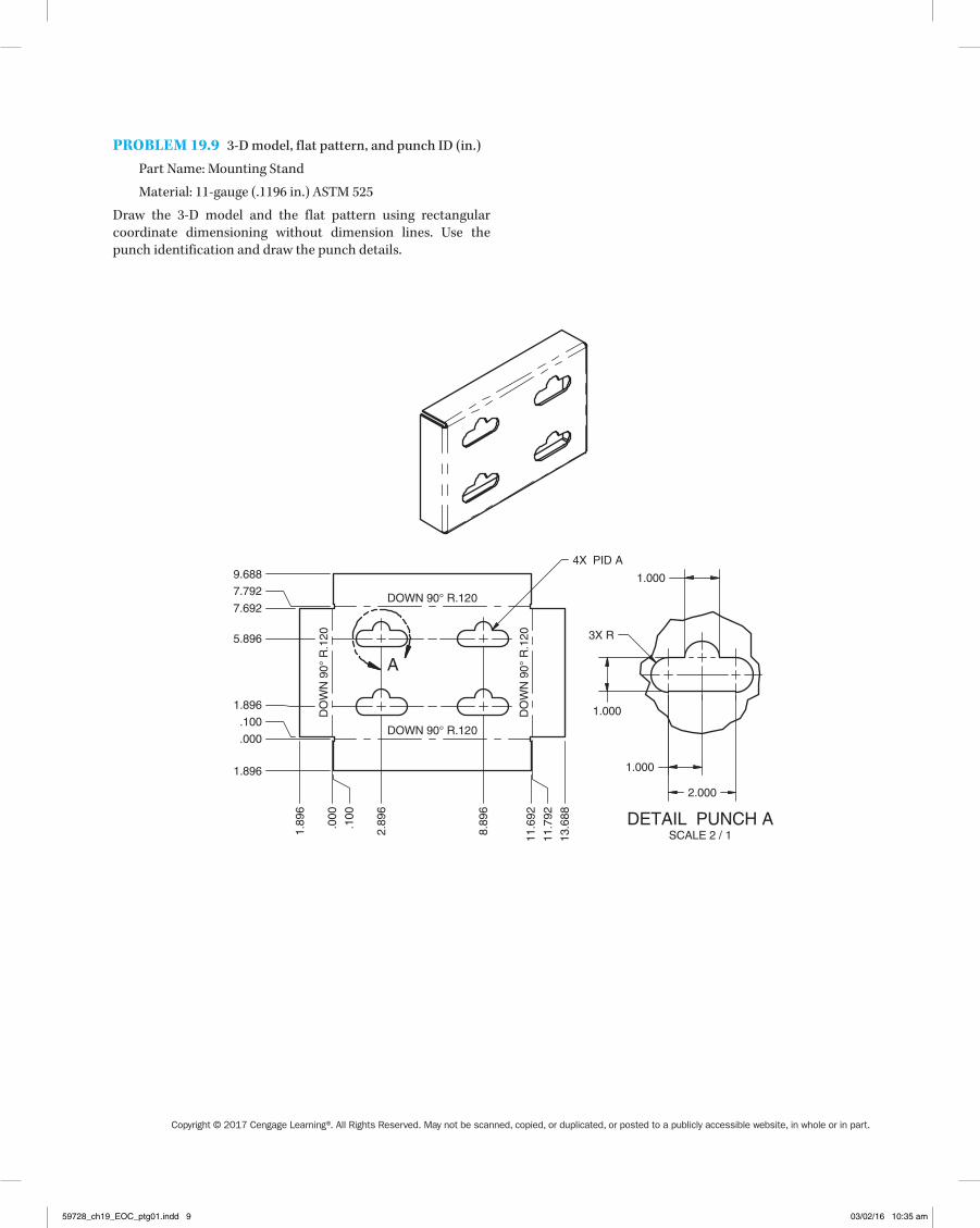
PROBLEM 19.9 3-D model, flat pattern, and punch ID (in.)
part Name: Mounting Stand
Material: 11-gauge (.1196 in.) ASTM 525
Draw the 3-D model and the flat pattern using rectangular coordinate dimensioning without dimension lines. Use the punch identification and draw the punch details.
DETAIL PUNCH ASCALE 2 / 1
A
DO
WN
90°
R.1
20
DOWN 90° R.120
DO
WN
90°
R.1
20
4X PID A
DOWN 90° R.120
.000
1.89
6
.100
2.89
6
8.89
6
11.6
92
11.7
92
13.6
88
.000
1.896
.100
1.896
5.896
7.692
7.792
9.688
1.000
3X R
1.000
1.000
2.000
59728_ch19_EOC_ptg01.indd 9 03/02/16 10:35 am

Copyright © 2017 Cengage Learning®. All Rights Reserved. May not be scanned, copied, or duplicated, or posted to a publicly accessible website, in whole or in part.
PROBLEM 19.10 3-D model, flat pattern, and punch ID (in.)
part Name: Support Bracket
Material: 11-gauge (.1196 in.) ASTM 304
Draw the 3-D model and the flat pattern using rectangular coordinate dimensioning without dimension lines. Use the punch identification and draw the punch details.
.000
.380
.500
.750
1.500
2.250
2.500
2.620
3.000
.000
.625
1.32
1
1.51
6
2.92
7
3.00
0
3.69
3
4.32
3
2X PID 67495B
PID 67654A
CLBBDN 90° X R.120
CLB BUP 90° X R.120
.0650
.0325
Ø.4680R.00704X
.2000
PUNCH 67495BSCALE 2:1
2X R
.5000
1.0000
PUNCH 67654ASCALE 2:1
59728_ch19_EOC_ptg01.indd 10 03/02/16 10:35 am

Copyright © 2017 Cengage Learning®. All Rights Reserved. May not be scanned, copied, or duplicated, or posted to a publicly accessible website, in whole or in part.
PROBLEM 19.11 3-D model and flat pattern (in.)
part Name: left outer Tri-bracket
Material: 18-gauge ASTM 366
4X Ø.250 WELDHOLE
DOWN 90° R.075
DOWN 90° R.075
3X R.508 MIN
1.070
.732
3.543
2.155
4.290
4.574
.986
.582
4.598
.520
45°
60°
1.694
1.252
4.608
3.800
.989
4.919
5.227
5.270
1.070.986
.582 .520
45°
30°
Ø1.015 MIN
Draw the 3-D model and the flat pattern using unidirectional dimensioning.
Courtesy 2-Kool Inc.
59728_ch19_EOC_ptg01.indd 11 03/02/16 10:35 am

Copyright © 2017 Cengage Learning®. All Rights Reserved. May not be scanned, copied, or duplicated, or posted to a publicly accessible website, in whole or in part.
PROBLEM 19.12 part in form view and with flat pattern (in.)
part Name: Fender Foot rest
Material: 18-gauge ASTM 366
Draw the form views and the flat pattern using unidirectional dimensioning.
Courtesy 2-Kool Inc.
R.048 MIN(BEND 2X )
3.500( )
3.834
1.6252X
2.2222X
BEND DOWN 90° X R.048
BEND DOWN 90° X R.048
R.508 MIN4X
3.417
1.7094.445
.2152X
8.000
3.250
59728_ch19_EOC_ptg01.indd 12 03/02/16 10:35 am

Copyright © 2017 Cengage Learning®. All Rights Reserved. May not be scanned, copied, or duplicated, or posted to a publicly accessible website, in whole or in part.
MATH PRObLEMS
Part 2: Problems 19.13 Through 19.18
Find the bend angle for each of the following figures:
PROBLEM 19.13 (in.)
PROBLEM 19.14 (in.)
PROBLEM 19.15 (in.)
PROBLEM 19.16 (in.)
PROBLEM 19.17 (in.)
PROBLEM 19.18 (in.)
59728_ch19_EOC_ptg01.indd 13 03/02/16 10:35 am