CHAPTER OUTLINE ANSWERS TO QUESTIONS … 07Serway6e.pdf7 CHAPTER OUTLINE 7.1 Systems and...
24
7 CHAPTER OUTLINE 7.1 Systems and Environments 7.2 Work Done by a Constant Force 7.3 The Scalar Product of Two Vectors 7.4 Work Done by a Varying Force 7.5 Kinetic Energy and the Work-Kinetic Energy Theorem 7.6 The Non-Isolated System—Conservation of 7.7 Situations Involving Kinetic Energy Friction 7.8 Power 7.9 Energy and the Automobile Energy and Energy Transfer ANSWERS TO QUESTIONS Q7.1 The force is perpendicular to every increment of displacement. Therefore, F r ⋅ = ∆ 0 . Q7.2 (a) Positive work is done by the chicken on the dirt. (b) No work is done, although it may seem like there is. (c) Positive work is done on the bucket. (d) Negative work is done on the bucket. (e) Negative work is done on the person’s torso. Q7.3 Yes. Force times distance over which the toe is in contact with the ball. No, he is no longer applying a force. Yes, both air friction and gravity do work. Q7.4 Force of tension on a ball rotating on the end of a string. Normal force and gravitational force on an object at rest or moving across a level floor. Q7.5 (a) Tension (b) Air resistance (c) Positive in increasing velocity on the downswing. Negative in decreasing velocity on the upswing. Q7.6 No. The vectors might be in the third and fourth quadrants, but if the angle between them is less than 90° their dot product is positive. Q7.7 The scalar product of two vectors is positive if the angle between them is between 0 and 90°. The scalar product is negative when 90 180 °< < ° θ . Q7.8 If the coils of the spring are initially in contact with one another, as the load increases from zero, the graph would be an upwardly curved arc. After the load increases sufficiently, the graph will be linear, described by Hooke’s Law. This linear region will be quite large compared to the first region. The graph will then be a downward curved arc as the coiled spring becomes a completely straight wire. As the load increases with a straight wire, the graph will become a straight line again, with a significantly smaller slope. Eventually, the wire would break. Q7.9 ′= k k 2 . To stretch the smaller piece one meter, each coil would have to stretch twice as much as one coil in the original long spring, since there would be half as many coils. Assuming that the spring is ideal, twice the stretch requires twice the force. 191
Transcript of CHAPTER OUTLINE ANSWERS TO QUESTIONS … 07Serway6e.pdf7 CHAPTER OUTLINE 7.1 Systems and...

7
CHAPTER OUTLINE
7.1 Systems and Environments7.2 Work Done by a Constant Force7.3 The Scalar Product of Two Vectors7.4 Work Done by a Varying Force7.5 Kinetic Energy and the Work-Kinetic Energy Theorem7.6 The Non-Isolated System—Conservation of
7.7 Situations Involving Kinetic
Energy
Friction 7.8 Power7.9 Energy and the Automobile
Energy and Energy Transfer
ANSWERS TO QUESTIONS
Q7.1 The force is perpendicular to every increment of displacement.Therefore, F r⋅ =∆ 0 .
Q7.2 (a) Positive work is done by the chicken on the dirt.
(b) No work is done, although it may seem like there is.
(c) Positive work is done on the bucket.
(d) Negative work is done on the bucket.
(e) Negative work is done on the person’s torso.
Q7.3 Yes. Force times distance over which the toe is in contact withthe ball. No, he is no longer applying a force. Yes, both airfriction and gravity do work.
Q7.4 Force of tension on a ball rotating on the end of a string. Normal force and gravitational force on anobject at rest or moving across a level floor.
Q7.5 (a) Tension (b) Air resistance
(c) Positive in increasing velocity on the downswing.Negative in decreasing velocity on the upswing.
Q7.6 No. The vectors might be in the third and fourth quadrants, but if the angle between them is lessthan 90° their dot product is positive.
Q7.7 The scalar product of two vectors is positive if the angle between them is between 0 and 90°. Thescalar product is negative when 90 180°< < °θ .
Q7.8 If the coils of the spring are initially in contact with one another, as the load increases from zero, thegraph would be an upwardly curved arc. After the load increases sufficiently, the graph will belinear, described by Hooke’s Law. This linear region will be quite large compared to the first region.The graph will then be a downward curved arc as the coiled spring becomes a completely straightwire. As the load increases with a straight wire, the graph will become a straight line again, with asignificantly smaller slope. Eventually, the wire would break.
Q7.9 ′ =k k2 . To stretch the smaller piece one meter, each coil would have to stretch twice as much as onecoil in the original long spring, since there would be half as many coils. Assuming that the spring isideal, twice the stretch requires twice the force.
191

192 Energy and Energy Transfer
Q7.10 Kinetic energy is always positive. Mass and squared speed are both positive. A moving object canalways do positive work in striking another object and causing it to move along the same directionof motion.
Q7.11 Work is only done in accelerating the ball from rest. The work is done over the effective length of thepitcher’s arm—the distance his hand moves through windup and until release.
Q7.12 Kinetic energy is proportional to mass. The first bullet has twice as much kinetic energy.
Q7.13 The longer barrel will have the higher muzzle speed. Since the accelerating force acts over a longerdistance, the change in kinetic energy will be larger.
Q7.14 (a) Kinetic energy is proportional to squared speed. Doubling the speed makes an object'skinetic energy four times larger.
(b) If the total work on an object is zero in some process, its speed must be the same at the finalpoint as it was at the initial point.
Q7.15 The larger engine is unnecessary. Consider a 30 minute commute. If you travel the same speed ineach car, it will take the same amount of time, expending the same amount of energy. The extrapower available from the larger engine isn’t used.
Q7.16 If the instantaneous power output by some agent changes continuously, its average power in aprocess must be equal to its instantaneous power at least one instant. If its power output is constant,its instantaneous power is always equal to its average power.
Q7.17 It decreases, as the force required to lift the car decreases.
Q7.18 As you ride an express subway train, a backpack at your feet has no kinetic energy as measured byyou since, according to you, the backpack is not moving. In the frame of reference of someone on theside of the tracks as the train rolls by, the backpack is moving and has mass, and thus has kineticenergy.
Q7.19 The rock increases in speed. The farther it has fallen, the more force it might exert on the sand at thebottom; but it might instead make a deeper crater with an equal-size average force. The farther itfalls, the more work it will do in stopping. Its kinetic energy is increasing due to the work that thegravitational force does on it.
Q7.20 The normal force does no work because the angle between the normal force and the direction ofmotion is usually 90°. Static friction usually does no work because there is no distance throughwhich the force is applied.
Q7.21 An argument for: As a glider moves along an airtrack, the only force that the track applies on theglider is the normal force. Since the angle between the direction of motion and the normal force is90°, the work done must be zero, even if the track is not level.Against: An airtrack has bumpers. When a glider bounces from the bumper at the end of theairtrack, it loses a bit of energy, as evidenced by a decreased speed. The airtrack does negative work.
Q7.22 Gaspard de Coriolis first stated the work-kinetic energy theorem. Jean Victor Poncelet, an engineerwho invaded Russia with Napoleon, is most responsible for demonstrating its wide practicalapplicability, in his 1829 book Industrial Mechanics. Their work came remarkably late compared to theelucidation of momentum conservation in collisions by Descartes and to Newton’s MathematicalPrinciples of the Philosophy of Nature, both in the 1600’s.
Chapter 7 193
SOLUTIONS TO PROBLEMS
Section 7.1 Systems and Environments
Section 7.2 Work Done by a Constant Force
P7.1 (a) W F r= = °=∆ cos . . cos . .θ 16 0 2 20 25 0 31 9 N m Ja fa f
(b), (c) The normal force and the weight are both at 90° to the displacement in any time interval.Both do 0 work.
(d) W∑ = + + =31 9 0 0 31 9. . J J
P7.2 The component of force along the direction of motion is
F cos . cos . .θ = °=35 0 25 0 31 7 N Na f .
The work done by this force is
W F r= = = ×cos . . .θa f a fa f∆ 31 7 50 0 1 59 103 N m J .
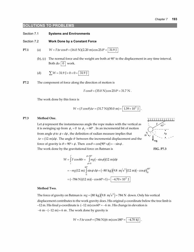
P7.3 Method One.
Let φ represent the instantaneous angle the rope makes with the vertical asit is swinging up from φ i = 0 to φ f = °60 . In an incremental bit of motion
from angle φ to φ φ+ d , the definition of radian measure implies that
∆r d= 12 ma f φ . The angle θ between the incremental displacement and the
force of gravity is θ φ= °+90 . Then cos cos sinθ φ φ= °+ = −90b g .
The work done by the gravitational force on Batman is FIG. P7.3
W F dr mg d
mg d
i
f
= = −
= − = − −
= − − °+ = − ×
z zz
=
= °
°°
cos sin
sin . cos
cos .
θ φ φ
φ φ φ
φ
φ
b ga f
a f b ge ja fb g
a fa fa f
12
12 80 9 8 12
784 12 60 1 4 70 10
0
60
0
60
0
60
3
m
m kg m s m
N m J
2
Method Two.
The force of gravity on Batman is mg = =80 9 8 784 kg m s N2b ge j. down. Only his vertical
displacement contributes to the work gravity does. His original y-coordinate below the tree limb is–12 m. His final y-coordinate is − °= −12 60 6 m ma fcos . His change in elevation is
− − − =6 12 6 m m ma f . The work done by gravity is
W F r= = °= −∆ cos cos .θ 784 6 180 4 70 N m kJa fa f .
194 Energy and Energy Transfer
P7.4 (a) W mgh= = × = ×− −3 35 10 9 80 100 3 28 105 2. . .e ja fa f J J
(b) Since R mg= , Wair resistance J= − × −3 28 10 2.
Section 7.3 The Scalar Product of Two Vectors
P7.5 A = 5 00. ; B = 9 00. ; θ = °50 0.A B⋅ = = °=ABcos . . cos . .θ 5 00 9 00 50 0 28 9a fa f
P7.6 A B i j k i j k⋅ = + + ⋅ + +A A A B B Bx y z x y ze j e jA B i i i j i k
j i j j j k
k i k j k k
A B
⋅ = ⋅ + ⋅ + ⋅
+ ⋅ + ⋅ + ⋅
+ ⋅ + ⋅ + ⋅
⋅ = + +
A B A B A B
A B A B A B
A B A B A B
A B A B A B
x x x y x z
y x y y y z
z x z y z z
x x y y z z
e j e j e je j e j e je j e j e j
P7.7 (a) W F x F yx y= ⋅ = + = ⋅ + − ⋅ =F r∆ 6 00 3 00 2 00 1 00 16 0. . . . .a fa f a fa f N m N m J
(b) θ =⋅FHGIKJ =
+ − += °− −cos cos
. . . ..1 1
2 2 2 2
16
6 00 2 00 3 00 1 0036 9
F r∆∆F r a f a fe j a f a fe j
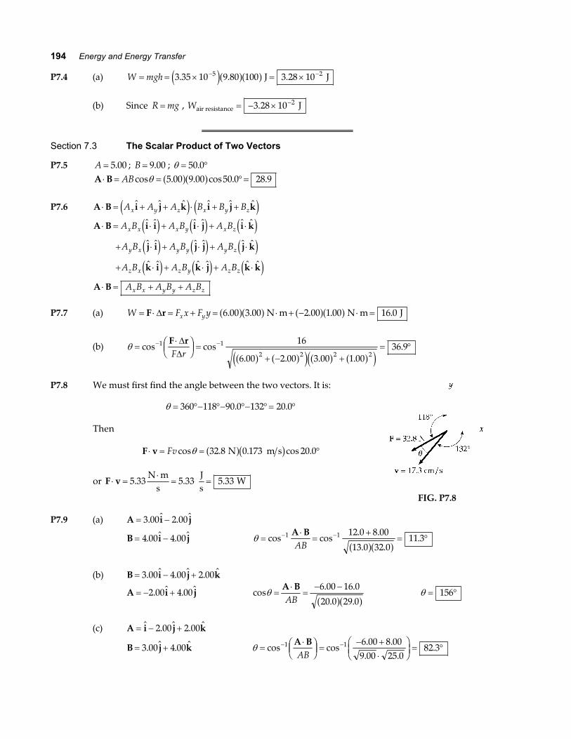
P7.8 We must first find the angle between the two vectors. It is:
θ = °− °− °− °= °360 118 90 0 132 20 0. .
Then
F v⋅ = = °Fv cos . . cos .θ 32 8 0 173 20 0 N m sa fb g
or F v⋅ =⋅
= =5 33 5 33 5 33. . .N m
s
Js
W
FIG. P7.8
P7.9 (a) A i j= −3 00 2 00. .
B i j= −4 00 4 00. . θ =⋅
=+
= °− −cos cos. .
. ..1 1 12 0 8 00
13 0 32 011 3
A BAB a fa f
(b) B i j k= − +3 00 4 00 2 00. . .
A i j= − +2 00 4 00. . cos. .
. .θ =
⋅=
− −A BAB
6 00 16 0
20 0 29 0a fa f θ = °156
(c) A i j k= − +. .2 00 2 00
B j k= +3 00 4 00. . θ =⋅FHGIKJ =
− +⋅
FHG
IKJ = °− −cos cos
. .. .
.1 1 6 00 8 009 00 25 0
82 3A BAB

Chapter 7 195
P7.10 A B i j k i j k− = + − − − + +3 00 2 00 5 00. . .e j e jA B i j k
C A B j k i j k
− = − −
⋅ − = − ⋅ − − = + − + + =
4 00 6 00
2 00 3 00 4 00 6 00 0 2 00 18 0 16 0
. .
. . . . . . .a f e j e j a f a f
Section 7.4 Work Done by a Varying Force
P7.11 W Fdxi
f
= =z area under curve from xi to x f
(a) xi = 0 x f = 8 00. m
W = area of triangle ABC AC= FHGIKJ ×
12
altitude,
W0 812
8 00 6 00 24 0→ = FHGIKJ × × =. . . m N J
(b) xi = 8 00. m x f = 10 0. m
W = area of ∆CDE CE= FHGIKJ ×
12
altitude,
W8 1012
2 00 3 00 3 00→ = FHGIKJ × × − = −. . . m N Ja f a f
(c) W W W0 10 0 8 8 10 24 0 3 00 21 0→ → →= + = + − =. . .a f J
FIG. P7.11
P7.12 F xx = −8 16a f N
(a) See figure to the right
(b) Wnet m N m N
J=−
+ = −2 00 16 0
21 00 8 00
212 0
. . . ..
a fa f a fa f
FIG. P7.12

196 Energy and Energy Transfer
P7.13 W F dxx= zand W equals the area under the Force-Displacement curve
(a) For the region 0 5 00≤ ≤x . m ,
W = =3 00 5 00
27 50
. ..
N m J
a fa f
(b) For the region 5 00 10 0. .≤ ≤x ,
W = =3 00 5 00 15 0. . . N m Ja fa f
(c) For the region 10 0 15 0. .≤ ≤x ,
W = =3 00 5 00
27 50
. ..
N m J
a fa f
(d) For the region 0 15 0≤ ≤x .
W = + + =7 50 7 50 15 0 30 0. . . .a f J J
FIG. P7.13
P7.14 W d x y dxi
f
= ⋅ = + ⋅z zF r i j i4 30
5
e j N m
4 0 42
50 00
5 2
0
5
N m N m J m m
b g b gxdxx
+ = =z .
P7.15 kFy
Mgy
= = =×
= ×−
4 00 9 80
2 50 101 57 102
3. .
..
a fa f N m
N m
(a) For 1.50 kg mass ymgk
= =×
=1 50 9 80
1 57 100 9383
. .
..
a fa f cm
(b) Work =12
2ky
Work = × ⋅ × =−12
1 57 10 4 00 10 1 253 2 2. . . N m m Je je j
P7.16 (a) Spring constant is given by F kx=
kFx
= = =230
0 400575
N m
N ma fa f.
(b) Work = = =F xavg N m J12
230 0 400 46 0a fa f. .

Chapter 7 197
*P7.17 (a) F k x k x k x k x y
x x
x
h happlied leaf helper
N Nm
Nm
m
N N m
m
= + = + −
× = × + × −
=××
=
0
5 5 5
5
5
5 10 5 25 10 3 60 10 0 5
6 8 108 85 10
0 768
b gb g. . .
..
.
(b) W k x k xh h= + = ×FHG
IKJ + ×
= ×
12
12
12
5 25 10 0 76812
3 60 10 0 268
1 68 10
2 2 5 2 5 2
5
. . . .
.
Nm
m Nm
m
J
a f a f
P7.18 (a) W d
W x x dx
W xx x
W
i
f
= ⋅
= + − °
= + −
= + − =
zz
F r
15 000 10 000 25 000 0
15 00010 000
225 000
3
9 00 1 80 1 80 9 00
2
0
0 600
2 3
0
0 600
N N m N m
kJ kJ kJ kJ
2 m
m
e j cos
. . . .
.
.
(b) Similarly,
W
W
= + −
=
15 0 1 0010 0 1 00
2
25 0 1 00
311 7
2 3
. .. . . .
.
kN m kN m m kN m m
kJ , larger by 29.6%
2
a fa f b ga f e ja f
P7.19 4 0012
0 100 2. . J m= ka f∴ =k 800 N m and to stretch the spring to 0.200 m requires
∆W = − =12
800 0 200 4 00 12 02a fa f. . . J J
P7.20 (a) The radius to the object makes angle θ with the horizontal, soits weight makes angle θ with the negative side of the x-axis,when we take the x–axis in the direction of motion tangent tothe cylinder.
F ma
F mg
F mg
x x∑ =
− =
=
cos
cos
θ
θ
0
FIG. P7.20
(b) W di
f
= ⋅z F r
We use radian measure to express the next bit of displacement as dr Rd= θ in terms of thenext bit of angle moved through:
W mg Rd mgR
W mgR mgR
= =
= − =
z cos sinθ θ θπ
π
0
2
0
2
1 0a f
198 Energy and Energy Transfer
*P7.21 The same force makes both light springs stretch.
(a) The hanging mass moves down by
x x xmgk
mgk
mgk k
= + = + = +FHG
IKJ
= +FHG
IKJ = × −
1 21 2 1 2
2
1 1
1 51
1 2001
2 04 10. . kg 9.8 m s m
N m
1 800 N m2
(b) We define the effective spring constant as
kFx
mgmg k k k k
= =+
= +FHG
IKJ
= +FHG
IKJ =
−
−
1 11 1
1 1720
1 2 1 2
1
1
b g m
1 200 N m
1 800 N N m
*P7.22 See the solution to problem 7.21.
(a) x mgk k
= +FHG
IKJ
1 1
1 2
(b) kk k
= +FHG
IKJ−
1 1
1 2
1
P7.23 kFx
= LNMOQP = =
⋅=
Nm
kg m sm
kgs
2
2
Section 7.5 Kinetic Energy and the Work-Kinetic Energy Theorem
Section 7.6 The Non-Isolated System—Conservation of Energy
P7.24 (a) K A = =12
0 600 2 00 1 202
. . . kg m s Jb gb g
(b)12
2mv KB B= : vKmB
B= = =2 2 7 50
0 6005 00
a fa f..
. m s
(c) W K K K m v vB A B A∑ = = − = − = − =∆12
7 50 1 20 6 302 2e j . . . J J J
P7.25 (a) K mv= = =12
12
0 300 15 0 33 82 2. . . kg m s Jb gb g
(b) K = = = =12
0 300 30 012
0 300 15 0 4 4 33 8 1352 2. . . . .a fa f a fa f a f a f J

Chapter 7 199
P7.26 v i ji = − =6 00 2 00. .e j m s
(a) v v vi ix iy= + =2 2 40 0. m s
K mvi i= = =12
12
3 00 40 0 60 02 . . . kg m s J2 2b ge j
(b) v i jf = +8 00 4 00. .
v f f f2 64 0 16 0 80 0= ⋅ = + =v v . . . m s2 2
∆K K K m v vf i f i= − = − = − =12
3 002
80 0 60 0 60 02 2e j a f.. . . J
P7.27 Consider the work done on the pile driver from the time it starts from rest until it comes to rest atthe end of the fall. Let d = 5.00 m represent the distance over which the driver falls freely, andh = 0 12. m the distance it moves the piling.
W K∑ = ∆ : W W mv mvf igravity beam+ = −12
12
2 2
so mg h d F db ga f d ia f+ °+ °= −cos cos0 180 0 0 .
Thus, Fmg h d
d=
+= = ×
b ga f b ge ja f2 100 9 80 5 12
0 1208 78 105
kg m s m
m N
2. .
.. . The force on the pile
driver is upward .
P7.28 (a) ∆K K K mv Wf i f= − = − = =∑12
02 (area under curve from x = 0 to x = 5 00. m)
vmf = = =
2 2 7 504 00
1 94area J
kg m s
a f a f..
.
(b) ∆K K K mv Wf i f= − = − = =∑12
02 (area under curve from x = 0 to x = 10 0. m)
vmf = = =
2 2 22 54 00
3 35area J
kg m s
a f a f..
.
(c) ∆K K K mv Wf i f= − = − = =∑12
02 (area under curve from x = 0 to x = 15 0. m)
vmf = = =
2 2 30 04 00
3 87area J
kg m s
a f a f..
.
P7.29 (a) K W K mvi f f+ = =∑ 12
2
012
15 0 10 780 4 563 2+ = × =∑ −W . . kg m s kJe jb g
(b) FW
r= =
×°=
∆ cos.
cos.
θ4 56 10
06 34
3 J0.720 m
kNa f
(c) av v
xf i
f=
−=
−=
2 2 2
2
780 0
2 0 720422
m s
m km s2b g
a f.
(d) F ma∑ = = × × =−15 10 422 10 6 343 3 kg m s kN2e je j .
200 Energy and Energy Transfer
P7.30 (a) v f = × = ×0 096 3 10 2 88 108 7. . m s m se jK mvf f= = × × = ×− −1
212
9 11 10 2 88 10 3 78 102 31 7 2 16. . . kg m s Je je j
(b) K W Ki f+ = : 0 + =F r K f∆ cosθ
F 0 028 0 3 78 10 16. cos . m Ja f °= × −
F = × −1 35 10 14. N
(c) F ma∑ = ; aF
m= =
××
= ×∑ −
−+1 35 10
9 11 101 48 10
14
3116.
..
N kg
m s2
(d) v v a txf xi x= + 2 88 10 0 1 48 107 16. .× = + × m s m s2e jtt = × −1 94 10 9. s
Check: x x v v tf i xi xf= + +12d i
0 028 012
0 2 88 107. . m m s= + + ×e jtt = × −1 94 10 9. s
Section 7.7 Situations Involving Kinetic Friction
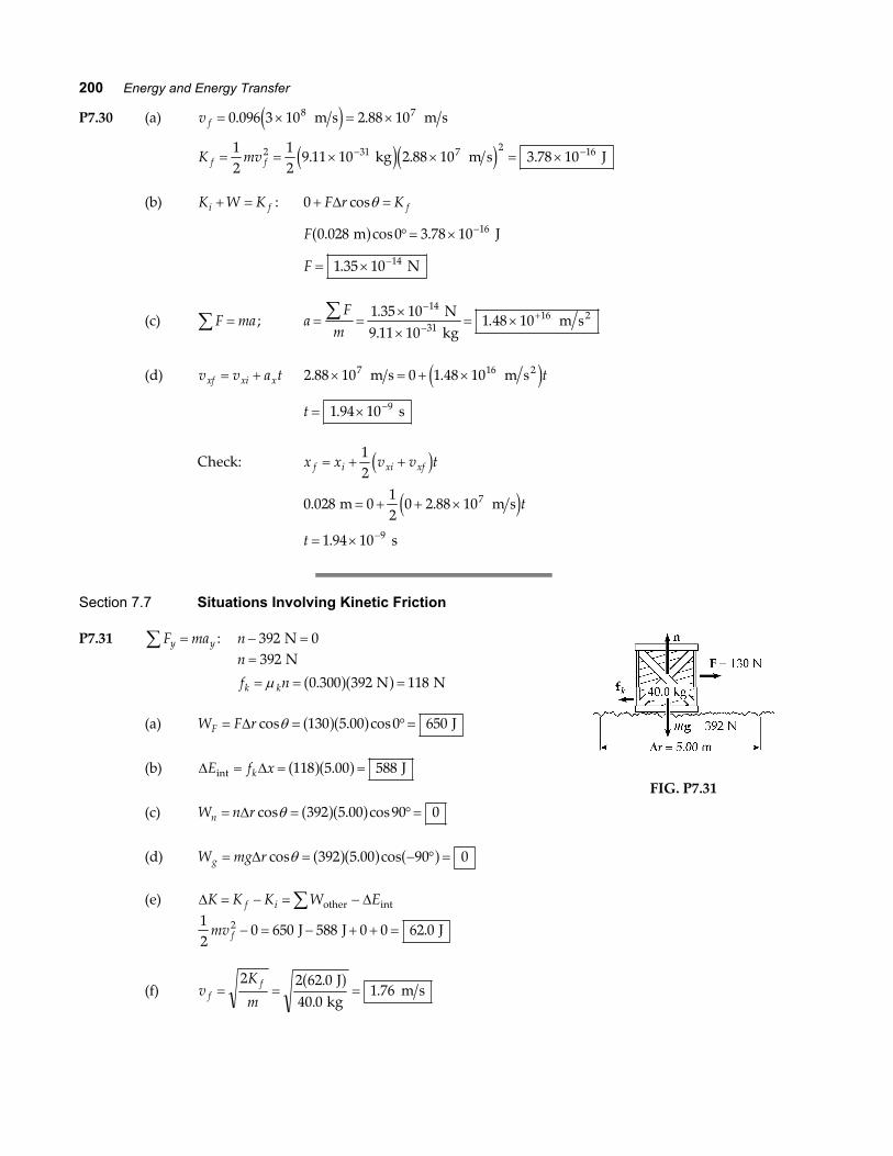
P7.31 F may y∑ = : n − =392 0 Nn
f nk k
=
= = =
392
0 300 392 118
N
N Nµ .a fa f
(a) W F rF = = °=∆ cos . cosθ 130 5 00 0 650a fa f J
(b) ∆ ∆E f xkint J= = =118 5 00 588a fa f.
(c) W n rn = = °=∆ cos . cosθ 392 5 00 90 0a fa fFIG. P7.31
(d) W mg rg = = − ° =∆ cos . cosθ 392 5 00 90 0a fa f a f
(e) ∆ ∆K K K W Ef i= − = −∑ other int
12
0 650 588 0 0 62 02mv f − = − + + = J J J.
(f) vK
mff= = =
2 2 62 040 0
1 76.
..
J kg
m sa f
Chapter 7 201
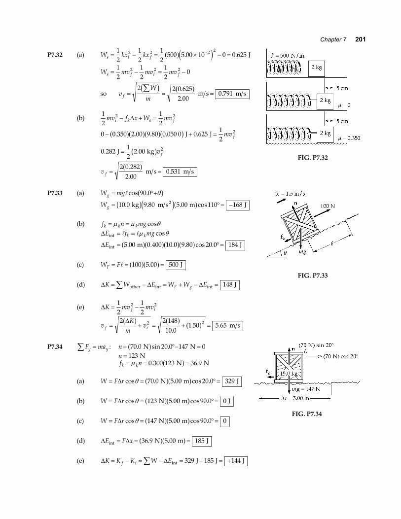
P7.32 (a) W kx kxs i f= − = × − =−12
12
12
500 5 00 10 0 0 6252 2 2 2a fe j. . J
W mv mv mvs f i f= − = −12
12
12
02 2 2
so vW
mf = = =∑2 2 0 625
2 000 791
c h a f..
. m s m s
(b)12
12
2 2mv f x W mvi k s f− + =∆
0 0 350 2 00 9 80 0 050 0 0 62512
0 28212
2 00
2 0 2822 00
0 531
2
2
− + =
=
= =
. . . . .
. .
.
..
a fa fa fb g
b ga f
J J
J kg
m s m s
mv
v
v
f
f
f
FIG. P7.32
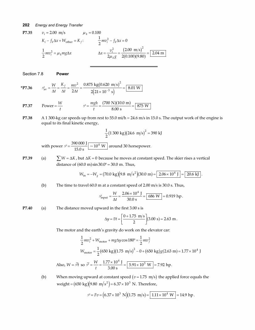
P7.33 (a) W mgg = °+cos .90 0 θa fWg = °= −10 0 9 80 5 00 110 1682. . . cos kg m s m Jb gd ia f
(b) f n mgk k k= =µ µ θcos∆
∆
E f mg
Ek kint
int m J
= =
= °=
µ θcos
. . . . cos .5 00 0 400 10 0 9 80 20 0 184a fa fa fa f
(c) W FF = = =100 5 00 500a fa f. J
(d) ∆ ∆ ∆K W E W W EF g= − = + − =∑ other int int J148FIG. P7.33
(e) ∆K mv mvf i= −12
12
2 2
vK
mvf i= + = + =
2 2 14810 0
1 50 5 652 2∆a f a f a f.
. . m s
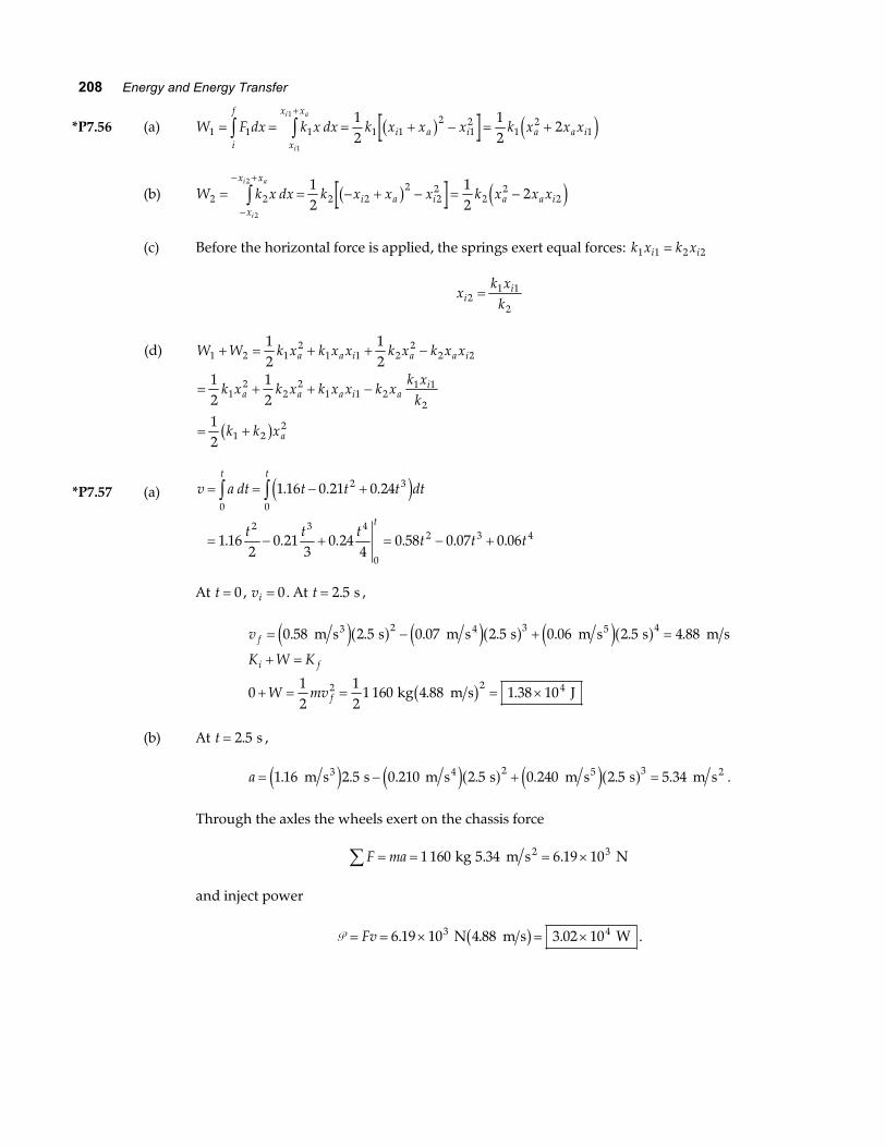
P7.34 F may y∑ = : n + °− =70 0 20 0 147 0. sin . N Na fn = 123 Nf nk k= = =µ 0 300 123 36 9. . N Na f
(a) W F r= = °=∆ cos . . cos .θ 70 0 5 00 20 0 329 N m Ja fa f
(b) W F r= = °=∆ cos . cos .θ 123 5 00 90 0 0 N m Ja fa f
(c) W F r= = °=∆ cos . cos .θ 147 5 00 90 0 0 N ma fa fFIG. P7.34
(d) ∆ ∆E F xint N m J= = =36 9 5 00 185. .a fa f
(e) ∆ ∆K K K W Ef i= − = − = − = +∑ int J J J329 185 144
202 Energy and Energy Transfer
P7.35 vi = 2 00. m s µ k = 0 100.
K f x W Ki k f− + =∆ other :12
02mv f xi k− =∆
12
2mv mg xi k= µ ∆ ∆xv
gi
k= = =
2 2
2
2 00
2 0 100 9 802 04
µ.
. ..
m s m
b ga fa f
Section 7.8 Power
*P7.36 Pav kg m s
s W= = = =
×=
−
Wt
K
tmv
tf
∆ ∆ ∆
2 2
32
0 875 0 620
2 21 108 01
. ..
b ge j
P7.37 Power =Wt
P = = =mgh
t700 10 0
8 00875
N m s
Wa fa f.
.
P7.38 A 1 300-kg car speeds up from rest to 55.0 mi/h = 24.6 m/s in 15.0 s. The output work of the engine isequal to its final kinetic energy,
12
1 300 24 6 3902
kg m s kJb gb g. =
with power P =390 000
104 J15.0 s
W~ around 30 horsepower.
P7.39 (a) W K∑ = ∆ , but ∆K = 0 because he moves at constant speed. The skier rises a verticaldistance of 60 0 30 0 30 0. sin . . m ma f °= . Thus,
W Wgin2 kg m s m J kJ= − = = × =70 0 9 8 30 0 2 06 10 20 64. . . . .b ge ja f .
(b) The time to travel 60.0 m at a constant speed of 2.00 m/s is 30.0 s. Thus,
Pinput J
30.0 s W hp= =
×= =
Wt∆
2 06 10686 0 919
4.. .
P7.40 (a) The distance moved upward in the first 3.00 s is
∆y vt= =+LNM
OQP =
0 1 752
3 00 2 63.
. . m s
s ma f .
The motor and the earth’s gravity do work on the elevator car:
12
18012
12
650 1 75 0 650 2 63 1 77 10
2 2
2 4
mv W mg y mv
W g
i f+ + °=
= − + = ×
motor
motor kg m s kg m J
∆ cos
. . .b gb g b g a f
Also, W t= P so P = =×
= × =Wt
1 77 105 91 10 7 92
43.
. . J
3.00 s W hp.
(b) When moving upward at constant speed v = 1 75. m sb g the applied force equals the
weight kg m s N2= = ×650 9 80 6 37 103b ge j. . . Therefore,
P = = × = × =Fv 6 37 10 1 75 1 11 10 14 93 4. . . . N m s W hpe jb g .

Chapter 7 203
P7.41 energy power time= ×
For the 28.0 W bulb:
Energy used = × = ⋅28 0 1 00 10 2804. . W h kilowatt hrsa fe jtotal cost = + =$17. $0. $39.00 280 080 40 kWh kWha fb g
For the 100 W bulb:
Energy used = × = × ⋅100 1 00 10 1 00 104 3 W h kilowatt hrsa fe j. .
# bulb used =×
=1 00 10
13 34.
. h
750 h bulb
total cost = + × =13 3 420 1 00 10 080 603. $0. . $0. $85.b g e jb g kWh kWh
Savings with energy-efficient bulb = − =$85. $39. $46.60 40 20
*P7.42 (a) Burning 1 lb of fat releases energy 19 4 186
1 71 107 lb454 g1 lb
kcal1 g
J1 kcal
JFHGIKJFHG
IKJFHG
IKJ = ×. .
The mechanical energy output is 1 71 10 0 207. . cos× = Je ja f nF r∆ θ .
Then 3 42 10 06. cos× = ° J nmg y∆
3 42 10 50 9 8 80 0 150
3 42 10 5 88 10
6
6 3
. . .
. .
× =
× = ×
J kg m s steps m
J J
2n
n
b ge jb ga fe j
where the number of times she must climb the steps is n =××
=3 42 105 88 10
5826
3..
J J
.
This method is impractical compared to limiting food intake.
(b) Her mechanical power output is
P = =×
= = FHG
IKJ =
Wt
5 88 1090 5 90 5
10 121
3.. . .
J65 s
W W hp
746 W hp .
*P7.43 (a) The fuel economy for walking is 1 3 1 1 30 10
4238 h
220 kcal mih
kcal4 186 J
J1 gal
mi galFHGIKJFHG
IKJ
×FHG
IKJ =
..
(b) For bicycling 1 10 1 30 10
7768 h
400 kcal mih
1 kcal4 186 J
J1 gal
mi galFHGIKJFHG
IKJ
×FHG
IKJ =
..

204 Energy and Energy Transfer
Section 7.9 Energy and the Automobile
P7.44 At a speed of 26.8 m/s (60.0 mph), the car described in Table 7.2 delivers a power of P1 18 3= . kW tothe wheels. If an additional load of 350 kg is added to the car, a larger output power of
P P2 1= + (power input to move 350 kg at speed v)
will be required. The additional power output needed to move 350 kg at speed v is:
∆ ∆Pout = =f v mg vrb g b gµ .
Assuming a coefficient of rolling friction of µ r = 0 016 0. , the power output now needed from theengine is
P P2 1 0 016 0 350 9 80 26 8 18 3 1 47= + = +. . . . .b gb ge jb g kg m s m s kW kW2 .
With the assumption of constant efficiency of the engine, the input power must increase by thesame factor as the output power. Thus, the fuel economy must decrease by this factor:
fuel economy fuel economy km Lb g b g b g21
21
18 318 3 1 47
6 40=FHGIKJ =
+FHG
IKJ
PP
.. .
.
or fuel economy km Lb g2 5 92= . .
P7.45 (a) fuel needed =−
=−
×
12
2 12
2 12
2 0mv mv mvf i f
useful energy per gallon eff. energy content of fuelb g=
×= × −
12
2
82900 24 6
0 150 1 34 101 35 10
kg m s
J gal gal
b gb ga fe j
.
. ..
(b) 73 8.
(c) power = FHGIKJFHG
IKJFHG
IKJ
×FHG
IKJ =
138 0
55 0 1 00 1 34 100 150 8 08
8 gal mi
mi1.00 h
h3 600 s
J1 gal
kW.
. . .. .a f
Additional Problems
P7.46 At start, v i j= ° + °40 0 30 0 40 0 30 0. cos . . sin . m s m sb g b gAt apex, v i j i= ° + =40 0 30 0 0 34 6. cos . . m s m sb g b gAnd K mv= = =
12
12
0 150 34 6 90 02 2. . . kg m s Jb gb g

Chapter 7 205
P7.47 Concentration of Energy output = ⋅ FHG
IKJ =0 600 60 0
124 0. . . J kg step kg
step1.50 m
J mb gb g
F
Fv
v
v
= ⋅ =
=
=
=
24 0 1 24 0
70 0 24 0
2 92
. .
. .
.
J m N m J N
W N
m s
b gb g
a fP
P7.48 (a) A i⋅ = cosAa fa f1 α . But also, A i⋅ = Ax .
Thus, A Axa fa f1 cosα = or cosα =AA
x .
Similarly, cosβ =A
Ay
and cosγ =AA
z
where A A A Ax y z= + +2 2 2 .
(b) cos cos cos2 2 22 2 2 2
2 1α β γ+ + = FHGIKJ +FHGIKJ + FHG
IKJ = =
AA
A
AAA
AA
x y z
P7.49 (a) x t t= + 2 00 3.
Therefore,
vdxdt
t
K mv t t t
= = +
= = + = + +
1 6 00
12
12
4 00 1 6 00 2 00 24 0 72 0
2
2 2 2 2 4
.
. . . . .a fe j e j J
(b) advdt
t= = 12 0.a f m s2
F ma t t= = =4 00 12 0 48 0. . .a f a f N
(c) P = = + = +Fv t t t t48 0 1 6 00 48 0 2882 3. . .a fe j e j W
(d) W dt t t dt= = + =z zP0
2 003
0
2 00
48 0 288 1 250. .
.e j J

206 Energy and Energy Transfer
*P7.50 (a) We write
F ax
a
a
b
b b
a a
b
b
b
bb
=
=
=
= FHGIKJ =
=
= = =
= = × =
1 000 0 129
5 000 0 315
50 3150 129
2 44
5 2 445
2 441 80
1 0004 01 101.80
4
N m
N m
N
0.129 m N m1.8
.
.
.
..
ln ln .ln
ln ..
.
a fa f
a f
(b) W Fdx x dx
x
= = ×
= × = ×
=
z z0
0 254 1.8
0
0 25
42 8
0
0 254
2 8
4 01 10
4 01 102 8
4 01 100 25
2 8
294
. .
. . .
.
..
..
.
m
1.8
m
1.8
m
1.8
N
m
N
m
Nm
m
J
a f
*P7.51 The work done by the applied force is
W F dx k x k x dx
k x dx k x dx kx
kx
kx
kx
i
f x
x x x x
= = − − +
= + = +
= +
z zz z
applied 1 22
0
10
22
01
2
02
3
0
1
2
2
3
2 3
2 3
e jmax
max max max max
max max
P7.52 (a) The work done by the traveler is mgh Ns where N is the number of steps he climbs duringthe ride.
N = (time on escalator)(n)
where time on escalatorvertical velocity of person
a f = h
and vertical velocity of person = +v nhs
Then, Nnh
v nhs=
+
and the work done by the person becomes Wmgnhhv nh
s
sperson =
+
continued on next page

Chapter 7 207
(b) The work done by the escalator is
W mgvte = = =power time force exerted speed timeb ga f a fb ga f
where th
v nhs=
+ as above.
Thus, Wmgvh
v nhes
=+
.
As a check, the total work done on the person’s body must add up to mgh, the work anelevator would do in lifting him.
It does add up as follows: W W Wmgnhhv nh
mgvhv nh
mgh nh vv nh
mghes
s s
s
s∑ = + =
++
+=
+
+=person
b g
P7.53 (a) ∆K mv W= − = ∑12
02 , so
vWm
2 2= and v
Wm
=2
(b) W F d FWdx x= ⋅ = ⇒ =F d
*P7.54 During its whole motion from y = 10 0. m to y = −3 20. mm, the force of gravity and the force of theplate do work on the ball. It starts and ends at rest
K W K
F y F x
mg F
F
i f
g p
p
p
+ =
+ °+ °=
− =
=×
= ×
∑
−
0 0 180 0
10 003 2 0 003 20 0
5 10
3 2 101 53 103
5
∆ ∆cos cos
. .
..
m m
kg 9.8 m s m
m N upward
2
b g b ge ja f
P7.55 (a) P = = + = +FHGIKJ =FHGIKJFv F v at F
Fm
tFm
tib g 02
(b) P =LNMM
OQPP =
20 05 00
3 00 2402.
..
N kg
s Wa f a f
208 Energy and Energy Transfer
*P7.56 (a) W F dx k x dx k x x x k x x xi
f
x
x x
i a i a a i
i
i a
1 1 1 1 12
12
12
1
1
1 12
12
2= = = + − = +z z+
b g e j
(b) W k x dx k x x x k x x xx
x x
i a i a a i
i
i a
2 2 2 22
22
22
2
2
2 12
12
2= = − + − = −−
− +
z b g e j
(c) Before the horizontal force is applied, the springs exert equal forces: k x k xi i1 1 2 2=
xk x
kii
21 1
2=
(d) W W k x k x x k x k x x
k x k x k x x k xk x
k
k k x
a a i a a i
a a a i ai
a
1 2 12
1 1 22
2 2
12
22
1 1 21 1
2
1 22
12
12
12
12
12
+ = + + −
= + + −
= +b g
*P7.57 (a) v a dt t t t dt
t t tt t t
t t
t
= = − +
= − + = − +
z z0
2 3
0
2 3 4
0
2 3 4
1 16 0 21 0 24
1 162
0 213
0 244
0 58 0 07 0 06
. . .
. . . . . .
e j
At t = 0 , vi = 0. At t = 2 5. s ,
v
K W K
W mv
f
i f
f
= − + =
+ =
+ = = = ×
0 58 2 5 0 07 2 5 0 06 2 5 4 88
012
12
1 160 4 88 1 38 10
2 3 4
2 2 4
. . . . . . .
. .
m s s m s s m s s m s
kg m s J
3 4 5e ja f e ja f e ja f
b g
(b) At t = 2 5. s ,
a = − + =1 16 2 5 2 5 0 240 2 5 5 342 3. . . . . . m s s 0.210 m s s m s s m s3 4 5 2e j e ja f e ja f .
Through the axles the wheels exert on the chassis force
F ma∑ = = = ×1 160 5 34 6 19 103 kg m s N2. .
and inject power
P = = × = ×Fv 6 19 10 4 88 3 02 103 4. . . N m s Wb g .

Chapter 7 209
P7.58 (a) The new length of each spring is x L2 2+ , so its extension is
x L L2 2+ − and the force it exerts is k x L L2 2+ −FH IK toward its
fixed end. The y components of the two spring forces add tozero. Their x components add to
F i i= − + −FH IK += − −
+
FHG
IKJ2 2 12 2
2 2 2 2k x L L
x
x Lkx
L
x L. FIG. P7.58
(b) W F dxxi
f
= z W kxL
x Ldx
A
= − −+
FHG
IKJz 2 1
2 2
0
W k x dx kL x L x dxA A
= − + +z z −2 2
02 2 1 20
e j W kx
kLx L
AA
= − ++
22 1 2
2 0 2 2 1 2 0
e jb g
W kA kL kL A L= − + + − +0 2 22 2 2 2 W kL kA kL A L= + − +2 22 2 2 2
*P7.59 For the rocket falling at terminal speed we have
F ma
R Mg
Mg D AvT
∑ =
+ − =
=
012
2ρ
(a) For the rocket with engine exerting thrust T and flying up at the same speed,
F ma
T Mg RT Mg
∑ =
+ − − ==
02
The engine power is P = = =Fv Tv MgvT T2 .
(b) For the rocket with engine exerting thrust Tb and flying down steadily at 3vT ,
R D A v Mgb T= =12
3 92ρ b g
F ma
T Mg MgT Mg
b
b
∑ =
− − + ==
9 08
The engine power is P = = =Tv Mg v MgvT T8 3 24 .
210 Energy and Energy Transfer
P7.60 (a) F i j i j1 25 0 35 0 35 0 20 5 14 3= ° + ° = +. cos . sin . . . N Na fe j e j
F i j i j2 42 0 150 150 36 4 21 0= ° + ° = − +. cos sin . . N Na fe j e j
(b) F F F i j∑ = + = − +1 2 15 9 35 3. .e j N
(c) aF
i j= = − +∑m
3 18 7 07. .e j m s2
(d) v v a i j i jf i t= + = + + − +4 00 2 50 3 18 7 07 3 00. . . . .e j e je ja f m s m s s2
v i jf = − +5 54 23 7. .e j m s
(e) r r v af i it t= + +12
2
r i j i j
r r i j
f
f
= + + + − +
= = − +
0 4 00 2 50 3 0012
3 18 7 07 3 00
2 30 39 3
2. . . . . .
. .
e jb ga f e je ja f
e j
m s s m s s
m
2
∆
(f) K mvf f= = + =12
12
5 00 5 54 23 7 1 482 2 2. . . . kg m s kJ2b g a f a f e j
(g) K mvf i= + ⋅∑12
2 F r∆
K
K
f
f
= + + − − +
= + =
12
5 00 4 00 2 50 15 9 2 30 35 3 39 3
55 6 1 426 1 48
2 2 2. . . . . . .
. .
kg m s N m N m
J J kJ
b g a f a f b g a fa f a fa f
P7.61 (a) W K∑ = ∆ : W Ws g+ = 012
0 90 60 0
12
1 40 10 0 100 0 200 9 80 60 0 0
4 12
2
3 2
kx mg x
x
x
i − + °+ ° =
× × − ° =
=
∆
∆
∆
cos
. . . . sin .
.
a f
e j a f a fa fa f N m
m
(b) W K E∑ = +∆ ∆ int : W W Es g+ − =∆ int 012
150 60 0
12
1 40 10 0 100 0 200 9 80 60 0 0 200 9 80 0 400 60 0 0
3 35
2
3 2
kx mg x mg x
x x
x
i k+ °− ° =
× × − ° − ° =
=
∆ ∆
∆ ∆
∆
cos cos
. . . . sin . . . . cos .
.
µ
N m
m
e j a f a fa fa f a fa fa fa f

Chapter 7 211
P7.62 (a) F L F LN mm N mm
2.004.006.008.0010.012.0
15.032.049.064.079.098.0
14.016.018.020.022.0
112126149175190
a f a f a f a f
FIG. P7.62
(b) A straight line fits the first eight points, together with the origin. By least-square fitting, itsslope is
0 125 2% 125 2%. N mm N m± = ±
In F kx= , the spring constant is kFx
= , the same as the slope of the F-versus-x graph.
(c) F kx= = =125 0 105 13 1 N m m Nb ga f. .
P7.63 K W W K
mv kx kx mg x mv
kx mgx mv
i s g f
i i f f
i i f
+ + =
+ − + =
+ − + °=
12
12
12
12
012
0 10012
2 2 2 2
2 2
∆ cos
cos
θ
FIG. P7.63
12
1 20 5 00 0 050 0 0 100 9 80 0 050 0 10 012
0 100
0 150 8 51 10 0 050 0
0 1410 050 0
1 68
2
3 2
. . . . . . sin . .
. . .
..
.
N cm cm m kg m s m kg
J J kg
m s
2b ga fb g b ge jb g b gb g
− °=
− × =
= =
−
v
v
v
P7.64 (a) ∆ ∆E K m v vf iint = − = − −12
2 2e j: ∆Eint kg m s J= − − =12
0 400 6 00 8 00 5 602 2 2. . . .b g a f a fe jb g
(b) ∆ ∆E f r mg rkint = = µ π2a f: 5 60 0 400 9 80 2 1 50. . . . J kg m s m2= µ πk b ge j a fThus, µ k = 0 152. .
(c) After N revolutions, the object comes to rest and K f = 0 .
Thus, ∆ ∆E K K mvi iint = − = − + =012
2
or µ πk img N r mv212
2a f = .
This gives Nmv
mg ri
k= = =
12
2 12
2
2
8 00
0 152 9 80 2 1 502 28
µ π πa fb g
a fe j a f.
. . ..
m s
m s m rev
2.

212 Energy and Energy Transfer
P7.65 If positive F represents an outward force, (same as direction as r), then
W d F r F r dr
WF r F r
WF r r F r r F
r rF
r r
W r r r r
W
i
f
r
r
r
r
f i f if i f i
f i f i
i
f
i
f
= ⋅ = −
=−
−−
=− −
+−
= − − −
= × − − × −
= × × −
z z − −
− −
− − − −− − − −
− − − − − −
− −
F r 2
212 6
6 6 6 6
1 03 10 1 89 10
1 03 10 1 88 10 2
013 13
07 7
013 12
07 6
013 12 12
07 6 6
07
6 6 013
12 12
77 6 6 134 12 12
77 6
σ σ
σ σ
σ σ σ σ
e j
e j e j
. .
. . . . . .
. . .
44 10 10 1 89 10 3 54 10 5 96 10 10
2 49 10 1 12 10 1 37 10
6 60 134 12 8 120
21 21 21
× − × × − ×
= − × + × = − ×
− − − −
− − −W J J J
P7.66 P∆ ∆∆
t W Km v
= = =a f 2
2
The density is ρ = =∆ ∆
∆m m
A xvol.
Substituting this into the first equation and solving for P , since ∆∆
xt
v= ,
for a constant speed, we get P =ρAv3
2.
FIG. P7.66
Also, since P = Fv , FAv
=ρ 2
2.
Our model predicts the same proportionalities as the empirical equation, and gives D = 1 for thedrag coefficient. Air actually slips around the moving object, instead of accumulating in front of it.For this reason, the drag coefficient is not necessarily unity. It is typically less than one for astreamlined object and can be greater than one if the airflow around the object is complicated.
P7.67 We evaluate 375
3 75312 8
23 7 dxx x+z ..
.
by calculating
375 0 100
12 8 3 75 12 8
375 0 100
12 9 3 75 12 9
375 0 100
23 6 3 75 23 60 8063 3 3
.
. . .
.
. . .
.
. . ..
a fa f a f
a fa f a f
a fa f a f+
++
++
=…
and
375 0 100
12 9 3 75 12 9
375 0 100
13 0 3 75 13 0
375 0 100
23 7 3 75 23 70 7913 3 3
.
. . .
.
. . .
.
. . ..
a fa f a f
a fa f a f
a fa f a f+
++
++
=… .
The answer must be between these two values. We may find it more precisely by using a value for∆x smaller than 0.100. Thus, we find the integral to be 0 799. N m⋅ .
Chapter 7 213
*P7.68 P =12
2 3D r vρπ
(a) Pa = = ×12
1 1 20 1 5 8 2 17 102 3 3. . . kg m m m s W3e j a f b gπ
(b)PP
b
a
b
a
vv
= =FHG
IKJ = =
3
3
3324
83 27
m s m s
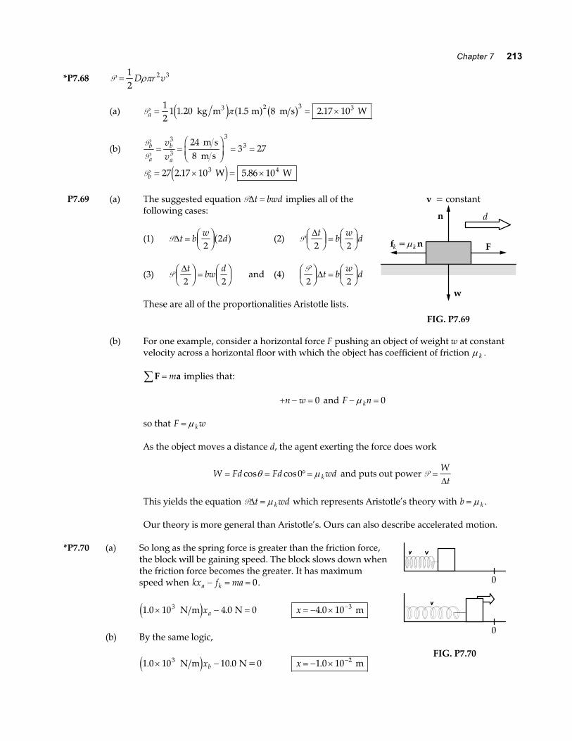
Pb = × = ×27 2 17 10 5 86 103 4. . W We jP7.69 (a) The suggested equation P∆t bwd= implies all of the
following cases:
(1) P∆t bw
d= FHGIKJ2
2a f (2) P∆t
bw
d2 2FHGIKJ =FHGIKJ
(3) P∆t
bwd
2 2FHGIKJ =FHGIKJ and (4)
P2 2FHGIKJ = FHG
IKJ∆t b
wd
These are all of the proportionalities Aristotle lists.
Ffk =µ k n
n
w
d
v = constant
FIG. P7.69
(b) For one example, consider a horizontal force F pushing an object of weight w at constantvelocity across a horizontal floor with which the object has coefficient of friction µ k .
F a∑ = m implies that:
+ − =n w 0 and F nk− =µ 0
so that F wk= µ
As the object moves a distance d, the agent exerting the force does work
W Fd Fd wdk= = °=cos cosθ µ0 and puts out power P =W
t∆
This yields the equation P∆t wdk= µ which represents Aristotle’s theory with b k= µ .
Our theory is more general than Aristotle’s. Ours can also describe accelerated motion.
*P7.70 (a) So long as the spring force is greater than the friction force,the block will be gaining speed. The block slows down whenthe friction force becomes the greater. It has maximumspeed when kx f maa k− = = 0.
1 0 10 4 0 03. .× − = N m Ne jxa x = − × −4 0 10 3. m
(b) By the same logic,
1 0 10 10 03. .× − N m N =0e jxb x = − × −1 0 10 2. m
0
0
FIG. P7.70

214 Energy and Energy Transfer
ANSWERS TO EVEN PROBLEMS
P7.2 1 59 103. × J P7.44 5 92. km L
P7.46 90.0 JP7.4 (a) 3 28 10 2. × − J ; (b) − × −3 28 10 2. J
P7.48 (a) cosα =AA
x ; cosβ =A
Ay ; cosγ =
AA
z ;P7.6 see the solution
(b) see the solutionP7.8 5.33 W
P7.50 (a) am
=40 1
1.8. kN
; b = 1 80. ; (b) 294 JP7.10 16.0
P7.12 (a) see the solution; (b) −12 0. J
P7.52 (a) mgnhhv nh
s
s+; (b)
mgvhv nhs+P7.14 50.0 J
P7.16 (a) 575 N m; (b) 46.0 J P7.54 1 53 105. × N upward
P7.18 (a) 9.00 kJ; (b) 11.7 kJ, larger by 29.6% P7.56 see the solution
P7.20 (a) see the solution; (b) mgR P7.58 (a) see the solution;
(b) 2 22 2 2 2kL kA kL A L+ − +P7.22 (a)
mgk
mgk1 2
+ ; (b) 1 1
1 2
1
k k+
FHG
IKJ−
P7.60 (a) F i j1 20 5 14 3= +. .e j N ;
F i j2 36 4 21 0= − +. .e j N;P7.24 (a) 1.20 J; (b) 5 00. m s ; (c) 6.30 J
(b) − +15 9 35 3. .i je j N ;P7.26 (a) 60.0 J; (b) 60.0 J
(c) − +3 18 7 07. .i je j m s2 ;P7.28 (a) 1 94. m s ; (b) 3 35. m s ; (c) 3 87. m s
(d) − +5 54 23 7. .i je j m s ;
P7.30 (a) 3 78 10 16. × − J; (b) 1 35 10 14. × − N ; (e) − +2 30 39 3. .i je j m ; (f) 1.48 kJ; (g) 1.48 kJ(c) 1 48 10 16. × + m s2 ; (d) 1.94 ns
P7.62 (a) see the solution; (b) 125 2% N m± ;P7.32 (a) 0 791. m s; (b) 0 531. m s(c) 13.1 N
P7.34 (a) 329 J; (b) 0; (c) 0; (d) 185 J; (e) 144 JP7.64 (a) 5.60 J; (b) 0.152; (c) 2.28 rev
P7.36 8.01 WP7.66 see the solution
P7.38 ~104 WP7.68 (a) 2.17 kW; (b) 58.6 kW
P7.40 (a) 5.91 kW; (b) 11.1 kWP7.70 (a) x = −4 0. mm; (b) −1 0. cm
P7.42 No. (a) 582; (b) 90 5 0 121. . W hp=