CHAPTER ONE INTRODUCTION - eng.najah.edu · of it’s soil is soft clay as mentioned in soil report...
91
Design of footings for Korean School Page | 1 CHAPTER ONE INTRODUCTION This chapter is devoted to describe the assigned project which is the Korean Industrial School at Jenin district .It concentrates also at investigation and understanding of the site and its surroundings. Finally the scope of the project is defied and stated at the end of this chapter . 1.1 THE SITE The proposed project was constructed at Jenin District which is located at the north of Palestine as shown in figure 1.1. Jenin city has many of villages around it, and the map in figure 1.2 shown how the villages surrounding around Jenin city . Our project located on Bait Qad street as shown in the figure 1.3, and it’s far from Bait Qad street about 600 m, and from Jenin city about 3 km . The school is located in an agricultural areas as shown in figure 1.4, and the type of it’s soil is soft clay as mentioned in soil report test .
Transcript of CHAPTER ONE INTRODUCTION - eng.najah.edu · of it’s soil is soft clay as mentioned in soil report...

Design of footings for Korean School P a g e | 1
CHAPTER ONE
INTRODUCTION
This chapter is devoted to describe the assigned project which is the
Korean Industrial School at Jenin district .It concentrates also at
investigation and understanding of the site and its surroundings.
Finally the scope of the project is defied and stated at the end of this
chapter .
1.1 THE SITE
The proposed project was constructed at Jenin District which is located at
the north of Palestine as shown in figure 1.1. Jenin city has many of
villages around it, and the map in figure 1.2 shown how the villages
surrounding around Jenin city .
Our project located on Bait Qad street as shown in the figure 1.3, and it’s
far from Bait Qad street about 600 m, and from Jenin city about 3 km . The
school is located in an agricultural areas as shown in figure 1.4, and the type
of it’s soil is soft clay as mentioned in soil report test .

Design of footings for Korean School P a g e | 2
Figure 1.1 : Palestine Map

Design of footings for Korean School P a g e | 3
Figure 1.2 : Jenin District

Design of footings for Korean School P a g e | 4
Figure 1.3 : location of the school relative to Jenin city

Design of footings for Korean School P a g e | 5
Figure 1.4 : the location of the school related to Beit Qad street

Design of footings for Korean School P a g e | 6
1.2 THE PROJECT
The existing building consists of four floors, each has class rooms,
corridors and various halls for educational purposes, the total area of
the school is 641.6 m2, the clear height of each floor is 3.44m. See
figure 1.5 .
The building is divided into two parts, 2.5 cm expansion joint is
separating the building- blocks, an expansion joint provides the
required distance to absorb the temperature-induced expansion and,
also it absorb vibration, and allows movement due to ground
settlement or earthquakes. It also has two stairs of same area, each
stair is surrounded by shear walls (i. e , work to keep the building
rigid and braced), they are located in a suitable location that
provides the building the needed rigidity. See figure 1.6 .

Design of footings for Korean School P a g e | 7
Figure 1.5: The school building

Design of footings for Korean School P a g e | 8
Figure 1.6 : Shear walls and expansion joint

Design of footings for Korean School P a g e | 9
1.3 SCOPE OF THE WORK
This project involves the following items :
1-Evalutation of the site and the project .
2-Selection of proper footings .
3-Design of the selected footings including combined footings, shear
walls, and a retaining wall .

Design of footings for Korean School P a g e | 10
CHAPTER TWO
LITERATURE REVIEW
Foundation may be classed according to their nature, their function,
the material they are constructed of , and according to method of
their analysis . All foundation however , may be classed generally as
(1) shallow (2) deep (3) special foundation.
If the foundation is laid directly on a component load bearing soil at
minimum depth below the ground surface such that the foundation is
safe against lateral expansion of soil from underneath the base of
footing and is also safe against volume changes of soil due to frost
action, swelling for examples, and shrinkage (settlement, heave) ,
one then speaks of a shallow foundation . Shallow foundation applies
mainly to buildings and certain engineering structures.
If , however , the load from the structure should be transmitted to a
considerable depth by means of end bearing piles , piers , and
caissons through weak soil to a geologic stratum component to
support the structural load , or by means of friction piles where no
underlying strong stratum is economically feasible , one then speaks
of a deep foundation . Deep foundation applies mainly to engineering
Design of footings for Korean School P a g e | 11
structures such ass bridges and hydraulic structures as well ass to
building if they have to be built on sites of poor soil. Wherever
possible, deep be avoided because their cost increase rabidly with
depth.
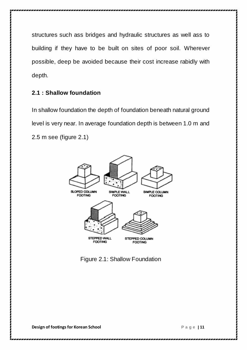
2.1 : Shallow foundation
In shallow foundation the depth of foundation beneath natural ground
level is very near. In average foundation depth is between 1.0 m and
2.5 m see (figure 2.1)
Figure 2.1: Shallow Foundation

Design of footings for Korean School P a g e | 12
We can use shallow foundation when the following conciliations are
fulfilled:
1- When there is good bearing stratum near the ground surface
and this layer can resist safely the stresses from footing.
2- When the expected settlements is within limit according to
surface nature.
3- When the cost of construction of this type of footing is
economic more than the other types.
There are two main types of shallow foundation:
1- When the good bearing soil stratum is near ground level Df
=(1- 2m) we shall put a layer of plain concrete over it then we
shall put a reinforced concrete footing over P.C . footing
2- When the good bearing silo stratum is relatively far from
ground level (Df= 2.5 - 3m) a part of the weak soil stratum is
replaced by a well compacted sandy gravel layer over this
replacement stratum we shall put the required footing (P.C.and
R.C).
Design of footings for Korean School P a g e | 13
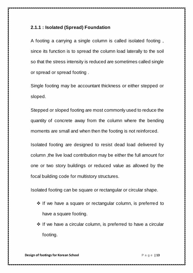
2.1.1 : Isolated (Spread) Foundation
A footing a carrying a single column is called isolated footing ,
since its function is to spread the column load laterally to the soil
so that the stress intensity is reduced are sometimes called single
or spread or spread footing .
Single footing may be accountant thickness or either stepped or
sloped.
Stepped or sloped footing are most commonly used to reduce the
quantity of concrete away from the column where the bending
moments are small and when then the footing is not reinforced.
Isolated footing are designed to resist dead load delivered by
column ,the live load contribution may be either the full amount for
one or two story buildings or reduced value as allowed by the
focal building code for multistory structures.
Isolated footing can be square or rectangular or circular shape.
If we have a square or rectangular column, is preferred to
have a square footing.
If we have a circular column, is preferred to have a circular
footing.

Design of footings for Korean School P a g e | 14
2.1.2 : Combined Foundation
A combined footing is usually used to support two columns of
unequal loads. In such a case, the resultant of the applied loads
would not coincide with the centroid of the footing, and the
consequent the soil pressure would not be uniform.
Another case where a combined footing is an efficient foundation
solution is when there are two interior columns which are so close to
each other that the two isolated footings stress zones in the soil
areas would overlap.
The area of the combined footing may be proportioned for a uniform
settlement by making its centroid coincide with the resultant of the
column loads supported by the footing.
There are many instances when the load to be carried by a column
and the soil bearing capacity are such that the standard spread
footing design will require an extension of the column foundation
beyond the property line. In such a case, two or more columns can
be supported on a single rectangular foundation. If the net allowable
soil pressure is known, the size of the foundation B x L can be
determined A third case of a useful application of a combined footing
is if one (or several) columns are placed right at the property line.
The footings for those columns can not be centered around the

Design of footings for Korean School P a g e | 15
columns. The consequent eccentric load would generate a large
moment in the footing. By tying the exterior footing to an interior
footing through a continuous footing, the moment can be
substantially reduced, and a more efficient design is attained.
Figure 2.2 : Rectangular Combined Foundation

Design of footings for Korean School P a g e | 16
This type of combined footing, shown in Figure 2.3, is sometimes
used as an isolated spread foundation for a column that is required
to carry a large load in a tight space. The size of the trapezoidal
footing that will generate a uniform pressure on the soil can be found
through the following procedure .
.
Figure 2.3 : Trapezoidal Foundation
Design of footings for Korean School P a g e | 17
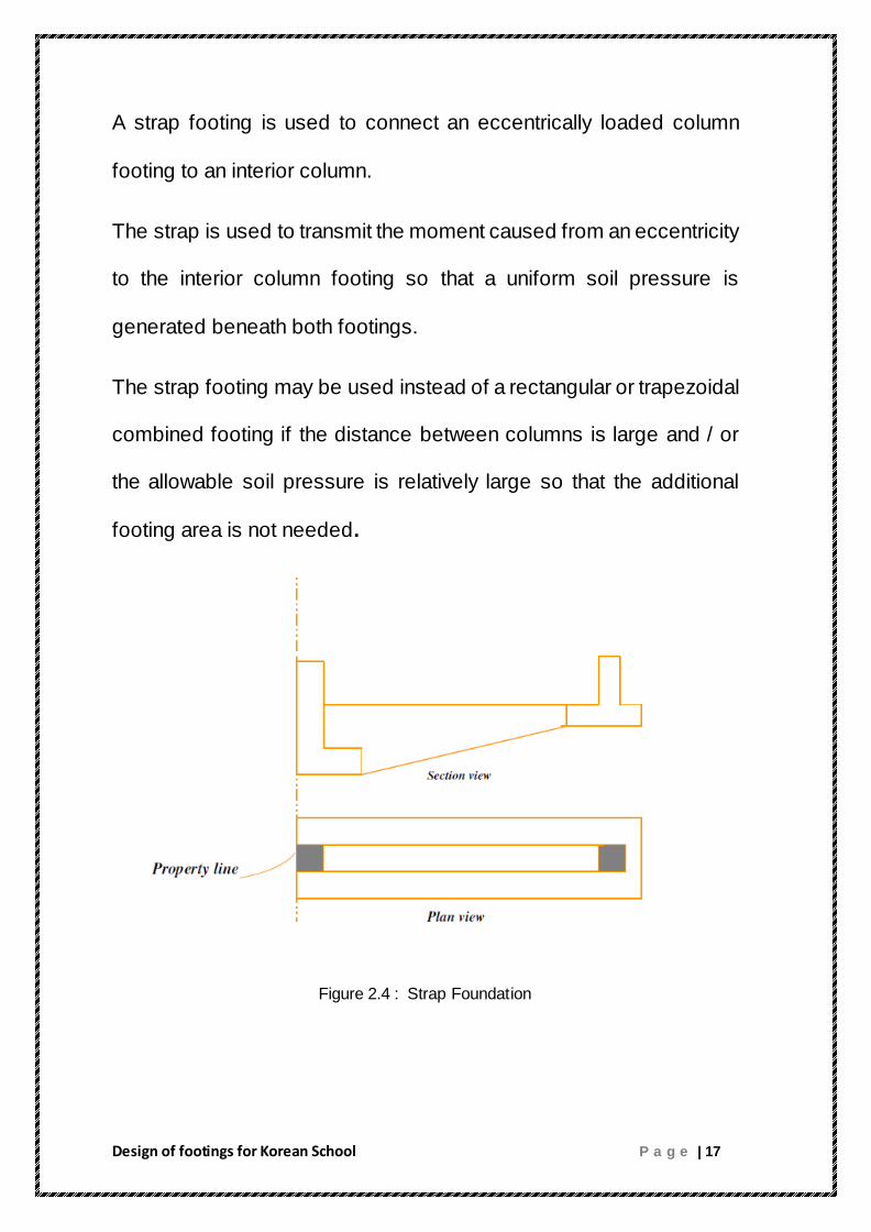
A strap footing is used to connect an eccentrically loaded column
footing to an interior column.
The strap is used to transmit the moment caused from an eccentricity
to the interior column footing so that a uniform soil pressure is
generated beneath both footings.
The strap footing may be used instead of a rectangular or trapezoidal
combined footing if the distance between columns is large and / or
the allowable soil pressure is relatively large so that the additional
footing area is not needed.
Figure 2.4 : Strap Foundation

Design of footings for Korean School P a g e | 18
2.1.3 : Continuous (Wall) Foundation
It is a continuous concrete footing under wall in all of its directions. It
is used to transmit loads from wall into soil bearing layer. This type of
footing takes the following shapes .
Figure 2.5 : Wall Footing
2.1.4 : Strip Foundation
It is one footing carrying more than two columns on longitudinal
line This type of footing is as beam calculating for it shearing force
diagram , bending moment diagram due to existing column load
and soil pressure then design it as a reinforced concrete section to
determine d and As . if the footing is concentrically loaded, the
pressure is uniform . if the column loads are not equal or not
uniformly spaced . moments of the distribution determined
assuming that the pressure varies uniformly.

Design of footings for Korean School P a g e | 19
In the longitudinal direction . the footing may be approximately
analyzed for moments and shears by either of two following
methods:
1. Assume a rigid foundation. Then the shear at any section is the
sum of the forces on the side of the section, and the moment at the
section is the sum of the moments of the forces on the side of the
section.
2. Assume the strip is an inverted continuous beam where the
columns are the support and the earth pressure causes distributed
loading.
A more accurate analysis may be made be if the flexibility of the
footing and the assumed elastic response of the soil are taken into
account . the pressure distribution will be uniform.
2.1.5 : Mat ( Raft ) Foundation
Mat foundation is a type of shallow foundation , mat foundation are a
foundation system in which essentially the entire buildings is placed
on a large continuous footing . mat foundations found some use as
early as the nineteenth century , and have continued to be utilized to
effectively resolve special soil or design conditions . in locations
where the soil is weak and bed rock is extremely deep , floating or

Design of footings for Korean School P a g e | 20
compensated mat foundations are sometimes utilized . for this type
of foundation , the amount of soil removed and the resulting uplift( on
the foundation) caused by ground water is equalized by the
downwards forces of the building and foundation. yet another
variation of the mat foundation is to use in it combination with
caissons or piles.
Mats are used to:
1- distributes loads form the periphery of the structure over the entire
are of the structure.
2- reduce concentration of high contact pressure on soil.
3- reduce hydraulic head or pressure of water.
Relative to static and strength calculations and design , mat
foundation may be classed in two broads groups.
1- Mats designed by the conventional method of analysis Rigid mats
( stiff raft).
This type is also called box structures made of cellular constructions
or rigid frames consisting of slaps and basement walls. They are
capable to resist very large flexure stresses . it is used when the

Design of footings for Korean School P a g e | 21
substructure cannot resist the different settlement developed under
of flexible raft.
2- Mats designed on the basis of the theory of elasticity.
Flexible Mats
1. Flat plate with constant thickness ( usually from 1-2m) with top and
bottom two way reinforcement steel meshes. This type is most
suitable where the column loads are small or moderate and the
column spacing is fairly small and uniform . this type is easy to be
constructed.
2. Flat plate thickened under columns , or plate with pedestals . this
type is used for large column loads to provide sufficient strength for
shear (punch) and negative moment.
3. Inverted slap with girders . it is used when the bending stresses
becomes large because of large column spacing and unequal column
loads . the disadvantages of this type is needs large amount soil
foundation depth excavation .
Some common mats foundation used.
* Flat plate with uniform thickened .
* Flat plate thickened under column .

Design of footings for Korean School P a g e | 22
* Inverted slaps with girders.
Mats sometimes supported by piles in situation such as high ground
water or where the soil is susceptible to large settlement , the piles
help in reducing the settlement of the structure located over highly
compressible soil.
Figure 2.6 : Types of Mat Foundation

Design of footings for Korean School P a g e | 23
2.2 : Deep Foundation
Deep foundations are used for heavy structures and / or weak soils. The
most common types of deep foundations is the pile foundation.
2.2.1 Pile Foundation
Pile foundations are the part of a structure used to carry and transfer
the load of the structure to the bearing ground located at some depth
below ground surface. The main components of the foundation are
the pile cap and the piles. Piles are long and slender members which
transfer the load to deeper soil or rock of high bearing capacity
avoiding shallow soil of low bearing capacity The main types of
materials used for piles are Wood, steel and concrete. Piles made
from these materials are driven, drilled or jacked into the ground and
connected to pile caps. Depending upon type of soil, pile material and
load transmitting characteristic piles are classified accordingly. In the
following chapter we learn about, classifications, functions and pros
and cons of piles.
Functions of piles
As with other types of foundations, the purpose of a pile foundations is:
To transmit a foundation load to a solid ground

Design of footings for Korean School P a g e | 24
To resist vertical, lateral and uplift load
A structure can be founded on piles if the soil immediately beneath its
base does not have adequate bearing capacity. If the results of site
investigation show that the shallow soil is unstable and weak or if the
magnitude of the estimated settlement is not acceptable a pile
foundation may become considered. Further, a cost estimate may
indicate that a pile foundation may be cheaper than any other compared
ground improvement costs.
In the cases of heavy constructions, it is likely that the bearing capacity
of the shallow soil will not be satisfactory, and the construction should
be built on
pile foundations. Piles can also be used in normal ground conditions to
resist horizontal loads. Piles are a convenient method of foundation for
works over water, such as jetties or bridge piers.
Classification of piles
Classification of pile with respect to load transmission and
functional behavior
End bearing piles (point bearing piles)
Friction piles (cohesion piles )

Design of footings for Korean School P a g e | 25
Combination of friction and cohesion piles
End bearing piles
These piles transfer their load on to a firm stratum located at a
considerable depth below the base of the structure and they derive
most of their carrying capacity from the penetration resistance of the soil
at the toe of the pile (see figure 1.1). The pile behaves as an ordinary
column and should be designed as such. Even in weak soil a pile will
not fail by buckling and this effect need only be considered if part of the
pile is unsupported, i.e. if it is in either air or water. Load is transmitted
to the soil through friction or cohesion. But sometimes, the soil
surrounding the pile may adhere to the surface of the pile and causes
"Negative Skin Friction" on the pile. This, sometimes have considerable
effect on the capacity of the pile. Negative skin friction is caused by the
drainage of the ground water and consolidation of the soil. The founding
depth of the pile is influenced by the results of the site investigate on
and soil test.
Friction or cohesion piles
Carrying capacity is derived mainly from the adhesion or friction of the
soil in contact with the shaft of the pile.

Design of footings for Korean School P a g e | 26
Figure 2.7 : End Bearing Pile
Friction or cohesion piles
Carrying capacity is derived mainly from the adhesion or friction of
the soil in contact with the shaft of the pile .
Cohesion piles
These piles transmit most of their load to the soil through skin
friction. This process of driving such piles close to each other in
groups greatly reduces the porosity and compressibility of the soil
within and around the groups. Therefore piles of this category are
sometimes called compaction piles. During the process of driving
the pile into the ground, the soil becomes molded and, as a result
loses some of its strength. Therefore the pile is not able to transfer
the exact amount of load which it is intended to immediately after it

Design of footings for Korean School P a g e | 27
has been driven. Usually, the soil regains some of its strength three
to five months after it has been driven.
Friction piles
These piles also transfer their load to the ground through skin
friction. The process of driving such piles does not compact the soil
appreciably. These types of pile foundations are commonly known as
floating pile foundations.
Figure 2.8 : Friction Piles
Combination of friction piles and cohesion piles
An extension of the end bearing pile when the bearing stratum is not
hard, such as a firm clay. The pile is driven far enough into the lower
material to develop adequate frictional resistance. A farther variation

Design of footings for Korean School P a g e | 28
of the end bearing pile is piles with enlarged bearing areas. This is
achieved by forcing a bulb of concrete into the soft stratum
immediately above the firm layer to give an enlarged base. A similar
effect is produced with bored piles by forming a large cone or bell at
the bottom with a special reaming tool. Bored piles which are
provided with a bell have a high tensile strength and can be used as
tension piles.
Figure2.9 : Combination of Friction and Cohesion Piles
Classification of pile with respect to type of material
Timber Concrete Steel Composite piles
Factors affecting choice of pile
Location and type of structure.

Design of footings for Korean School P a g e | 29
Ground conditions.
Durability.
Cost.
There are many factors that can affect the choice of a piled foundations.
all factors need to be considered and their relative importance taken
into account before reaching a final decision .
2.3 : Special Foundation
Foundation for tall structure (smoke stacks , radio and television
towers , light houses )
Foundation for subsurface and overland pipe lines.
Foundation for port and maritime structures .
Machine foundation.
Vehicular and aqueous tunnels .
Foundation on elastic support.
Other foundation of elastic support.

Design of footings for Korean School P a g e | 30
2.4 : General Capacity of Soils
Bearing Capacity is the ability of a soil to support a load from
foundation without causing a shear failure or excessive settlement.
The sign of Bearing Capacity (B.C) and this units as pressure's unit
ton/m2, KN/ m
2, Kg/cm
2, lb/ft
2 etc… so can called Bearing Pressure.
Its known from observation of foundation subjected to load bearing
capacity failure occurs usually as shear failure of the soil supporting
the footing .the three principles modes of shear under foundation
have been as general shear failure . local shear failure , and
punching shear failure.
Consider a strip foundation resting on the surface of a dense or
stiff cohesive soil , as shown in the figure ( 2.12 ) , with a width
of B now, if the load is gradually applied to the foundation ,
settlement will increase.
the variation the load per unit area on the foundation , q , with
the foundation settlement is al so shown in figure( 2.10) .At the
certain point when the load per unit area equals qu a sudden
failure in the soil supporting the foundation will occur and the
failure in the soil will extend to the ground surface. This load
per unit area ,qu , is usually referred to as the ultimate bearing
capacity of the foundation . when this type of sudden failure
takes place , it is called d the general shear failure.
If the foundation under consideration rest on sand or clays soil
of medium compaction figure (2.9), an increase of load on
foundation will be also accompanied by an increase of
settlement, however , in this case the failure in the soil will
Design of footings for Korean School P a g e | 31
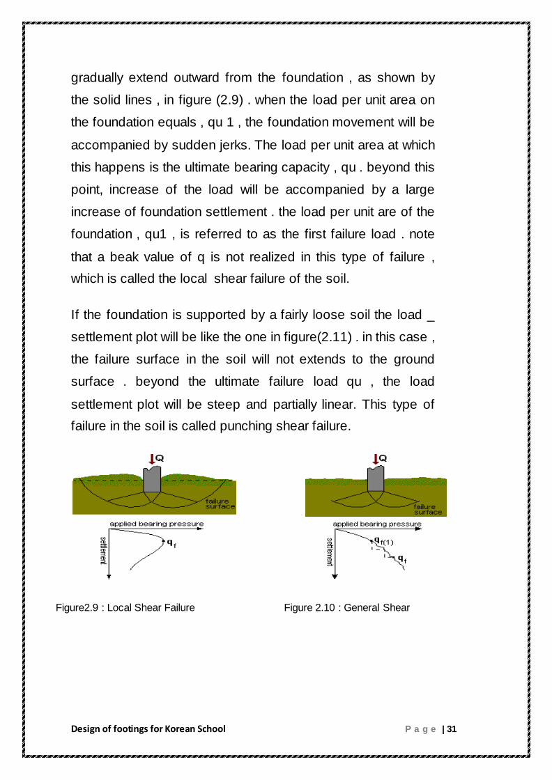
gradually extend outward from the foundation , as shown by
the solid lines , in figure (2.9) . when the load per unit area on
the foundation equals , qu 1 , the foundation movement will be
accompanied by sudden jerks. The load per unit area at which
this happens is the ultimate bearing capacity , qu . beyond this
point, increase of the load will be accompanied by a large
increase of foundation settlement . the load per unit are of the
foundation , qu1 , is referred to as the first failure load . note
that a beak value of q is not realized in this type of failure ,
which is called the local shear failure of the soil.
If the foundation is supported by a fairly loose soil the load _
settlement plot will be like the one in figure(2.11) . in this case ,
the failure surface in the soil will not extends to the ground
surface . beyond the ultimate failure load qu , the load
settlement plot will be steep and partially linear. This type of
failure in the soil is called punching shear failure.
Figure2.9 : Local Shear Failure Figure 2.10 : General Shear

Design of footings for Korean School P a g e | 32
Figure 2.11 : Punching Shear
Factors affecting modes of failure
According to experimental results from foundation resting on sand ,
the mode of failure likely to occur in any situation depends on the
size of the foundation and the relative density of the soil.
Other factors might be:
Permeability : relating to drained / untrained behavior
compressibility.
Shape e.g. strips can only rotates one way.
Interaction between adjacent foundations and other
structures.
Incidence and relative magnitude of horizontal loading or
moments.
Presence of stiffer or weaker underlying lyres.

Design of footings for Korean School P a g e | 33
2.4.1 : Terzaghi’s Bearing Capacity Theory
In 1948, Terzaghi proposed a well-conceived theory to
determine the ultimate bearing capacity
of a shallow rough rigid continuous (strip) foundation supported by a
homogeneous soil layer extending to a great depth. Terzaghi defined
a shallow foundation as a foundation where the width, B, is equal to
or less than its depth, Df . The failure surface in soil at ultimate load
(that is, qu , per unit area of the foundation) assumed by Terzaghi is
shown in Fig. Referring to Fig, the failure area in the soil under the
foundation can be divided into three major zones. They are:
1. Zone ACD This is a triangular elastic zone located immediately
below the bottom of the foundation. The inclination of sides AC and
BC of the wedge with the horizontal is " = N (soil friction angle).
2. Zone ADF. and CED This zone is the Prandtl’s radial shear
zone.
3. Zone AFH and CEG. This zone is the Rankine passive zone. The
slip lines in this zone make angles of ±(45 - N/2) with the horizontal.

Design of footings for Korean School P a g e | 34
Figure 2.13 : Bearing capacity failure in soil under a rough rigid continuous footing
Note that the replacement of the soil above the bottom of the
foundation by an equivalent surcharge q, the shear resistance
of the soil along the failure surface GI and HG was neglected.
Using the equilibrium analysis Terzaghi expressed the ultimate
bearing capacity in the form.
(Strip Foundation) (2.1)
Where c= cohesion of soil
= unit weight of soil
Q= Df

Design of footings for Korean School P a g e | 35
where Nc , Nq , and N = bearing capacity factors that are non
dimensional and they are only functions of the soil friction
angle , the bearing capacity factors are defined by:
For foundations that are rectangular or circular in plan, a plane strain
condition in soil at ultimate load does not exist. Therefore, Terzaghi
proposed the following relationships for square and circular
foundations.
Square footings:
Circular footings:
It is obvious that Terzaghi’s bearing capacity theory was
obtained by assuming general shear failure in soil. However,
the local shear failure in soil, Terzaghi suggested the following
relationships:
´´ ´ strip foundation (2.7)
´ ´ ´ square foundation (2.8)
´´ ´ circular foundation (2.9)

Design of footings for Korean School P a g e | 36
2.4.2 General Bearing Capacity Equation
The ultimate bearing capacity equations presented are for
continuous , square , and circular foundation only . They do not
address the case of rectangular foundations (0<B/L<1) . Also , the
equations do not take into account the shearing resistance along the
failure surface in soil above the bottom of the foundation of the
failure surface marked as GI and HJ . In addition , the load on the
foundation may be inclined. To account for all these shortcomings ,
Meyerhof (1963) suggested the following form bearing capacity
equation.
(2.10)
Where
C= cohesion.
q= effective stresses at level of the bottom of the foundation.
=soil unit weight.
B= width or diameter for circular foundation.
Fcs, Fqs, Fs = shape factors.
Fci, Fqi, F i = load inclination factor.
Fcd , Fqd , Fd = depth factors.

Design of footings for Korean School P a g e | 37
Note that the original equation for ultimate bearing capacity
equation is derived only for the plane – strain case ( that is , for
continuous foundation) . the shape , depth and load inclination
factors based on experimental data.
2.4.3 : Bearing Capacity Factors
Based on laboratory and field studies of bearing capacity , the basic
of the failure surface in soil suggested by Terzaghi now appears to
be correct ( Vesic , 1973). However , the angle α is closer to 45+ .
if this change is accepted , the value of Nc , Nq , and N for a given
soil friction angle will also change from those give with α = 45+/2 ,
the relations for Nc , Nq can be derived as
(2.11)
(2.12)
The relation for Nq was presented by Reissner (1924) Caquot .
Kersal (1953) and Vesic (1973) gave the relation for N as
(2.13)

Design of footings for Korean School P a g e | 38
Table shows the variation of the proceeding bearing capacity
factors with soil friction angle.
Table 2.1 : Bearing Capacity Factors

Design of footings for Korean School P a g e | 39
The relationship for shape. Depth and inclination factors,
recommended for uses are shown in table other relationships
generally found in many texts and references.
Table 2.2 : Shape depth and inclination factors

Design of footings for Korean School P a g e | 40
2.5 : Soil Settlement
In design of most foundations, there are specifications for
allowable levels of settlement. Refer to Fig.(2.3) which is a plot
of load per unit area q versus settlement S for a foundation.
The ultimate bearing capacity is realized at a settlement level
of Su. Let Sall be the allowable level of settlement for the
foundation and qall(S) be the corresponding allowable bearing
capacity. If FS is the factor of safety against bearing capacity
failure, then the allowable bearing capacity is qall (b) = qu /FS.
Figure 2.14 : Load settlement curve for shallow foundation
The settlement corresponding to qall (b) is S´. For foundations with
smaller widths of B, S´ may be less than Sall ; however, for larger
values of B, Sall < S´. Hence, for smaller foundation widths, the
bearing capacity controls and, for larger foundation widths, the

Design of footings for Korean School P a g e | 41
allowable settlement controls. This section describes the procedures
for estimating the settlement of foundations under load.
2.5.1 : Total and Differential Settlements
Settlement due to consolidation of the foundation soil is usually the
most important consideration in the calculating the serviceability limit
state or in assessing allowable bearing pressers where permissible
stress methods are used.
Even though sinking of foundation as a result of shear failure of the
soil been safeguarded by ultimate limit state calculations or by
applying arbitrary safety factor.
on the calculated ultimate bearing capacity, it is still necessary to
investigate the likelihood of settlements before the allowable bearing
pressure can be fixed. In the following pages consideration will be
given to the causes of settlement, the effects on the structure of total
and differential settlement, methods of estimating settlement, and the
design of the foundation to eliminate settlement or to minimize its
effects.
Any structure built on soil is subject to settlement. Some settlement
is inevitable and, depending on the situation, some settlements are
tolerable. When building structures on top of soils, one needs to
have some knowledge of how settlement occurs and predict how
much and how fast settlement will occur in a given situation.
Important factors that influence settlement:
Soil Permeability
Soil Drainage

Design of footings for Korean School P a g e | 42
Load to be placed on the soil
History of loads placed upon the soil (normally or over-
consolidated)
Water Table
Settlement is caused both by soil compression and lateral yielding
(movement of soil in the lateral direction) of the soils located under
the loaded area. Cohesive soils usually settle from compression
while cohesion less soils often settle from lateral yielding - however,
both factors may play a role. Some other less common causes of
settlement include dynamic forces, changes in the groundwater
table, adjacent excavations, etc. Compressive deformation generally
results from a reduction in the void volume, accompanied by the
rearrangement of soil grains. The reduction in void volume and
rearrangement of soil grains is a function of time. How these
deformations develop with time depends on the type of soil and the
strength of the externally applied load (or pressure). In soils of high
permeability (e.g. coarse-grained soils), this process requires a short
time interval for completion, and almost all settlement occurs by the
time construction is complete. In low permeable soils (e.g. fine-
grained soils) the process occurs very slowly. Thus, settlement takes
place slowly and continues over a long period of time. In essence, a
graph of the void ratio as a function of time for several different
applied loads provides an enormous amount of information about the
settlement characteristics of a soil.

Design of footings for Korean School P a g e | 43
2.5.2 : Types of Settlements
The settlement of a structural foundation consists of three
parts:
1. The immediate settlement (ρi) this settlement takes place during
application of loading as a result of elastic deformation of the soil
without change in water content.
2. The consolidation settlement (ρc) this settlement takes place as a
result of volume reduction of the soil caused by extrusion of
some of the pore water from the soil.
3. The Creep or secondary settlement (ρα) this settlement
occurs over a very long period of years after completing
the extrusion of excess pore water. It’s caused by the
viscous resistance of the soil particle to adjustment under
compression.
4. the final settlement (ρf) this settlement is the sum of the (ρi)
and (ρα)
If deep excavation is required to reach the foundation
level, swelling of the soil will take place as a result of
removal of the pressure of the overburden. The magnitude
of the swelling is depending on the depth of overburden
removed and the time of foundations remains unloaded.

Design of footings for Korean School P a g e | 44
2.5.3 Estimation of Settlement of Foundation on Sand and
Gravels
Settlements of foundation on sand, gravel and granular fill materials,
takes place almost immediately as the foundation loading is imposed
on them. Because of the difficulty of sampling these soils, there is no
practicable laboratory test procedure for determining their
consolidation characteristics.
From a review of a number of case records of the settlement of
structures founded on these soils, Sutherland concluded that there is
no reliable method for extrapolating the settlement of a standard
plate to the settlement of an actual foundation at the same location.
Consequently settlements of foundations on sand and gravel are
estimated by semi-empirical method based on SPT or CPT values or
on the results of pressure meter test. There are many tests to
calculate the value of settlement in sand and gravel
1. Estimation of settlement from standard penetration tests
2. Estimation of settlement from static cone penetration tests
3. Estimation of settlement from pressure meter tests
* Estimation of settlement from standard penetration tests
Berland and Burbidge establish an empirical relationship based on
the standard penetration test from which the settlement of foundation
on sand and gravel can be calculated from the equation

Design of footings for Korean School P a g e | 45
2.5.4 Calculation of Secondary Consolidation Settlement
1) Secondary consolidation is the portion of time-dependent
settlement that occurs at essentially constant effective stress.
2) The rate of secondary consolidation is not dependent on the flow
of water or on clay layer thickness, and is relatively constant for
normal engineering stress increases.
3) Secondary consolidation occurs slowly with a continually
decreasing rate.
4) The secondary consolidation portion of the consolidation curve is
approximately linear on an e-log time plot.
5) Secondary consolidation usually estimated from a lab
consolidation test.
6) The exact cause of secondary consolidation is unknown, but is
possibly a readjustment of the double water layer surrounding the
clay particles.
7) Secondary consolidation may be more important than primary
consolidation for organic and highly compressible inorganic clays.
8) The ratio of secondary to primary consolidation increases as the
ratio of stress increment to initial stress decreases: i.e. watch out for
small stress increases in thick clay layers.

Design of footings for Korean School P a g e | 46
2.5.5 Settlement of Piles
The elastic settlement of a pile under a vertical working load, Qw , is
determined by three factors :
Se=Se(1)+Se(2)+Se(3) (2.14)
Where Se = the total settlement in the pile
Se (1) = settlement of pile shaft
Se (2) = settlement of pile caused by the load at the pile point
Se (3) = settlement of pile caused by the load transmitted along
the pile shaft
Determination of Se (1)
If the pile material is assumed to be elastic, the deformation of the
pile shaft can be evaluated using the fundamental principles of
mechanics of materials:
PP
wswp
eEA
LQQS
)()1(
(2. 15)
Where Qwp = load carried at the pile point under working load
condition
Qws = load carried by frictional (skin) resistance under working
load condition
AP = area of the pile cross section
L = length of the pile
Ep = modulus of elasticity of the pile material
Design of footings for Korean School P a g e | 47
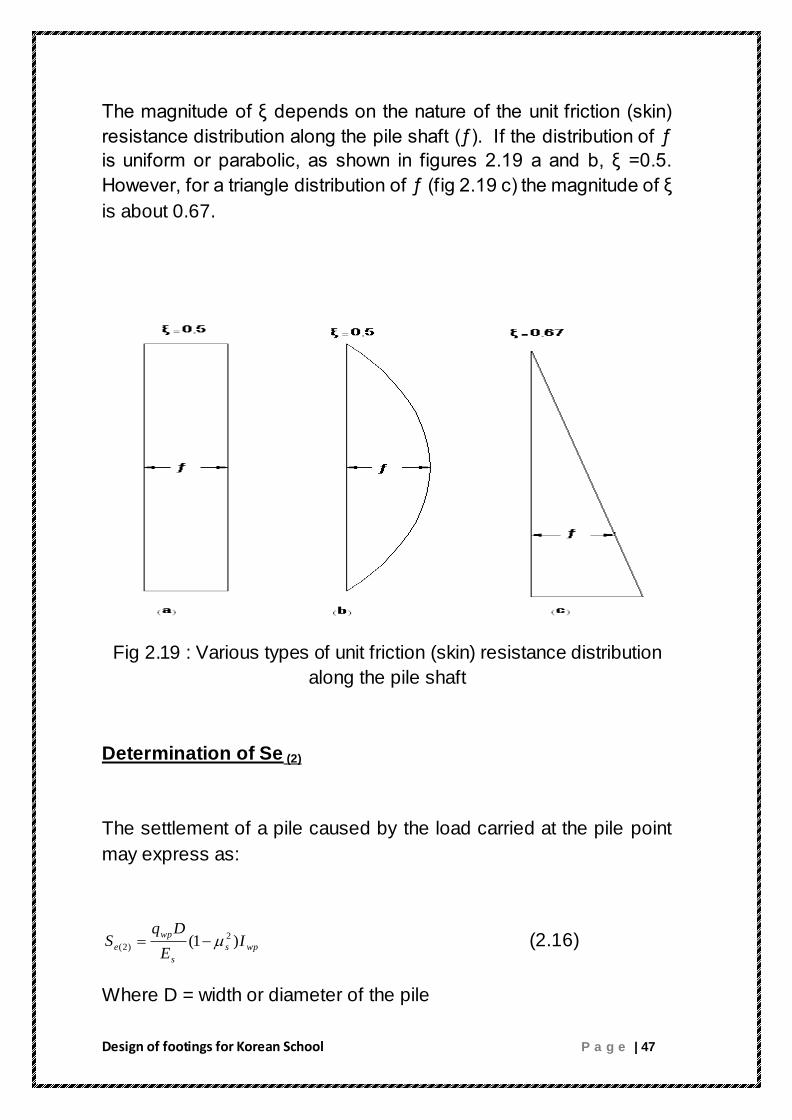
The magnitude of ξ depends on the nature of the unit friction (skin)
resistance distribution along the pile shaft (ƒ). If the distribution of ƒ
is uniform or parabolic, as shown in figures 2.19 a and b, ξ =0.5.
However, for a triangle distribution of ƒ (fig 2.19 c) the magnitude of ξ
is about 0.67.
Fig 2.19 : Various types of unit friction (skin) resistance distribution
along the pile shaft
Determination of Se (2)
The settlement of a pile caused by the load carried at the pile point
may express as:
wps
s
wp
e IE
DqS )1( 2
)2( (2.16)
Where D = width or diameter of the pile
Design of footings for Korean School P a g e | 48
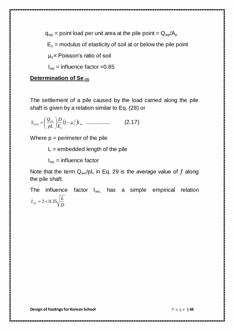
qwp = point load per unit area at the pile point = Qwp/Ap
Es = modulus of elasticity of soil at or below the pile point
μs= Poisson’s ratio of soil
Iwp = influence factor =0.85
Determination of Se (3)
The settlement of a pile caused by the load carried along the pile
shaft is given by a relation similar to Eq. (28) or
wss
s
wse I
E
D
pL
QS 2
)3( 1
................ (2.17)
Where p = perimeter of the pile
L = embedded length of the pile
Iws = influence factor
Note that the term Qws/pL in Eq. 29 is the average value of ƒ along
the pile shaft.
The influence factor Iws, has a simple empirical relation
D
LIws 35.02

Design of footings for Korean School P a g e | 49
CHAPTER THREE
DESIGN AND CALCULATION
3.1 Calculation of loads on columns
Density :
Sand = 1.6t/m 3̂
Mortar and tiles = 2.5t/m 3̂
Concrete = 2.5t/m 3̂
Hollow block = 1.2t/m 3̂
Plaster = 2.5t/m 3̂
Ru = 0.52cm 2̂
For calculated wu :
* Mortar and tiles = (0.05*2.5*0.52*1) = 0.065 t/Ru
* sand = (0.1*1.6*0.52*1) = 0.0832 t/Ru
* hollow block =( 0.4*0.17*1.2**1) = 0.0816 t/Ru
*concrete = ((0.08*0.52)+(0.12*0.17))*2.5*1 = 0.155 t/Ru
* plaster = (0.02*2.5*0.52*1) = 0.026 t/Ru
*∑ = 0.4108 t/Ru
→ for (1m) = 0.4108/0.52= 0.79t/m 2̂
DL = portioning+ material load
= 0.125+0.79 = 0.915 t/m 2̂
L.L = 0.3t/m 2̂ for class room
L.L = 0.5t/m 2̂ for corridors

Design of footings for Korean School P a g e | 50
Wu for class room
Wu = (1.2*0.915)+(1.6*0.3) = 1.578t/m 2̂
Wu = (1.2*0.915)+(1.6*0.5) = 1.898t/m 2̂
* For column one
(1.35*1.6*1.578*4)+((0.25*1.04*2.5*1.6*4)+(1.6*0.2*1.2*16.2)+
(0.1*1.6*17*2.5)+(1.35*0.25*1.04*2.5*4)+(1.35*16.2*0.2*1.2)+
(0.3*0.5*16.2*2.5)+(0.1*1.35*17*2.5))*1.2= 57.86ton
* for column two
(4.725*2.7*1.578*4) +((2.7*0.25*1.04*2.5*4)+(4.725*0.25*0.7*4*2.5)
+ (2.7*0.2*16.2*1.2)+(0.1*2.7*17*2.5)+(0.3*0.5*16.2*2.5)+(0.02*2.7*
16.2*2.5))*1.2 = 132.5 ton
* for column three
(2.7*3.125*1.578*4)+((2.7*0.25*1.04*4*2.5)+(3.125*0.25*0.74*2.5)
+(0.2*2.7*16.2*1.2)+(0.1*2.7*17*2.5)+(0.02*2.7*13.76*2.5)+
(0.02*2*3.125*13.76*2.5)+(0.3*0.25*16.2*2.5)+(0.3*0.25*17*2.5))*
1.2 = 105 ton

Design of footings for Korean School P a g e | 51
3.2 Design of Footings
We designed footings as combined when we look to the allowable
bearing capacity of the soil we find that it is moderate and the design
of combined footing is possible and more economical than others,
and those footings two of it has two columns and it designed
manually, but the rest has many of columns and it designed by using
SAP program .
3.2.1 Design of combined footings
This footing has two coulmns and it designed manually as shown
below
Q1 = 39.28 ton
Q2=39.28 ton
L3= 3.35 m
Area = (Q1+Q2)/ qall

Design of footings for Korean School P a g e | 52
Area = ( 39.28 + 39.28 ) / 20
:. Area = 3.93 m2
Take moment at A :
39.28 * 3.35 = (Q1+Q2) * X
:. X = 1.675 m
L = ( 1.675 + .25 ) * 2
L = 3.85 + .55 = 4.4
:. L= 4.4 m
B = 3.93/4.4
B= .89
:. B= 1 m
:. L2=L1=.525 m

Design of footings for Korean School P a g e | 53
Punching Shear :
41.88 – 25 *(.25 +d ) = Vu
0.75 *0.35 *√240 * 10 *10 * 1* d = Vc
Vu = Vc
d = 41 cm
h =50 cm

Design of footings for Korean School P a g e | 54
Checking Punching shear :
C#1 :
Pup= 55 – 25 ( 0.5 + 0.41/2 ) * ( 0.5 + 0.41 )
= 46 .98
Vc= 0.75 * 1.06 *√ 240 * 10 * ( 2 ( 0.5 + 0.41/2 ) + 0.5 + 0.41 ) ) *
0.41
117.15 > 46.98 so it’s ok
C#2 :
The same calculation for C#1
Design of flexure :
Mu= 31.63
ρ=.85*240/4200(1-√(1-(2.61*105*31.63 /100*41
2*240)
=5.25*10-3
ρ min =14/fy =14/4200=3.33*10-3
ρ > ρ min

Design of footings for Korean School P a g e | 55
:. Use ρ
As = ρ * b * d
As = 21.525 cm 2
:. Use 11 16
Bottom steel
Mu = 3.44
ρ=.85*240/4200(1-√(1-(2.61*105*3.44 /100*41
2*240) =5.43*10
-4
ρ min =14/fy =14/4200=3.33*10-3
ρ < ρ min
:. Use ρ min
As = ρ * b * d
As = 13.53 cm2
:. Use 7 16
As shrinkage = 0.0018 * 100 * 40
= 9 cm2
:. Use Stirrup 11 16
Design of footings for Korean School P a g e | 56
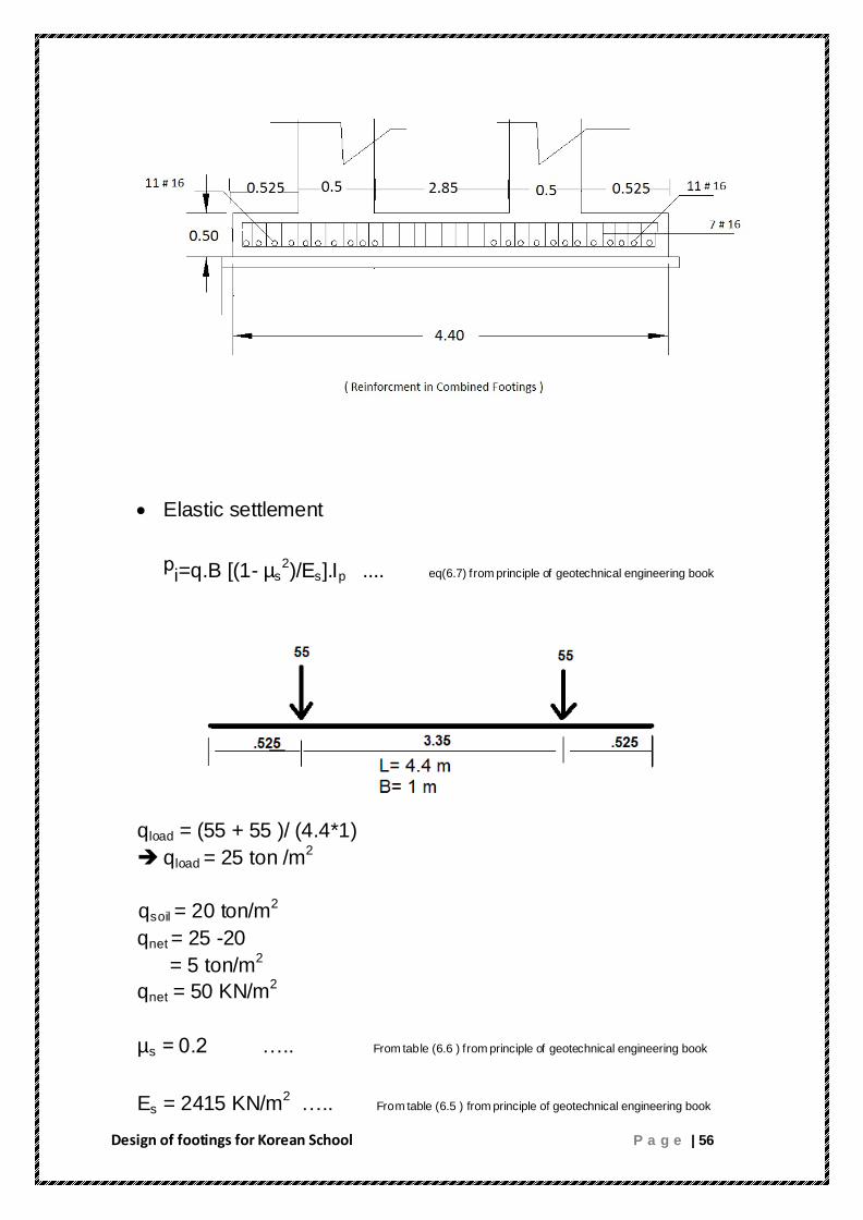
Elastic settlement
ᵖi=q.B [(1- µs2)/Es].Ip .... eq(6.7) from principle of geotechnical engineering book
qload = (55 + 55 )/ (4.4*1)
qload = 25 ton /m2
qsoil = 20 ton/m2
qnet = 25 -20
= 5 ton/m2
qnet = 50 KN/m2
µs = 0.2 ….. From table (6.6 ) from principle of geotechnical engineering book
Es = 2415 KN/m2 ….. From table (6.5 ) from principle of geotechnical engineering book

Design of footings for Korean School P a g e | 57
Ip = 2 ….. From table (6.4 ) from principle of geotechnical engineering book
from eq (6.7)
ᵖi = 0.039 m
The calculated settlement is considered high .In order to reduce
this value, certain measures can be undertaken including soil
improvement by various methods. These methods may be soil
excavation and replacement of better soil, soil stabilization by
compaction and other methods .

Design of footings for Korean School P a g e | 58
3.2.2 Design of Combined footings (continuos)
The following footings has several coulmns and it designed by
using SAP program to analysis and design all of the combined
footings below .
A. Combined Footing ( F2 )
Area of footings = 798.2/20
Area = 39.91 m2
MA=0
41.3*27 + 94.6*24.3 +94.6*21.6 +75.2*18.9+75.2*16.2
+75.2*13.5 +75.2*10.8 +75.2*8.1+75.2*5.4 +75.2*2.7 = 798.2 * x
11142.36 = 798.2 * x
:. X = 13.96 m
:. L = (13.96 + 0.125 )*2
L = 28.17 m
:. Take L = 28.5 m

Design of footings for Korean School P a g e | 59
B = Area / L
B = 39.91/28.5
:. B = 1.4 m
Punching Shear :
The same calculations as combined footing before :
Vu = Vc
d = 41 cm
h =50 cm
Design of flexure :
Bottom Steel
From SAP :
For Column # 60 & # 61

Design of footings for Korean School P a g e | 60
Mu = 60 t.m
ρ=.85*240/4200(1-√(1-(2.61*105*60 /100*41
2*240) =10.5 *10
-3.
ρ min =14/fy =14/4200=3.33*10-3
ρ > ρ min
Use ρ
As = ρ * b * d
As = 0.0105 * 140 * 41
As = 60.27 cm2
:. Use 13 25
For other columns :
Mu = 32 t.m
ρ=.85*240/4200(1-√(1-(2.61*105*32 /100*41
2*240) =5.26 *10
-3
ρ min =14/fy =14/4200=3.33*10-3
ρ > ρ min
Use ρ
As = ρ * b * d
As = 0.00526 * 140 * 41
As = 30.2 cm2
:. Use 10 20
Top Steel
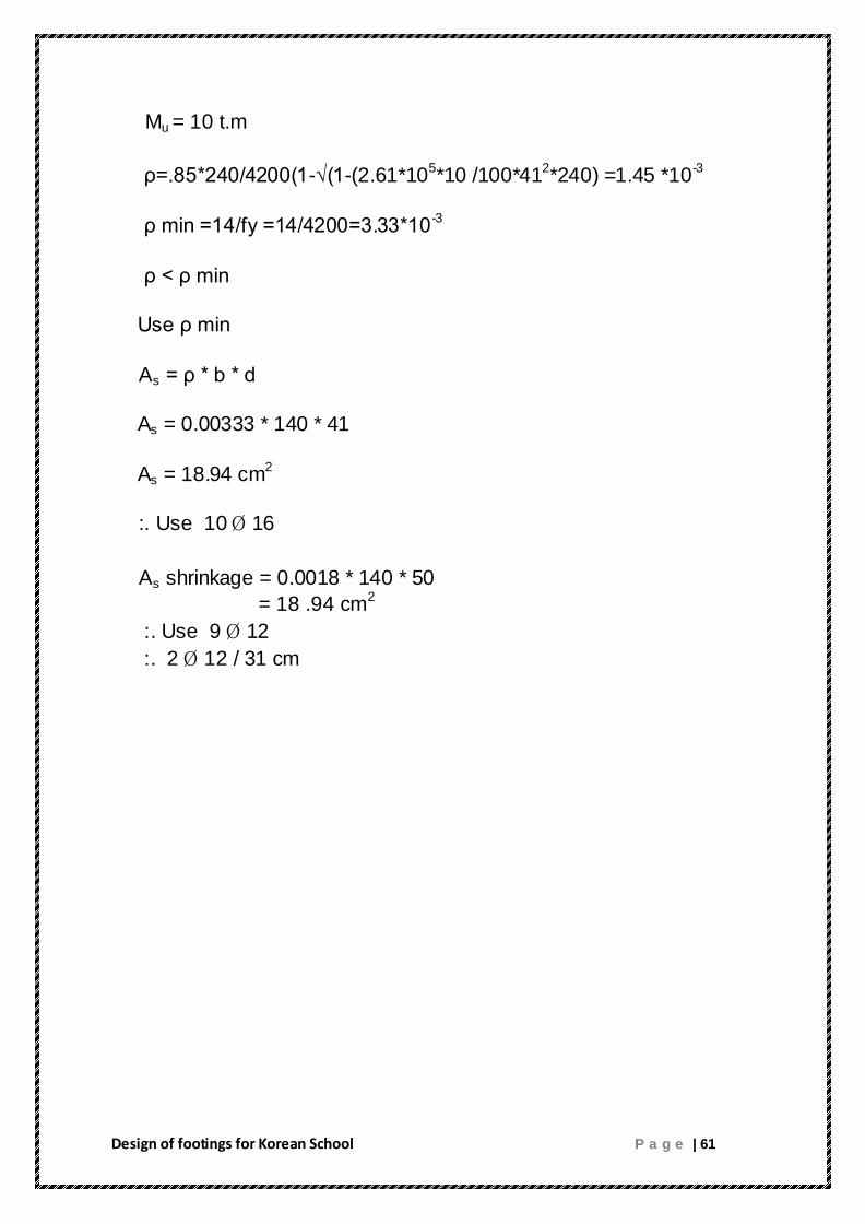
Design of footings for Korean School P a g e | 61
Mu = 10 t.m
ρ=.85*240/4200(1-√(1-(2.61*105*10 /100*41
2*240) =1.45 *10
-3
ρ min =14/fy =14/4200=3.33*10-3
ρ < ρ min
Use ρ min
As = ρ * b * d
As = 0.00333 * 140 * 41
As = 18.94 cm2
:. Use 10 16
As shrinkage = 0.0018 * 140 * 50
= 18 .94 cm2
:. Use 9 12
:. 2 12 / 31 cm

Design of footings for Korean School P a g e | 62
B. Combined Footing ( F1 )

Design of footings for Korean School P a g e | 63
Area of footings = 672.2/20
Area = 31.36 m2
MA=0
41.3*21.6 + 94.6*18.9 +75*16.2 +75*13.5+75*10.8 +75*8.1
+75*5.4 +75*2.7 = 627.2 * x
6932.52 = 627.2 * x
:. X = 11.05 m
:. L = (11.05 + 0.125 )*2
L = 22.35 m
:. Take L = 23 m
B = Area / L
B = 31.63/23
:. B = 1.4 m

Design of footings for Korean School P a g e | 64
Punching Shear :
The same calculation as combined footing before :
Vu = Vc
d = 41 cm
h =50 cm
Design of flexure :
Bottom Steel
From SAP :
For Column 2
Mu = 64 t.m
ρ=.85*240/4200(1-√(1-(2.61*105*64 /100*41
2*240) =11 *10
-3
ρ min =14/fy =14/4200=3.33*10-3
ρ > ρ min
Use ρ
As = ρ * b * d
As = 0.011 * 140 * 41
As = 63.14 cm2
:. Use 13 25
For other columns :
Mu = 31 t.m
ρ=.85*240/4200(1-√(1-(2.61*105*31 /100*41
2*240) =5.25 *10
-3

Design of footings for Korean School P a g e | 65
ρ min =14/fy =14/4200=3.33*10-3
ρ > ρ min
Use ρ
As = ρ * b * d
As = 0.00525 * 140 * 41
As = 30.13 cm2
:. Use 10 20
Top Steel
Mu = 9 t.m
ρ=.85*240/4200(1-√(1-(2.61*105*9 /100*41
2*240) =1.43 *10
-3
ρ min =14/fy =14/4200=3.33*10-3
ρ < ρ min
Use ρ min
As = ρ * b * d
As = 0.00333 * 140 * 41
As = 18.94 cm2
:. Use 10 16
As shrinkage = 0.0018 * 140 * 50
= 18 .94 cm2
:. Use 9 12
:. 2 12 / 31 cm
Design of footings for Korean School P a g e | 66
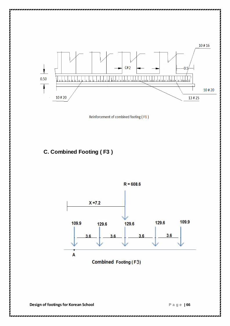
C. Combined Footing ( F3 )

Design of footings for Korean School P a g e | 67
Area of footings = 608.6/20
Area = 30.43 m2
MA=0
109.9*14.4 + 129.6*10.8 +129.6*7.2 +129.6*3.6 = 608.6 * x
:. X = 7.2 m
:. L = (7.2 + 0.125 )*2
L = 14.65 m
:. Take L = 15.5 m
B = Area / L
B = 30.43/15.5
:. B = 2 m

Design of footings for Korean School P a g e | 68
Punching Shear :
The same calculation as combined footing before :
Vu = Vc
d = 41 cm
h =50 cm
Design of flexure :
Bottom Steel
From SAP :
For Column 32
Mu = 64 t.m
ρ=.85*240/4200(1-√(1-(2.61*105*64 /100*41
2*240) =11 *10
-3
ρ min =14/fy =14/4200=3.33*10-3
ρ > ρ min
Use ρ
As = ρ * b * d
As = 0.011 * 200 * 41
As = 90.2 cm2
:. Use 19 25
For other columns :
Mu = 45 t.m
ρ=.85*240/4200(1-√(1-(2.61*105*45 /100*41
2*240) =7.67 *10
-3

Design of footings for Korean School P a g e | 69
ρ min =14/fy =14/4200=3.33*10-3
ρ > ρ min
Use ρ
As = ρ * b * d
As = 0.00767 * 200 * 41
As = 62.89 cm2
:. Use 13 25
Top Steel
Mu = 33 t.m
ρ=.85*240/4200(1-√(1-(2.61*105*33 /100*41
2*240) =5.49 *10
-3
ρ min =14/fy =14/4200=3.33*10-3
ρ > ρ min
Use ρ
As = ρ * b * d
As = 0.00549 * 200 * 41
As = 45.01 cm2
:. Use 15 16
As shrinkage = 0.0018 * 200 * 50
= 18 cm2
:. Use 16 12
:. 2 12 / 31 cm

Design of footings for Korean School P a g e | 70

Design of footings for Korean School P a g e | 71
3.3 Design of Shear wall :
The ultimate axial load on walls is from the loads from
adjoining slab ( dead & live load ) , reactions of beams , in
addition to own weight of wall .
Wbeam = 0.25 *0.70 * 8.2 * 2.5
= 3.5875 ton
Load on shear wall ( SH1 ) “ Pu “
Pu = ( 1.755 *1.8 *8.2 *0.25 * 4 ) + ( 3.58 75 *4 ) *1.2 + 1.2*
(0.02 * 2.5 *8.2 * 16.2) + 1.85 * 0.25 * 6.90 * 1.775 + 1.2*(
0.02 * 1.85 *6.9 * 2.5 *16.8 )
Pu = 70 ton
According to ACI cpde (14.5 )
Pnw = 0.55 f’c Ag [ 1 – ( K Lc / 32 h )
2 ]
Pnw : nominal axial load strength of wall .
Ag : gross area of section .
h : over all thickness of member .
: strength reduction factor which equal ( 0.7 )
Lc : vertical distance between supports .
K : effective length factor , which less than 1 , conservatively
we will consder that K
=1
Pnw = 0.55 f’c Ag [ 1 – ( K Lc / 32 h )
2 ]
Pnw = 0.55 * 0.7 * 240 *( 6.9 * 0.3 ) * [ 1 – ( 4 / 32 * 0.3 )2 ]

Design of footings for Korean School P a g e | 72
=158.06 ton > 70 ton so it’s safe
Vertical reinforcement :
According to ACI code ( 14.3.2) minimum ratio of vertical
reinforcement area to gross concrete area shall be 0.0012
As = ρ * b * d
As = 0.0012 * 100 * 30
As = 3.6 cm2
:. Use 14 / 40 cm
Horizontal reinforcement :
According to ACI code ( 14.3.3) minimum ratio of horizontal
reinforcement area to gross concrete area shall be 0.002
As = ρ * b * d
As = 0.002 * 100 * 30
As = 6 cm2
:. Use 14 / 25 cm

Design of footings for Korean School P a g e | 73

Design of footings for Korean School P a g e | 74
3.4 Design of a Retaining wall :

Design of footings for Korean School P a g e | 75
H’= 4+0.4+1.8 tan 10
0 = 4.68 m
From table Active earth pressure coefficient Ka
α = 10o , = 30
o
Ka = 0.35
Pa = 0.5 * H’2 * γ * Ka
Pa = 0.5 4.682 * 18 * 0.35
Pa = 68.99 KN/m
Pv = Pa * sin 10o
Pv = 11.97 KN/m
Ph = Pa * cos 10o
Ph = 67.94 KN/m
From the figure “ Retaining wall “ on the previous page , the cont.
calcualtions as shown in the table below :
Section No. Area
Weight/ Unit length (KN/m)
Moment Arm point C Moment (KN.m/m)
1 1.2 30 0.65 19.5 2 0.2 5 0.466 2.33
3 1.64 24 1.3 28.8 4 7.2 115.2 1.8 184.32
5 0.224 4.03 1.86 7.49
Pv = 11.97
R

Design of footings for Korean School P a g e | 76
The Overturning moment :
Mo = Ph * ( H’/ 3 )
Mo = 67.94 * ( 4.68 / 3 )
Mo = 105.98 KN/m
FSover turning = MR / Mo
FSover turning = 2.28 > 2 it’s oky
The Sliding :
Kp = tan2 ( 45 + /2 )
= 2.04
D = 1.5 m
Pp = 0.5* Kp* γ2*D2 + 2 * C2*√Kp * D
= 0.5* 2.04 * 13.9*1.52 + 2 * 40 *√2.04 * 1.5
Pp = 203 .29 KN/m
FSsliding = [ (v * tan k1 1 + B K2 C2 + Pp ) / Pa * cos 10o ]
K1 , K2 : range 0.5 2/3
Let K1 = K2 = 2/3
FSsliding = [ (190.2 * tan 20o* 2/3 + (2.6*2/3* 40 + 203.29) /
68.99 * cos 10o ]
FSsliding = 4.6 > 1.5 it’s oky

Design of footings for Korean School P a g e | 77
The safty against bearing capacity :
e = B/2 – ( MR - Mo )/ V
e = 0.486 > B/6
:. It’s safe
qtoe , heel = V/B ( 1 ± 6 e /B )
q toe = 147.3 KN/m2
q heel = 11.61 KN/m2
qu = 2 kg/ cm2 196.2 KN/ m
2

Design of footings for Korean School P a g e | 78
A. Design of Stem :
Max moment = 68.99 * 4/3
Max moment = 91.98 KN.m
Max moment = 9.2 ton .m
:. Mu = ( 1.6 ) * ( 9.2 )

Design of footings for Korean School P a g e | 79
Mu = 14.72 ton .m
ρ=.85*240/4200(1-√(1-(2.61*105*14.72 /b*d
2*f
’c) =3.68 *10
-3
ρ min =14/fy =14/4200=3.33*10-3
ρ > ρ min
Use ρ
As = ρ * b * d
As = 0.0368 * 100 * 33
As = 12.14 cm2/m
:. Use 1 14 / 15 cm
As shrinkage = 0.0018 * 100 * 40
= 7.2 cm2/ m
:. Use 1 12 / 15 cm , in two dimensions .
Check shear at base of wall :
Va = Ph = 67.94
Vu = 67.94 * 1.6 = 108.7 KN
Vu = 10.87 ton
But Vc = (0.75) (0.53) ( √240 ) ( 33) ( 100 ) / 1000
Vc = 20.32 ton > 10.86 ton it’s okay
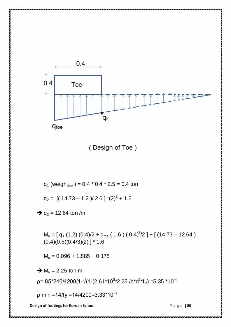
B. Design of Toe :
Design of footings for Korean School P a g e | 80
q1 (weighttoe ) = 0.4 * 0.4 * 2.5 = 0.4 ton
q2 = [( 14.73 – 1.2 )/ 2.6 ] *(2)2 + 1.2
q2 = 12.64 ton /m
Mu = [ q1 (1.2) (0.4)/2 + qtoe ( 1.6 ) ( 0.4)2/2 ] + [ (14.73 – 12.64 )
(0.4)(0.5)(0.4/3)(2) ] * 1.6
Mu = 0.096 + 1.885 + 0.178
Mu = 2.25 ton.m
ρ=.85*240/4200(1-√(1-(2.61*105*2.25 /b*d
2*f
’c) =5.35 *10
-4
ρ min =14/fy =14/4200=3.33*10-3
Design of footings for Korean School P a g e | 81
ρ < ρ min
Use ρ min
As = ρ * b * d
As = 0.0033 * 100 * 33
As = 10.89 cm2/m
:. Use 1 12 / 10 cm
As shrinkage = 0.0018 * 100 * 40
= 7.2 cm2/ m
:. Use 1 12 / 15 cm
Check shear
Vu = (-0.4) (0.4)(1.2) + 12.64 * 0.4 * 1.6 + (14.73 – 12.64 ) *
(0.4) (0.5) (1.6)
Vu = 8.56 ton
But Vc = (0.75) (0.53) ( √240 ) ( 33) ( 100 ) / 1000
Vc = 20.32 ton > 8.56 ton it’s okay

Design of footings for Korean School P a g e | 82
C. Design of Heel :
q1 = 1.6 * 0.4 *2.5 = 1.6 ton/ m2
q1u = 1.6 * 1.2
q1u = 1.92 ton /m2
q2 =1.6* 4* 1.8 = 11.52 ton/m2
q2u = 18.43 ton/m2
q3 = 1.2 q3u = 1.92 ton /m2
Mu = (1.96)(1.6) /2 + 18.43 *1.6 /2 + 1.92 *1.62/2 + ( 15.24 –
1.72 ) *(1.6/2) *(1.6/3)
Mu = 1.53 + 14.74 + 2.45 + 5.68
Mu = 24 .4 ton . m
ρ=.85*240/4200(1-√(1-(2.61*105*24.4 /b*d
2*f
’c) =6.23 *10
-3
ρ min =14/fy =14/4200=3.33*10-3
ρ > ρ min
Use ρ
As = ρ * b * d
As = 0.00623 * 100 * 33
As = 20.55 cm2
:. Use 1 16 / 15 cm

Design of footings for Korean School P a g e | 83
As shrinkage = 0.0018 * 100 * 40
= 7.2 cm2/ m
:. Use 1 12 / 15 cm
Check shear :
Vu = (1.92 +18.43 ) – (1.92 *1.5 ) – (15.24 -1.92) (0.5)(1.6)
Vu = 20.34 – 2.88 – 10.656
Vu = 6.80 ton
But Vc = (0.75) (0.53) ( √240 ) ( 33) ( 100 ) / 1000
Vc = 20.32 ton > 6.80 ton it’s okay

Design of footings for Korean School P a g e | 84
( Reinforcement of the Retaining wall )

Design of footings for Korean School P a g e | 85
CHAPTER FOUR
SUMMERY AND CONCLUSION
This chapter is illustrated the summery and conclusion of the project.
After all investigation and selection of proper foundations. The
following points are stated :
1-The site is located in the north eastern bound of Jenin District
beside Beit Qad street.
2-The area of the site is 18876 m2
3-The soil in the site is mainly clay .
4- The areas around the site are agricultural lands .
5-The school consists of four floors .
6-The total area of the school is 641.6 m2 .
7-The bearing capacity of the soil is 2 kg/cm2 .
8-Combined footings were used in the school .
9-Shear wall and a retaining wall were designed .

Design of footings for Korean School P a g e | 86
CHAPTER FIVE
REFERENCES
1- DasB.” Principles of Geotechnical Engineering”. Adopted
International Student Edition. Thomson Canada Limited. Canada
2007
2- DasB.” Principles of Foundation Engineering”. Adopted
International Student Edition. Thomson Canada Limited. Canada
2007. Sixth Edition .

Design of footings for Korean School P a g e | 87
CHAPTER SIX
APPENDIX
Table 6.1 : Distribution of loads on columns
Column Load (Ton ) C1 55 C2 130 C3 105 C4 105 C5 105
C6 105 C7 105 C8 105 C9 55 C10 55 C11 85 C12 55
C13 130 C14 130 C15 130 C16 130 C17 130 C18 100 C19 55 C20 55
C21 130 C22 60 C23 60 C24 60 C25 A 50 C25 B 50 C26 150 C27 90
C28 90 C29 210 C30 160 C31 90 C32 210 C33 160

Design of footings for Korean School P a g e | 88
C34 90 C35 210 C36 160 C37 50
C38 150 C39 90 C40 55 C41 135 C42 135 C43 60 C44 60
C45 60 C46 60 C47 50 C48 55 C49 130 C50 130 C51 130 C52 130
C53 130 C54 130 C55 100 C56 55 C57 55 C58 85 C59 55
C60 135 C61 135 C62 105 C63 105 C64 105 C65 105 C66 105 C67 105
C68 105 C69 55

Design of footings for Korean School P a g e | 89
Fig 6.1 : Map for footings and columns
Design of footings for Korean School P a g e | 90
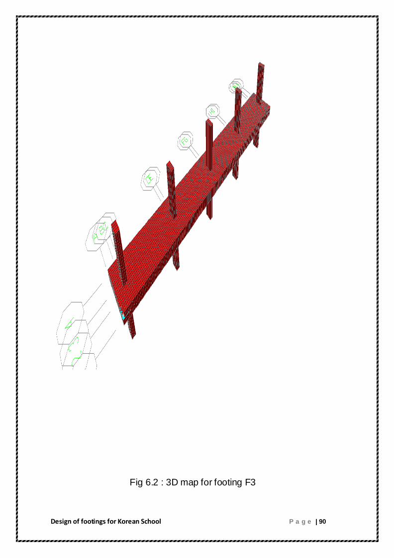
Fig 6.2 : 3D map for footing F3
Design of footings for Korean School P a g e | 91
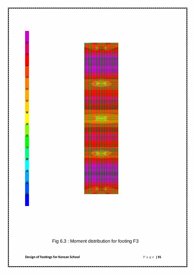
Fig 6.3 : Moment distribution for footing F3