Specalog for 216B/226B/236B Series 3, 242B/252B Series 3 Skid

DEPT. OF INDUSTRY, LABOR & HUMAN RELATIONS 95 Structural
Chapter Ind 53
STRUCTURAL REQUIREMENTS
Ind 53.01 Scope Part I Minimum Allowable Loads Ind 53.10 Dead loads Ind 53.11 Live loads Ind 53.12 Wind loads Ind 53.13 Impact loads Ind 53.14 Load combinations Part II Foundations Ind 53.20 General Ind 53.21 Soil bearing capacity Ind 53.22 Unprepared fill material, organ-
ic material Ind 53.23 Frost penetration Ind 53.24 Piling Ind 53.25 Settlement Ind 53.27 Cut orfill slopes Ind 53.28 Pole foundations Part III Masonry Ind 53.30 General Ind 53.31 Materials Ind 53.311 Masonry units Ind 53.312 Mortar Ind 53.313 Masonry grout Ind 53.314 Cementitious materials Ind 53.315 Water Ind 53.316 Reinforcing, ties and anchors Ind 53.32 Design Ind 53.321 Types of masonry
Ind 53.322 Empirical method of design Ind 53.323 Engineered masonry Ind 53.33 Construction Ind 53.34 Miscellaneous design-construc-
tion details Ind 53.35 Tests Ind 53.36 Veneer, furring and trim Part IV Concrete Ind 53.40 Concrete requi!'ements Ind 53.41 Gypsum concrete requirernents Ind 53.42 Vermiculite concrete require-
ments Part V Metals Ind 53.50 Structural steel requirements Ind 53.51 Cold-formed steel requirements Ind 53.52 Steel joist requirements Ind 53.53 Structural welding of steel Ind 53.54 Aluminum framing require-
ments Ind 53.55 Stainless steel requirements Ind 53.56 Other metals Part VI Wood and Wood Fiber Products Ind 53.60 General Ind 53.61 Materials and design of struc
tural elements Ind 53.62 Special systems Ind 53.63 Minimum construction require
ments
History: Chapter Ind 53 as it existed on December 31, 1974, was repealed and a new chapter Ind 53 was created Register, July, 1974, No. 223, effective January 1, 1975.
Ind 53.01 Scope. This chapter provides the minimum requirements for the structural design of all buildings, structures and foundations to provide safe support of all dead loads, superimposed live and special loads, without exceeding the prescribed allowable stresses or departing from accepted engineering practice.
Note: Wis. Adm. Code chapters Ind 1000-2000, Safety and Health, provides requirements for the safe assembly of materials at the construction site.
Note: References. All standards referred to in this chapter will be identified by the designation and the number of standard followed by a cross-reference. The cross-reference will give full detail of the subject name and year of standard. Example: ASTM C-55 [Ind 51.25 (16) J.
History: Cr. Register, July, 1974, No. 223, eff. 1-1-75.
PART I MINIMUM ALLOWABLE LOADS
Ind 53.10 Dead loads. All buildings and structures, and parts thereOf, shall be designed and constructed to support the actual dead weight of all component members in addition to the weight of partitions, ceiling finishes, floor finishes, stairways, safes and service equipment such as sprinkler systems, plumbing stacks, heating and air conditioning equipment, electrical equipment, elevators, flues and similar fixed equipment which become a part of the building.
Register, December, 1976, No. 252 Building and heating, ventilating
and air conditioning code

96 WISCONSIN ADMINISTRATIVE CODE Structural
Note: Unless the project owner submits a written application for waiver, the department will consider 3 pounds per square foot as minimum service equipment load.
History: Cr. Register, July, 1974, No. 223, eff.1-1-75.
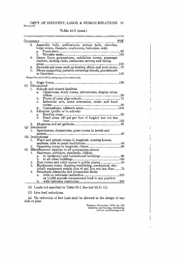
Ind 53.11 Live loads. (1) All buildings and structures, and parts thereof, shall be designed and constructed to support the superimposed live loads, specified in Table 53-I, uniformly distributed in pounds per square foot of horizontal area. These load requirements shall be considered only as a minimum. In every case where the loading is greater than this minimum, the design of the building or structure, or part thereof, shall be for the actual load and loading conditions. The most severe distribution, concentration and combination of design loads and forces shall be taken into consideration.
TABLE 53-1 FLOOR LOADINGS
Occupancy PSF (a) Business
1. Offices ........................................................................................... 50 2. Offices with heavy business machines, heavy files, book
stacks .......................................................................................... 100 (b) Mercantile
1. Retail stores, shops, banks, restaurants, taverns, funeral homes .......................................................................................... 100
2. Wholesale stores ........................................................................ 125 (c) Industrial
1. Manufacturing, light ................................................................. 100 2. Manufacturing, heavy ............................................................... 150
(d) Storage 1. Warehouse, light ........................................................................ 125 2. Warehouse, heavy ...................................................................... 250 3. Paper storage
a. Compact .............................................. 50 psf per ft. of ht. b. Loose ................................................... 30 psf per ft. of ht.
4. Garages-storage or repair ......................................................... 80 or 8,000 pound axle load in any possible position (whichever produces larger stresses) .
5. Parking decks a. All areas for passenger cars ................................................ 50 b. Top floors, if open to sky, shall comply with Ind
53.11 (4) (roof loads) in addition to ................................ 50 c. Express lanes and ramps with a slope of 12 % or
more, the vertical loading (50 psf) shall be increased by 25%
d. All areas for trucks and buses ............................................ 80 or 8,000 pound axle load in any possible position (whichever produces larger stresses)
(e) Assembly areas 1. Armories, drill rooms ................................................................ 150
Register, December, 1976, No. 252 Building and heating, ventilating and air conditioning code
DEPT. OF INDUSTRY, LABOR & HUMAN RELATIONS 97 Structural
Table 53-1 (cont.)
Occupancy PSF 2. Assembly halls, auditoriums, lecture halls, churches,
lodge rooms, theaters, courtrooms, balconies, with: a. Fixed seats ............................................................................ 60 b. Movable seats ..................................................................... 100
3. Dance floors gymnasiums, exhibition rooms, passenger stations, skating rinks, restaurant serving and dining areas ............................................................................................ 100
4. Recreational areas such as bowling alleys and pool rooms .... 75 5. Floors supporting portable reviewing stands, grandstands
or bleachers ................................................................................ 130 Note: See Ind 55.56 for designing of portable units.
6. Stage floors ................................................................................. 150 (f) Educational
1. Schools and related facilities a. Classrooms, study rooms, laboratories, display areas,
offices .................................................................................... 50 b. Floors of open plan schools ................................................ 75 c. Industrial arts, home economics, music and band
rooms ..................................................................................... 80 d. Gymnasiums, cafeteria areas ............................................ 100
2. Libraries (public or in schools) a. Reading areas ....................................................................... 60 b. Stack areas (20 psf per foot of height) but not less
than ..................................................................................... 150 3. Museums and art galleries ......................................................... 80
(g) Residential 1. Apartments, dormitories, guest rooms in hotels and
motels ........................................................................................... .40 (h) Institutional
1. Ward and private rooms in hospitals, nursing homes, asylums, cells in penal institutions .......................................... .40
2. Operating rooms in hospitals, clinics ........................................ 60 (i) Miscellaneous (applies to all occupancies above)
1. Stairways, corridors, vestibules, lobbies a. in residential and institutional buildings ......................... 80 b. in all other buildings ......................................................... 100
2. Rest rooms and toilet rooms in public places .......................... 50 3. Equipment rooms (heating-ventilating, mechanical, elec
trical) equipment weight plus 40 psf, but not less than ........ 75 4. Structural sidewalks and promenade decks
a. with no vehicular restriction ............................................ 250 or 12,000 pounds concentrated load in any position
b. with vehicular restriction .................................................. 100
(2) Loads not specified in Table 53-I. See Ind 53.11 (1).
(3) Live load reductions.
(a) No reduction of live load shall be allowed in the design of any slab or joist.
Register, December, 1976, No. 252 Building and heating, ventilating
and air conditioning code
98 WISCONSIN ADMINISTRATIVE CODE Structural
(b) No reduction of live load shall be allowed in the occupancies mentioned in Table 53-1 subsection (d) storage and (e) assembly areas.
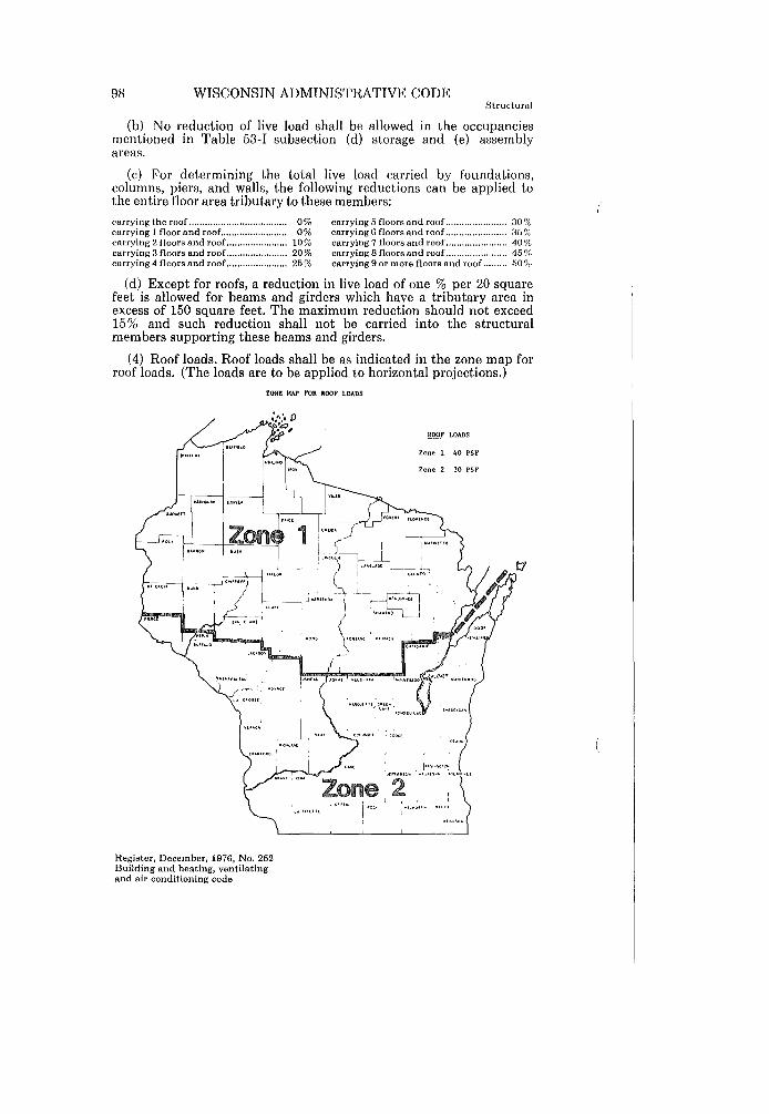
(c) For determining the total live load carried by foundations, columns, piers, and walls, the following reductions can be applied to the entire floor area tributary to these members: carrying the roof ..................................... 0% carrying 5 floors and roof ....................... 30t!i, carrying 1 floor and roof......................... 0% carrying 6 floors and roof ....................... 351};, carrying 2 floors and roof.. ..................... 10% carrying 7 floors and roof ....................... 40% carrying 3 floors and roof. ...................... 20% carrying 8 floors and roof ............ ........ ... 45 % carrying 4 floors and roof ....................... 25% carrying 9 or more floors and roof ......... 50 f}()
(d) Except for roofs, a reduction in live load of one % per 20 square feet is allowed for beams and girders which have a tributary area in excess of 150 square feet. The maximum reduction should not exceed 15% and such reduction shall not be carried into the structural members supporting these beams and girders.
(4) Roof loads. Roof loads shall be as indicated in the zone map for roof loads. (The loads are to be applied to horizontal projections.)
ZONE MAP FOR ROOP LOADS
Register, December, 1976, No. 252 Building and heating, ventilating and air conditioning code

DEPT. OF INDUSTRY, LABOR & HUMAN RELATIONS 99 Structural
(a) Special purpose roofs. Greenhouses shall be designed for not less than one-half the value specified for roof loads.
(b) Increase in roof loads. When there are elevation differences on roof levels, parapets, canopies or valleys which may cause excess snow, ice and/or water accumulation, the designer shall make special provisions for increased loading at such locations.
Note: The department will accept special provisions such as outlined in, but not limited to "Structural Information for Building Design in Canada," Supplement No.3, National Building Code of Canada; or the recommendations of the Metal Building Manufacturers Association.
History: Cr. Register, July, 1974, No. 223, eff. 1-1-75; am. (3) (d) and (4) (a), Register, December, 1974, No. 228, eff. 1-1-75.
Ind 53.12 Wind loads. (1) LOADING. Every building (including all components of the exterior wall) and structure shall be designed to resist a minimum total wind load in accordance with the following table:
Up to 50 feet ........................................................................ 20 psf Over 50 to 100 feet .............................................................. 25 psf Over 100 to 150 feet ............................................................ 30 psf Over 150 to 200 feet.................. .......................................... 35 psf Over 200 feet ............................................................... : ........ 40 psf
The wind pressure shall be taken on the gross area of the vertical projection of the building or structures facing the wind. No allowance shall be made for the shielding effect of other buildings and structures. For purposes of wind load design, the height shall be measured above the average level of the adjoining ground.
(2) UPLIFT AND SUCTION FORCES. Buildings and structures, including attachment of roof to building or structure and anchorage of building or structure to the foundation, shall be designed and constructed to withstand a wind pressure acting outward normal to the surface equal to the values set forth in lnd 53.12 (1). These suction and uplift forces need not be considered as additive to the design wind loads in the overall analysis of the building or structure. Roof overhangs, eaves, cornices, canopies and buildings open on one or more sides shall be designed and constructed to withstand an upward pressure of at least 30 PSF, unless a higher value is indicated in Ind 53.12 (1).
(3) OVERTURNING MOMENT. The overturning moment due to wind load shall not exceed 2/3 of the moment of stability due to dead load only, unless the building or structure is anchored to foundations of sufficient weight to resist this force. The weight of earth superimposed over footings may be used to calculate the dead load resisting moment. Sufficient diaphragm bracing, diagonal bracing or rigid connections between uprights and horizontal members shall be provided to resist distortions.
(4) SHAPE FACTORS. The following shape factors may be used for the design of structures such as chimneys, tanks and solid towers in conjunction with Ind 53.12 (1).
Register, December, 1976, No. 252 Building and heating, ventilating
and air conditioning code

100 WISCONSIN ADMINISTRATIVE CODE Structural
Horizontal cross-section Shape factors
square or rectangular................................................................. 1.0
hexagonal or octagonal.............................................................. 0.8
round or elliptical...................................................................... 0.6
(5) WIND LOAD ANALYSIS. More exact wind load analysis will be acceptable if a recognized procedure is used.
Note: The department will accept recognized procedures sucb as, but not limited to Department of Navy, Bureau of Yards and Docks, NAVFAC DM-2 (Dec. 1967); or "Wind Forces on Structures," by the Structural Division of ASCE Test Committee on Wind Forces (ASCE Transactions, Vol. 126, Part II, Paper No. 3269).
History: Cr. Register, July, 1974, No. 223, eff. 1-1-75; am. (2), Register, December, 1976, No. 252, eff. 1-1-77.
Ind 53.13 Impact loads. (1) LOADING. Structural elements carrying live loads which induce impact shall have the live loads increased by the following minimum percentages in the structural design consideration of such forces:
For supports of elevators ......................................................................... 100 For traveling crane support girders and moving loads .......................... 25 For supports of light machinery ............................................................... 20 For supports of vibrating machinery or power driven units ................. 50 For hangers supporting floors and balconies .......................................... 33
(2) HORIZONTAL AND LONGITUDINAL CRANE FORCES. The lateral force on crane runways shall be equal to 20 % of the sum of the crane capacity and the crane trolley (but exclusive of other parts of the crane). The force shall be assumed to be applied at the top of the rail, one-half on each side of the runway, and shall be considered acting in either direction normal to the runway rail. The longitudinal force (in the direction of rail) shall be taken as 10% of the maximum wheel loads of the crane applied at the top of the rail.
History: Cr. Register, July, 1974, No. 223, eff. 1-1-75.
Ind 53.14 Load combinations. Allowable stresses may be increased 33l!J % when wind loads are acting in combination with dead, live and impact (if any) loads. The section computed on this basis shall be not less than that required for the design dead, live and impact (if any) loads, computed without the 33l!J % stress increase. The most severe distribution, concentration and combination of design loads and forces shall be taken into consideration, as specified in section Ind 53.11.
History: Cr. Register, July, 1974, No. 233, eff. 1-1-75, am. Register, December, 1975, No. 240, eff. 1-1-76.
PART II FOUNDATIONS
Ind 53.20 General. All submittals for plan examination of new buildings or structures, and for the alteration of a permanent structure which requires changes in foundation loads and distribution, shall have the soil types and bearing capacities (indicating verified or presumptive) used in the design of footing and foundations shown on Register, December, 1976, No. 252 Building and heating, ventilating and air conditioning code

DEPT. OF INDUSTRY, LABOR & HUMAN RELATIONS 101 Structural
the plans. Sufficient records and data to establish the soil character, nature and load-bearing capacity shall be available to the department upon request.
History: Cr. Register. July. 1974. No. 223. eff. 1-1-75.
Ind 53.21 Soil bearing capacity. Bearing capacity of soils shall be determined by one of the following methods:
(1) VERIFIED. The soil shall be subjected to field or laboratory tests to determine its bearing capacity. A report, certified by a registered architect or registered professional engineer, shall be available to the department upon request.
(2) PRESUMPTIVE. (a) The type of soil under buildings shall be assigned a value not exceeding the bearing capacity, in pounds per square foot, as specified in Table 53-II. The type of soil shall be determined by explorations made at or adjacent to the site. The actual loading of the soil shall not exceed the specified bearing capacity unless verified by a written report (as explained in subsection (1) above).
TABLE 53-II PRESUMPTIVE SOIL BEARING VALUES
Type of Soil PSF
1. Wet soft clay; very loose silt; silty clay ....................................................... Verified method Ind 53.21 (1)
2. Loose fine sandj medium clay; loose sandy clay soils ................................................... 2,000 3. Stiff clay; firm inorganic silt ............................................................................................. 3.000 4. Medium (firm) sand; loose sandy gravel; firm sandy clay soils; hard dry
clay ....................................................................................................................................... 4.000 5. Dense sand and gravel; very compact mixture of clay. sand and gravel.. .................. 6.000 6. Rock ................................................................................................................................... 12.000
(b) The presumed soil bearing values shall be confirmed by exploring the type of soil to a depth of at least 5 feet below the footings during or before construction. The designer shall submit a report of confirmation to the department upon request.
(c) Where the bearing materials directly under a foundation overlie a stratum having smaller allowable bearing values, such smaller values shall not be exceeded at the level of such stratum.
History: Cr. Register. July. 1974. No. 223. eff. 1-1-75; am. (2) (b). Register. December. 1976. No. 252. eff. 1-1-77.
Ind 53.22 Unprepared fill material, organic material. No foundation of buildings or structures shall be placed upon unprepared fill material, organic soil, alluvial soil or mud unless evidence has been presented to the department showing that the proposed load will be adequately supported. This evidence shall be in the form of a written report and shall be based on soil analyses, load tests or other acceptable criteria.
Note: Tbe decomposition of organic material in landfill sites established for the disposal of organic wastes may produce odorous, toxic and explosive concentrations of gas which may seep into buildings through storm sewers and similar underground utilities unless provisions are taken to release the gases to the atmosphere.
History: Cr. Register. July. 1974. No. 223. eff. 1-1-75.
Register. December. 1976. No. 252 Building and heating. ventilating
and air conditioning code
102 WISCONSIN ADMINISTRATIVE CODE Structural
Ind 53.23 Frost penetration. (1) Footings and foundations shall be placed below the frost penetration level, but in no case less than 42 inches below adjacent ground. Such footings shall not be placed over frozen material.
(2) Exceptions. (a) The edges of floating slabs constructed on grade need not be installed below the minimum frost penetration line provided adequate measures have been taken to prevent frost forces from damaging the structure.
(b) Grade beams need not be installed to the minimum frost penetration line, provided adequate measures are taken to prevent frost forces from damaging the structure.
History: Cr. Register, July, 1974, No. 223, eff. 1-1-75.
Ind 53.24 Piling. (1) GENERAL REQUIREMENT. Pile foundations shall be designed and installed to adequately transfer the structure loads to underlying or adjacent soil bearing strata.
(2) INSTALLATION. Piles shall be handled and installed to the required penetration by methods which leave their strength unimpaired and that develop and retain the required load bearing capacity. Any damaged pile shall be satisfactorily repaired or the pile shall be rejected.
(3) ALLOWABLE LOADS BASED ON SOIL CONDITIONS. (a) By driving formula. For individual pile design loads not exceeding 40 tons per pile, the safe working load may be determined by a recognized formula or by the following formula:
P = 2WH for drop hammer S+l
P = 2E for double-acting hammer S+O.1
in which: P = safe load (lbs.)
W = weight of striking part of hammer (lbs.)
H = fall of striking part of hammer (ft.)
E = manufacturer's rated energy (ft. - Ibs.)
S = average penetration of pile under last 6 blows (inches/blow)
(b) Substantiation of higher allowable loads. Allowable loads greater than 40 tons will be permitted when substantiating data justifying such higher loads is submitted to the department by a foundation designer knowledgeable in the field of soil mechanics and pile foundations and familiar with the locale of the proposed project. Substantiating data such as test borings, laboratory test results, soil profiles, and pile load tests may be required by the department. The load -test shall be in accordance with the procedure outlined in ASTM D-1143 [Ind 51.25 (45) J.
(c) Group pile action. When friction piles are placed in groups, consideration shall be given to the reduction of load per pile. Register, December, 1976, No. 252 Building and beating, ventilating and air conditioning code

DEPT. OF INDUSTRY, LABOR & HUMAN RELATIONS 103 Structural
(d) Piles in subsiding areas. Where piles are driven through subsiding fills or other subsiding strata and derive support from underlying firmer material, consideration shall be given to the downward frictional forces which may be imposed on the piles by the subsiding upper strata.
(e) Lateral support. Water, air and fluid soils shall not be considered as offering lateral support to piles. In any other type of material the piles may be designed as a short column. Positive permanent lateral support shall be provided at or near the top of all piles.
(4) ALLOWABLE LOADS BASED ON PILE MATERIAL STRENGTH. (a) The compressive stress in any cross-section of a pile shall not exceed the normal allowable compressive stress of the material used for the pile, except as given in Ind 53.24 (5). The piles may be designed as short columns except as stated in section Ind 53.24 (B) (e).
(b) End-bearing piles. For end-bearing piles more than 40 feet in length, it may be assumed that 75% of the load is carried by the tip, except for piles installed in a material referred to in section Ind 53.22.
(c) Friction piles. For friction piles, the full load shall be computed at the cross section located at two-thirds of the embedded length of the pile measured up from the tip.
(5) TYPE OF PILES. (a) Timber piles. Timber piles shall conform to National Design Specifications, Part X [Ind 51.27 (8)]. In addition, the tops of treated piles, at cutoff, shall be given 3 coats of hot creosote, followed by a coat of coal-tar pitch; and the cutoff shall be encased not less than 4 inches in concrete footing of the foundation.
(b) Precast concrete piles. Precast concrete piles shall be cast in one piece and shall attain a compressive strength of not less than 3,000 psi prior to driving. There shall be a minimum concrete covering of 2 inches over all reinforcing bars. Precast concrete piles shall be designed to resist stresses induced by handling, driving and superimposed loads.
(c) Cast-in-place concrete pi'tes. All concrete for cast-in-place piles shall develop a compressive strength of not less than 3,000 psi. Reinforcement shall have a concrete cover of one inch in cased piles and 2 inches in uncased piles.
1. Uncased piles. Cast-in-place piles in contact with earth shall be limited in length to 30 times the average diameter of the pile. The allowable compressive stress in concrete shall not exceed 0.33 f'c. The concrete shall be deposited in a shaft free of foreign matter in a continuous operation so as to insure a full sized pile without voids or segregation.
2. Metal formed piles. Cast-in-place piles in contact with a steel shell or casing shall have a minimum tip diameter of 8 inches and a minimum average diameter of 10 inches. The shell and casing shall be sufficiently strong to resist collapse and sufficiently watertight to exclude water and foreign material during the placing of concrete. The shell or casing cannot be considered as a load carrying part of the pile. The allowable compressive stress in concrete shall be as stated for
Register, December, 1976, No. 252 Building and heating, ventilating
and air conditioning code
104 WISCONSIN ADMINISTRATIVE CODE Struct.ural
uncased piles, but it may be increased to a maximum value of 0.40 f'e if the following conditions are satisfied:
a. The thickness of casing is not less than 0.0747 inches (14 ga AISI) .
b. The casing is seamless or is provided with seams of strength equal to that of the casing.
c. The pile diameter is not greater than 18 inches.
(d) Concrete-filled pipe and tapered tubular piles. Concrete-filled pipe and tapered tubular piles may be driven open-ended or closedended. Pipe or tapered tube piles driven with closed ends shall be treated as a cast-in place concrete pile with metal casing and shall be governed by the same regulations applicable thereto with suitable load-bearing allowance made for the metal casing. When driven openended to rock, no concrete shall be deposited until the pipe is cleaned free of all soil or loose rock chips and satisfactory proof furnished of the condition of the rock. The allowable stress in steel is .35 Fy but shall not exceed 12,600 psi. The minimum wall thickness of all loadbearing pipe, tube and shells shall be 1/10 inch. When the soil surrounding the pile contains destructive chemical elements, the pile shall be provided with an approved protective jacket or coating which will not be rendered ineffective by driving.
(e) Structural steel piles. No section shall have a nominal thickness of metal less than 3/8 inch. When an H-shaped section is used, the flange projection shall not be more than 14 times the minimum thickness of metal. The steel stress shall not exceed 0.35 Fy •
History: Cr. Register, July, 1974, No. 223, eff. 1-1-75.
Ind 53.25 Settlement. Where footings or floating slabs are placed upon clays or other materials which are subject to settlement, an analysis for such buildings shall include consideration of total and differential settlements anticipated.
History: Cr. Register, July, 1974, No. 223, eff. 1-1-75.
Ind 53.27 Cut or fill slopes. (1) PERMANENT CUT OR FILL SLOPES. Cuts or fills adjacent to any building, structure or property line shall be so constructed or protected that they do not endanger life and/or property. Permanent cut slopes shall not be steeper than 11-1 horizontal to one vertical and permanent fill slopes shall not be steeper than 2 horizontal to one vertical unless substantiating data justifying steeper slopes are submitted.
. (2) TEMPORARY CUT OR FILL SLOPES. For temporary cuts and fills, refer to Wis. Adm. Codes chapter Ind 6-Trench, Excavation and Tunnel Construction, and chapter Ind 35-Safety in Construction.
History: Cr. Register, July, 1974, No. 223, eff. 1-1-75.
Ind 53.28 Pole foundations. Structures that use poles embedded in earth or embedded in concrete footings in the earth to resist axial and lateral loads shall have their depth of embedment determined as specified in this section. Register, December, 1976, No. 252 Building and heating, ventilating and air conditioning code

DEPT. OF INDUSTRY, LABOR & HUMAN RELATIONS 105 Structural
(1) CONSTRUCTION BACKFILL REQUIREMENTS. The space around the pole shall be backfilled in accordance with one of the following methods:
(a) The hole shall be made 4 inches larger than the diameter or diagonal dimension of rectangular or square poles. It shall be backfilled with 2,000 psi concrete.
(b) The backfill shall be of thoroughly compacted clean sand.
(2) DESIGN-NONRESTRAINED POLES. The following formula shall be used in determining the depth of embedment required to resist lateral loads where no restraint is provided at the ground surface, unless other methods are approved by the department.
d = ~ (1 + J 1+ 4.3~ h )
where: d = depth of embedment, ft. A = 2.34 P
S,B P = applied horizontal force on pole, lb. S, = pd/3, see Table 53-III
Note: For first approximation of Hd", the following formula may be used:
J"i2'hP d=3";=:SP B = diameter of concrete casing, ft.; when nonencased in concrete, diameter or diagonal
dimension of square or rectangular pole, ft. h height above the ground, in feet, at which the force "P" is applied. If the pole has
fixity at the top, such as provided by a knee brace, the force uP" acts at the inflection point. The inflection point may be assumed at ¥, of the distance from the ground to the knee brace for round poles, or V, of the distance from the ground to the knee brace for square poles.
p = allowable lateral passive soil pressure, t psf.
t Unless a more exact soil analysis method is used, the allowable passive soil pressure shall be determined as follows:
TABLE 53-III ALLOWABLE LATERAL SOIL PRESSURE
Soil Types (see Table 53-II)
1 and 2 (not well drained) ................ .. 3 and 4 (well drained) ........................ . 5 and 6 (well drained) ........................ .
Allowable Passive Soil Pressure, psf per foot
of depth below gradett
100 200 400
ttValues may be increased 3S-V, % for wind loads.
S, and S, values shall not exceed, psf
1,500 2,500 6,000
(3) DESIGN-RESTRAINED POLES. Where restraint is provided at the ground surface, such as a rigid floor or pavement, the depth of embedment shall be in accordance with the following formula:
- S,B d -j 4.25 hP
where: S, = pd, see Table 53-III.
(4) MOISTURE. A preservative treatment shall be applied to poles subjected to moisture.
Register, December, 1976, No. 252 Building and heating, ventilating
and air conditioning code
106 WISCONSIN ADMINISTRATIVE CODE Structural
Note: The department will accept poles treated in accordance with the standards of the American Wood Preservers Association for preservative treatments.
History: Cr. Register, July, 1974, No. 223, eiI. 1-1-75; am. (2) and (3), cr. (4), Register, December, 1976, No. 252, eff. 1-1-77.
PART III MASONRY
Ind 53.30 General. (1) SCOPE. The requirements of Ind 53.30 through 53.36 herein shall apply to the design, construction and materials used in all masonry and similar work under this code.
(2) DEFINITION. Masonry as used herein shall be considered as any built-up construction or combination of building units or materials of clay, shale, concrete, stone, gypsum, glass, metal 01' other approved units.
(3) DIMENSIONS. Dimensions specified herein are nominal unless otherwise stated. The actual dimensions may vary from the nominal by the thickness of a mortar joint, but not more than one-half inch.
History: Cr. Register, July, 1974, No. 223, eff. 1-1-75.
Ind 53.31 Materials. (1) GENERAL REQUIREMENTS. Components used in the construction of masonry shall be as required in sections Ind 53.311 through Ind 53.316.
(2) LABELING. All packaged materials shall be clearly identified by name (portland cement, masonry cement, lime, gypsum, etc.) and applicable standards which are met.
History: Cr. Register, July, 1974, No. 223, eff. 1-1-75.
Ind 53.311 Masonry units. (1) GENERAL. (a) Solid and hollow units. A solid masonry unit is a unit whose net cross-sectional area in every plane parallel to the bearing surface is 75% or more of its gross cross-sectional area measured in the same plane. A hollow masonry unit has a net cross-sectional area less than 75 % of its gross crosssectional area.
(b) Quality. All masonry units shall be free from cracks, laminations and other defects or deficiencies, including admixtures and coatings, which may interfere with proper laying of the unit or impair the strength or permanence of the structure.
(c) Used masonry units. Masonry units may be reused when clean, whole and conforming to requirements for new masonry units.
(d) Marking requirements. Masonry units shall be of distinctive design or appearance, or marked so that the manufacturer is identified, as required by the department.
(e) Surface condition at time of use. Every masonry unit shall have all surfaces, to which mortar or grout is to be applied, capable of developing the required strength and bond. Coating or facings permitted and applied to masonry unit surfaces prior to their installation shall not supersede this requirement.
(f) Positioning in structure. Hollow masonry units shall be laid only in positions as tested for compliance. Register, December, 1976, No. 252 Building and heating, ventilating and air conditioning tode

DEPT. OF INDUSTRY, LABOR & HUMAN RELATIONS 107 Structural
(2) CLAY AND SHALE UNITS. Clay and shale units shall be made of burned clay or shale or mixtures thereof with or without admixtures.
(a) Solid units (brick). Units shall conform to grade SW requirements of ASTM C-62 [Ind 51.25 (19)].
(b) Hollow units (tile and hollow brick).
1. Load-bearing units. Units for use in load-bearing and exterior walls shall conform to grade LBX requirements of ASTM C-34 [Ind 51.25 (11)], or grade SW requirements of ASTM C-652 [Ind 51.25 (41) ].
2. Non-load-bearing units. Units for use in non-load-bearing partitions shall be specially marked and shall conform to the requirements of ASTM C-56 [Ind 51.25 (17)]. Such units may also be used for nonstructural purposes in concrete floor construction.
3. Units for floor construction. Units for structural use in floor construction shall conform to grade FT 1 requirements of ASTM C-57 [Ind 51.25 (18)].
(3) CONCRETE UNITS. Concrete units shall be made with portland cement, water and suitable mineral aggregates, with or without admixtures.
(a) Solid units. 1. Small units (brick). Units shall conform to grade N requirements of ASTM C-55 [Ind 51.25 (16)].
2. Large units (solid block). Units shall conform to grade N requirements of ASTM C-145 [Ind 51.25 (30)].
(b ) Hollow units (blocks). Units shall conform to grade N requirements of ASTM C-90 [Ind 51.25 (21)].
(4) NATURAL STONE. All natural building stone for use in masonry shall be sound and free from loose or friable inclusions, and shall meet the strength and fire resistance requirements for the proposed use. Where the cleavage plane of stone units is pronounced, the stone shall be laid only on its natural bed. Stone exposed to soil, weather or frost action shall be such that the strength and structure of the stone will not be affected when so exposed.
(5) CAST STONE. Units covered under this category are homogeneous or faced, dry cast concrete products other than conventional concrete masonry units (brick or block) , but of similar size.
(a) Composition. Units shall be made with portland cement, water and suitable mineral aggregates, with or without admixtures, and reinforced if required.
(b) Standards. Units shall have a minimum compressive strength of 6500 psi and a maximum water absorption of 6 % when tested as 2 x 2 inch cylinders or cubes.
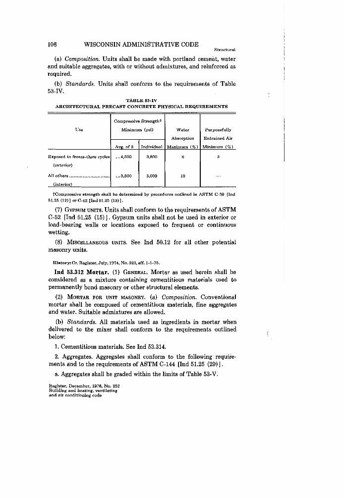
(6) ARCHITECTURAL PRECAST CONCRETE. Units covered under this category are homogeneous or faced, wet cast non-load-bearing concrete products. Load-bearing precast concrete units shall conform to the requirements of Ind 53.40.
Register, December, 1976, No. 252 Building and heating, ventilating
and air conditioning code
108 WISCONSIN ADMINISTRATIVE CODE Structural
(a) Composition. Units shall be made with portland cement, water and suitable aggregates, with or without admixtures, and reinforced as required.
(b) Standards. Units shall conform to the requirements of Table 53-IV.
TABLE 53-IV ARCHITECTURAL PRECAST CONCRETE PHYSICAL REQUIREMENTS
Compressive Strengtht
Use Minimum (psi) Water Purposefully
Absorption Entrained Air
Avg. of 3 Individual Maximum (%) Minimum (%)
Exposed to freeze-thaw cycles .... 4,500 3,800 8 3
(exterior)
All others .................................. .... 3,500 3,000 10 -(interior)
tCompressive strength shall be determined by procedures outlined in ASTM C-39 lInd 51.25 (12) 1 or C-42 lInd 51.25 (13) 1.
(7) GYPSUM UNITS, Units shall conform to the requirements of ASTM C-52 [Ind 51.25 (15)]. Gypsum units shall not be used in exterior or load-bearing walls or locations exposed to frequent or continuous wetting.
(8) MISCELLANEOUS UNITS. See Ind 50.12 for all other potential masonry units.
History: Cr. Register, July, 1974, No.·223, eff. 1-1-75.
Ind 53.312 Mortar. (1) GENERAL. Mortar as used herein shall be considered as a mixture containing cementitious materials used to permanently bond masonry or other structural elements.
(2) MORTAR FOR UNIT MASONRY. (a) Composition. Conventional mortar shall be composed of cementitious materials, fine aggregates and water. Suitable admixtures are allowed.
(b) Standards. All materials used as ingredients in mortar when delivered to the mixer shall conform to the requirements outlined below:
1. Cementitious materials. See Ind 53.314.
2. Aggregates. Aggregates shall conform to the following requirements and to the requirements of ASTM C-144 [Ind 51.25 (29)].
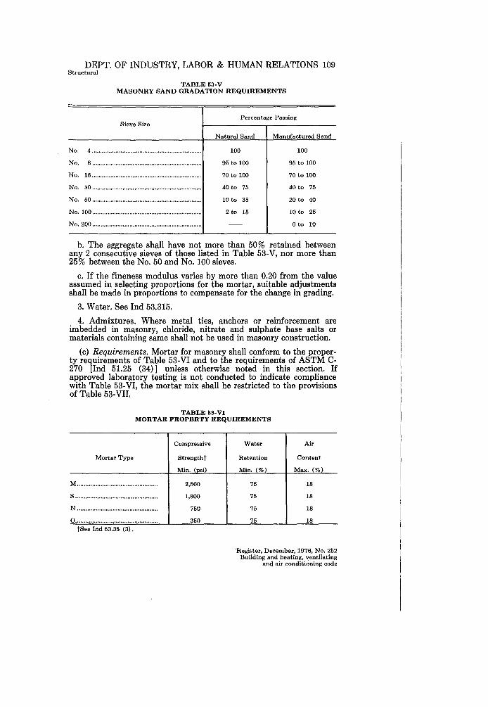
a. Aggregates shall be graded within the limits of Table 53-V.
Register, December, 1976, No. 252 Building and heating, ventilating and air conditioning code
DEPT. OF INDUSTRY, LABOR & HUMAN RELATIONS 109 Structural
TABLE 53-V MASONRY SAND GRADATION REQUIREMENTS
Sieve Size
No.4 ................................................................ .
No.8 ................................................................ .
No. 16 ................................................................ .
No. 30 ............................................................... ..
No. 50 ................................................................ .
No. 100 ................................................................ .
No. 200 ................................................................ .
Percentage Passing
Natural Sand
100
95 to 100
70 to 100
40 to 75
10 to 35
2 to 15
Manufactured Sand
100
95 to 100
70 to 100
40 to 75
20 to 40
10 to 25
o to 10
b. The aggregate shall have not more than 50% retained between any 2 consecutive sieves of those listed in Table 53-V, nor more than 25% between the No. 50 and No. 100 sieves.
c. If the fineness modulus varies by more than 0.20 from the value assumed in selecting proportions for the mortar, suitable adjustments shall be made in proportions to compensate for the change in grading.
3. Water. See Ind 53.315.
4. Admixtures. Where metal ties, anchors or reinforcement are imbedded in masonry, chloride, nitrate and sulphate base salts or materials containing same shall not be used in masonry construction.
(c) Requirements. Mortar for masonry shall conform to the property requirements of Table 53-VI and to the requirements of ASTM C-270 [Ind 51.25 (34) 1 unless otherwise noted in this section. If approved laboratory testing is not conducted to indicate compliance with Table 53-VI, the mortar mix shall be restricted to the provisions of Table 53-VII.
TABLE 53-VI MORTAR PROPERTY REQUIREMENTS
Mortar Type
Compressive
Strengtht
Min. (psi)
M................................................ 2,500
S ................................................. 1,800
N................................................ 750
0................................................. 350 tSee Ind 53.35 (3).
Water Air
Retention Content
Min. (%) Max. (%)
75 18
75 18
75 18
75 18
'Register, December, 1976, No. 252 Building and heating, ventilating
and air conditioning code

110 WISCONSIN ADMINISTRATIVE CODE
TABLE 53-VII MORTAR PROPORTION RESTRICTIONS
Mortar Type
Cementitious Materials (Proportions by Volume)
Portland Masonry Cement Cement Lime
Lime Cement Mortar M ................................................ 1 S ................................................... 1 N .................................................. 1 0 .................................................. 1
Masonry Cement Mortar M ................................................. 1 S .................................................. !h N ................................................. -0 ................................................. -
1 1 1 1
If.! over 1A to Ih over !h to 1 \4 over 1 \4 to 2!h
Structural
Aggregate (Measured in a damp loose
condition)
Not less than 2'1. and not more than 3 times the sum of the separate volumes of cementitious materials.
(3) GYPSUM MORTAR. (a) Standards. Gypsum mortar shall be composed of one part of unfibered calcined neat gypsum to not more than 3 parts sand by weight, with sufficient water added for workability.
(b) Use restrictions. Gypsum mortar shall be used only with gypsum tile and block units or as fireproofing.
(4) MISCELLANEOUS MORTARS. (a) High bond mortars. See section Ind 50.12 for all such mortars, glues and special additives.
(b) Special use mortars. See Table 53-VIII.
(5) BOND. It is required that sufficient bond be developed to hold the masonry assemblage together and let it act as a single unit.
Note: Initial rate of absorption of masonry units and quantity of entrained air in mortar are factors affecting bond strength.
(6) MORTAR USE. Masonry shall be laid in mortar of the types listed in Table 53-VIII.
TABLE 53-VIII MORTAR USE REQUIREMENTS
Kind of Masonr
Load-bearing or non-load bearing masonry in contact with earth All other load-bearing masonry Non-load-bearing masonry in exterior and exposed locations where a high degree of resistance to frost action is desired All other non-load-bearing walls and partitions Fireproofing Special masonry:
Gypsum partition tile or block Firebrick or tile Stack or chimney walls
es of Mortar Permitted
MorS M,SorN
M, SorN
M,S,N orO M, S, N, 0 or gypsum
Gypsum Refractory air setting Composed of portland cement, hydrated lime putty and a re ate
History: Cr. Register, July, 1974, No. 223, eff.1-1-75.
Register, December, 1976, No. 252 Building and heating, ventilating and air conditioning code

DEPT. OF INDUSTRY, LABOR & HUMAN RELATIONS 111 Structural
Ind 53.313 Masonry grout. Masonry grout for non-engineered masonry shall be type M, S or N mortar, as used in the construction, to which water is added to produce a consistency for pouring without segregation.
Note: Masonry grout for reinforced masonry shall conform to the requirements of ASTM C-476 [Ind 51.25 (40) J.
History: Cr. Register, July, 1974, No. 223, eff. 1-1-75.
Ind 53.314 Cementitious materials. (1) PORTLAND CEMENT. Portland cement shall conform to the requirements of ASTM C-150 [Ind 51.25 (31)].
(2) MASONRY CEMENT. Masonry cement shall conform to the requirements of ASTM C-91 [Ind 51.25 (22)].
(3) HYDRATED LIME. Hydrated lime shall conform to Type S requirements of ASTM C-207 [Ind 51.25 (33)].
(4) GYPSUM. Gypsum shall conform to the requirements of ASTM C-22 [Ind 51.25 (9)].
History: Cr. Register, July,1974, No. 233, eff. 1-1-75.
Ind 53.315 Water. Water shall be clean and free from injurious amounts of oil, acid, alkali, salt, organic matter and other deleterious substances.
History: Cr. Register, July, 1974, No. 223, eff. 1-1-75.
Ind 53.316 Reinforcing, ties and anchors. (1) REINFORCING BARS. Reinforcing bars shall conform to the requirements of ASTM A-165 [Ind 51.25 (6)], A-616 [Ind 51.25 (7)], and A-617 [Ind 51.25 (8)].
(2) CONTINUOUS JOINT REINFORCEMENT. (a) Material. Ties shall be fabricated from the equivalent of cold drawn wire conforming to the requirements of ASTM A-82 [Ind 51.25 (3)].
(b) Coating. Ties in exterior walls .and potentially wet areas shall have non corrodible cross wires for the intended use. Conformance with Class 3 requirements of ASTM A-116 [Ind 51.25 (4)] is acceptable.
(c) Assembly. Ties shall consist of the equivalent of at least 2 No.9 steel wire gage longitudinal wires or rods with No. 9 steel wire gage cross wires or rods spaced not over 16 inches apart along each longitudinal wire or rod electrically flush or butt welded to tie the outside wires or rods together and provide mechanical bond.
(d) Limitations. Ties shall be of such dimensions that they provide the following:
1. Overlap of at least 6 inches at splices.
2. Engagement of both adjacent wythes; out-to-out spacing of side rods to be approximately 2 inches less than the total wall thickness.
3. Minimum actual cover over all but the cross wires or rods of 5/8 inch clear from all masonry unit faces and their joint surfaces.
Register, December, 1976, No. 252 Building and heating, ventilating
and air conditioning code
112 WISCONSIN ADMINISTRATIVE CODE Structural
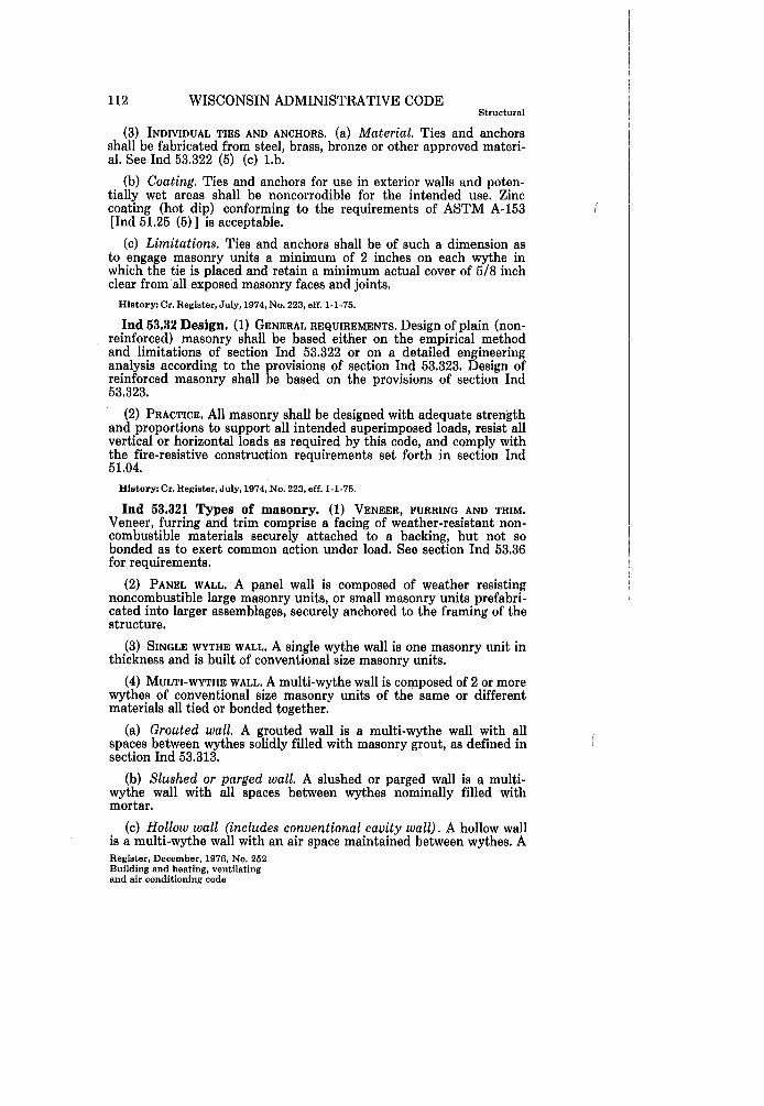
(3) INDIVIDUAL TIES AND ANCHORS. (a) Material. Ties and anchors shall be fabricated from steel, brass, bronze or other approved material. See Ind 53.322 (5) (c) Lb.
(b) Coating. Ties and anchors for use in exterior walls and potentially wet areas shall be noncorrodible for the intended use. Zinc coating (hot dip) conforming to the requirements of ASTM A-153 [Ind 51.25 (5)] is acceptable.
(c) Limitations. Ties and anchors shall be of such a dimension as to engage masonry units a minimum of 2 inches on each wythe in which the tie is placed and retain a minimum actual cover of 5/8 inch clear from all exposed masonry faces and joints.
History: Cr. Register, July, 1974, No. 223, eff. 1-1-75.
Ind 53.32 Design. (1) GENERAL REQUIREMENTS. Design of plain (nonreinforced) masonry shall be based either on the empirical method and limitations of section Ind 53.322 or on a detailed engineering analysis according to the provisions of section Ind 53.323. Design of reinforced masonry shall be based on the provisions of section Ind 53.323.
(2) PRACTICE. All masonry shall be designed with adequate strength and proportions to support all intended superimposed loads, resist all vertical or horizontal loads as required by this code, and comply with the fire-resistive construction requirements set forth in section Ind 51.04.
History: Cr. Register, July, 1974, No. 223, eff. 1-1-75.
Ind 53.321 Types of masonry. (1) VENEER, FURRING AND TRIM. Veneer, furring and trim comprise a facing of weather"resistant noncombustible materials securely attached to a backing, but not so bonded as to exert common action under load. See section Ind 53.36 for requirements.
(2) PANEL WALL. A panel wall is composed of weather resisting noncombustible large masonry units, or small masonry units prefabricated into larger assemblages, securely anchored to the framing of the structure.
(3) SINGLE WYTHE WALL. A single wythe wall is one masonry unit in thickness and is built of conventional size masonry units.
(4) MULTI-WYTHE WALL. A multi-wythe wall is co:tp.posed of 2 or more wythes of conventional size masonry units of the same or different materials all tied or bonded together.
(a) Grouted wall. A grouted wall is a multi-wythe wall with all spaces between wythes solidly filled with masonry grout, as defined in section Ind 53.313.
(b) Slushed or parged wall. A slushed or parged wall is a multiwythe wall with all spaces between wythes nominally filled with mortar.
(c) Hollow wall (includes conventional cavity wall). A hollow wall is a multi-wythe wall with an air space maintained between wythes. A Register, December, 1976, No. 252 Building and heating, ventilating and air conditioning code

DEPT. OF INDUSTRY, LABOR & HUMAN RELATIONS 113 Structural
water-repellent or water-resistant insulation may pe placed between wythes. The description of a hollow wall is determined by its nominal out-to-out dimension.
(5) SPECIAL WALLS (a) Stack or chimney walls. See section Ind 64.46 and Table 53-VIn for general requirements.
(b) Special use walls. See section Ind 53.34 for special requirements.
History: Cr. Register, July,1974, No. 223, eff. 1-1-75.
Ind 53.322 Empirical method of design. (1) STRESSES. (a) General. 1. In determining the stresses in masonry, the effects of all loads and conditions of loading and the influence of all forces affecting the design and strength of the several parts shall be taken into account.
2. When the effects of eccentricity of vertical loads, including loads produced by the deflection of floor and roof units, are likely to cause tensile stresses in the masonry, the masonry shall be designed in accordance with the requirements of section Ind 53.323.
(b) Allowable stresses. 1. Compressive stresses. The compressive stresses in masonry shall not exceed the values given in Table 53-IX.
2. Bearing stresses. See Ind 53.34 (3) (b).
3. Composite masonry. In composite masonry with different kinds or grades of units or mortars, the maximum stress shall not exceed the allowable stress for the weakest combination of units and mortar of which the masonry is composed.
4. Stone flexural members. The maximum allowable flexural stress for natural stone shall be 1/6 of its modulus of rupture.
5. Bolts and anchors. See Ind 53.34 (5).
(2) THICKNESS AND HEIGHT. (a) Height of masonry. The height of a wall is defined for purposes of limitation as the maximum vertical distance between structural members completely supporting the weight of the wall or between the upper such support and the top of the wall. whichever is greater.
(b) Thickness of load-bearing walls. The minimum thickness of load-bearing masonry walls shall be at least 12 inches for the upper 36 feet of their height, and shall be increased 4 inches for the lower 36 feet or fraction thereof. Where a masonry load-bearing wall is made up of 2 or more wythes, the thickness of the wall shall not include any wythe less than 4 inches thick.
Register, December, 1976, No. 252 Building and heating, ventilating
and air conditioning code

$I> o:l!ll ::J" (I) 0.. _.oq ~ s: ai' .... -.~ ... ::J (I) (') (Jq.!1
[§ ~ .... 0.. n
5-;3 a';'~ oq:S.!1 (')~ t--'o < co 0..(1)-> CD:;1$»
E":z ~9 ::J.,
"'''' .,
TABLE c;s..IX
A.LLOWA.BLE COMPRESSIVE STRESSES IN UNIT MASONRYl --
Allowable Compressive Stresses on Gross Cross-Sectional Area3 (psi)
Type of Masonry Type of Masonry Units ------Average Ultimate TypeM Ilofta~ Type N Iltr"ta~ Compressive Strength Mortar Mortar
of Masonry Unit2 (psi) and Grout and Grout and Grout and Grout'
Single wythe and grouted Rubble stone ____________________________ - -- - - - - - - - - - - -- 140 120 100 80 multi-wythe masonry Ashlar granite ____________________________
-- - - - - - - - -- - - -- 800 720 640 500 Ashlar limestone and marble _______________ --------------- 500 450 400 325 Ashlar sandstone and cast stone ____________ - -- - - - - - -- - - - -- 400 360 320 250
Solid units e::~eDt concrete block ___________ 10,000 and over 450 400 350 250 8,000 to 10,000 400 350 300 200 6,000 to 8,000 300 275 250 175 4,000 to 6,000 250 225 200 150 2,500 to 4,000 175 160 140 100
Solid concrete block ______________________ 1,800 and over 175 160 140 100
Hollow load-bearing units _________________ 1,000 and over 90 80 75 60
Slushed or parged multi- All allowable compressive stress values to be 20% less than those for equivalent types of single-wythe and grouted multi-wythe masonry wythe masonry.
Hollow multi-wythe masonry Solid units except concrete block ___________ 2,500 and over 140 130 110 80
Solid concrete block ______________________ I, 800 and over 140 130 110 80
Hollow load-bearing units _________________ 1,000 and over 70 60 55 40 --- --- -- ---- -------
1 Where a type of masonry unit, mortar or grout is not provided for in Table 53-IX, it will be the practice of the department to allow a maximum compressive stress in the masonry which is no more than 15% of the ultimate compressive strength [J)
of a masonry assemblage as determined by an approved test. ~ 2 No individual masonry unit shall have a compressive strength less than 80% of the average ultimate compressive g
st.ength. a-s Stresses shall be calculated on actual dimensions rather than nominal dimensions, with consideration for reductions ~
such as raked joints and cavities. -• Type 0 mortar is permitted only in certain non-load-bearing- masonry. See Table 53-VIII.
......
...... >I>-
::e ...... 00 (") o z 00 ...... Z > t::J ~ ...... Z ...... 00
~ :j -< t>=J (") o t::J t>=J

DEPT. OF INDUSTRY, LABOR & HUMAN RELATIONS 115 Structural
(bm) Exceptions to thickness of load-bearing walls [Ind 53.322 (2) (b)]. 1. Stiffened walls. Where single wythe or grouted multiwythe masonry load -bearing walls composed of units of the same material are laterally supported at distances not greater than 12 feet apart by masonry cross walls or by reinforced concrete floors, they may be of 12-inch thickness for the whole 72 feet.
2. Top-story walls. Top-story walls may be of 8-inch thickness provided that they are not over 12 feet in height and the roof construction imparts no lateral thrust to the walls.
3. One-story walls. In one-story buildings not exceeding 9 feet in height, the walls may be of 6-inch thickness provided that the roof span does not exceed 18 feet.
4. Penthouses and roof structures. Masonry walls above the main roof level, 12 feet or less in height, enclosing stairways, machinery rooms, shafts or penthouses may be of 8-inch thickness, and may be considered as neither increasing the height nor requiring any increase in the thickness of the masonry below.
5. Walls of apartment buildings. In buildings defined as places of abode (Ind 57.001 (2) not including hospitals) not more than 3 stories in height, walls may be of 8-inch thickness when not over 36 feet in height and the roof imparts no horizontal thrust.
6. Walls below grade. Foundation walls shall be not less than 8 inches in thickness nor less than the thickness of the wall which it supports. When subject to lateral pressures, foundation walls shall be limited to a height over thickness (hit) ratio of 9 and shall also have lateral support from vertical elements at a spacing required by Table 53-X.
7. Metal tied hollow walls. Hollow walls shall not exceed 36 feet in height. The space (cavity) between wythes shall be not more than 4 inches. The backing wythe shall be at least as thick as the facing wythe. When both the facing and backing wythes have a thickness of 4 inches, the height of such hollow walls shalf not exceed 24 feet.
8. Masonry bonded hollow walls. Not allowed. Note: For definition of hollow walls, see Ind 53.321 (4) (c).
9. Rubble stone walls. All rubble stone walls shall be 4 inches thicker than required in (b) above, but in no case less than 16 inches in thickness. Other exceptions above do not apply to rubble stone walls.
10. Composite walls. Walls containing clay and concrete masonry units shall not exceed 48 feet in height.
(c) Thickness of exterior non-load-bearing walls and parapets. Non-load-bearing exterior masonry walls may be 4 inches less in thickness than required for load-bearing walls [including the exceptions under. (bm) ], but the thickness shall not be less than 8 inches except where 6-inch walls are specifically permitted.
(cm) Exceptions to thickness of exterior non-load-bearing walls and parapets fInd 53.322 (2) (c)]. 1. Panel walls. Panel walls shall be designed with sufficient strength and thickness and anchored to
Register, December, 1976, No. 252 Building and heating, ventilating
and air conditioning code

116 WISCONSIN ADMINISTRATIVE CODE Structural
the structure so as to insure adequate support and resistance to wind or other lateral forces. Panel walls shall not be less than 2 inches in actual thickness and the maximum ratio of height to thickness shall not exceed 30.
2. Parapet walls. Parapet walls shall not exceed 3 times their thickness in clear height.
(d) Thickness of interior non-load-bearing walls (partitions) . Non-load-bearing interior partitions shall be not less than 4 inches in thickness. Where partitions designed for lateral support at the top are not in tight contact with at least a 2-hour fire-resistive construction at the top, such partitions shall be not more than 24 times their thickness in clear height (see Ind 53.322 (3) (a) 3.).
(3) LATERAL SUPPORT. (a) Requirements. All masonry shall be laterally supported in conformance with the following:
1. Exterior walls. Exterior masonry walls, whether they be loadbearing or non-load-bearing, shall be laterally supported either horizontally or vertically at intervals not exceeding those indicated in Table 53-X.
TABLE 53-X MAXIMUM RATIO OF LATERALLY UNSUPPORTED HEIGHT OR
LENGTH TO THICKNESS FOR ALL EXTERIOR WALLS
Type of Masonry M
Single wythe walls of solid units or grouted walls of solid units ---------------------------------- 22
Slushed or parged walls of solid units-------------- 20
Hollow wallst or walls containing hollow
I
Mortar Type
S
22
20
N
20
18
o
18
16
units ----------------------------------------------------- 18 18 16 12 tIn computing the ratio for hollow walls, the value for thickness shall be the sum of the
nominal thickness of the inner and outer wythes.
2. Load-bearing interior walls. Load-bearing interior walls shall have lateral supports at either vertical or horizontal intervals not exceeding 24 times the wall thickness for solid masonry units and 20 times the wall thickness for hollow masonry units.
3. Non-load-bearing interior walls (partitions). Non-load-bearing partitions shall have lateral supports at either vertical or horizontal intervals not exceeding 30 times the thickness of the wall.
4. Special masonry walls. Exterior masonry walls having no lateral support at the top or at the ends (free standing), shall have their height limited to 4 times their thickness. (See Ind 53.322 (2) (c) 2. for parapet walls.) Similar interior walls (free standing), shall have their height limited to 6 times their thickness.
(b) Methods of lateral support. 1. General. Lateral support shall be provided by cross walls, pilasters or vertical structural members of sufficient strength to provide the required support when the limiting distance is measured horizontally; and/or by floors, roofs or horizontal structural elements which are of sufficient strength to provide the required support when the limiting distance is measured vertically. Register, December, 1976, No. 252 Building and heating, ventilating and air conditioning code

DEPT. OF INDUSTRY, LABOR & HUMAN RELATIONS 117 Structural
Provisions shall be made to transfer all lateral forces to the foundation.
2. Limitations. When horizontal structural elements are depended upon for lateral support, lateral support by vertical elements shall also be provided at intervals of not more than 72 times the wall thickness.
(c) Pilasters. A pilaster is a reinforced or nonreinforced masonry section which is thicker than and integrally bonded or mechanically keyed to the adjoining wall by alternate course bonding of masonry or by the use of pilaster blocks. A mechanically keyed control joint will be permitted on only one side of a pilaster which is used to provide lateral support. The projecting portion of the pilaster. shall be bonded to the wall portion of the pilaster by lapping at least 50 % of the units at the intersection or using special pilaster units.
1. All pilasters relied upon to provide lateral support shall not be less than 4 inches thicker than the wall supported nor less than 1/12 times the pilaster height. The width of pilasters shall be not less than 16 inches.
2. Where a pilaster is needed to carry a concentrated load from a flexural element, the least dimension shall be not less than 1/40 of the span of such an element and the height of the pilaster shall not exceed 12 times the least dimension of the pilaster. All voids, within and between masonry units, shall be fully grouted.
Note: The intent of this rule is to permit the empirical method of design for masonry pilasters carrying concentrated loads provided the pilaster details eliminate the eccentricity and provided the actual stresses are less than or equal to the allowable stresses. Pilasters may also be designed through engineering analysis in accordance with section Ind 53.323.
(d) Piers. A pier is an isolated column of masonry. A load-bearing wall not bonded at the sides into associated masonry shall be considered a pier when its horizontal dimension measured at right angles to the thickness does not exceed 4 times its thickness.
1. All piers shall have lateral supports so that the vertical distance between such supports does not exceed 10 times their least dimension for single wythe or grouted masonry walls of solid masonry units, 8 times their least dimension for slushed or parged masonry walls of solid masonry units, and 6 times their least dimension for other masonry.
2. The least dimension of piers carrying flexural members shall be not less than 1/30 of the span of the flexural members.
3. Piers shall be laid in running bond unless reinforced as required for stack bond walls.
(4) OPENINGS. Unless evidence is provided to show that openings do not cause lateral stability and stress requirements to be exceeded, the amount of openings in a masonry wall shall not exceed the limits set forth in Table 53-XI.
(5) BONDING. (a) General. All types of masonry shall be adequately bonded. .
Register, December, 1976, No. 252 Building and heating, ventilating
and air conditioning code

118 WISCONSIN ADMINISTRATIVE CODE Structural
TABLE 53-XI MAXIMUM RATIO OF LATERALLY UNSUPPORTED HEIGHT OR
LENGTH TO THICKNESS FOR EXTERIOR WALLS WITH OPENINGSt
Type of Masonry Percent of Openings at any Horizontal Plane of Wall
20 40 60 Over 60
Single wythe walls of solid units or grouted walls of solid units ............. 20 16 12 Submit design
calculations All other masonry ................................ 18 14 10
tThe percentage of openings shall be calculated for each 100 lineal feet of wall or portion thereof at any horizontal plane of wall. See Table 53-X for additional restrictions when type uN" or "0" mortar is used.
(b) Longitudinal bond. 1. Running bond. In each wythe of masonry, not less than 60% of the units in any transverse vertical plane shall lap the ends of units above and below a distance not less than 2 inches or 1h the height of the unit, whichever is greater. Masonry not lapped as required above will be considered as stack bond and shall be reinforced longitudinally as required in 2. below for masonry units laid in stack bond.
2. Stack bond. In each wythe of masonry with units laid in stack bond, the masonry shall be reinforced by a continuous tie assembly, as defined in Ind 53.316 (2), at vertical intervals not exceeding 16 inches. For interior non-load-bearing partitions this spacing may be increased to 24 inches. (For load-bearing walls, see also Ind 53.34 (3) (b) 4.)
3. Single wythe exterior concrete masonry walls. Where units are laid in running bond, such masonry wall shall be reinforced by a continuous tie assembly, as defined in Ind 53.316 (2), at vertical intervals not exceeding 24 inches. The requirement for tie assemblies is waived when the spacing of control joints is reduced to 80 % of the values indicated in Table 53-XII, or if the spacing between control joints is 20 feet or less.
(c) Transverse bond. In multi-wythe masonry, adjacent wythes shall be bonded with either metal ties or headers in accordance with the following:
1. Bonding with metal ties. Adjacent wythes of masonry shall be bonded by embedment of reinforcement in the horizontal mortar joints with one of the following methods:
a. Continuous tie assemblies, as defined in Ind 53.316 (2), spaced at vertical intervals not exceeding 16 inches.
b. Individual ties, the equivalent of not less than 3/16 inch diameter steel rods, with one tie for not more than each 4Y2 square feet of wall area. < Ties in alternate courses shall be staggered. The maximum vertical distance shall not exceed 18 inches. The maximum horizontal distance shall not exceed 36 inches. Ties bent to rectangular shape shall be used with hollow masonry units. With solid masonry units, either rectangular ties or ties bent to 90 degree angles, Z shaped, to provide hooks not less than 2 inches long shall be used. In hollow walls, additional ties shall be provided at all openings, spaced not Register, December, 1976, No. 252 Building and heating, ventilating and air conditioning code

DEPT. OF INDUSTRY, LABOR & HUMAN RELATIONS 119 Structural
more than 3 feet apart around the perimeter and within 12 inches of the opening.
2. Bonding with masonry bond units (headers). a. Adjacent wythes of masonry shall be bonded by the equivalent of a full header course overlapping both wythes at least 3 inches and spaced at intervals not greater than every seventh course. The clear distance between bond courses shall not exceed 16 inches for solid units and 24 inches for hollow units. One-seventh of the wall surface shall be header or bond units.
b. In ashlar masonry, bond stones uniformly distributed shall be provided to the extent of not less than 10 % of the area of exposed faces.
c. Rubble stone masonry shall have not less than one bond stone for each 6 square feet of wall surface on both flides. Such walls, 24 inches or less in thickness, shall have bond stones with a maximum spacing of 3 feet vertically and 3 feet horizontally.
d. Hollow walls shall not be bonded with headers. Note: For definition of hollow walls, see Ind 53.321 (4) (c).
3. Interrupted bond. Where a structural member interrupts a backing wythe such that transverse bond otherwise required cannot be achieved, the facing wythe shall be bonded to that structural member as in 1. above.
(d) Bond at intersections and corners. Masonry that changes direction, or meets or intersects other masonry, where dependent for lateral support, shall be bonded by one of the following methods:
1. Walls laid separately. Provide joints with not less than the following:
a. For load-bearing elements, the equivalent of 1\4 inch by \4 inch anchors with ends turned up not less than 2 inches and not less than 24 inches between turned ends, embedded equally into each adjacent wall and spaced not more than 2 feet vertically. Where there is not sufficient thickness of masonry to embed such anchors properly, equivalent anchorage shall be provided by cross-pins or other means.
b. For non-load-bearing elements, the equivalent of 'Vs inch by 22 U.S. gage anchors, 8 inches or more in length, embedded equally into each adjacent wall and spaced not more than 16 inches vertically.
c. When regularly toothed or blocked, the vertical spacing of anchors required above may be doubled.
2. Walls laid simultaneously. Provide joints satisfying one of the following:
a. Lap at least 50 % of the units at the intersection.
b. Use details which are designed to permit differential movement at the intersection of interior and exterior masonry, provided such details are consistent with the requirements for lateral stability of the masonry.
Register, December, 1976, No. 252 Building and beating, ventilating
and air conditioning code
120 WISCONSIN ADMINISTRATIVE CODE Structural
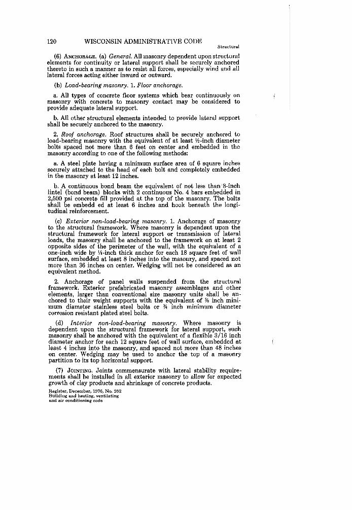
(6) ANCHORAGE. (a) General. All masonry dependent upon structural elements for continuity or lateral support shall be securely anchored thereto in such a manner as to resist all forces, especially wind and all lateral forces acting either inward or outward.
(b) Load-bearing masonry. 1. Floor anchorage.
a. All types of concrete floor systems which bear continuously on masonry with concrete to masonry contact may be considered to provide adequate lateral support.
b. All other structural elements intended to provide lateral support shall be securely anchored to the masonry.
2. Roof anchorage. Roof structures shall be securely anchored to load-bearing masonry with the equivalent of at least Ih-inch diameter bolts spaced not more than 6 feet on center and embedded in the masonry according to one of the following methods:
a. A steel plate having a minimum surface area of 6 square inches securely attached to the head of each bolt and completely embedded in the masonry at least 12 inches.
b. A continuous bond beam the equivalent of not less than8-inch lintel (bond beam) blocks with 2 continuous No.4 bars embedded in 2,500 psi concrete fill provided at the top of the masonry. The bolts shall be embedd ed at least 6 inches and hook beneath the longitudinal reinforcement.
(c) Exterior non-load-bearing masonry. 1. Anchorage of masonry to the structural framework. Where masonry is dependent upon the structural framework for lateral support or transmission of lateral loads, the masonry shall be anchored to the frameWork on at least 2 opposite sides of the perimeter of the wall, with the equivalent of a one-inch wide by lis-inch thick anchor for each 18 square feet of wall surface, embedded at least 8 inches into the masonry, and spaced not more than 36 inches on center. Wedging will not be considered as an equivalent method.
2. Anchorage of panel walls suspended I from the structural framework. Exterior prefabricated masonry assemblages and other elements, larger than conventional size masonry units shall be anchored to their weight supports with the equivalent of Ys inch minimum diameter stainless steel bolts or % inch minimum diameter corrosion resistant plated steel bolts.
(d) Interior non-load-bearing masonry. Where masonry is dependent upon the structural framework for lateral support, such masonry shall be anchored with the equivalent of a flexible 3/16 inch diameter anchor for each 12 square feet of wall surface, embedded at least 4 inches into the masonry, and spaced not more than 48 inches on center. Wedging may be used to anchor the top of a masonry partition to its top horizontal support.
(7) JOINTING. Joints commensurate with lateral stability requirements shall be installed in all exterior masonry to allow for expected growth of clay products and shrinkage of concrete products. Register, December, 1976, No. 252 Building and heating, ventilating and air conditioning code
DEPT. OF INDUSTRY, LABOR & HUMAN RELATIONS 121 Structural
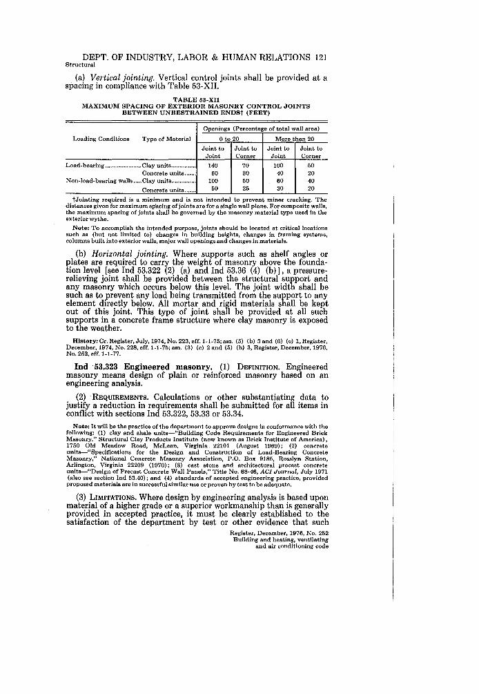
(a) Vertical jointing. Vertical control joints shall be provided at a spacing in compliance with Table 53-XII.
TABLE 53-XII MAXIMUM SPACING OF EXTERIOR MASONRY CONTROL JOINTS
BETWEEN UNRESTRAINED ENDSt (FEET)
Openings (Percentage of total wall area)
Loading Conditions Type of Material o to 20 More than 20
Joint to Joint to Joint to Joint to Joint Corner Joint Corner
Load-bearing ...................... Clay units ............... 140 70 toO 50 Concrete units ....... 60 30 40 20
Non-load-bearing walls ..... Clay units ............... toO 50 60 40
Concrete units ....... 50 25 30 20
tJointing required is a minimum and is not intended to prevent minor cracking. The distances given for maximum spacing of joints are for a single wall plane. For composite walls, the maximum spacing of joints shall be governed by the masonry material type used in the exterior wythe.
Note: To accomplish the intended purpose, joints should be located at critical locations such as (but not limited to) changes in building heights, changes in framing systems, columns built into exterior walls, major wall openings and changes in materials.
(b) Horizontal jointing. Where supports such as shelf angles or plates are required to carry the weight of masonry above the foundation level [see Ind 53.322 (2) (a) and Ind 53.36 (4) (b)], a pressurerelieving joint shall be provided between the structural support and any masonry which occurs below this level. The joint width shall be such as to prevent any load being transmitted from the support to any element directly below. All mortar and rigid materials shall be kept out of this joint. This type of joint shall be provided at all such supports in a concrete frame structure where clay masonry is exposed to the weather.
History: Cr. Register, July, 1974, No. 223, eff. 1-1-75; am. (5) (b) 3 and (6) (c) 1, Register, December, 1974, No. 22S, eff. 1-1-75; am. (3) (c) 2 and (5) (b) 3, Register, December, 1976, No. 252, eff. 1-1-77.
Ind 53.323 Engineered masonry. (1) DEFINITION. Engineered masonry means design of plain or reinforced masonry based on an engineering analysis.
(2) . REQUIREMENTS. Calculations or other substantiating data to justify a reduction in requirements shall be submitted for all items in conflict with sections Ind 53.322, 53.33 or 53.34.
Note: It will be the practice of the department to approve designs in conformance with the following: (1) clay and shale unlts-"Building Code Requirements for Engineered Brick Masonry." Structural Clay Products Institute (now known as Brick Institute of America), 1750 Old Meadow Road, McLean, Virginia 22101 (August 1969); (2) concrete units-"Specifications for the Design and Construction of Load-Bearing Concrete Masonry," National Concrete Masonry Association, P.O. Box 9185, Rosslyn Station, Arlington, Virginia 22209 (1970); (3) cast stone and architectural precast concrete units-"Design of Precast Concrete Wall Panels," Title No. 68-46, ACI Journal, July 1971 (also see section Ind 53.40); and (4) standards of accepted engineering practice, provided proposed materials are in successful similar use or proven by test to be adequate.
(3) LIMITATIONS. Where design by engineering analysis is based upon material of a higher grade or a superior workmanship than is generally provided in accepted practice, it must be clearly established to the satisfaction of the department by test or other evidence that such
Register, December, 1976, No. 252 Building and heating, ventilating
and air conditioning code

122 WISCONSIN ADMINISTRATIVE CODE Structural
quality exists and will only be employed under special inspection or field testing.
History: Cr. Register, July, 1974, No. 223, eff. 1-1-75.
Ind 53.33 Construction. (1) COLD WEATHER WORK. Adequate cold weather construction and protection provisions shall be taken to prevent masonry from being damaged by freezing.
Note: It will be the practice of the department to accept conformance with "Recommended Practices for Cold Weather Masonry Construction," International Masonry Industry All-Weather Council, 1970. (Available from International Masonry Institute, 823 15th StreetNW, Washington, D.C. 20005.)
(2) WORKMANSHIP FOR LOAD-BEARING MASONRY. (a) The maximum thickness of a mortar joint shall be Y2 inch.
(b) Except for head joints used for weep holes and ventilation, solid masonry units shall be laid so as to achieve full head and bed joints.
(c) Hollow masonry units shall be laid with full head joints and full bed joints under the full bearing areas of the face shells (and under webs where the adjacent cells are to be filled with grout) .
(3) CLEANING. Chemical cleaning agents shall be prevented from harming the metal reinforcement of structural components.
History: Cr. Register, July, 1974, No. 223, eff. 1-1-75; r. (1) and renum., Register, December,1974, No. 228, eff.1-1-75.
Ind 53.34 Miscellaneous design-construction details. (1) SPECIAL USE WALLS. (a) Hollow walls. 1. In exterior hollow walls, suitable flashing shall be installed at the bottom of the cavity so as to drain any water outward.
2. Open vertical joints or weep holes of 3fs inch minimum diameter shall be provided in the facing just above the flashing at a horizontal spacing not exceeding 3 feet.
(b) Parapet walls. 1. See Ind 51.01l (12) for requirements of parapet walls.
2. When roof drains are needed to remove precipitation and are the sole means of water escape, there shall be placed in all parapet walls scuppers or relief openings to prevent overloading of the roof ..
(c) Retaining walls. The tops of exposed retaining walls shall be coped with noncombustible weatherproof material.
(d) Reuse of existing walls. Existing masonry may be used in the alteration or extension of a structure, provided that under the new conditions imposed it meets the requirements of this code or is made so by reasonable repairs.
(2) CHANGES IN THICKNESS OR PLANE. (a) Nonvertical planes. Details and techniques for all masonry to be installed in a nonvertical plane shall be submitted to the department for approval.
(b) Thickness change requirements. Where hollow walls or walls of hollow masonry units change in thickness, a course of solid masonry, Register, December, 1976, No. 252 Building and heating, ventilating and air conditioning code
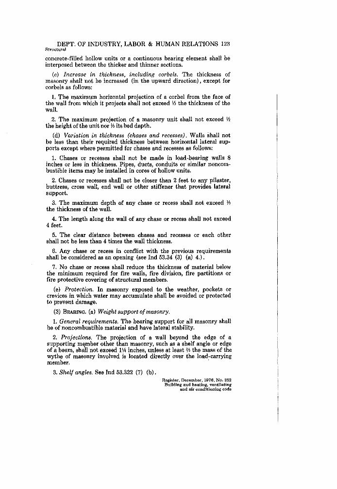
DEPT. OF INDUSTRY, LABOR & HUMAN RELATIONS 123 Structural
concrete-filled hollow units or a continuous bearing element shall be interposed between the thicker and thinner sections.
(c) Increase in thickness, including corbels. The thickness of masonry shall not be increased (in the upward direction), except for corbels as follows:
1. The maximum horizontal projection of a corbel from the face of the wall from which it projects shall not exceed ~ the thickness of the wall.
2. The maximum projection of a masonry unit shall not exceed Y2 the height of the unit nor Ih its bed depth.
(d) Variation in thickness (chases and recesses). Walls shall not be less than their required thickness between horizontal lateral supports except where permitted for chases and recesses as follows:
1. Chases or recesses shall not be made in load-bearing walls 8 inches or less in thickness. Pipes, ducts, conduits or similar noncombustible items may be installed in cores of hollow units.
2. Chases or recesses shall not be closer than 2 feet to any pilaster, buttress, cross wall, end wall or other stiffener that provides lateral support.
3. The maximum depth of any chase or recess shall not exceed ~ the thickness of the wall.
4. The length along the wall of any chase or recess shall not exceed 4 feet.
5. The clear distance between chases and recesses or each other shall not be less than 4 times the wall thickness.
6. Any chase or recess in conflict with the previous requirements shall be considered as an opening (see Ind 53.34 (3) (a) 4.).
7. No chase or recess shall reduce the thickness of material below the minimum required for fire walls, fire division, fire partitions or fire protective covering of structural members.
(e) Protection. In masonry exposed to the weather, pockets or crevices in which water may accumulate shall be avoided or protected to prevent damage.
(3) BEARING. (a) Weight support of masonry.
1. General requirements. The bearing support for all masonry shall be of noncombustible material and have lateral stability.
2. Projections. The projection of a wall beyond the edge of a s'.lpporting mElmber other than masonry, such as a shelf angle or edge of a beam, shall not exceed llA inches, unless at least 2h the mass of the wythe of masonry involved is located directly over the load-carrying member. .
3. Shelf angles. See Ind 53.322 (7) (b). Register, December, 1976, No. 252
Building and heating, ventilating and air conditioning code
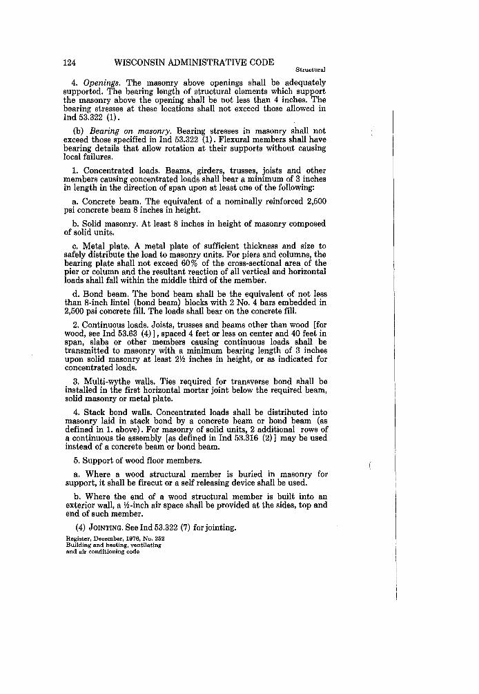
124 WISCONSIN ADMINISTRATIVE CODE Structural
4. Openings. The masonry above openings shall be adequately supported. The bearing length of structural elements which support the masonry above the opening shall be not less than 4 inches. The bearing stresses at these locations shall not exceed those allowed in Ind 53.322 (1).
(b) Bearing on masonry. Bearing stresses in masonry shall not exceed those specified in Ind 53.322 (1). Flexural members shall have bearing details that allow rotation at their supports without causing local failures.
1. Concentrated loads. Beams, girders, trusses, joists and other members causing concentrated loads shall bear a minimum of 3 inches in length in the direction of span upon at least one of the following:
a. Concrete beam. The equivalent of a nominally reinforced 2,500 psi concrete beam 8 inches in height.
b. Solid masonry. At least 8 inches in height of masonry composed of solid units.
c. Metal plate. A metal plate of sufficient thickness and size to safely distribute the load to masonry units. For piers and columns, the bearing plate shall not exceed 60% of the cross-sectional area of the pier or column and the resultant reaction of all vertical and horizontal loads shall fall within the middle third of the member.
d. Bond beam. The bond beam shall be the equivalent of not less than 8-inch lintel (bond beam) blocks with 2 No.4 bars embedded in 2,500 psi concrete fill. The loads shall bear on the concrete fill.
2. Continuous loads. Joists, trusses and beams other than wood [for wood, see Ind 53.63 (4) 1, spaced 4 feet or less on center and 40 feet in span, slabs or other members causing continuous loads shall be transmitted to masonry with a minimum bearing length of 3 inches upon solid masonry at least 2\<2 inches in height, or as indicated for concentrated loads.
3. Multi-wythe walls. Ties required for transverse bond shall be installed in the first horizontal mortar joint below the required beam, solid masonry or metal plate.
4. Stack bond walls. Concentrated loads shall be distributed into masonry laid in stack bond by a concrete beam or bond beam (as defined in 1. above). For masonry of solid units, 2 additional rows of a continuous tie assembly [as defined in Ind 53.316 (2) 1 may be used instead of a concrete beam or bond beam.
5. Support of wood floor members.
a. Where a wood structural member is buried in masonry for support, it shall be firecut or a self releasing device shall be used.
b. Where the end of a wood structural member is built into an exterior wall, a \<2-inch air space shall be provided at the sides, top and end of such member.
(4) JOINTING. See Ind 53.322 (7) for jointing. Register, December, 1976, No. 252 Building and heating, ventilating and air conditioning code
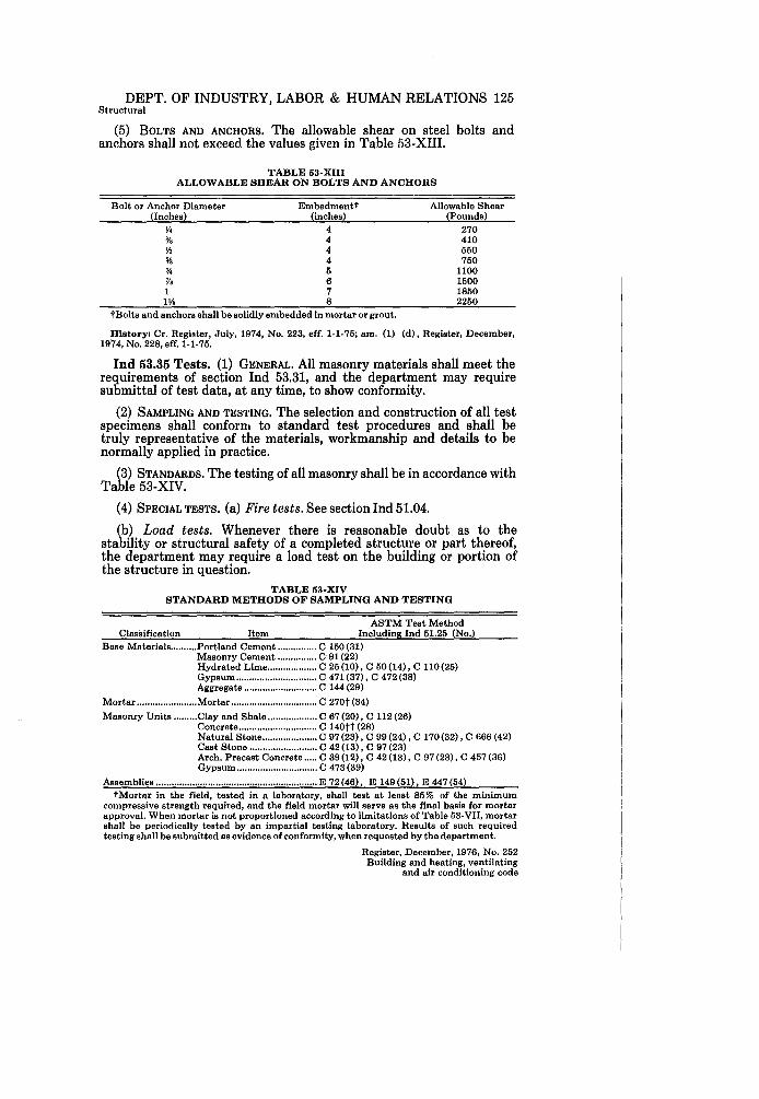
DEPT. OF INDUSTRY, LABOR & HUMAN RELATIONS 125 Structural
(5) BOLTS AND ANCHORS. The allowable shear on steel bolts and anchors shall not exceed the values given in Table 53-XIII.
TABLE 53-XIII ALLOWABLE SHEAR ON BOLTS AND ANCHORS
Bolt or Anchor Diameter Embedmentt (Inches) (inches)
~ 4 ~ 4 ~ 4 ~ 4 ~ 5 % 6 1 7 I'!. S
tBolts and anchors shall be solidly embedded in mortar or grout.
Allowable Shear (Pounds)
270 4lO 550 750
1100 1500 1850 2250
History: Cr. Registar, July, 1974, No. 223, eff. 1-1-75; am. (1) (d), Register, December, 1974, No. 228, eff. 1-1-75.
Ind 53.35 Tests. (1) GENERAL. All masonry materials shall meet the requirements of section Ind 53.31, and the department may require submittal of test data, at any time, to show conformity.
(2) SAMPLING AND TESTING. The selection and construction of all test specimens shall conforn, to standard test procedures and shall be truly representative of the materials, workmanship and details to be normally applied in practice.
(3) STANDARDS. The testing of all masonry shall be in accordance with Table 53-XIV.
(4) SPECIAL TESTS. (a) Fire tests. See section Ind 51.04.
(b) Load tests. Whenever there is reasonable doubt as to the stability or structural safety of a completed structure or part thereof, the department may require a load test on the building or portion of the structure in question,
TABLE 53-XIV STANDARD METHODS OF SAMPLING AND TESTING
ASTM Test Method Classification Item Including Ind 51.25 (No.)
Base Materials .......... Portland Cement ............... C 150 (31) Masonry Cement ............... C 91 (22) Hydrated Lime ................... C 25 (10), C 50 (14), C 110 (25) Gypsum ............................... C 471 (37), C 472 (38) Aggregate ............................ C 144 (29)
Mortar ....................... Mortar ................................. C 270t (34) Masonry Units ......... Clay and Shale ................... C 67 (20), C 112 (26)
Concrete .............................. C 140tt (28) Natural Stone ..................... C 97 (23), C 99 (24) , C 170 (32) , C 666 (42) Cast Stone .......................... C 42 (13), C 97 (23) Arch. Precast Concrete ..... C 39 (12), C 42 (13), C 97 (23), C 457 (36) Gypsum ............................... C 473 (39)
Assemblies .............................................................. E 72 (46), E 149 (51) , E 447 (54) tMortar in the field, tested in a laboratory, shall test at least 85% of the minimum
compressive strength required, and the field mortar will serve as the final basis for mortar approval. When mortar is not proportioned according to limitations of Table 53-VII, mortar shall be periodically tested by an impartial testing laboratory. Results of such required testing shall be submitted as evidence of conformity, when requested by the department.
Register, December, 1976, No. 252 Building and heating, ventilating
and air conditioning code

126 WISCONSIN ADMINISTRATIVE CODE Structural
ttTypical hollow load-bearing concrete masonry unite shall be initially tested for compliance; thereafter periodic testing may be r~qulred as directed by the department. Sampling shall be done only by the department or its authorized agents. The time and place of sampling will be at the discretion of the department.
Note: A record of initial test and subsequent spot checks will be kept by the department.
History: Cr. Register. July. 1974. No. 223. eff. 1-1-75.
Ind 53.36 Veneer, furring and trim. (1) GENERAL. Veneer, furring and trim as used in this section refers to a facing of weather-resistant noncumbustible materials securely attached to a backing, but not so bonded as to exert common action under load.
(a) Veneer shall not be considered as part of the masonry when computing strength or required thickness.
(b) Veneer shall not be assumed as supporting any load other than its own weight.
(2) MATERIAL REQUIREMENTS. (a) General. See section Ind 53.31 for typical requirements of common masonry materials.
(b) Tile and terra-cotta. Such units shall be frost-proof and not more than 288 square inches in area.
(3) THICKNESS. No materials used for veneer shall have a thickness less than the values listed in Table 53-XV.
(4) BEARING AND BACKING SUPPORTS. (a) Bearing and backing supports shall be weather-resistant and shall provide sufficient strength and stability to adequately support the veneer.
TABLE 53-XV MINIMUM THICKNESS OF VENEERS
Material
Clay Brick or Tile .......................................................... .. Concrete Masonry Units ................................................ . Natural Stone .................................................................. . Cast Stone ....................................................................... .. Architectural Precast Concrete .................................... .. Marble Slabs ................................................................... . Slate .................................................................................. . Architectural Terra-cotta .............................................. . Ceramic Veneer-Mechanical Anchorage .................. .. Ceramic Veneer-Adhesion Anchorage ...................... .. Asbestos Cement Boards .............................................. .. Aluminum Clapboard Siding ........................................ . Metal-Corrosion Resistent ......................................... .. Stucco and Exterior Plaster .......................................... .
Minimum Actual thickness (Inches)
1% 1% 1% 1\1.0
% JI. JI.
1 1
3/16 II.
.024 .0149
¥.
(b) Masonry veneer 1% inches or greater in thickness shall be supported by shelf angles or other equivalent weight supports. The spacing between such supports shall not exceed 18 feet vertically when the veneer is more than 30 feet above grade.
(5) ATTACHMENT. (a) General. All veneers, supports and attachments shall be capable of resisting a horizontal force equal to the wind loads specified in section Ind 53.12. Attachment shall be accomplished by mechanical methods or adhesion. Register. December. 1976. No. 252 Building and heating. ventilating and air conditioning code
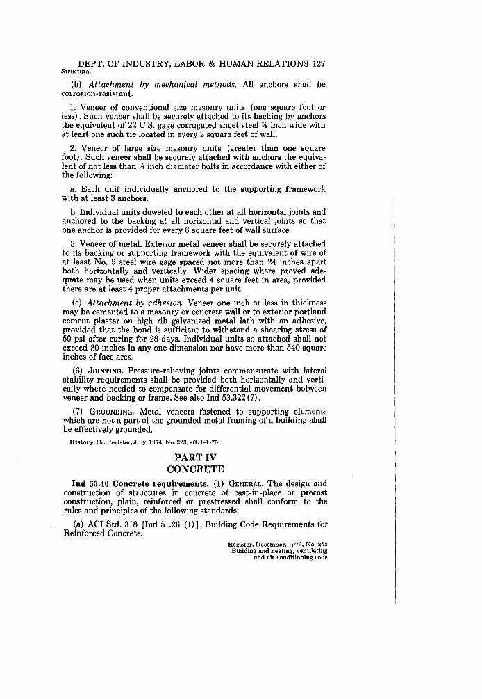
DEPT. OF INDUSTRY, LABOR & HUMAN RELATIONS 127 Structural
(b) Attachment by mechanical methods. All anchors shall be corrosion -resistant.
1. Veneer of conventional size masonry units (one square foot or less) . Such veneer shall be securely attached to its backing by anchors the equivalent of 22 U.S. gage corrugated sheet steel 'VB inch wide with at least one such tie located in every 2 square feet of wall.
2. Veneer of large size masonry units (greater than one square foot). Such veneer shall be securely attached with anchors the equivalent of not less than Y4 inch diameter bolts in accordance with either of the following:
a. Each unit individually anchored to the supporting framework with at least 3 anchors.
b. Individual units doweled to each other at all horizontal joints and anchored to the backing at all horizontal and vertical joints so that one anchor is provided for every 6 square feet of wall surface.
3. Veneer of metal. Exterior metal veneer shall be securely attached to its backing or supporting framework with the equivalent of wire of at least No. 9 steel wire gage spaced not more than 24 inches apart both horizontally and vertically. Wider spacing where proved adequate may be used when units exceed 4 square feet in area, provided there are at least 4 proper attachments per unit.
(c) Attachment by adhesion. Veneer one inch or less in thickness may be cemented to a masonry or concrete wall or to exterior portland cement plaster on high rib galvanized metal lath with an adhesive, provided that the bond is sufficient to withstand a shearing stress of 50 psi after curing for 28 days. Individual units so attached shall not exceed 30 inches in anyone dimension nor have more than 540 square inches of face area.
(6) JOINTING. Pressure-relieving joints commensurate with lateral stability requirements shall be provided both horizontally and vertically where needed to compensate for differential movement between veneer and backing or frame. See also Ind 53.322 (7) .
(7) GROUNDING. Metal veneers fastened to supporting elements which are not a part of the grounded metal framing·of a building shall be effectively grounded.
History: Cr. Register, July, 1974, No. 223, eff.1-1-75.
PART IV CONCRETE
Ind 53.40 Concrete requirements. (1) GENERAL. The design and construction of structures in concrete of cast-in-place or precast construction, plain, reinforced or prestressed shall conform to the rules and principles of the following standards:
(a) ACI Std. 318 [Ind 51.26 (1)], Building Code Requirements for Reinforced Concrete.
Register, December, 1976, No. 252 Building and heating, ventilating
and air conditioning code

128 WISCONSIN ADMINISTRATIVE CODE Structural
(b) ACI Std. 512 [Ind 51.26 (2) 1, Recommended Practice for Manufactured Reinforced Concrete Floor and Roof Units.
(c) ACI Std. 525 [Ind 51.26 (3) 1, Minimum Requirements for Thin Section Precast Concrete Construction.
Note: The following standards and recommendations (1) through (13) are recognized by the department as being good engineering practice: (1) "Commentery on Building Code Requiremente for Reinforced Concrete," ACI Report 31S; (2) "Recommended Practice for Selecting Proportions for Concrete," ACI Std, 211.1; (3) "Recommended Practice for Selecting Proportions for Structural Lightweight Concrete," ACI Std. 211.2; (4) "Recommended Practice for Hot Weather Concreting," ACI Std. 605; (5) "Recommended Practice for Cold Weather Concreting," ACI Std. 306; (6) "Manual of Stendard Practice for Deteiling Reinforced Concrete Structures," ACI Std. 315; (7) "Recommended Practice for Evaluation of Compression Test Results of Field Concrete," ACI Std. 214; (S) "Recommended Practice for Measuring, Mixing and Placing Concrete," ACI Std. 614; (9) "Recommended Practice for Concrete Formwork," ACI Std. 347; (10) "Specification for 'the Design and Construction of Reinforced Concrete Chimneys," ACI Std. 505; (11) "Suggested Design of Joints and Connections in Precast Structural' Concrete," ACI Report 512; (12) "Guide for Cellular Concretes Above 50 pfc, and for Aggregate Concretes Above 50 pfc with Compressive Strengths Less than 2500 psi," ACI JOURNAL, February 1975 (Copies of above standards and recommendations may be obteined from American Concrete Institute, P.O. Box 19150, Redford Station, Detroit, Michigan 4S219); (13) "Recommended Practices for Welding Reinforcing Steel, Metal Inserts and Connections in Reinforced Concrete Construction," AWS Std. 12.1 (American Welding Society, 2501 NW 7th St., Miami, FloridIl33125).
History: Cr. Register, July, 1974, No. 223, eff. 1-1-75.
Ind 53.41 Gypsum concrete requirements. (1) GENERAL. The design and construction of gypsum concrete shall be in accordance with the following standards:
(a) ASTM C 317 [Ind 51.25 (35) 1, Standard Specifications for Gypsum Concrete.
(b) ANSI A 59.1 [Ind 51.27 (5) 1, Specifications for Reinforced Gypsum Concrete.
(2) LIMITATIONS. Gypsum concrete shall not be used where exposed directly to weather or where subject to wetting. Gypsum concrete shall be protected from freezing or coming in contact with moisture during shipment, storage, erection or pouring.
History: Cr. Register, July,1974, No. 223, eff. 1-1-75.
Ind 53.42 Vermiculite concrete requirements. Vermiculite concrete, when used in roof systems and slabs-on-grade, shall be in accordance with: ANSI A 122.1 [Ind 51.27 (5) 1, "Specifications for Vermiculite Concrete Roofs and Slabs-on-Grade." Vermiculite concrete shall not be used where it can be subjected to moisture.
History: Cr. Register, July, 1974, No. 223, eff. 1-1-75.
PART V
METALS
Ind 53.50 Structural steel requirements. The design, fabrication and erection of structural steel for buildings and structures shall conform to: AISC [Ind 51.27 (2) 1 , "Specification for Design, Fabrication and Erection of Structural Steel for Buildings," and the provisions of the accompanying commentary for this specification, with the following modifications: Register, December, 1976, No. 252 Building and heating, ventilating and air conditioning code
DEPT. OF INDUSTRY, LABOR & HUMAN RELATIONS 129 Structural
(1) FABRICATOR SPLICES. Any shop or field connection or splice not specifically shown on the designer's drawings shall have been previously approved by the designer and a record shall be kept of this approval. This record shall be submitted to the department when requested.
(2) LATERAL BRACING MEMBERS. Individual bracing members providing lateral restraint to columns or to compression flanges of beams and girders or to compression chords of trusses shall be proportioned to resist at least 2 percent of the compression force at the brace location unless a suitable analysis is made to determine the appropriate strength and stiffness of the bracing member.
(3) CERTIFICATION AND IDENTIFICATION. (a) Certification. All structural steel shall have a mill report or a test report made in accordance with ASTM A-6 [Ind 51.25 (1)] from the steel supplier; the reports shall include the information on the minimum yield strength and chemistry of the steel furnished. Upon request by the department, the supplier or fabricator shall furnish certified mill reports, test reports, affidavits and/or other information about the steel for the specific project.
(b) Marking of steel. Steel used for main components in completed members or assemblies shall be marked. This marking shall be accomplished by color coding or other means of identification as to its type or gradet prior to shipment from the mill. The marking shall be continued through the fabricator's plant to the construction site. Steel which conforms to ASTM A-36 [Ind 51.25 (2)] designation may be fabricated without marking.
(c) Acceptable steel types. Steel of structural quality shall conform to the standards specified in section 1.4.1.1 of the AISC [Ind 51.27 (2) ]. Steel types not listed in the above mentioned section of the AISC may be used if approved by the designer. An approval letter indicating conformance with Ind 53.50 (3) (a) and (b) shall be sent to the department.
tNote: The type aJ,ld grading may be indicated by the ASTM specification designation or a designation correlated to the information included on the certified mill or test report.
History: Cr. Register,July,1974, No. 223, eff. 1-1-75.
Ind 53.51 Cold formed steel requirements. The design of coldformed steel for buildings and structures shall conform to the AISI [Ind 51.27 (4)] "Specification for the Design of Cold-Formed Steel Structural Members," and the provisions of the accompanying commentary for this specification, with the following modifications:
(1) FABRICATOR SPLICES. See Ind 53.50 (1)
(2) LATERAL BRACING MEMBERS. See Ind 53.50 (2).
(3) CERTIFICATION. See Ind 53.50 (3) (a). History: Cr. Register, July,1974, No. 223, eff. 1-1-75.
Ind 53.52 Steel joist requirements. The design, fabrication and erection of steel joists shall conform to the "Standard Specifications
Register, December, 1976, No. 252 Building and heating, ventilating
arid air conditioning code

130 WISCONSIN ADMINISTRATIVE CODE Structural
for: Open Web Steel Joists, Longspan Steel Joists and Deep Longspan Steel Joists" adopted by the SJI [Ind 51.27 (9)].
History: Cr, Regi.ter, July, 1974, No. 223, eff. 1-1-75.
Ind 53.53 Structural welding of steel. The requirements of this section shall apply to all welds on or between materials within the scope of Ind 53.50, Ind 53.51 and Ind 53.52.
(1) BASE METALS. Steels to be welded under this code are listed in A WS D 1.1, sections 8.2 and 10.2 [Ind 51.27 (6)].
(2) FILLER METALS. Filler metal requirements that are acceptable under this code are listed A WS D 1.1 section 4.1 [Ind 51.27 (6)].
(3) WELDING PROCESSES. (a) Manual shielded metal arc, submerged arc, gas metal arc and flux cored arc welding processes conforming with the procedures established in AWS D 1.1, sections 2, 3 or 4 [Ind 51.27 (6)] shall be considered as pre qualified and are approved for use without performing procedure qualification tests.
(b) Electroslag and electrogas welding processes will not be considered as prequalified. They may be used provided a procedure is developed and provided it conforms to the applicable provisions of A WS D 1.1, sections 2, 3 or 4 [Ind 51.27 (6)].
(4) WELDING PROCEDURES. (a) Procedure specification. All welding procedures shall be prepared as a written procedure specification. This written procedure specification shall be prepared by the manufacturer, fabricator or contractor and shall be made available or submitted to the department when requested.
Note: Suggested form SB-223A, showing the information required in the procedure specification, may be obtained from the department.
(b) Procedure qualification. All joint welding procedures shall be previously qualified by tests as prescribed in AWS D 1.1 section 5.6 [Ind 51.27 (6)], except for the prequalified procedures exempted in Ind 53.53 (3) (a). The test shall be conducted under the supervision of an approved testing laboratory and the test results shall be submitted to the department for approval.
(5) DESIGN OF WELDED CONNECTIONS AND JOINTS. The details of all joints shall comply with the requirements of A WS D 1.1, section 2 and section 10, parts III and IV [Ind 51.27 (6)]. A joint form not specified in A WS D 1.1, section 2 and section 10, parts III and IV, shall not be used until it is qualified to the satisfaction of the department.
(a) Stud welding. Stud welding shall be done by a procedure qualified in accordance with the requirements of A WS D 1.1, section 4, part VI [Ind 51.27 (6»).
(6) OPERATOR QUALIFICATIONS. All struct.ural welding work shall be done by certified [as defined in Ind 53.53 (7)] welders. The required qualification test shall be conducted under the supervision of an approved testing laboratory, The weld test report shall 'be submitted to the department for evaluation. Test specimens shall be submitted when requested by the department. Register, December, 1976, No. 252 Building and heating, ventilating and air conditioning code
DEPT. OF INDUSTRY, LABOR & HUMAN RELATIONS 131 Structural
(a) The manual welders shall be tested and qualified in accordance with A WS D 1.1, section 5, part III [Ind 51.27 (6)]
(b) The manual tackers shall be tested and qualified in accordance with A WS D 1.1 section 5, part V [Ind 51.27 (6)]
(c) The welding machine operator shall be tested and qualified in accordance with A WS D 1.1, section 5, part IV [Ind 51.27 (6)].
(7) OPERATOR CERTIFICATION. The department will issue to the welder or welding machine operator who has successfully passed the prescribed qualification tests, a certificate bearing his name, social security number, identifying mark, the process, the procedure specification number and other pertinent information from his qualification test. This certificate will remain in effect for 3 years provided the operator is continuously engaged in welding operations without an interruption of more than 3 consecutive months. If the interruption exceeds 3 consecutive months, the certificate shall automatically become void.
(a) Each manual welder and tacker or welding machine operator shall be retested every 3 years in accordance with Ind 53.53 (6).
(b) Each manual welder and tacker or welding machine operator certificate which has become void due to welding operation interruption exceeding 3 consecutive months or having exceeded the 3-year certificate time limit can be renewed only be retesting at an approved testing laboratory.
(8) WELD IDENTIFICATION. Each structurally significant member shall have its welding identified by a distinguishing mark stamped on the member by the certified welders involved.
(9) CRITERION OF FINAL ACCEPTANCE. All structural welding is subject to examination by approved inspectors and such inspection shall be the final criterion for conformance and acceptability for the intended use.
(10) STRUCTURAL WELDING DONE OUTSIDE THE STATE OF WISCONSIN. All welding shall conform with the requirements of section Ind 53.53. In addition, manufacturers and suppliers of structural steel. shall, prior to commencing any welded construction, submit evidence of procedure qualification and welder certification that has been approved by an independent testing laboratory which is acceptable to the department.
History: Cr. Register, July, 1974, No. 223, eff. 1-1-75.
Ind 53.54 Aluminum framing requirements. The design, fabrication and erection of aluminum structural framing members shall conform to "Specifications for Aluminum Structures" [Ind 51.27 (1) ] , published by The Aluminum Association.
History: Cr. Register, July,1974, No. 223, eff. 1-1-75.
Ind 53.55 Stainless steel requirements. The design, fabrication and erection of light gage stainless steel framing members shall
Register, December, 1976, No. 252 Building and heating, ventilating
and air conditioning code
132 WISCONSIN ADMINISTRATIVE CODE Structural
conform to AISI [Ind 51.27 (4) 1, "Specification for the Design of Light Gage, Cold-Formed Stainless Steel Structural Members."
History: Cr. Register, July, 1974, No. 223, eff. 1-1-75.
Ind 53.56 Other metals. The design, fabrication and erection of other metals or metal alloys not specifically listed in this section shall be in accordance with the provisions of section Ind 50.18.
History: Cr. Register, July, 1974, No. 223, eff. 1-1-75; am. Register, December, 1976, No. 252, eff. 1-1-77.
PART VI
WOOD AND WOOD FIBER PRODUCTS Ind 53.60 General. (1) SCOPE. The requirements of sections Ind
53.60 to 53.63, inclusive, shall apply to' the materials, design, and construction procedures used in all wood and wood fiber products construction work under this code.
(2) DEFINITION. Wood and wood fiber products include those structural elements derived from solid wood, structural glued-laminated timber, plywood, fiberboard, hardboard and other wood-fiber-based materials.
History: Cr. Register, July 1974, No. 223, eff. 1-1-75.
Ind 53.61 Materials and design of structural elements. (1) SAWN LUMBER. The material characteristics and the design provisions ofloadbearing structural sawn lumber shall be in accordance with the following adopted standard and listed exceptions:
(a) "National Design Specifications for Stress-Grade Lumber and Its Fastenings" [Ind 51.27 (8) 1 and its Supplement Table 1, including Tables la and lb.
1. Exceptions:
a. Section 200-B-1. The provisions of this section shall also apply to reused lumber. Reused lumber shall be considered to have a duration of load factor of 0.90.
b. Section 200-G-1. In addition to requiring grading in conformance with ASTM D 245 [Ind 51.25 (43) 1, lumber (including reused lumber) of species and grades not listed in Table 1 of the supplement to the NDS [Ind 51.27 (8) 1 shall be identified by the grade mark of, or certificate of inspection issued by, a lumber grading or inspection bureau or agency recognized as being competent.
c. Section 203-A. The cumulative effects of short-time loads, such as snow, shall be considered in determining duration of load. For snow load, no greater duration of load factor than 1.05 shall be used.
d. Section 102-D. Refer to section Ind 53.11. The combination of full snow load with wind load shall be taken into consideration.
e. Part IX is deleted. Refer to section Ind 53.61 (2). Register, December, 1976, No. 252 Building and heating, ventilating and air conditioning code

DEPT. OF INDUSTRY, LABOR & HUMAN RELATIONS 133 Structural
(2) STRUCTURAL GLUED-LAMINATED TIMBER. Structural glued-laminated timber is an engineered, stress-rated product ofa timber laminating plant comprising assemblies of specially selected and prepared wood laminations securely bonded together with adhesives. The grain of all laminations is approximately parallel longitudinally. The following standards are adopted as part of this building code for the design and production of structural glued-laminated timber, except that the modification of design stresses for duration of load shall be as specified in Ind 53.61 (1) (a) 1.c.
(a) AITC 117 [Ind 51.27 (3)], "Standard Specifications for Structural Glued-Laminated Timber of Douglas Fir, Western Larch, Southern Pine and California Redwood."
(b) AITC 119 [Ind 51.27 (3)], "Sta.ndard Specifications for Hardwood Glued-Laminated Timber."
(c) AITC 120 [Ind 51.27 (3)], "Standard Specifications for Structural Glued-Laminated Timber Using 'E' Rated and Visually Graded Lumber of Douglas Fir, Southern Pine, Hem Fir and Lodgepole Pine."
(3) ROUND POLES. Allowable unit stresses for nongraded round poles used as structural members other than piling shall be 80 percent of the allowable unit stresses for select structural grade beams and stringers (19 percent moisture content) of the appropriate species as listed in Table 1, supplement to the National Design Specification for Stress Grade Lumber and Its Fastenings [Ind 51.27 (8)]. No obviously unsound load-bearing poles are to be used. Higher allowable stresses will be permitted for round poles graded in accordance with a recognized standard.
Note: ASTM designation D 3200-73 "Standard Specification and Methods for Establishing Recommended Design Stresses for Round Timber Construction Poles" is acceptable for graded round poles. ANSI Standard 05.1-1972 may be used for poles subject to transverse loads only.
(4) PILING. See section Ind 53.24.
(5) PLYWOOD. (a) General. The quality and design of all plywood used in construction of all buildings and structures shall conform to the minimum standards under this section. All plywood when used structurally, including among others, use for siding, roof and wall sheathing, subflooring, diaphragms, and built-up members, shall conform to the performance standards for its type in U.S. Product Standard PS 1 [Ind 51.27 (11)] for softwood plywood/construction and industrial. Each panel or member shall be identified for grade and glue type by the trademarks of an approved testing and grading agency. In addition, all plywood when permanently exposed in outdoor applications shall be of exterior type.
Note: It will be the policy of the department to approve designs in conformance with the following: (1) "Plywood Design Specification" including Supplement No. 1 "Design of Plywood Curved Panels"; Supplement No.2 "Design of Plywood Beams"; Supplement No.3, "Design of Flat Plywood Stressed-Skin Panels"; and Supplement No. 4 "Design of Flat Plywood Sandwich Panels"; (2) "Plywood Diaphragm Construction"; (3) Laboratory Report 121, "Plywood Folded Plate Design and Details"; (4) Laboratory Report 93, "LoadBearing Plywood Sandwich Panels"; and (5) "Fabrication Specifications Plywood-Lumber Components: CP-8, BB-8, SS-8, SP-61, FF-62, PW-61" (above pUblications available from the American Plywood Association, 1119 A Street, Tacoma, Washington 98401); (6) Design
Register, December, 1976, No. 252 Building and heating, ventilating
and air conditioning code

134 WISCONSIN ADMINISTRATIVE CODE Structural
Guide HP-SG-71, "Structural Design Guide for Hardwood Plywood" (available from the Hardwood Plywood Manufacturers Association, 2310 South Walter Reed Drive, Arlington, Virginia 22206).
Note 2: The department will accept plywood treated in accordance with the standards of the American Wood Preservers Association.
(b) No part of any of the . above referenced standards shall supersede the general live load requirements of section Ind 53.11.
(6) RECONSTITUTED WOOD BASE-FIBER AND PARTICLE PANEL MATERIALS. Materials of this type, when used structurally, shall be approved by the department in accordance with the requirements of section Ind 50.12. Evaluation will be based on ASTM D 1037 [Ind 51.25 (44)].
(7) SOLID WOOD FLOOR AND ROOF SHEATHING. Minimum thickness of nonstress rated lumber used for floor and roof sheathing shall be in accordance with Table 53-XVI.
TABLE 53-XVI MINIMUM NET THICKNESS OF LUMBER PLACED (INCHES)
Per~endicular to Su~~ort Diagonal to Su~~ort
Use Span Surfaced Surfaced Surfaced Surfaced (Inches) Dr;tt Unseasoned Dr;tt Unseasoned
Floors ............... 24 3/4 25/32 3/4 25/32 16 5/8 11/16 5/8 11/16
Roofs ................ 24 5/8 11/16 3/4 25/32
tMaximum 19% moisture content.
(a) The above dimensions shall be the mInimum dimensions for lumber with grades as specified in Table 53-XVII.
TABLE 53-XVII MINIMUM BOARD GRADESt
Grading Agenc;t Solid Floor or Roof
Sheathing Spaced Roof Sheathing
West Coast Lumber Inspection Bureau .................... Utility Standard Western Wood Producta Association ............. 4 Common or Utility 3 Common or Standard Southern Pine Inspection Bureau ............................... No.3 No.2 Redwood Inepection Service ................................. Merchantable Construction, common National Lumber Grades Authority ............... 4 Common or Utility 3 Common or Standard Northern Hardwood and Pine
Manufacturers AS8ociation ................................... 4 Common 3 Common Northeastern Lumber Manufacturers
Association .............................................................. 4 Common 3 Common
tThe above grades are taken from grading rules approved by the American Lumber Standards Committee.
(8) TIMBER FASTENERS. The design and use of timber fasteners shall be in accordance with the requirements of National Design Specifications for Stress-Grade Lumber and Its Fastenings [Ind 51.27 (8)].
(a) Fastener identification. Light gauge perforated metal plate connectors shall be permanently identifiable with regard to their gauge and manufacturer.
History: Cr. Register, July, 1974, No. 223, eff. 1-1-75; am. (2) Register, December, 1974, No. 228, eff. 1-1-75; r. and recr. (2), Register, April, 1975, No. 232, eff. 5-1-75.
Register, December, 1976, No. 252 Building and heating, ventilating and air conditioning code
DEPT. OF INDUSTRY, LABOR & HUMAN RELATIONS 135 Structural
Ind 53.62 Special systems. (1) WOOD TRUSSES. Wood trusses shall be constructed in accordance with the following recommended standard and the listed exceptions:
(a) "Design Specifications for Light Metal Plate Connected Trusses" [Ind 51.27 (10)].
1. Exceptions and additions:
a. Section 301.2. Moment coefficients used in design of top or bottom chord members shall be based on the assumption of no fixity at member ends or joints due to plate connectors.
b. Metal plate connectors shall be identifiable as stated in Ind 53.61 (8) (a).
c. The modification of design stresses for duration of load shall be as specified in Ind 53.61 (1) (a) 1.c.
(b) For trusses with nail-glued plywood gusset plates, calculations and design reference source shall be submitted to the department.
(c) Mechanically fastened trusses shall conform to Part V, "Timber Connector Joints," of National Design Specifications [Ind 51.27 (8)].
History: Cr. Register, July, 1974, No. 223, eff. 1-1-75; cr. (1) (a) I.c., Register, December, 1974, No. 228, eff. 1-1-75.
Ind 53.63 Minimum construction requirements. The requirements of this section shall apply to all wood framing.
Note: Recognized wood framing and construction details indicated in "Wood Construction Data No.1 and No.5" of the National Forest Products Association, Technical Services Division (1619 Massachusetts Ave. NW, Washington, D.C. 20036) is recommended as good design and construction practice.
(1) FIRE STOPS. Fire stops shall be provided at all intersections of interior and exterior walls with floors, ceilings and roof in such manner as to effectively cut off communication by fire through hollow concealed spaces and prevent both vertical and horizontal drafts.
(a) Furred walls shall have fire stops placed immediately above and below the junction of any floor construction with the walls, or shall be fire-stopped the full depth of the joist.
(b) All spaces between chimney and wood framing shall be solidly filled with noncombustible material at floor levels.
(c) All wood fire stops as required in this section shall be lumber not less than 2 inches in nominal thickness, or 3/4-inch thick plywood with joints backed, and not less in width than the enclosed space within the partition except as provided for chimneys. Fire stops may also be of gypsum board, cement asbestos board, mineral wool or other approved noncombustible materials, securely fastened in place.
(2) WOOD FRAMING INTO FIRE-RATED MASONRY WALLS. See Ind 51.045 (1) (m).
(3) FIRE-CUTTING. Wood members supported in masonry walls shall have the ends of such members splayed or firecut to allow free end
Register, December, 1976, No. 252 Building and heating, ventilating
and air conditioning code

136 WISCONSIN ADMINISTRATIVE CODE Structural
rotation in the vertical plane of the member, out of the masonry wall. See also Ind 53.34 (3) (b) 5.b.
(4) BEARING. (a) Joists and trusses. The ends of each joist or truss shall have not less than 1 V2-inch length of bearing on wood or metal nor less than 3-inch length on hollow or solid masonry units.
(b) Beams and girders. The ends of beams or girders supported on masonry or concrete shall have not less than 4-inch length of bearing. See also Ind 53.34 (3).
(5) NOTCHING AND DRILLING. No notching of outer fibers of structural members is permitted unless substantiated by design calculations. Circular holes bored in joists and studs that are within the middle one-third of the depth of joist or studs are permitted without design calculations.
(6) DECAY PREVENTION. Where wood is used in parts of a building exposed to moisture that causes the moisture content of wood to exceed 19 %, the wood shall be adequately ventilated or treated with preservative.
Note: The department will accept wood producte treated in accordance with the standards of the American Wood Preservers Association and the American Wood Preservers Bureau.
(a) All wood columns, posts and frame legs whose base is subject to deterioration due to moisture shall bear on concrete or other inorganic materials which extend at least 3 inches above the adjacent surface unless treated with preservative.
(b) The ends of wood structural members built into exterior masonry walls or into concrete shall be treated with preservative or a moisture-proof barrier shall be installed on the bearing surface.
Note: In areas subject to termita attack, refer to "Design of Wood Structures for Permanence" (published by the National Forest Producte Association, 1619 Massachusette Ave. NW, Washington, D. C. 20036) as suggested by National Design Specifications [Ind 51.27 (8) 1, Appendix F, section B.2.
(7) TRUSS BRACING AND ANCHORAGE. All wood trusses shall be securely fastened to the supports and each truss shall be secured in position in accordance with National Design Specifications [Ind 51.27 (8) ] , Appendix F, section J.
(8) ANCHORAGE. Anchorage shall be in accordance with subsection Ind 53.12 (2).
(9) CROSS BRIDGING. Cross bridging shall be furnished in accordance with paragraph 300-J of NDS [Ind 51.27 (8)]. When joists support floor or roof decks other than wood or wood decks which are not adequately attached, cross bridging shall be provided at 8-foot intervals.
(10) SOLID BLOCKING. All floor and roof joists shall be supported laterally at the ends and at each support by solid blocking except when the ends of joists are nailed to a header, band or rim joist or to an adjoining stud. Solid blocking shall be provided between floor joints where subjected to concentrated loads. Solid blocking shall be Register, December, 1976, No. 252 Building and heating, ventilating and air conditioning code
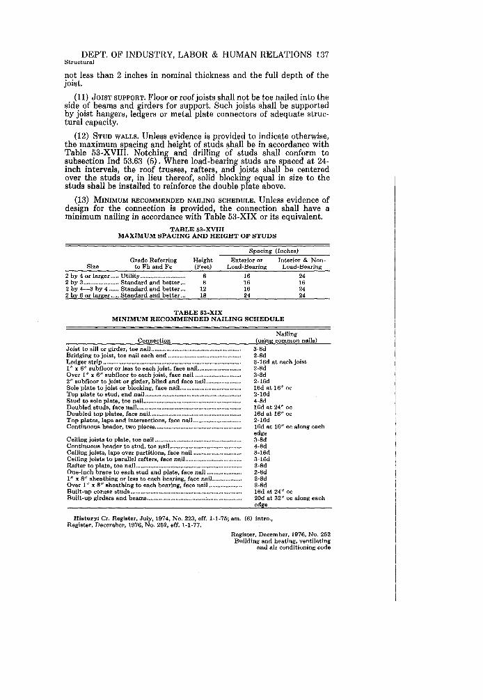
DEPT. OF INDUSTRY, LABOR & HUMAN RELATIONS 137 Structural
not less than 2 inches in nominal thickness and the full depth of the joist.
(11) JOIST SUPPORT. Floor or roof joists shall not be toe nailed into the side of beams and girders for support. Such joists shall be supported by joist hangers, ledgers or metal plate connectors of adequate structural capacity.
(12) STUD WALLS. Unless evidence is provided to indicate otherwise, the maximum spacing and height of studs shall be in accordance with Table 53-XVIII. Notching and drilling of studs shall conform to subsection Ind 53.63 (5). Where load-bearing studs are spaced at 24-inch intervals, the roof trusses, rafters, and joists shall be centered over the studs or, in lieu thereof, solid blocking equal in size to the studs shall be installed to reinforce the double plate above.
(13) MINIMUM RECOMMENDED NAILING SCHEDULE. Unless evidence of design for the connection is provided, the connection shall have a minimum nailing in accordance with Table 53-XIX or its equivalent.
TABLE 53-XVIII MAXIMUM SPACING AND HEIGHT OF STUDS
Spacing (Inches)
Grade Referring to Fb and Fe
Height (Feet)
Exterior or Interior & Non-Size Load-Bearing Load-Bearing
2 by 4 or larger ..... Utility .......................... . 2 by 3 ..................... Standard and better .. . 2 by 4-3 by 4 ...... Standard and better .. . 2 by 6 or larger ..... Standard and better .. .
8 8
12 18
TABLE 53-XIX
16 16 16 24
24 16 24 24
MINIMUM RECOMMENDED NAILING SCHEDULE
Connection Joist to sill Or girder, toe nail ..................................................... . Bridging to joist, toe nail each end ........................................... . Ledger strip .................................................................................. . 1/1 X 6/1 8ubfloor or less to each joist, face nail ........................ .. Over 1" x 6" subfloor to each joist, face nail .......................... .. 2" subfloor to joist or girder, blind and face nail. .................. .. Sole plate to joist or blocking, face nail. .............. ; .................... . Top plate to stud, end nail ........................................................ .. Stud to sole plate, toe nail .......................................................... . Doubled studs, face nail ............................................................. .. Doubled top plates, face nail ...................................................... . Top plates, laps and intersections, face nail. .......................... .. Continuous header, two pieces ................................................... .
Ceiling joiste to plate, toe nail .................................................. .. Continuous header to stud, toe nail .......................................... . Ceiling joists, laps over partitions, face nail ............................ . Ceiling joists to parallel rafters, face nail. ................................ . Rafter to plate, toe nail .............................................................. .. One-inch brace to each stud and plate, face nail .................... . I" x 8 11 sheathing or les8 to each bearing, face nail ................. . Over 1" x 8" sheathing to each bearing, face nail .................. .. Built-up corner studs ................................................................. .. Built-up girders and beams ................................... ; .................... .
Nailing (using common nails)
3-8d 2-8d 3-16d at each joist 2-8d 3-8d 2-16d 16d at 16" oc 2-16d 4-8d 16d at 24" oc 16d at 16" oc 2-16d 16d at 16" oc along each edge 3-8d 4-8d 3-16d 3-16d 3-8d 2-8d 2-8d 3-8d 16d at 24" oc 20d at 32" oc along each edge
History: Cr. Register, July, 1974, No. 223, eff. 1-1-75; am. (6) intro., Register, December, 1976, No. 252, eff. 1-1-77.
Register, December, 1976, No. 252 Building and heating, ventilating
and air conditioning code