Chapter II.3 TRANSPORTATION
79
Development Manual – Vol. II December 4, 2009 II.3-1 Chapter II.3 TRANSPORTATION 1. Introduction 1.1 PURPOSE The purpose of this chapter is to provide standards for roadway design elements where it is necessary for consistency and to ensure, as far as it is practical, that the City of Rio Rancho’s minimum requirements are met for roadway and transportation safety, welfare, aesthetics, environmental sensitivity and economical maintenance. The standards outlined in this chapter cannot apply to all situations. They are intended to assist the professional engineer's competent work but not to substitute for it. Professional engineers are expected to bring the best of their skills and abilities to each project so that it is designed accurately. Further, these standards are not intended to unreasonably limit any innovative or creative effort that might result in higher quality or increased cost savings for the public. Any proposed departure from these standards will be judged on the basis of whether such a variance will yield a compensating or comparable result that is fully adequate for road users and City residents. At the beginning of each project, the following shall be established: the roadway’s functional classification, future traffic volumes, and topography of the area. These basic criteria shall determine the design standards to be used. Any deviations from these published standards must be approved by the City of Rio Rancho (CORR) Department of Public Works or an authorized representative before the project design will be considered for approval. The standards are based largely upon the guidelines promulgated by the American Association of State Highway and Transportation Officials (AASHTO). The guidelines in this Development Process Manual will be periodically updated as needs become apparent to reflect changes to City practice. It is the responsibility of the user to determine that they are utilizing the most current version of these standards. 1.2 APPLICABILITY These standards shall govern all construction and reconstruction of transportation facilities within City as a whole. They shall also apply to all transportation facilities proposed to be built in right-of-way that is intended to be dedicated to the City, or is already within City right-of-way, and is accepted into the City Road System for maintenance. Before the City accepts a road for maintenance, it shall meet the standards outlined in this chapter. Permitted work shall also conform to the requirements of the current City Resolutions governing permitted work. If field conditions change after plan approval, improvements shall be made as necessary in order to bring the transportation facilities up to these standards. These
Transcript of Chapter II.3 TRANSPORTATION

Development Manual – Vol. II December 4, 2009 II.3-1
Chapter II.3 TRANSPORTATION
1. Introduction
1.1 PURPOSE
The purpose of this chapter is to provide standards for roadway design elements where it is necessary for consistency and to ensure, as far as it is practical, that the City of Rio Rancho’s minimum requirements are met for roadway and transportation safety, welfare, aesthetics, environmental sensitivity and economical maintenance.
The standards outlined in this chapter cannot apply to all situations. They are intended to assist the professional engineer's competent work but not to substitute for it. Professional engineers are expected to bring the best of their skills and abilities to each project so that it is designed accurately.
Further, these standards are not intended to unreasonably limit any innovative or creative effort that might result in higher quality or increased cost savings for the public. Any proposed departure from these standards will be judged on the basis of whether such a variance will yield a compensating or comparable result that is fully adequate for road users and City residents.
At the beginning of each project, the following shall be established: the roadway’s functional classification, future traffic volumes, and topography of the area. These basic criteria shall determine the design standards to be used. Any deviations from these published standards must be approved by the City of Rio Rancho (CORR) Department of Public Works or an authorized representative before the project design will be considered for approval. The standards are based largely upon the guidelines promulgated by the American Association of State Highway and Transportation Officials (AASHTO).
The guidelines in this Development Process Manual will be periodically updated as needs become apparent to reflect changes to City practice. It is the responsibility of the user to determine that they are utilizing the most current version of these standards.
1.2 APPLICABILITY
These standards shall govern all construction and reconstruction of transportation facilities within City as a whole. They shall also apply to all transportation facilities proposed to be built in right-of-way that is intended to be dedicated to the City, or is already within City right-of-way, and is accepted into the City Road System for maintenance.
Before the City accepts a road for maintenance, it shall meet the standards outlined in this chapter. Permitted work shall also conform to the requirements of the current City Resolutions governing permitted work. If field conditions change after plan approval, improvements shall be made as necessary in order to bring the transportation facilities up to these standards. These

Development Manual – Vol. II December 4, 2009 II.3-2
standards shall be used by private parties, consulting engineers, public utilities, agencies, and City staff.
The standards apply to rural and urban roadways except for freeways, or freeway-type improvements. In these latter cases, the current applicable standards of the New Mexico Department of Transportation (NMDOT) shall apply.

Development Manual – Vol. II December 4, 2009 II.3-3
2. Transportation Planning
2.1. FUNCTIONAL CLASSIFICATION
Functional classification is the process by which urban and rural roads are grouped into classes or systems according to the kind of service they will provide. The basic functional systems used in this classification are arterials, collectors, and locals. Using national classification terminology, these systems are sub-classified based on the trips served, the areas served, and the operational characteristics of the streets or highways. Typical cross sections are shown in the City of Rio Rancho Standard Details.
The desired Level of Service (LOS) designations for each roadway section shall be used in the traffic analysis to support roadway function classifications, sizing of interim roads and determining the number of intersection auxiliary lanes that are required.
A summary description of Level of Service is given:
A free flow, with low volumes and high speeds. B reasonably free flow, speeds beginning to be restricted by traffic conditions. C stable flow zone, most drivers restricted in freedom to select their own speed. D approaching unstable flow, drivers have little freedom to maneuver. E unstable flow, may be short stoppages. F forced or breakdown flow.
2.1.1 RURAL SYSTEM
2.1.1.1 Rural Principal Arterial Road System
Rural Principal Arterials are roads with the following service characteristics:
• Traffic movements with trip length and density suitable for substantial citywide travel. • Traffic movements between urban areas with populations over 25,000. • Traffic movements at high speeds. • Divided four-lane roads. • Planning volumes as shown in Table 2.1. • Desired LOS C
2.1.1.2 Rural Minor Arterial Road System
Rural Arterials are roads with the following service characteristics:
• Traffic movements with trip length and density suitable for citywide travel. • Traffic movements between urban areas or other traffic generators with populations less
than 25,000. • Traffic movements, at high speeds. • Undivided lane roads. • Planning volumes as shown in Table 2.1.
Development Manual – Vol. II December 4, 2009 II.3-4
• Striped for one or two lanes in each direction with auxiliary lanes at intersections as required by traffic volumes.
• Desired LOS C
2.1.1.3 Rural Local Road System
Rural Local Roads are those with the following service characteristics:
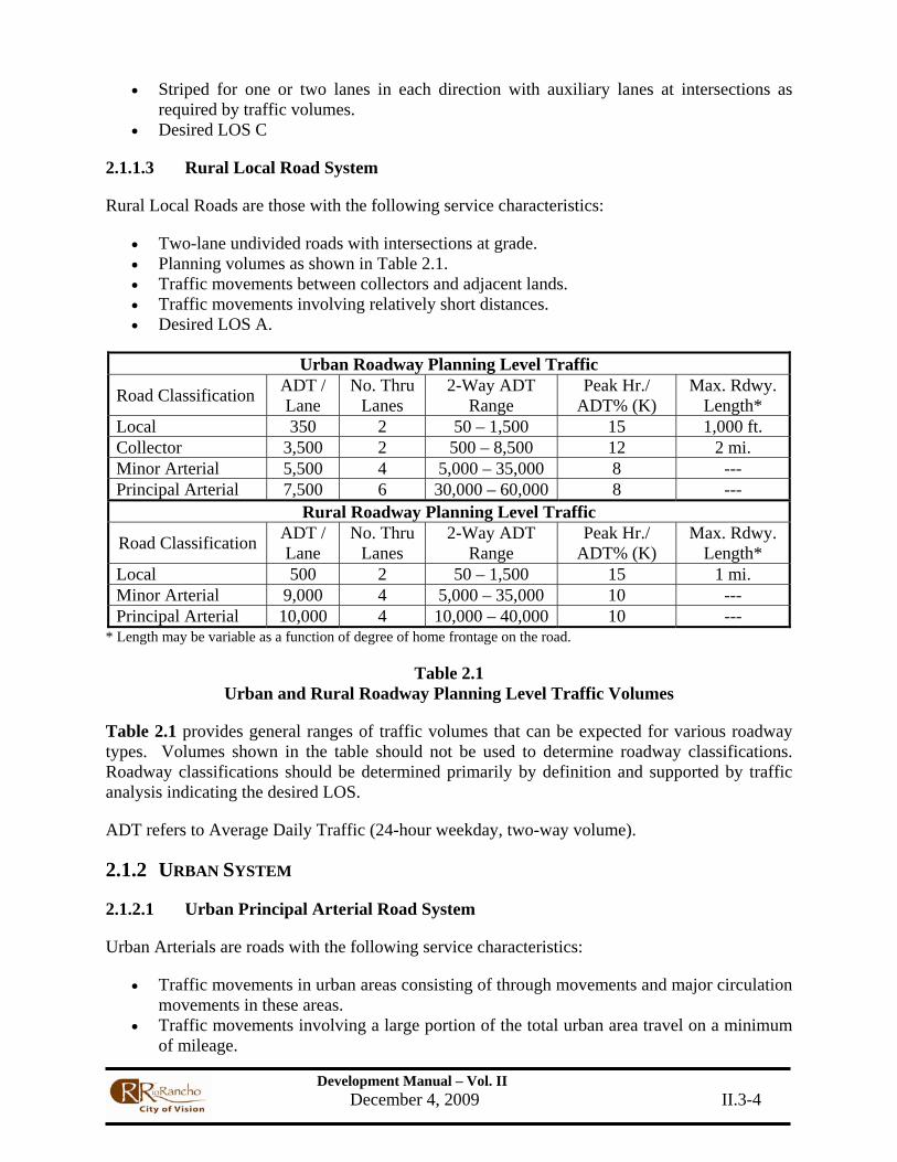
• Two-lane undivided roads with intersections at grade. • Planning volumes as shown in Table 2.1. • Traffic movements between collectors and adjacent lands. • Traffic movements involving relatively short distances. • Desired LOS A.
Urban Roadway Planning Level Traffic
Road Classification ADT / Lane
No. Thru Lanes
2-Way ADT Range
Peak Hr./ ADT% (K)
Max. Rdwy. Length*
Local 350 2 50 – 1,500 15 1,000 ft. Collector 3,500 2 500 – 8,500 12 2 mi. Minor Arterial 5,500 4 5,000 – 35,000 8 --- Principal Arterial 7,500 6 30,000 – 60,000 8 ---
Rural Roadway Planning Level Traffic
Road Classification ADT / Lane
No. Thru Lanes
2-Way ADT Range
Peak Hr./ ADT% (K)
Max. Rdwy. Length*
Local 500 2 50 – 1,500 15 1 mi. Minor Arterial 9,000 4 5,000 – 35,000 10 --- Principal Arterial 10,000 4 10,000 – 40,000 10 ---
* Length may be variable as a function of degree of home frontage on the road.
Table 2.1 Urban and Rural Roadway Planning Level Traffic Volumes
Table 2.1 provides general ranges of traffic volumes that can be expected for various roadway types. Volumes shown in the table should not be used to determine roadway classifications. Roadway classifications should be determined primarily by definition and supported by traffic analysis indicating the desired LOS.
ADT refers to Average Daily Traffic (24-hour weekday, two-way volume).
2.1.2 URBAN SYSTEM
2.1.2.1 Urban Principal Arterial Road System
Urban Arterials are roads with the following service characteristics:
• Traffic movements in urban areas consisting of through movements and major circulation movements in these areas.
• Traffic movements involving a large portion of the total urban area travel on a minimum of mileage.

Development Manual – Vol. II December 4, 2009 II.3-5
• Posted speeds between 45 mph and 55mph. • Divided four-lane or six-lane roads. • Planning volumes as shown in Table 2.1. • Striped for one or two lanes in each direction with a median and exclusive turn lanes
where applicable. • Desired LOS D
2.1.2.2 Urban Minor Arterial Road System
Urban Minor Arterials are roads with the following service characteristics:
• Traffic movements in urban areas consisting of major circulation movements within these areas, with more emphasis on land access than major roads.
• Traffic movements do not penetrate residential neighborhoods. • Traffic movements at moderate speeds with partially controlled access facilities. • Undivided or divided (divided preferred) two or four-lane with intersections at grade. • Planning volumes as shown in Table 2.1. • Striped for two or three lanes in each direction with a median and exclusive turn lanes
where applicable. • Desired LOS C
2.1.2.3 Urban Collector Road System
Urban Collector Roads are roads with the following service characteristics:
• Traffic movements in urban areas consisting of both land access service and traffic circulation.
• Traffic movements subject to high levels of median and side friction. • Traffic movements penetrate local areas.
o Development may front directly on the road. o Has more than 10 uncontrolled access points per mile on one side. o Local areas include residential neighborhoods, commercial, and industrial areas.
• Traffic capacity for an Urban Major Collector Road is limited not by the typical capacity of the road section but instead by the desirability of maintaining acceptable traffic levels by the use of continuous center left turn lanes rather than intermittent left-turn lanes. Urban 'Minor' Collector Roads maintain acceptable traffic levels that will not affect residential neighborhoods adversely. Planning volumes as shown in Table 2.1.
• Desired LOS C (major collector) and LOS B (minor collector).
2.1.2.4 Urban Local Road System (Residential)
Urban Local Roads are those with the following service characteristics:
• Two-lane undivided roads with intersections at grade with frequent driveway access. • Planning volumes as shown in Table 2.1. • Traffic movements between adjacent lands and collectors or other roads of higher
classification.

Development Manual – Vol. II December 4, 2009 II.3-6
• Traffic movements over relatively short distances, less than 8 blocks long in most cases. • Desired LOS A
2.1.2.5 Cul-De-Sacs and Turnarounds
Cul-de-sacs and Turnarounds are roads with the following service characteristics:
• Traffic movements enter and exit at only one end of the road. • Traffic movements having a turnaround.
2.1.2.6 Private Ways
Private Ways are roads with the following service characteristics:
• Two-lane undivided roads with intersections at grade • Traffic Movements are only to service a limited number of homes or businesses. • Private Ways are not located within public right of way. • Roads are not considered part of the CORR road system.
2.2 STREET LOCATION/NAMING
2.2.1 STREET LOCATION
Streets must conform in character, location and arrangement to adopted plans. Governing plans may be the approved neighborhood site plan, site development, sector plans, or adopted future street lines. The Department of Development Services should be consulted for information regarding applicable plans for areas under design consideration.
Proposed street arrangements must provide for the continuation of existing principal streets or appropriate projections thereof if not otherwise governed by an adopted plan. No half street improvements are allowed within the City of Rio Rancho. All proposed four lane roadway improvements must be continuous for a total length, intersection to intersection, and approved by the City Engineer.
2.2.2 STREET NAMING
The naming of streets shall be coordinated with the City of Rio Rancho Development Services Department. Street naming shall be in accordance with the ordinances and guidelines set by Development Services.
2.3 DESIGN HOUR VOLUMES
2.3.1 DESIGN YEAR
The Design Year for future traffic volumes is the year when construction/buildout is complete. The Horizon Year is the calendar year rounded off to the nearest 5-year increment after buildout. For some regionally significant transportation Corridors, the Traffic Engineer may designate the Horizon Year as the Horizon Year in the currently adopted Metropolitan Transportation Plan. The MRCOG model will be used for projecting background traffic models through the given

Development Manual – Vol. II December 4, 2009 II.3-7
design and horizon years. The Design Engineer will confirm the design year for a project before starting the design process.
2.3.2 ADJUSTMENT TO DESIGN YEAR ADT VOLUMES
For some roadway design projects, adjustments will be required to the volumes projected by MRCOG. Adjustments will be required in anticipation of major land developments or significant changes in nearby street and/or highway networks that will affect future traffic volumes expected on the roadway under design. Adjustments in traffic volumes for major land developments will follow the City of Rio Rancho Traffic Impact Study Procedures as referenced in SECTION 2, SUBSECTION 4.0, TRAFFIC IMPACT STUDY PROCEDURES of this Chapter. Adjustments for other impacts shall be approved by the City Traffic Engineer before being undertaken by the Design Engineer.
2.3.3 DESIGN HOUR VOLUME
The Design Hour Volume (DHV) is the traffic volume used to determine the number of traffic lanes on the roadway. Use the following formula to determine the DHV:
DHV = ADT x K
Where:
DHV = design hour volume of traffic (total, 2-way) ADT = average 24-hour weekday, 2-way volume of traffic K = ratio of design hour volume to ADT
(See Table 2.1 for K values to use for rural and urban roadway classifications.)
The number of lanes for each direction of traffic for an interim roadway is determined by the traffic impact analysis. However, the interim roadway shall be designed for conversion to the ultimate section determined by classification.
For special activity centers such as recreational areas, factories, sports arenas, etc., other values of the above factors will be used. It is also recognized that special traffic conditions may or will exist that require modification of the above factors. In these two sets of cases, the different factors must be documented and approved for use by the City Traffic Engineer.
2.3.4 TURNING MOVEMENT PERCENTAGES
At major intersections and at driveways leading to major activity centers, the design hour turning volumes are important in determining the intersection capacity, resulting number of lanes, and the storage length for exclusive turning lanes required for each approach. For intersections being reconstructed and that are in fully developed areas, existing turning movement percentages will be collected in the field and are assumed to be the same for the future design year. For new intersections or for those significantly impacted by new land developments or major changes in nearby street/highway networks, existing and projected traffic data along with engineering judgment will be used to reassign vehicle trips on nearby street networks to derive the turning movements at project intersections.

Development Manual – Vol. II December 4, 2009 II.3-8
Turning movements must be analyzed for both a.m. and p.m. peak hours at project intersections so that the maximum turning or through volumes can be determined for each approach. In the absence of other data, it can generally be assumed that the 'background' street network intersection turning movements will be opposite and equal for the a.m. and p.m. peak hours. It is important for the Design Engineer to obtain sufficient existing traffic counts by hourly variation to accurately identify and quantify project intersection turning movement volumes for the design year.
2.3.5 OTHER TRAFFIC VOLUME REDUCTION FACTORS
Vehicle trip (traffic volume) reductions for future transit ridership or other transportation modes are generally not permitted. Reductions for "passer-by or' diverted' trips are allowed as per the Institute of Transportation Engineers (ITE) Trip Generation Manual (latest revision) but must first be approved by the City Traffic Engineer. Trip reductions for special land uses utilizing travel demand management (TDM) strategies will be considered on a case-by-case basis. However, the factors used must be fully and accurately documented to the City's satisfaction.
2.3.6 CAPACITY ANALYSIS
Software using the current Highway Capacity Manual (HCM) procedures will be used to determine the capacity and resulting number of lanes for roadway design project street sections and intersections. For rural street sections with existing or planned traffic signals more than a mile apart, the appropriate section of the HCM will be used. For urban or suburban areas where traffic signals are at or less than a mile apart, it will be assumed that the signalized intersection capacity will control the design of the roadway segments.
The number of through lanes on street sections must be consistent with the number of through lanes at adjacent intersections. For capacity and lane determination, major intersections are assumed to be signalized for the design year. The signalized intersection section of the HCM will be used for the analysis. The default values of the peak hour factor (PHF), percentage of trucks, and saturation flow rate shall be used. Other input criteria will be those equal to existing or future traffic conditions and approved by the City Traffic Engineer.
2.3.7 FUTURE TRAFFIC VOLUMES
Future traffic volumes shall be used to ensure that the road has enough traffic carrying capacity. The general unit of measure for traffic on a road is the ADT, the total volume of traffic in a given time period divided by the number of days in that time period. The future ADT shall be derived from the MRCOG forecast model and the engineer's judgment of growth patterns in the area.
The traffic volume during a period of time shorter than a day shall be used for design purposes, reflecting peak hour periods. Reference Table 2.1 for the K-values for rural and urban roadway classifications. For roads with unusual or highly seasonal fluctuation in traffic volumes, the 30th highest hour of the design year should be used.
The directional design hour volume is the traffic volume for the rush hour period in the peak direction of flow. Use directional distribution factors based on existing traffic counts. If this information is not available it should be assumed that 60% of the traffic is going in one direction. Reference Table 2.1 for design volume threshold per hour per lane. For a more detailed analysis

Development Manual – Vol. II December 4, 2009 II.3-9
of intersection and road capacity, procedures as described in the intersection portion of this chapter and the latest version of the HCM should be used.
2.4. TRAFFIC IMPACT STUDY PROCEDURES
This policy is to provide for consistency in the preparation of traffic impact studies using certain established criteria. It has been prepared to assist consultants, developers, and others interested in evaluating traffic impacts within the City of Rio Rancho’s jurisdiction.
Developers and their engineering consultants are invited to discuss proposed projects with the Traffic Engineering Staff prior to beginning the analysis. This is to enable discussion and determination of parameters to be used and to open communications between City staff and the developer or consultant. Such communication will help in creating land uses with traffic characteristics that are in the entire community's best interests.
2.4.1 TRANSPORTATION IMPACT ANALYSIS (TIA) REQUIREMENTS
A TIA studies the effects of new development on the city’s transportation infrastructure, and helps the city determine what changes, if any, are necessary to minimize those effects. It is also used to determine how much capacity a new road within a development needs to appropriately serve its needs.
Preparing a TIA should begin as early as possible in the development process to avoid costly design changes that might be required after city staff completes their review. The applicant and the applicant’s engineer are encouraged to consult with staff prior to preparation of the TIA to reduce report revisions and review time. The primary concerns to be addressed in the TIA are site access, impact on the existing roadway system, and what construction is necessary to mitigate both the on-site and off-site impacts. The site design should be tailored to the traffic requirements, and the city reserves the right to require changes to the access points to better serve the transportation system.
2.4.1.1 Traffic Impact Study Thresholds
The City of Rio Rancho has developed thresholds that may be used as a general guideline to determine if a traffic impact study will be required for a given development proposal. Though a development may meet these thresholds, the city reserves to right to require a TIA in some cases, such as, but not limited to, creating safety or neighborhood traffic concerns and developments that generate a high volume of truck traffic. These thresholds are based upon the specific land use generating less than 100 peak hour trips during either the AM or PM peak design hours. If the site generates less than 100 peak hour trips, the requirement for a traffic impact study may be waived. In this case, only a trip generation report need be submitted.

Development Manual – Vol. II December 4, 2009 II.3-10
ITE Code Land Use Units Threshold
130 Industrial Park SF 74,000 140 Manufacturing SF 144,000 150 Warehousing SF 128,000 210 Single Family Housing DU 92 220 Apartment DU 147 230 Residential Condominium or Townhouse DU 184 310 Hotel Rooms 168 320 Motel Rooms 240 445 Multiplex Movie Theater Screens 4 445 Multiplex Movie Theater Seats 990 492 Health/Fitness Club SF 23,000 710 General Office SF 18,000 720 Medical-Dental Office Building SF 28,000 812 Building Materials and Lumber Store SF 20,000 815 Free Standing Discount Store SF 19,000 820 Shopping Center (General Retail) SF 6,000 841 New Car Sales SF 40,000 843 Auto Parts SF 14,000 850 Supermarket SF 6,000 853 Convenience Market with Gasoline Pumps Pumps 5 870 Apparel Store SF 17,000 880 Pharmacy/Drug Store without Drive Through SF 11,500 912 Drive In Bank SF 2,000 931 Quality Restaurant SF 13,000 932 High Turnover Restaurant SF 8,000 934 Fast Food Restaurant with Drive Through SF 1,800 944 Gasoline/Service Station Pumps 7 945 Gasoline Station with Convenience Store Pumps 7 946 Gasoline Station with Convenience Store and Car Wash Pumps 7
All land uses not listed above or projects that contain a combination of land uses should be discussed with Traffic Engineering staff. They may be contacted at 896-8770.
Developments that generate 500 or more vehicle trips during either the AM or PM peak hour may require an expanded analysis. Please verify the scope with Traffic Engineering staff.
A scoping study is required for all traffic studies. The scoping study will establish the project study area, analysis years and conditions, acceptable traffic count years, trip distribution methodology, background traffic growth rate, programmed improvements, and the allowable pass-by trip percentage.
2.4.1.2 Study Area
The study area shall include all site access points, as well as any adjacent intersections. Inclusion of any additional intersections shall be determined during the scoping meeting by city staff, and may include, but are not limited to, signalized or potentially signalized locations within 2 miles of the development, residential roads that are projected to have a 25% increase in volumes, or truck routes for a development whose site traffic consists of at least 5% truck traffic.

Development Manual – Vol. II December 4, 2009 II.3-11
2.4.1.3 Trip Generation
The latest version of the ITE Trip Generation Manual shall be used for all trip generation calculations, unless more appropriate data is available. Unless otherwise stated in the scoping meeting, the average trip generation formulas or rates shall be used, with the curve equation being the preferred method when enough data is available for an accurate application (R2 approaches 1). Default pass-by rates are also to be used unless otherwise specified during the scoping meeting.
2.4.1.4 Study Time
All analysis shall be done for both AM and PM peak weekday periods. In some cases, an off-peak hour or weekend may need to be studied if the development is, or is near, an atypical traffic generator, such as a school or church.
Peak hour baseline traffic counts shall be done for all specified intersections. Existing counts may be used if less than two years old. These numbers shall be used to analyze the existing conditions.
2.4.1.6 Horizon Year
The farthest future time that the impacts of a development shall be studied is five years after completion of construction. For smaller developments, the horizon year may be moved closer to build-out.
In some cases, a historical growth rate may be obtained from MRCOG Traffic Flows Maps for the Albuquerque area. However, due to the rapidly changing infrastructure, some of the values extrapolated from the maps may not provide a good estimate for future traffic, either because of negative growth or a growth rate over 5% that cannot be sustained for a number of years. When this is the case, a background growth rate of 2.5% shall be used.
The addition of the traffic growth to the existing numbers shall be used for the horizon no-build condition. Any funded infrastructure improvements can also be used during the horizon analysis.
2.4.1.7 Methodology
All intersection analysis shall be done in accordance with Highway Capacity Manual procedures for two-way stop control, four-way stop control, roundabouts, and signals. Queuing analysis shall be done according to the Poisson negative exponential random arrival distribution, for both the 50% and 95% levels.
Level of services for all stop and signal controlled movements shall be calculated for the project completion year, no-build condition, completion year, build condition, horizon year, no-build condition, and horizon year, build condition.
Queue analysis shall be done for horizon year, no-build condition, and horizon year, build condition.
Where high volumes prevent adequate operation of a two-way stop controlled intersection (LOS E or worse), a signal warrant analysis shall be done according to MUTCD standards. If the intersection consists of two roads with one through lane in each direction, then the theoretical performance of a roundabout shall also be calculated.
Estimated ADTs for all system streets shall be included in the report.

Development Manual – Vol. II December 4, 2009 II.3-12
In some cases, a crash analysis will be requested by city staff to help identify unsafe conditions in the project area that may be exacerbated by an increase in traffic.
2.4.1.7 Recommendations
LOS D is considered acceptable for most situations, however if development in the surrounding area is sparse, the city may require that intersections function more efficiently in the near future to allow for later growth. If a development recommends improvements that only allow LOS D, the city may require additional work to maintain good operation.
The City currently requires that all new developments’ access points and any necessary auxiliary lanes follow the design guidelines in the NMDOT State Access Management Manual (SAMM), unless there is an adopted policy for an adjacent corridor that supercedes the SAMM.
All internal roads shall be sized appropriately for their projected traffic. In general, the city will require two lanes in each direction only for roads with a projected ADT above 18,000 vehicles, so long as intersections operate at LOS D or better.
Development Manual – Vol. II December 4, 2009 II.3-13
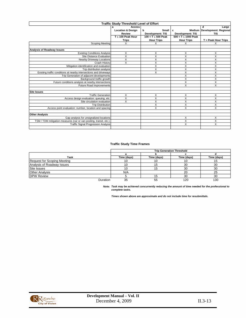
a Access Location & Design
Reviewb Small
Development: TISc Medium
Development: TIS
d Large Development: Regional
TIST ≤ 100 Peak Hour
Trips100 < T ≤ 500 Peak
Hour Trips500 < T ≤ 1000 Peak
Hour Trips T > Peak Hour TripsScoping Meeting X X X X
Analysis of Roadway IssuesExisting Conditions Analysis X X X X
Site Distance Evaluation X X X XNearby Driveway Locations X X X X
Crash History X X X XMitigation identification and evaluation X X X
Trip distribution analysis X X XExisting traffic conditions at nearby intersections and driveways X X X
Trip Generation of adjacent developments X XBackground traffic growth X X
Future conditions analysis at nearby intersections X XFuture Road Improvements X X
Site IssuesTraffic Generation X X X X
Access design evaluation: queuing, etc. X X X XSite circulation evaluation X X X X
Trip Distribution X X XAccess point evaluation: number, location and spacing X X X
Other AnalysisGap analysis for unsignalized locations X X
TSM / TDM mitigation measures (car or van pooling, transit, etc.). X XTraffic Signal Progression Analysis X X
a b c dTask Time (days) Time (days) Time (days) Time (days)
Request for Scoping Meeting 10 10 10 15Analysis of Roadway Issues 10 15 30 30Site Issues 10 15 30 30Other Analysis N/A 20 25DPW Review 5 15 30 30
Duration 35 55 120 130
Note:
Times shown above are approximate and do not include time for resubmittals.
Traffic Study Threshold Level of Effort
Traffic Study Time Frames
Task may be achieved concurrently reducing the amount of time needed for the professional to complete tasks.
Trip Generation Threshold
Development Manual – Vol. II December 4, 2009 II.3-14
3. Design Procedure
3.1 BASIC CRITERIA
3.1.1 ROAD CLASSIFICATION AND TYPICAL SECTION
The road classification shall be identified in the Concept Report or Project Scope of Work. If the classification is not identified, the Design Engineer must submit a classification for approval to the City Project Manger.
3.1.2 DESIGN VEHICLE
The design vehicle is the largest vehicle likely to use the road with considerable frequency or a vehicle with special characteristics that must be considered in designing the road. The design vehicle will affect the radii at intersections and the radii of turning roadways. It will also affect the climbing lane requirements on two lane roads. Unless otherwise specified, all arterial and collector roadways and intersections will be designed to accommodate a WB-50 design vehicle. All residential roadways shall be designed to accommodate a Single Unit (SU) design vehicle. Design vehicles shall be as defined in the AASHTO publication, A Policy on Geometric Design of Highways (current edition).
3.1.3 DESIGN FOR FUTURE TRAFFIC VOLUMES
The primary design consideration for roadways is the handling of vehicular traffic. When streets are built or reconstructed, they will be designed with sufficient traffic handling capacity to accommodate a future level of traffic volumes. SECTION 2, SUBSECTION 3.0 DESIGN HOUR VOLUMES and SECTION 2, SUBSECTION 4.0 TRAFFIC IMPACT STUDY PROCEDURES describe in greater detail the process that shall be followed in determining the capacity of roadways and intersections used in the design process.
While the functional classification approved for a roadway will govern the basic cross sectional elements, additional through or left turn lanes, auxiliary right turn lanes, acceleration lanes, and similar design features may be required. The designer should do a detailed capacity analysis to determine the need for additional or auxiliary lanes.
3.1.4 TOPOGRAPHY
The topography of the area shall be determined by a site visit and available topographic maps. The terrain shall be classified as level, rolling, or mountainous. Level terrain is when roadway sight distances are or could be made adequate without major construction requirements. This generally includes short grades of no more than 1 or 2 percent. Rolling terrain is when natural slopes consistently rise and fall with grades of up to 6 percent for lengths of 700 feet. Mountainous terrain is when changes in the ground's elevation with respect to a road are abrupt. Mountainous terrain has greater than 15 percent slopes on the U.S.G.S. 7.5-Minute Series Maps.

Development Manual – Vol. II December 4, 2009 II.3-15
3.1.5 DEVELOPMENT OF PLANS AND SPECIFICATIONS
Project design and construction, unless otherwise indicated, shall be in accordance with the latest edition and current revision of the following publications:
• APWA Uniform Standard Specifications and Details for Public Works Construction as distributed by American Public Works Association New Mexico Chapter.
• Manual on Uniform Traffic Control Devices for Streets and Highways as distributed by the U.S. Department of Transportation, Federal Highway Administration.
• A Policy on Geometric Design of Highways and Streets as distributed by the American Association of State Highway and Transportation Officials (AASHTO).
• Roadside Design Guide as distributed by the American Association of State Highway and Transportation Officials (AASHTO).
• Highway Capacity Manual and the current Highway Capacity Software, as distributed by the Transportation Research Board.
• Drainage Design Manual, as distributed by the City of Rio Rancho. • Standard Specifications for Highway and Bridge Construction as distributed by the New
Mexico Department of Transportation (NMDOT). • Information Guide for Roadway Lighting as distributed by the American Association of
State Highway and Transportation Officials (AASHTO). • Guide for Development of Bicycle Facilities, as distributed by AASHTO.
3.1.6 ALTERNATIVE MULTI-MODAL CROSSINGS
CORR will incorporate trail crossings of the MRCOG Long Range Bikeways Systems Map in the design and construction of roadways. CORR will consider all trails, shared-use paths, and other multi-modal facilities proposed by developers or other agencies in the design and construction of roadways. The type of crossing will be determined on a case-by-case basis. Grade separated intersections at major road crossings should be considered whenever feasible. Guidelines for crossings will comply with the latest edition of the AASHTO Guide to the Development of Bicycle Facilities, MRCOG Long Range Bikeways Systems Map, or other agreed upon national or local design guidelines or standards.
3.1.7 TIME LIMITATION OF APPROVAL
The City approval of residential developments, commercial developments, and road construction plans shall be valid for a time period of one (1) year. Plans NOT under construction within this time period are to be resubmitted and approved by the City prior to construction.
3.2 SPECIAL PROVISIONS AND ENGINEER’S ESTIMATE
3.2.1 SPECIAL PROVISIONS
3.2.1.1 Residential/Commercial Development
The Design Engineer shall prepare Special Provisions for construction items not contained in or adequately covered by the APWA New Mexico Standard Specifications and Details for Public Works Construction as needed. Special provisions shall insure that each construction item is

Development Manual – Vol. II December 4, 2009 II.3-16
clearly defined and all material and construction requirements are identified. Special Provisions shall be written and arranged in the same format as the APWA New Mexico Standard Specifications and Details for Public Works Construction. The Design Engineer shall prepare and submit sealed Special Provisions. Special provisions shall be included with proposed construction documents submitted for review.
3.2.1.2 Capital Improvement Projects (CIP)
The Design Engineer shall prepare Special Provisions for construction items not contained in or adequately covered by the APWA New Mexico Standard Specifications and Details for Public Works Construction or the New Mexico Department of Transportation (NMDOT) Specifications depending on the funding source and requirements for the project. Special provisions shall insure that each construction item is clearly defined and all material and construction requirements are identified. Special Provisions shall be written and arranged in the same format as the document to which the special provisions are based on (i.e. NMDOT or APWA).
The Design Engineer shall provide The City’s Project Manager with sealed and signed original Special Provisions along with an electronic copy. The submitted electronic copy shall be in a format acceptable to the City. The Design Engineer shall prepare and submit sealed addenda that may be required to clarify or correct the Construction Contract Documents (Construction Plans, Special Provisions and Bidding Form).
3.2.2 ENGINEER’S ESTIMATES
3.2.2.1 Residential/Commercial Developments
The Developer/Design Engineer shall provide the City Engineering Section Manager for Development Review or their designee with an Engineer’s Estimate of Probable Cost at final submittal of the construction documents. The estimate shall contain a comprehensive itemized listing of individual project components with quantities, estimated unit costs and extended total costs identified for each item. Unit costs shall accurately reflect current market costs. Supporting documentation shall be provided to the City upon request.
An example of the preferred formats for the Estimate of Probable Cost for Onsite, Offsite, and Deferred Improvements can be found at the following CORR website: www.ci.rio-rancho.nm.us.
3.2.2.2 Capital Improvement Projects (CIP)
For City Capital Improvement Projects, cost estimates shall be formatted as a fee schedule with City designated bid item numbers and descriptions. The City of Rio Rancho “Bid Item List” can be found on the City website at: http://ci.rio-rancho.nm.us/index.asp?nid=352
When the City provides information on past bid results, it is the Design Engineer's responsibility to evaluate the appropriateness of the information, prior to using the information in the Engineer's Estimate. An example of the preferred format for Lump Sum and Unit Pricing Bids can be found at the following CORR website: http://ci.rio-rancho.nm.us/index.asp?nid=352
An electronic copy of this format can be obtained from the City Project Manager.

Development Manual – Vol. II December 4, 2009 II.3-17
3.3 SURVEY AND DATA ACQUISITION
The survey must be supervised by a professional land surveyor registered in the state of New Mexico. This section contains general survey requirements. For specific topography and notation requirements for construction documents refer to CHAPTER 2.7 - Submittal Requirements.
3.3.1 TOPOGRAPHICAL FEATURES
All topographic features and elevations (along the project road and crossroads alignments) shall be recorded. Topographic features and elevations shall extend a minimum distance of 15 feet beyond any anticipated new right-of-way. Any planimetric feature and/or elevation that could affect or be affected by the design shall be recorded and shown on the plans. For example, improvements such as houses, drainage ways, ditches, railroad tracks, high voltage power poles, etc., shall be shown. Distances to power poles, signs, trees, fences, and similar obstructions shall be measured to the face of the object closest to the survey centerline. If a survey centerline is not defined, it shall be assumed as the proposed construction centerline alignment. Sufficient dimensions of the object must be recorded and shown on the plans as appropriate for correct depiction. Floor elevations shall be shown on the plans for houses and buildings within 20 feet of the project.
Elevations beyond the proposed right-of-way line must be recorded for driveways that may require alterations beyond the right-of-way. Elevations shall also be obtained for all parking areas on adjacent property to ensure that the property will properly drain in conjunction with new roadway grades. The Design Engineer is responsible for maintaining proper drainage from adjacent properties. The plans will be returned if, in the City Project Manager’s opinion, the information submitted is not adequate to properly review the proposed grades and drainage design.
Field measurements for utility facilities shall include: identification of the direction, diameter, material, and inverts elevations of all pipes associated with junction structures, manholes, and culverts; identification of the manhole rim and invert elevations; water valve operating nut and valve box cover elevations. When utility supplied buried facility maps are incomplete or do not accurately identify utility locations, New Mexico One Call, Inc. should be contacted (505-260-1990 or 1-800-321-2537) and markings shall be part of the topographic information obtained and included on plan base maps. The designer shall not attempt via notes or omission to pass the responsibility to locate utilities through to the contractor or City. The designer shall pothole utilities if necessary.
All survey data shall be in accordance with NAVD88. Topographic features shall be measured as follows:
1) Distance to all topographic features, except to valve boxes and manholes, shall be measured to the near the face of feature.
2) Distance to all valve box covers and manhole covers shall be measured to the center of the cover. If the manhole has been constructed with an offset, the offset shall be indicated.

Development Manual – Vol. II December 4, 2009 II.3-18
3.3.2 TRAFFIC RELATED FEATURES
Existing edges of pavements, major drives, traffic signals, traffic striping, and traffic signs shall be surveyed to 500 feet beyond each end of the project limits.
3.3.3 ELEVATION DATUM
North American Vertical Datum of 1988 (NAVD 88 - National Geodetic Survey) datum shall be used unless otherwise authorized by the City Engineer. The elevation datum shall be derived from First Order benchmarks tied to one NGS or City monument and to any adjacent ongoing project, adjacent city datum, and to any datum used by utilities within the project area. The elevation of existing monuments along the project corridor shall also be obtained but typically not called out on plans as project construction benchmarks. Identify on the plans the project benchmark used to establish project elevations.
3.3.4 CONSTRUCTION BENCHMARKS
All survey monuments for street intersections, angle points, and horizontal curves necessary to the project design shall either be found in the field or set using appropriate survey equipment during construction.
At least two benchmarks on a project shall be existing City-recognized benchmark monuments. Elevations of City benchmarks will be furnished by the City of Rio Rancho Department of Public Works. Any temporary benchmarks that are used shall be shown on the project construction documents (i.e. location, elevation, description, etc).
A maximum permissible closure in feet of (0.05) x (square root M), where M is the total distance run in miles, shall be maintained. The results of the closed bench circuit shall be balanced using acceptable surveying methods.
3.3.5 SURVEY CROSS SECTIONS
For projects in which an existing road will be widened using the existing cross slope of the road survey cross sections shall be taken at least every 100 feet along tangents, 50 feet along curves, with additional sections taken at locations where the terrain deviates, as necessary. Horizontal limits shall extend 15 feet beyond proposed right-of-way left and right, with right-of-way elevations given at average natural ground.
All ditch flow lines, tops of banks, tops of linings, high water marks, culverts, inverts, manhole inverts, tops of headwalls, building slab elevations, and similar features shall be obtained and clearly noted.
Existing pipe culverts, washes, and ditches shall be profiled along their existing alignments and the skew angles and angle points identified. The widths of ditches, berms, and similar structures shall be identified. Major drainage features shall require additional survey cross sections, both upstream and downstream of the project 300 feet beyond the project limits. Intersecting roadways shall require additional survey cross sections 100 feet beyond the project limits. Project survey cross sections shall extend 100 feet beyond the end and beginning of the proposed project improvements.

Development Manual – Vol. II December 4, 2009 II.3-19
Note: The above cross section guidelines may be disregarded in instances where the project topography is obtained through an aerial company, approval should be obtained from the City Project Manager and the existing roadway will be removed and replaced. However, in locations where the proposed improvements will tie into existing improvements additional survey field shots should be obtained as described above to ensure smooth engineered transitions.
3.3.6 DATA ACQUISITION
The Design Engineer shall research materials such as record drawings (as-built plans), utility plans, and other data and show pertinent information including utility easements on the construction drawings.
3.4 RIGHT OF WAY
The Preliminary Plat and/or Concept Report will generally identify the anticipated basic right-of-way for individual projects. It is understood that the design process will refine the concept by identifying additional requirements and any construction, drainage, or slope easements required. Permanent right-of-way, including the size of triangles at intersections, shall be recommended at the time of initial submittal. The location and configuration of construction, drainage, slope and temporary easements, including any required for detours, shall be shown. The plans shall show and clearly identify both existing and new right-of-way and easement configurations.
The Design Engineer shall furnish a base map to the City Project Manager showing existing and new right-of-way required for the proposed improvements.
3.5 UTILITIES
Relocation of existing utilities shall be avoided, except where necessary due to construction or drainage requirements. Design of culverts and/or storm drain systems should avoid or minimize any disruption of utility service. The location of existing and new underground utilities and culverts shall be appropriately shown in paving profiles, culvert profiles, and storm drain profiles. All above ground utilities and signal poles shall be offset behind future sidewalk in urban areas. In rural areas, above ground utilities shall be located as close to the right-of-way line as is practical.
3.5.1 COORDINATION WITH UTILITIES OWNERS
3.5.1.1 Residential/Commercial Developments
Close coordination with utility owners is very important to new developments and roadway projects to insure timely relocations or installation of new facilities. The design engineer shall research utility information, determine the location and ownership of all utilities within the project limits and resolve each design issue associated with utilities. When two or more utility owners with the same type of facility exist within the project limits, the plans shall indicate the owner associated with each installation. The construction documents shall clearly identify any conflicts or relocations that will need to take place within the project limits. Dry utilities shall be located in the Public Utility Easement (PUE) and wet utilities shall be located in the roadway per City of Rio Rancho standards.

Development Manual – Vol. II December 4, 2009 II.3-20
The Design Engineer shall furnish plan sets to each utility owner impacted by the project. Direct contact with utility company for design coordination and land conflict resolution will be coordinated with the City Project Manager unless the conflict is a streetlight or wet utility in which case the project manager will represent the City. The Design Engineer shall record minutes of all meetings and provide the City with copies of all minutes and correspondence directly received by the Design Engineer.
3.5.1.2 Capital Improvement Projects (CIP)
The Consultant shall use the City of Rio Rancho Utility Conflict Letter found in Appendix D to initiate and record the review of the proposed improvements with the appropriate utility owners and municipalities. An electronic Copy of this letter can be obtained from the City Project Manager.
3.6 TRAFFIC DESIGN
3.6.1 SIGNING & STRIPING DESIGN
The following information outlines the signing and pavement markings design procedures for use on the City of Rio Rancho Street System.
The information presented is consistent with the latest edition of the Manual on Uniform Traffic Control Devices for Streets and Highways (MUTCD) and the City of Rio Rancho Signing and Marking Manual.
The intent of the following material is to establish standard procedures that will be used by traffic engineering consultants when designing signing and pavement markings for City of Rio Rancho projects.
3.6.2 COORDINATION WITH THE CITY
3.6.2.1 Project Information
Prior to meeting with the City of Rio Rancho Department of Public Works, the Traffic Engineering member of the Project Design Team should obtain or develop a description of the project showing all proposed improvements and the project limits. The Traffic Designer should become familiar with all aspects of the project.
3.6.2.2 Meeting With the City of Rio Rancho Department of Public Works
The Traffic Designer shall meet with the City of Rio Rancho Department of Public Works project manager prior to beginning the pavement marking and signing design to discuss the project in detail. This discussion should address all applicable pavement marking and signing related items. Examples are listed below.
1. Current design standards that will control the design shall be identified. 2. Verify which pavement marking materials are to be used. 3. Raised pavement markers will be used only when directed to do so by the City. When
they are used, they will delineate lane lines, centerlines, two-way left turn lanes, island

Development Manual – Vol. II December 4, 2009 II.3-21
noses and fire hydrant locations, unless otherwise directed by the Department of Public Works.
4. Verify that traffic signs will use the following criteria:
• All sign posts shall be square tube perforated sign posts. • Use street light poles to mount signs when possible. • Signs to be installed per City of Rio Rancho Standard if available.
5. One of the most important elements controlling the pavement marking design is the design speed for the section of roadway and the speed limit that will be posted. The Traffic Designer shall verify the project’s design speed and posted speed limit.
6. Clarify the limits of the project and determine how the new design will match into the existing roadway.
7. A product of this meeting will be the identification of the primary City of Rio Rancho Department of Public Works contacts for the project.
8. The Traffic Designer shall supply the Department of Public Works with the overall project schedule.
9. At this meeting, City staff will identify any specialty signing in the area of the project or any unusual roadway pavement marking needs (e.g. hospitals, park and ride facilities, freeway trailblazing, libraries, bike lanes, etc.).
3.6.2.3 Post Meeting Communication
The Traffic Designer shall send to the City of Rio Rancho Department of Public Works contact any follow-up material that may be needed, particularly information that modifies or changes the concepts that were discussed during the original pre-design meeting. For example, the Traffic Designer will:
1. Prepare and distribute meeting minutes to all concerned parties. 2. Send project scope changes and design criteria changes to the project contact in the City’s
Department of Public Works project manager 3. Update the project schedule and proposed submittal dates. 4. If necessary, schedule a meeting with City of Rio Rancho to discuss review comments.
3.6.3 FIELD REVIEW
3.6.3.1 Site Visit
The Traffic Designer shall visit the project site to inventory and identify physical features that may impact the pavement marking and signing designs. These features will include existing street width; curb/gutter and sidewalk locations; median configurations and dimensions; and, trees or bushes that may affect sign visibility.
3.6.3.2 Site Inventory
The Traffic Designer shall perform an inventory of existing signing and existing pavement markings. This inventory shall record the following:
1. Sign size, sign material, and the general condition of the sign.
Development Manual – Vol. II December 4, 2009 II.3-22
2. Sign type and legend. 3. Posted speed limit(s). 4. Specialty signs throughout the project limits. 5. Sign post type, foundation type and label number, if available. 6. The pavement marking configuration at the location where the new street improvements
will meet or match the existing street (e.g. lane widths, median treatment, bike lane or shoulder treatments).
7. Driveway locations and the operation of driveways. For example, are turning movements being restricted at a driveway, is there unique channelization that may have to be modified or reinstalled, and will sight distance at the new driveways be impacted by signing and/or landscaping?
8. Side street pavement markings and signing. Will stop signs, street name signs, stop bars, etc., need to be relocated or replaced?
3.6.3.3 Existing Roadway
While reviewing the existing conditions where the new street improvement project will match into the existing street, the Traffic Designer will need to determine if additional information beyond the street improvement project limits will be needed in order to make the transition from existing to new.
3.6.3.4 Miscellaneous Items
1. Landscaping features that may interfere with installation or visibility of signs. 2. Existing electrical and traffic signal cabinets and street lights within the project limits that
will remain.
3.6.4 EARLY TRAFFIC ENGINEERING INPUT INTO GEOMETRIC DESIGN
3.6.4.1 Traffic Engineering Input
The Traffic Designer should be an early, active member of the Project Design Team and should provide information and early input to the development of the project, as follows:
1. Provide the design team with criteria that will control lateral deflections (lane shifts) in the street and in the pavement markings. Deflections shall be designed using the formulas found in the latest edition of the MUTCD.
2. Assist in defining length of roadway tapers. Street improvements should be designed so travel lane tapers meet the criteria as determined using the formulas found in the MUTCD described in item 1 above.
3. Assist in defining length of taper for lane drops using the same MUTCD criteria. In addition, sign placement for lane drops should be in compliance with the criteria identified in MUTCD, latest edition.
4. The Traffic Designer shall assist in determining the lengths of storage for left or right turn lanes.
5. For urban principal arterials posted at 45 mph or higher, turn bays shall have adequate storage length for a 95th percentile queue according to the Poisson distribution, or be 370 feet plus the appropriate taper, whichever is greater.

Development Manual – Vol. II December 4, 2009 II.3-23
Additional transportation design requirements can be found in SECTION 4 - GEOMETRIC DESIGN CRITERIA of this Chapter.
3.6.5 LIGHTING AND SIGNING
3.6.5.1 Lighting
The policy of the City is that principal arterial streets be lit to Illuminating Engineering Society of North America (IESNA) standards for arterial streets. An analysis shall be conducted identifying street light locations, wattage and height of standard required. 400 watt and /or 250 watt High Pressure Sodium (HPS) lights shall be used on principal arterials. Street lights on minor arterials, collectors and local streets, shall be located at all intersections, on cul-de-sac streets over 200' in length, at right angle turns, and at mid-block locations where block lengths exceed 500'. 250 watt HPS luminaires shall be used on minor arterials and some collectors at major Intersections. 100 watt HPS luminaires shall be used on local streets.
All designs shall be in compliance with the New Mexico Night Sky Protection Act. All luminaires shall be full cutoff fixtures. Additional shielding may be required where the adjacent terrain falls below the roadway grade.
In new subdivisions, the developer shall submit a copy of the plat with required street lighting marked to the Traffic Section Manager. This is then forwarded to Public Service Company of New Mexico (PNM) for design of the street lighting system. PNM then submits the street light plan to the City Traffic Engineer for approval. Following approval, PNM installs the streetlights in conjunction with the installation of electrical service to the subdivision. A fixed fee per streetlight is paid to PNM by the developer for the installation of these lights.
For residential neighborhood streets with speed limits under 30 mph, aluminum direct bury poles are to be installed in accordance with PNM regulations. On streets with speeds greater than 30 mph, aluminum or steel standards with breakaway bases are to be installed in accordance with PNM standards.
3.6.5.2 Signing
Street name signs are installed by the developer or contractor. A label is required to be placed on the back of all single sided signing installed by developer contractors. Each sign label will have the minimum information required by the City Traffic Section.
The roadway classification and/or design speed shall typically govern the posted speed limit. A speed limit sign shall be required at all subdivision entrances and at all areas where the speed limit changes.
All other signing within the proposed development shall be shown on the construction plans for review and approval by City Engineering.
3.6.6 INTERSECTION CONTROL AND MARKINGS
Intersection control and markings are important elements to be considered in the design of all street systems. The application of these elements to the design of streets are described in several

Development Manual – Vol. II December 4, 2009 II.3-24
of the references in this chapter. The latest edition of the Manual on Uniform Traffic Control Devices (MUTCD) shall be used to define the design of these elements.
3.6.6.1 Traffic Signals and Roundabouts
The determination of where and when traffic signals and roundabouts are to be installed shall be by the Traffic Section. This decision is based upon the evaluation of traffic conditions at an intersection in accordance with the warrants contained within the MUTCD. Excepting intersections on principal arterials, roundabouts shall be considered for every location that does meet or is anticipated to meet MUTCD criteria for a traffic signal. The Traffic Engineer will decide what the appropriate treatment is based on criteria that includes, but is not limited to, safety, efficiency, construction and operating costs, and available right-of-way. Where intersection control is not likely in the near future, right-of-way may be reserved or underground conduit and pull boxes may be constructed. If signalization will be required in the near future, foundations for the poles may be constructed. See Chapter 2.7 – Submittal Requirements.
3.6.6.2 Markings
Street markings in accordance with the MUTCD shall be included in the construction of new arterial and collector streets. For new construction, the layout of these markings need to be shown in the plans and included in the work to be performed by the contractor. The Contractor shall layout the proposed signing and striping plan in the field for verification by Public Works engineering staff.
3.6.7 TRAFFIC CONTROL, CONSTRUCTION PHASING AND CONSTRUCTION PERMITS
A critical element to maintaining safe traffic conditions during street construction activities as well as an efficient method of implementation of needed improvements is that of traffic control and phasing of construction activities. All construction activities shall address these elements through a plan which will identify the phasing of construction activities and the necessary traffic control devices in accordance with the latest edition of the Manual on Uniform Traffic Control Devices (MUTCD).
The right-of-way for a street typically accommodates many different underground and overhead utilities. The designer of a construction project needs to coordinate their activities with the other users of the right-of-way including existing and future utilities. The construction and phasing plans need to incorporate provisions for these other users.
A barricade will be required at the end of any street pavement within or at the limits of a project regardless of the class of street involved or how soon additional pavement will be placed beyond the current project limits. The only exception will be where the Traffic Manager determines that the unpaved portion of the street beyond the project limits has been and will continue to be open to and used by through traffic. The installation of the barricade must be shown on the plans and included as a part of the street improvements. The contractor must install proper warning signs as approved by the City Traffic Manager. Temporary traffic control must be approved by the Public Works Section Manager for Development The contractor must obtain a Right-Of-Way Use Permit from the Department of Public Works. The contractor must allow the City a minimum of five working days to process the permit. Temporary traffic control plans shall be prepared by persons trained and certified about the fundamental principals of temporary traffic control and

Development Manual – Vol. II December 4, 2009 II.3-25
work activities to be performed. The design, selection and placement of temporary traffic control devices for a temporary traffic control plan should based on engineering judgment.
Bollards shall be installed at the entrance to all new multi-activity trails and in park areas where special parking conditions are required. All designs must be approved by the City Traffic Engineer. Bollard installations will also be required at public utility equipment installations for special traffic control and public safety requirements. Bollards shall be constructed in accordance with the City standard details.
3.6.7.1 Residential/Commercial Development
Construction activities within the right-of-way require a Right-of-Way Use Permit. Prior to the issuance of the permit, plans must be submitted with appropriate approvals which define the construction activities, appropriate traffic control measures, and evidence of notification through the One Call System (505-260-1990) or 811 and to the Department of Public Works Engineering Section Manager for Development for review and approval.
See Appendix E for a sample of the Right-of-Way Use Permit. An official copy of this document can be obtained from the Department of Public Works front desk (891-5016).
3.6.7.2 Capital Improvement Projects (CIP)
The Consultant is required to prepare the appropriate traffic control and construction phasing plans and submit them as a part of the construction documents to the City Project Manager for review and approval.
3.7 RAILROAD CROSSINGS – RESERVED
3.8 SUBDIVISION INFRASTRUCTURE REQUIREMENTS
The following information has been provided to assist the development community in determining the extent of public infrastructure that will be required in conjunction with a planned residential development. The information is merely to be used as a guide, and additional coordination and discussions with the City’s Department of Public Works and Development Services will be required.
Note: The developer and his/her Design Engineer will be required to meet the applicable design procedures, design guidelines, drafting and submittal requirements as outlined in the City’s DPM for the development of his/her project.
3.8.1 ROADWAY IMPROVEMENTS
The Developer will be required to construct full roadway improvements adjacent to and surrounding the project’s boundaries.
The roadway typical sections for the road system adjacent to the project’s boundaries will need to be established by the developments Traffic Impact Study (TIS). Once completed the results of the analysis shall be submitted for review and approval by the City’s Traffic Manager. Once the analysis is approved the developer will be required to construct full width improvements along

Development Manual – Vol. II December 4, 2009 II.3-26
the project’s frontage and provide the necessary pavement tapers in accordance with the TIA to transition the proposed roadway section to match the existing roadway section.
In the event that the proposed residential development is located away from any existing paved roads, the developer will be required to pave full width roadway improvements necessary to gain unrestricted access to the development from the nearest arterial or collector roadway. The extent of those improvements outside the project boundaries will also be based on the information provided in the TIS (see SECTION 2, SUBSECTION 4.0 TRAFFIC IMPACT STUDY PROCEDURES of this Chapter).
3.8.2 WATER AND SEWER IMPROVEMENTS
The Developer will be required to provide the necessary water and sewer facilities needed to successfully service all of the proposed residential homes / commercial developments that will be located within the planned community. The extent of the water and sewer improvements will be based on the location of the residential subdivision / commercial development in relation to existing City water and sewer facilities and their available capacities. The Developer will be required to prepare a Master Water and Sewer Report to determine the demand and the corresponding line sizes that will be needed to service the development.
In the event that the development is located outside the limits of the City’s existing water and sewer system the Developer will be required to extend the necessary lines (water and sewer) to service the development. If the demand would overload the City’s water and sewer system the City is not obligated to approve the proposed subdivision.
In the event that the demand of the residential development does not overload the existing City water and sewer system the Developer will be allowed to extend the existing water and sewer system as needed to service the development.
It is the sole responsibility of the Developer to provide the water and sewer lines required to service the development no matter the cost associated with the improvements.
3.8.3 STORM DRAIN IMPROVEMENTS
The Developer is required to construct and install all the necessary storm drain improvements to capture and convey the runoff generated from the development so that it does not have a negative impact on surrounding developments/residents or the environment.
It is the sole responsibility of the Developer and his/her Design Engineer to evaluate and analyze the impacts that the runoff generated from the development may have to the surrounding area. The Developer will be required to address and mitigate potential drainage issues that could arise. Discussion with the City Roadway and Drainage Section should take place to determine the best course of action in the event that additional drainage improvements may be required.(See Chapter 2.2 –Drainage, Flood Control and Erosion Control).

Development Manual – Vol. II December 4, 2009 II.3-27
3.9 AS-BUILTS
See Chapter 2.7 Submittal Requirements.
3.9.1 REVIEW PROCESS
One (1) set of blue-line plans must be submitted with “As-Built” redline markings to the Department of Public Works for review within thirty (30) days of substantial completion of the project.
One (1) Copy of test results, certifications, registrations, and reports shall be submitted for review and comment prior to approval by the City.
Once the “redline As-Builts” are approved and accepted by the Inspection Supervisor a letter of acceptance shall be issued.
3.9.2 FINAL PROJECT SUBMITTAL
Upon receipt of the acceptance letter the “Final Project Submittal Package” shall be submitted. See Chapter 2.7 Submittal Requirements.
Development Manual – Vol. II December 4, 2009 II.3-28
4. Geometric Design Criteria
4.1 GEOMETRIC DESIGN CRITERIA
The criteria presented within this section are major controlling factors in the design of streets. It is expected that designers will carefully apply, with attention to detail, these criteria to individual design circumstances. Suitable transitional elements must be provided between changes in geometric configuration, pavement and curb character, and drainage carrying aspects of the ultimate street design.
In the following, the major criteria governing design speed, horizontal and vertical geometrics, sight distance, curvature and superelevation, gradients, and comfort controls are presented.
The guidelines contained herein are intended to provide direction in the design of transportation facilities. While most of the design parameters that should be used are provided in the following pages, unusual conditions may occur in some projects. When additional guidance and explanation is needed, the designer should refer to the following publications or the most current edition thereof:
• APWA Uniform Standard Specifications and Details for Public Works Construction as distributed by American Public Works Association New Mexico Chapter.
• Manual on Uniform Traffic Control Devices for Streets and Highways as distributed by the U.S. Department of Transportation, Federal Highway Administration.
• A Policy on Geometric Design of Highways and Streets as distributed by the American Association of State Highway and Transportation Officials (AASHTO).
• Roadside Design Guide as distributed by the American Association of State Highway and Transportation Officials (AASHTO).
• Highway Capacity Manual and the current Highway Capacity Software, as distributed by the Transportation Research Board.
• Drainage Design Manual, as distributed by the City of Rio Rancho. • Standard Specifications for Highway Bridges as distributed by the New Mexico
Department of Transportation (NMDOT). • Information Guide for Roadway Lighting as distributed by the American Association of
State Highway and Transportation Officials (AASHTO). • Guide for Development of Bicycle Facilities, as distributed by AASHTO. • Traffic Engineering Handbook, as distributed by Institute of Transportation Engineers. • Transportation Planning Handbook, as distributed by Institute of Transportation
Engineers. • Trip Generation, as distributed by Institute of Transportation Engineering. • Transportation and Land Development, as distributed by Institute of Transportation
Engineering.
Variances in design standards may be sought in order to cover unusual circumstances or alternative design concepts. Variances for these would be granted by the review body or person(s) that would have primary responsibility for those standards.

Development Manual – Vol. II December 4, 2009 II.3-29
4.2 ROADWAY CROSS SECTIONS
4.2.1 LANE WIDTHS
Consult the standard cross sections found in the “City of Rio Rancho Standard Details” for standard lane widths and other relevant cross section geometry. For analyzing non-typical situations, Table 4.1 shows appropriate ranges of road lane widths. The Design Engineer must get prior approval from the City Project Manager before using the 'minimum' values. The Design Engineer should prepare a design memo detailing the cross section and lane widths when changes to the standard City cross sections are needed. All dimensions are in feet and measured to center of lane lines from the edge of pavement (no curb) or to the edge of curb. Current City standards may be found in Table 4.2.
The length of the transition to match the standard cross section must be determined using the road width transition tapers as specified in the standards (see SECTION 4.0, SUBSECTION 8.0 TRANSITION TAPERS of this Chapter).
4.2.2 CROSS SLOPE
The desirable cross slope on normal sections of all pavement types should be 0.02 foot per foot (2%), with 0.01 foot per foot (1%) minimum and 0.03 foot per foot (3%) maximum. The minimum cross slope at intersections may be reduced to 0.005 foot per foot (0.50%). The 1% absolute minimum cross slope shall not be used in combination with a minimum longitudinal slope.
The slope is downward on each side of a centerline high point for two-way roads. For one-way roads, the slope should be constructed to angle uniformly throughout the full surface width. When pavements are resurfaced the desirable transverse slope should be 0.02 foot per foot (2%) with a maximum slope of 0.03 foot per foot (3%).
The minimum desirable longitudinal curb grade shall be 0.005 foot per foot (0.50%). The absolute minimum shall be 0.0035 foot per foot (0.35%). The maximum desirable shall be 0.06 foot per foot (6%) with 0.10 foot per foot (10%) as absolute maximum. The design engineer is required to discuss using the absolute minimum and maximum values for longitudinal slope with the City Project Manager for approval.
4.2.3 GRADED SHOULDERS
Graded shoulders should slope 0.05 foot per foot (20:1) downward from the adjacent pavement edge. In superelevated sections, the graded shoulder slope shall continue to slope away from of the pavement. The graded slope on the high side may have a reduced slope. The graded slope on the low side shall remain at 0.05 foot per foot (20:1) downward, except when the superelevation rate exceeds 0.05 foot per foot (5%), in which case the low side graded shoulder slope shall equal the rate of superelevation. However, when portions of the shoulders on two-lane highways are paved as an integral part of the travel lanes (and the paved portion is 5 feet or less in width) the paved shoulder slope shall be the same as the cross slope of the traveled lanes. The remaining unpaved portion of the shoulder should be sloped 0.05 feet per foot (20:1) except when modification is needed for superelevated sections. Rural local roads shall have the graded portion of the shoulder sloped at 10:1.

Development Manual – Vol. II December 4, 2009 II.3-30

Development Manual – Vol. II December 4, 2009 II.3-31
The design control at the crossover line between the pavement and the graded portion of the shoulder is the algebraic difference in the cross slope rates. The maximum algebraic difference at this point is 0.08 foot per foot (8.0%). For superelevated pavements greater than 0.03 foot per foot (3%) but less than 0.06 foot per foot (6%) the graded portion of shoulder on the high side can vary from 5% to 2% to effect a maximum algebraic grade difference of 0.08 foot per foot (8%). For superelevated pavements greater than 0.06 foot per foot (6%) the graded portion of shoulder shall be paved to match the cross slope of the roadway. Where they both slope in the same direction, it is the difference of their cross slope rates. Shoulder slopes that drain away from the paved surface on the outside of well-superelevated sections should be designed to avoid greater than an 8.0% grade break.
When the designer is matching pavement, the cross slope or breakover should not exceed 0.01 foot per foot (1%) except at crown lines.
4.3 DESIGN SPEEDS
The design of geometric features such as horizontal and vertical curves will depend upon the design speed selected for the street. The choice of the design speed is primarily determined by the street classification. The design speed is the maximum recommended speed at which reasonable safe operation of a vehicle can be maintained over a specific section of a road when conditions are so favorable that the design features of the road govern. Design speeds for the various classifications of roads may be found in Table 4.2.
4.4 HORIZONTAL CURVES
4.4.1 GENERAL CONTROLS
Refer to the current AASHTO A Policy on Geometric Design of Highways and Streets, latest edition, for guidance.
4.4.2 SUPERELEVATION RATES
Refer to the current AASHTO A Policy on Geometric Design of Highways and Streets, latest edition, for guidance.
4.4.3 SUPERELEVATION TRANSITION
Refer to the current AASHTO A Policy on Geometric Design of Highways and Streets, latest edition, for guidance.
4.4.4 SIGHT DISTANCE ON HORIZONTAL CURVES
Refer to the current AASHTO A Policy on Geometric Design of Highways and Streets, latest edition, for guidance.

Development Manual – Vol. II December 4, 2009 II.3-32
4.5 VERTICAL ALIGNMENT
4.5.1 VERTICAL CURVES
Refer to the current AASHTO A Policy on Geometric Design of Highways and Streets, latest edition, for guidance.
4.6 ROADWAY ALIGNMENT
Refer to the current AASHTO A Policy on Geometric Design of Highways and Streets, latest edition, for guidance.
4.9 CLEAR ZONES
Refer to the AASHTO Roadside Design Guide – Current Edition, for guidance.
4.10 GUARDRAIL
Refer to the AASHTO Roadside Design Guide – Current Edition, for guidance.
4.11 CURB
Refer to the AASHTO Roadside Design Guide – Current Edition, for guidance.
4.11.2 CURB RETURNS
Refer to City of Rio Rancho Standard Details.
4.12 SIDEWALKS
4.12.1 GENERAL
Sidewalks shall be designed in accordance with the current City of Rio Rancho Standard Details. All newly constructed sidewalks shall be in compliance with the Americans with Disabilities Act (ADA) requirements.
Refer to Standard Drawings for Street and Drainage.
4.13 GRADING IN PARKWAY AND ON PRIVATE PROPERTY
If a cut or fill slope must extend onto private property, the top of the bank and the toe of slope shall be shown on plan view regardless of the depth of the cut or fill. The Consultant must obtain sufficient topographic information and spot elevations to accurately determine the limits of the cut or fill. This may require survey beyond what is normally expected on private property if the road is located on a hillside slope.
A typical cross-section drawing showing the existing ground slope and the proposed cut or fill shall be shown on the same plan sheet. Any easements that are required to construct the proposed cuts or fills on private property shall also be shown on the plan views. The City Project Manager

Development Manual – Vol. II December 4, 2009 II.3-33
shall be notified in writing of all easement requirements for cuts and fills. The drawing of proposed easement lines on the construction plan is not suitable notification.
If the difference in elevation between the back of a graded pedestrian walkway (or the back of a sidewalk) and the existing ground at that location is greater than one foot, the top of the bank and the toe of the slope shall be provided on the same plan sheet.
The maximum slope of the grading behind a graded pedestrian walk or sidewalk may be increased if the abutting property is undeveloped and if available right of way is not sufficient for a 4:1 slope without encroaching onto private property. This should be discussed with the City Project Manager.
If existing fences, trees, or other structures lie in the area where cuts and fills are planned, their relocation, if necessary, shall be part of the design requirement. Trees must be relocated if the cut(s) or fill(s) will encroach upon them.
Retaining walls may be considered as an alternative to cuts and fills if development on private property would be adversely affected by a cut or fill, or if an easement is unobtainable. The goal is to achieve practical and economical solutions to problems generated by grade differentials.

Development Manual – Vol. II December 4, 2009 II.3-34
5. Intersections
5.1 GENERAL CONTROLS
5.1.1 INTERSECTION ANGLE
Roads shall intersect each other at not more than 10 degrees from normal.
5.1.2 INTERSECTION SPACING
Refer to NMDOT State Access Management Manual for guidance.
5.1.3 INTERSECTION LOCATION
Arterials and collectors shall have straight approaches of at least 330 feet between the intersection and horizontal curves.
5.1.4 LIMITS OF IMPROVEMENTS
Intersecting major streets shall be improved to the limits designated. Tapers to match existing pavement shall be as designated in the geometrics. Care shall be taken to ensure smooth grades in both directions at the intersection of arterial streets, collector streets, and any other potentially signalized intersections.
Work at intersecting streets shall generally end at the terminus of the curb return. If an intersecting street is unpaved and ROW is available, the pavement (with curb and gutter) shall generally be extended 100 feet beyond the returns to prevent gravel accumulation and erosion at the intersection.
5.1.5 SIDEWALK RAMPS
All improvements shall be designed in accordance with current ADA guidelines and CORR standard details.
5.1.6 CURB RETURNS AT STREET
Refer to City of Rio Rancho Standard Details.
5.1.8 INTERSECTION SIGHT DISTANCE
Intersection sight distance shall be proved at all intersections. This distance is measured from the assumed driver’s eye. For a stop condition on the minor road, this point is a minimum of 18 feet from the edge of the traveled way. The edge of the traveled way is defined as the face of curb in urban areas, or two feet to the right of the stripe along the inside lane on the intersecting street in rural areas. Where directional curb ramps are used, the driver’s eye is assumed to be located four feet behind the stop bar. This will prevent the driver from having to encroach on the crosswalk in order to see far enough to make a safe turn. Otherwise, the procedure for calculating intersection sight distance may be found in the AASHTO Policy on Geometric Design of Highways and Streets.

Development Manual – Vol. II December 4, 2009 II.3-35
5.1.9 LEFT TURN LANE STORAGE
The left turn storage length shall be determined by a traffic analysis for both signalized and unsignalized intersections. In no case shall the minimum storage length be less than 75 feet for unsignalized intersections or 160 feet for signalized intersections.
5.1.10 RIGHT TURN LANE STORAGE
The right turn storage length shall be determined by a traffic analysis for both signalized and unsignalized intersections. In no case shall the minimum storage length be less than 75 feet for unsignalized intersections and 160 feet for signalized intersections.
5.1.11 AUXILIARY LANE TRANSITION TAPERS
Refer to NMDOT State Access Management Manual for guidance.
5.1.12 DECELERATION REQUIREMENTS FOR AUXILIARY LANES
Refer to NMDOT State Access Management Manual for guidance.
5.1.13 LANE REQUIREMENTS
A traffic analysis is required to determine the number of lanes and the lane configuration for intersections.
5.1.14 INTERSECTION TURN LANE DESIGN
At intersections where no specific left turn lane or a single left turn lane is to be provided, a truck turning template must be used to ensure the width of the receiving lane on the exit portion of the intersection is sufficient for the design vehicle. A left turning vehicle’s sight distance shall not be obstructed by an opposing left-turning vehicle.
At intersections where double left turn lanes are to be provided, a truck turning template must be used to ensure the width of the receiving lanes on the exit portion of the intersection are sufficient for the design vehicle.
5.1.15 INTERSECTION CROSS SLOPE/GRADING
Intersections must be graded to provide characteristics consistent with the design speed of the through street. Intersection staking sheets through the intersection will be required for design review of major intersections involving arterial and collector streets. Alignment of arterial streets through intersections must be continuous without breaks in grade. Grades within the intersection need to be flat enough to minimize problems with turning vehicles and to keep stopping distances reasonable. Grades should also be steep enough to ensure that proper drainage occurs. Grades should be between 0.5% minimum and 3% maximum. Grades established for channelized turning roadways need to be compatible with superelevation for design.
Minor leg approach tangent gradients to intersections generally must not exceed 4% for a distance of at least 50' back from the projected curb flowline of the through street. Deviations from this standard will require joint concurrence of the City Project Manager and the City

Development Manual – Vol. II December 4, 2009 II.3-36
Engineer.
Street crown should be reduced through signalized intersections of collector and major local streets of approximately equal classification to promote driver comfort. Crown reduction should not generally exceed one half of standard crown unless special circumstances govern and the joint concurrence of the City Project Manager and City Engineer is obtained. Grade breaks through major-major, major-collector, and any other signalized or potentially-signalized intersections shall not exceed 2.0% desirable or 3.0% absolute maximum. Intersection grading must provide for rapid drainage.
Grades intended to serve as drainage water blocks may only be designed on minor approach legs of intersections. Maximum height of such water blocks allowed will be 12" as measured vertically from the projected gutter flowline elevation of the major or through street to the gutter flowline elevation at the high point of the minor leg gutter. Vertical curves of a minimum length of 50' must be provided for water block configuration. The vertical curve needs to begin at the intersection flowline to preserve reasonable intersection visibility. Adequate stopping sight distance must be provided in the design.
Detailed drainage design must follow the requirements of Chapter 2.2; however, the designer should specifically investigate intersection design to assure that design flows will not overtop curbs resulting in damage outside the right-of-way
Intersections should be located so as to avoid roadway segments that are highly superelevated. Intersection grading for superelevated roadways needs to take into account the issues of grade compatibility, cross-over crown etc. to insure that the intersection will operate properly.
5.2 ROUNDABOUTS
5.2.1 GENERAL
Roundabouts shall be the preferred option for intersection control on all single lane minor arterials and collectors. They should also be considered as alternatives to signals on two lane minor arterials. The criteria to be used for selecting a roundabout over other forms of intersection control such as signals or stop signs include, but are not limited to:
• Safety Improvements – This use would typically be used on locations where there were abnormally high accident rates associated with conflicts that would be reduced or eliminated with roundabouts.
• Operational Improvements – This use would typically be used in locations where a roundabout would provide better performance than other traffic control modes such as stop signs or traffic signals
• Traffic Calming – This use is typically limited to traffic circles located at local street intersections.
• Community Enhancement – This use si typically a gateway treatment to convey a change in environment or land use.
• Special Situations – This use would be limited to areas where unique alignment and/or geometric constraints make it impractical to use traditional traffic control modes.
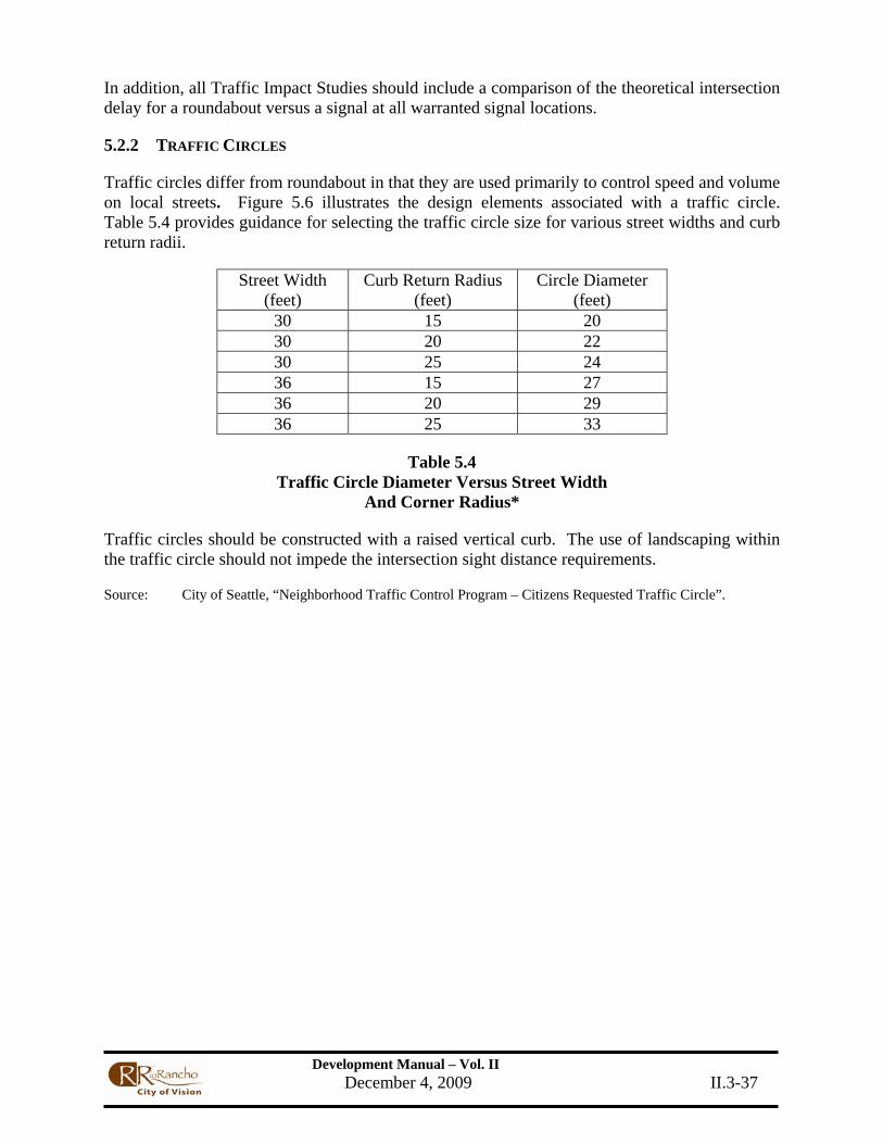
Development Manual – Vol. II December 4, 2009 II.3-37
In addition, all Traffic Impact Studies should include a comparison of the theoretical intersection delay for a roundabout versus a signal at all warranted signal locations.
5.2.2 TRAFFIC CIRCLES
Traffic circles differ from roundabout in that they are used primarily to control speed and volume on local streets. Figure 5.6 illustrates the design elements associated with a traffic circle. Table 5.4 provides guidance for selecting the traffic circle size for various street widths and curb return radii.
Street Width (feet)
Curb Return Radius (feet)
Circle Diameter (feet)
30 15 20 30 20 22 30 25 24 36 15 27 36 20 29 36 25 33
Table 5.4 Traffic Circle Diameter Versus Street Width
And Corner Radius*
Traffic circles should be constructed with a raised vertical curb. The use of landscaping within the traffic circle should not impede the intersection sight distance requirements.
Source: City of Seattle, “Neighborhood Traffic Control Program – Citizens Requested Traffic Circle”.

Development Manual – Vol. II December 4, 2009 II.3-38
Figure 5.6 Design Elements for Traffic Circles
Source: City of Seattle, “Neighborhood Traffic Control Program – Citizen Requested Traffic Circle (City Funded)” Policy No. 23, Seattle, WA, 1986.

Development Manual – Vol. II December 4, 2009 II.3-39
5.2.3 Applications Based on the local and collector street sections, the following types of roundabouts are applicable for use:
• Mini-roundabout • Urban compact roundabout • Urban single-lane roundabout • Rural single lane roundabout (rural roundabouts that may become part of an urbanized
area should be designed as a urban roundabout)

Development Manual – Vol. II December 4, 2009 II.3-40
6. Access to City of Rio Rancho Roadway System
6.1 ACCESS CONTROL
The efficiency and safety of a roadway depends largely on the number and character of interferences affecting vehicles moving along the facility. Major interferences are caused on most streets by vehicles entering, leaving, or crossing the road, at intersecting streets and driveways. In order to minimize accidents and to assure best overall use of the facility by the general public, it is necessary to regulate vehicle movements in and out of abutting developments and cross streets.
With respect to driveways, road users have certain rights of access to abutting property as well as the right to travel on the road with relative safety and freedom from interference. Since these various rights sometimes conflict, the City is given the responsibility for reconciling and satisfying, to the extent feasible, the needs and rights of all road users with respect to driveway location, design, and operation. When conflicts cannot be fully resolved, preference will be given to the safe and efficient use of the road, particularly when traffic growth requires additional storage capacity of left-turning vehicles at signalized intersections. In such cases, the City reserves the right to change a nearby access point from full access to partial to ensure safe, efficient operations of the adjacent signal.
Existing accesses, even if not in use, must not be relocated, altered, or reconstructed without approval from the City of Rio Rancho. When an access to a roadway with a curb and gutter is abandoned, it must be replaced by a full height curb across the abandoned access and the depression behind must be filled. When an access to a roadway with a shoulder and ditch is abandoned, it must be replaced by a matching existing shoulder and ditch.
6.1.1 ACCESS TO STATE HIGHWAYS
Access to State highways is regulated by the New Mexico Department of Transportation (NMDOT). The City of Rio Rancho will not review changes to an existing access or any new access which is in State right-of-way. Encroachment permits for access to State highways must be obtained directly from the NMDOT. The City shall review requests for new access where any portion of the access is in City right-of-way.
6.1.2 ACCESS TO CITY ROADWAYS
All construction to connect or change driveways entering City right-of-way must first be authorized by a valid City of Rio Rancho Curb Cut Permit and a Right of Way Use Permit. These permits can be obtained through the Department of Public Works at the following website: http://ci.rio-rancho.nm.us
The City currently follows the standards in the NMDOT State Access Management Manual (SAMM). No access points shall be approved without an acceptable project site plan indicating the location and number of access points. A Traffic Impact Study may be required to substantiate the need for access or any variances to the SAMM guidelines.

Development Manual – Vol. II December 4, 2009 II.3-41
6.2 DRIVEWAYS
6.2.1 DEFINITION
A driveway is any access constructed within the public right-of-way, connecting the public roadway with adjacent property and which does not cause the blocking of any sidewalk, border area, street, or roadway.
Some of the principles of intersection design apply directly to driveways. One important feature is the elimination of large graded or paved areas adjacent to the traveled way that allow drivers to enter or leave the street randomly.
6.2.2 DRIVEWAY TYPES
• A residential driveway is one providing access to a single family residence, a duplex, or an apartment building containing five or fewer dwelling units.
• A commercial driveway is one providing access to an office, retail, or institutional building, or to an apartment building having more than five dwelling units. Such buildings are customarily serviced by trucks as an incidental rather than a principal driveway use. Industrial plant driveways whose principal function is to serve administrative or employee parking lots are also considered commercial driveways.
• An industrial driveway is one directly serving substantial numbers of truck movements to and from loading docks of an industrial facility, warehouse, or truck terminal. A centralized retail development, such as a community or regional shopping center, may have one or more driveways specially designed, signed, and located to provide access for trucks. These are also classified as industrial driveways.
6.3 DRIVEWAY CHARACTERISTICS
6.3.1 SINGLE FAMILY RESIDENTIAL DEVELOPMENT
Driveways serving single family residential units should be designed in accordance with Standard Detail DW-01, "Sidewalk and Driveway Transitions (Residential)" and DW-02, “Sidewalk and Driveway Transitions (Collector)." If the driveway is to serve one single family unit, the maximum width should be 24 feet. For single family residential accesses, the width must equal the width of the garage opening if the garage is within 25 feet of the right-of-way line, up to a maximum of 30 feet. If one driveway is to serve two single family units, the maximum width should be 30 feet.
6.4 DRIVEWAY DESIGN
6.4.1 RESTRICTION OF TURNING MOVEMENTS
Where necessary for the safe and efficient movement of traffic, the City may require access points to be geometrically designed so as to provide for only limited turning movements. The restriction of turning movements should not affect the number and location of access points as specified elsewhere.

Development Manual – Vol. II December 4, 2009 II.3-42
6.4.2 ISLANDS FOR LIMITED MOVEMENT ACCESSES
The ends of the islands should typically be provided with 2-foot back of curb radii. Where site plans do not permit installation of islands in accesses as shown in Figures 6.1 through 6.3, the City Project Manager may permit or require the installation of a center median on the adjacent public street as an alternative.
Figures 6.4 through 6.7 are design guidelines for limited movement accesses. The design of these islands must accommodate a WB-50 design vehicle.
Acceleration and deceleration lanes may be required to be incorporated into the design. Islands must be provided with vertical curbs. Additional right-of-way or easement may be required to accommodate these designs
6.4.3 DESIGN
Generally, all new private property access will be designed as driveway cuts.
The design of accesses must also take into consideration the needs of truck traffic and must be checked using the appropriate turning template. Drainage patterns must also be taken into consideration in the design of accesses.
6.4.4 DRIVEWAY SIGHT DISTANCE
Adequate sight distance must be provided for vehicles exiting and entering a driveway. Driveway locations should be evaluated to determine whether a sight obstruction exists, such as buildings, signs, vegetation, parked vehicles, horizontal or vertical highway alignments, etc. The sight distance requirements for passenger cars are based on a 3.5 foot height of eye and 3.5 foot height of object. The distances for trucks are based on a 7.6 foot height of eye and 3.5 foot height of object.
If the sight distance is not adequate, consideration should be given to the following options:
• Removing the sight obstruction • Relocating the driveway to a more favorable location along the frontage • Prohibiting critical movements at the driveway • Relocating access to another street, a frontage road, or a joint access location
In all cases, stopping sight distance must be provided.
6.4.5 DRIVEWAY PROFILES
Adequate design of driveway grades should reflect consideration for basic functions of the adjacent street and the site that the access driveway serves. Generally, in order to enable safe ingress or egress maneuvers, driveway profiles should provide for sufficient clearance between the vehicle and the driveway surface.
Development Manual – Vol. II December 4, 2009 II.3-43
6.4.6 DRIVEWAY ANGLES
Two-way driveway should be as close to 90° to the roadway as possible (no less than 75°).
One-way driveway may be as flat as 75°. However, a minimum of an 85° angle is recommended for driveways in areas of high pedestrian or bicycle activity.
6.5.3 LARGE DEVELOPMENTS
For large developments, the City Traffic Engineer or Project manager may require the developer to consolidate access to a single point which may be signalized. Driveway signals must be located to provide satisfactory signal progression for through traffic on the public road.
6.6 DRIVEWAY LOCATIONS
6.6.1 DRIVEWAY SPACING
Refer to the NMDOT State Access Management Manual for guidance.
6.6.2 JOINT ACCESS
Joint access will be required for two adjacent developments where a proposed new access will not meet the spacing requirements set forth in this section. Joint access must be approved by the City Engineer.
6.6.3 DRIVEWAY CORNER CLEARANCE
Corner clearance for driveways on collectors and arterials are governed by the NMDOT SAMM. For residential street driveways, corner clearance is governed by City Code 96.02.
6.6.4 Driveway Location Restrictions
Driveway location on collectors and arterials are governed by the NMDOT SAMM. For residential street driveways, locations is governed by City Code 96.02.
6.6.5 DRIVEWAY LOCATION COORDINATION
It is necessary to coordinate the location of access for properties on opposite sides of the street so that they do not interfere with each other.
• Driveways should be located directly opposite each other to ensure that they share a single access location.
• Where lots are not large enough to allow accesses on opposite sides of the street to be aligned, the center of driveways not in alignment will normally be offset a minimum of 150 feet on all collector roads, and 330 feet on all industrial, major collector, and arterial roads. Greater distances may be required due to left turn storage lane requirements.

Development Manual – Vol. II December 4, 2009 II.3-44
6.6.6 VARIANCES
City of Rio Rancho Department of Public Works may grant variances from these driveway criteria.
6.7 DRIVEWAY STORAGE
The design of a driveway should take into consideration the space necessary to store vehicles using the driveway. This applies to both vehicles making a left turn from the roadway and to vehicles stopped on the driveway waiting to enter the roadway. Adequate storage area is necessary to provide safe and efficient movement of vehicles and pedestrians on the public right-of-way.
The recommended vehicle storage area needed for the entire site may be spread over several accesses if more than one access serves the site. The recommended distance may be further adjusted by the City for accesses with two approach lanes and will be subject to traffic volumes and site layout.
When a development is located adjacent to a public road, the parking facility must have full internal vehicular circulation and storage. Vehicular circulation must be located completely within the property and vehicles within one portion of the development must have access to all other portions without using the adjacent road system.
6.8 ACCELERATION AND DECELERATION LANES
Refer to NMDOT State Access Management Manual for guidance.

Development Manual – Vol. II December 4, 2009 II.3-45
7. Bicycle Facilities Guidelines
7.1. BASIC CRITERIA
7.1.1 GENERAL
The City of Rio Rancho bicycle policy is follows the Guide for the Development of Bicycle Facilities, The American Association of State Highway and Transportation Officials, ("AASHTO").
The guidelines presented in this section primarily address the development of on-street bicycle facilities. All new roadways which are legal for bicycle use should be designed and constructed under the assumption that they will be used by bicyclists. Bicycle lanes will be included as part of the standard cross section on all arterial and collector streets when they are designed, constructed, reconstructed, or widened.
Regarding bikeway facilities, all new developments and new roadway construction must meet City standards.
7.1.2 DEVELOPMENT OF PLANS AND SPECIFICATIONS
Except where these standards provide otherwise, testing, report preparation, design, design details, workmanship, and materials shall be in accordance with the current editions of the following publications:
(1) Guide for the Development of Bicycle Facilities, The American Association of State Highway and Transportation Officials, ("AASHTO").
(2) Manual On Uniform Traffic Control Devices (MUTCD), U.S. Department of Transportation.
(3) ADA Standards for Accessible Design Guidelines, U.S. Department of Justice
7.1.3 VARIANCES
Variances from these standards and procedures may be granted by the City Engineer upon evidence that such variances are in the public interest, that they are based upon sound engineering judgment, and that safety, function, appearance, and maintainability requirements are fully met. Variances must be requested and approved in writing.
7.2 DEFINITION OF TERMS
Definitions of bicycle facilities and general design guidelines are listed in the following sections. Refer to the AASHTO 1999 Guide for the Development of Bicycle Facilities for detailed design criteria.
(1) SHARED USE PATH/TRAIL (BIKE TRAIL) – A shared use path is a bikeway physically separated from motorized vehicle traffic by an open space or barrier, and constructed within the street right-of-way or within an independent right-of-way including shared-use rights-of-way or utility or drainage easements.

Development Manual – Vol. II December 4, 2009 II.3-46
Trails should be expected to accommodate other uses including walking, jogging, and rollerblading and should be designed to recommended standards for these uses. The recommended width for a trail is 10 feet, with 12 feet or more recommended in high use areas (See Figure 7.1). High use areas are those trails identified on the Long-Range Bikeway System.
Trail design considerations include: signing; striping; markings; horizontal, vertical and intersection sight distance; surfacing; and trailside clear zones.
Where trails intersect with the street network, safe connections to the on-street bikeway system should be designed. Raised or protected median refuge areas should be considered for bicyclists at mid-block crossings of arterial roadways.
Traffic signal warrant analyses, per the Manual on Uniform Traffic Control Devices (MUTCD), and other studies may be conducted for bike trail crossings of major roadways which have been identified as high-priority bicycle and pedestrian crossings. See the references in Section N.5.a., b., and e. for evaluation considerations.
Figure 7.1 Multi-Use Trail Typical Cross Section
Development Manual – Vol. II December 4, 2009 II.3-47
(2) BICYCLE LANE (BIKE LANE) - A bike lane is a lane on the roadway that has been designated by striping, signing, and pavement markings for preferential or exclusive use by bicyclists. Bike lanes or paved shoulders are part of the standard arterial and collector cross-section. These lanes provide access to destinations that include parks, schools, shopping and employment centers. Bike lanes at signalized intersections should have bicycle-sensitive actuation capability such as loop detectors, video detection, curbside push buttons, or other detection devices approved by the City Traffic Engineer. Adequate sight distance shall be maintained at all intersections and driveways along a bike lane.
(a) Development of Bike Lanes on New or Reconstructed Roadways
Bike lanes should be provided on all new or reconstructed arterial and collector roadways. Recommended minimum widths for bicycle lanes are as follows:
• 5 feet, measured from painted edgeline to edge of gutter, on roadways with posted speed limits of 40 mph or greater.
• 4 feet, measured from painted edgeline to edge of gutter, on roadways with posted speed limits of 35 mph or less.
Bike lanes shall be flush with roadside gutters and should be marked in accordance with the MUTCD and AASHTO guidelines and City of Rio Rancho Standards. (Divided roadway with bike lanes, Four-lane roadway with bike lanes, Two-lane collector street with bike lanes)
Future roadway improvements should retain existing bike lanes, including intersection approaches where additional turn-lanes may be constructed. Bike lane intersection design guidelines are provided in Sections N.4.a. of this chapter.
(b) Development of Bike Lanes on Existing Roadways
The addition of bike lanes as part of arterial and collector rehabilitation is recommended where feasible. Bike lanes may be implemented on existing roadways by reducing travel lane and median widths within acceptable City guidelines, as part of restriping, resurfacing, or rehabilitation projects. Narrower bike lanes may be considered where the inclusion of bike lanes in desirable, but standard widths are not feasible.
(c) Development of Bike Lanes with On-Street Parking
Bike lanes may be developed along arterial and collector roadways with or without on-street parking. Where on-street parking is present, bike lanes should always be located to the left of the parking lane and should have a minimum width of 5 feet. Bike lanes are travel lanes, therefore, automobile parking or motor vehicle use of a bike lane as a driving or passing lane should be prohibited. Parking demand should be evaluated to determine whether parking can be eliminated to reduce vehicle-bicycle conflicts or to convert the parking lane to a bike lane.

Development Manual – Vol. II December 4, 2009 II.3-48
(3) PAVED SHOULDER BIKEWAYS – Paved shoulder bikeways are located on uncurbed arterials and collectors and consist of a smooth paved surface that covers all or part of the roadway shoulder. Recommended widths for paved shoulder bikeways are as follows:
• 6 feet, measured from painted edgeline to edge of pavement, on roadways with posted speed limits of 40 mph or greater.
• 5 feet, measured from painted edgeline to edge of pavement, on roadways with posted speed limits of 35 mph or below.
In addition, on low-speed, low-volume local streets, a 4-foot width may be considered where right-of-way constraints exist.
Paved shoulder bikeways may be implemented on existing roadways through use of measures similar to those described in Section N.1.a.(2.)(b). Intersection sight distance should be verified at all intersections and driveways along a paved shoulder bikeway.
(4) BICYCLE ROUTE (BIKE ROUTE) - Bike routes are designated roadways with appropriate directional and informational signing, with or without a specific bicycle route number, in accordance with the MUTCD. Bicycle routes shall be primarily located on local streets and low-volume, low-speed collector streets.
Bicycle routes on local streets should have 28-foot wide pavement widths. A collector roadway should have a minimum curb lane width of 14 feet, exclusive of parking, and can be implemented with minor or no additional provisions.
(5) WIDE CURB LANES - Wide curb lanes are located on shared roadways with outside lane widths of 14 to 16 feet. Lane widths greater than 16 feet may encourage operation of two motor vehicles in one lane, therefore, consideration should be given to striping a bicycle lane.
Wide curb lanes are recommended as part of rehabilitation and reconstruction projects on existing roadways where implementation of bicycle lanes or paved shoulder bikeways are infeasible. To implement wide curb lanes on existing roadways, travel lane widths and median widths may be reduced per City design guidelines and/or the curb and gutter may be reconstructed.
(6) SHARED ROADWAY - A shared roadway is any roadway that may be legally used by both motor vehicles and bicycles and is not specifically designated as a bikeway.
(7) BIKEWAY - A bikeway is any road, path, or way that is specifically designated for bicycle travel.
(8) BICYCLE FACILITIES - Bicycle facilities are the infrastructure that accommodates or encourages bicycling including bikeways, shared roadways not specifically designated for bicycle use, bicycle parking and storage facilities, and bicycle signal actuation hardware.

Development Manual – Vol. II December 4, 2009 II.3-49
7.3 THE BIKEWAY SYSTEM
The bikeway system is intended to safely connect residential areas, employment, retail services, businesses, education centers, and recreational facilities. The bikeway System is also intended to include recreational bikeways.
7.3.1. OTHER ELEMENTS
Other elements of the bikeway system include the following:
(1) provide safe bicycle facilities; (2) provide a system of bikeways interconnecting the four quadrants of the City and
surrounding communities; (3) establish primary bikeways along routes with substantial bicycle commute
volume; (4) provide a variety of bikeways which meet or exceed AASHTO or other approved
State/Local guidelines; (5) provide extensions and connections to the existing network; (6) include provisions for bicycle transportation, commuting, and recreational travel
associated with future development of arroyos, irrigation ditches, and drains; (7) provide for bicycle access to the bikeway system as expansion or modification of
the metropolitan street system occurs; (8) provide for the safe crossing of bicycling barriers such as freeways, railroads,
arroyos, acequias and the Rio Grande; (9) preserve and enhance existing bikeways on streets that change their traffic
carrying function or are reconstructed; (10) achieve approximately one-half mile intervals between bikeways; and, (11) encourage frequent bicycle access between new developments and adjacent
bikeways and to identify that access on the sketch plat, preliminary plat and/or site development plan as appropriate.
7.3.2 OFF-STREET BICYCLE FACILITIES
a. Generally, Bike Trails should be located to serve corridors not served by streets and highways or where wide rights-of-way exist, permitting such facilities to be constructed away from the influence of parallel streets.
b. Bike Trails should provide either a recreational opportunity or serve as direct high-speed commute routes, if cross-flow by motor vehicles can be minimized.
c. In locating a Bike Trail, consideration should be given to the provision of adequate access points.
d. The scenic value is particularly important along a Bike Trail intended to serve a recreational purpose.
e. Recommended rights-of-way are:
(l) the arroyo (drainage) system through the City; (2) abandoned railroad rights-of-way; (3) utility easements and rights-of-way; and (4) paths through parklands. (5) along roadways with sufficient R/W and appropriate design features.

Development Manual – Vol. II December 4, 2009 II.3-50
7.3.3 ON-STREET BICYCLE FACILITIES
a. Purpose
(1) On-street bikeways are designated as bike routes or bike lanes and are designed for transportation mobility.
(a) On-street bikeways emphasize functional service qualities such as the fastest, most direct, and unencumbered access to destinations.
b. General Bikeway Location Criteria
(1) Major on-street bikeways are located primarily along roadways classified as arterial or collector to provide access to destinations.
(2) Minor on-street bikeways, such as bike routes, are located on local streets and low-volume collectors to provide access between residential areas and major bikeways.
(3) It is desirable for bikeways to be located on roadways where on-street parking is infrequent, prohibited, or can be prohibited.
(4) High-speed traffic (posted speed of 40 mph or greater) and the presence of large vehicles (truck, bus, or recreational vehicle) are significant factors affecting the acceptability of potential bikeway locations. In locations where these conditions exist, bike lane widths of 5-feet or greater are recommended.
(5) An on-street bikeway should be located only where the pavement will be smooth and properly maintained. Dense graded asphalt concrete surfaces are preferable to open graded or seal-coated surfaces.
(a) Manhole and utility covers should not be located in bikeways, and where relocation is impractical, these features should be adjusted to grade.
(b) Drop inlet or other drainage grates should be designed to prevent the snagging of bicycle wheels.
(c) Construction joints or large transverse pavement surface cracks (greater than 1 inch in width) in on-street bikeways should be repaired.
(d) Pavement edges, including where the asphalt concrete roadway meets the Portland cement concrete gutter, should be flush to enhance bikeway safety. Gutters may be reduced (e.g., 1-foot), where drainage conditions permit, on new or reconstructed roadways to provide greater curb lane width for bicycling.
(6) In new residential or commercial developments adjacent to bikeways, contiguous walls or fences should provide breaks for paved bicycle access which link the development to the bikeway system. Access(es) should be delineated on the sketch plat, preliminary plat, and/or site development plan as appropriate.
(7) Potential on-street bikeway locations should include no more than one stop sign or traffic signal per 1/4 mile. Local street stop control should be
Development Manual – Vol. II December 4, 2009 II.3-51
reassigned to facilitate through bicycle traffic on designated bikeways. Stop control reassignment requires an engineering study to determine additional measures necessary to minimize neighborhood impacts. Concurrently, traffic calming strategies for through motorized traffic should be analyzed.
c. Location Considerations for Bike Lanes
(1) Bike lanes should be located along arterial and collector roadways. Bike lane widths are a function of the posted speed limit and automobile volumes.
(2) Where automobile parking lanes are included within the roadway, the parking lanes and bike lanes should be delineated separately to prevent use of bike lanes by motor vehicles. Parking demand should be evaluated to determine whether parking can be eliminated or the parking lane can be converted into a bike lane. Bike lanes are traffic lanes, therefore, automobile parking or motor vehicle use of a bike lane as a driving or passing lane shall be prohibited.
d. Location Considerations for Bike Routes
(1) Bicycle routes are primarily on low-volume, low-speed collectors and local streets. If adequate space is provided for a vehicle to safely pass a bicyclist, a bike route may be signed on an arterial.
(2) It may be necessary to sign a bike route for a short distance along an arterial with minimal 4-foot bicycle lanes, 5-foot paved shoulders, or a 10-foot multi-use sidewalk trail where local streets are not feasible to continue the bikeway. (See Section 4.c.(2) for additional information on design of sidewalks as multi-use trails.)
7.3.3.4 SPECIAL PROVISIONS FOR BIKEWAY FACILITIES
a. Proposed facilities require a safety assessment of potential motor vehicle-bicycle conflicts. These conflicts are considered in four categories.
(1) Parallel Conflicts: Speed differential between automobiles and bicycles and the average daily volume of motor vehicle traffic reduce bikeway safety. Lower speed and lower volume roadways should produce fewer conflicts, resulting in safer bicycle travel.
(2) Right Turn Conflicts: (a) Dual Right-Turn Lanes
Dual right-turn lanes on bikeways present safety concerns for cyclists traveling straight through an intersection. Warrants for dual right-turn lanes should be used to ensure that they are provided only where warranted. Intersections with dual right-turn lanes should be constructed in accordance with guidelines that minimize bicycle-automobile conflicts. All designs must be

Development Manual – Vol. II December 4, 2009 II.3-52
approved by the City Traffic Engineer.
(b) Free Right-Turn Lanes
Free right-turn lanes at intersections are not advised due to potential adverse impacts to bicyclist and pedestrian safety. Free right turns permit higher motor vehicle speeds approaching and through the right-turn movement. Where free right-turns are warranted, signing, marking, and geometric enhancements designed to warn motorists of pedestrian and bicycle traffic and to slow motor vehicles on approaches should be considered. These enhancements may include over-sized signing and marking, and reduced lane and turning radii widths for right-turning vehicles.
(c) Separate Right-Turn Lanes
Separate right-turn lanes should only be constructed where warranted by an engineering study. These lanes must be clearly signed and marked in accordance with the MUTCD. These lanes create bicycle-automobile conflicts because right-turning vehicles must cross the bikeway.
Where right-turn lanes are warranted, bicycle lanes and bicycle signal actuation systems should be provided at intersection approaches. Minimum curb return radii should be utilized to reduce motor vehicle speeds and reduce pedestrian crossing distances at intersections. (
(d) Access Controlled Facility Right-Turn Access
Oversized signing and marking is recommended for bike lanes and bike routes at access ramps to access controlled roadways.
(3) Left Turn Conflicts: Where left turn phases are warranted at signalized intersections along a designated bikeway, left turn bicycle actuation via bicycle detection or median push button should be provided.
(4) Crossing Conflicts: Signalized intersections are a positive means of crossing a roadway. MUTCD pedestrian signal warrant analyses should be performed for unsignalized arterial crossings which serve as barriers within the continuous bikeway system. Raised median refuge islands that allow bicycle passage should be considered to improve the safety of unsignalized arterial crossings.
b. Bikeway Grades Guidance for grade acceptability is a function of the slope and length of roadway grade. Bikeways with grades equal to or exceeding 5.0 % for more than 500 feet

Development Manual – Vol. II December 4, 2009 II.3-53
are less desirable because the ascents may be difficult for bicyclists and the descents may cause bicyclists to exceed a comfortable speed. Table 7.1, below, summarizes the acceptability and design concerns for the bikeway types.
Bikeway Type Distance (Ft.) Distance (Ft.) Design Concerns
Bike Trail < 500 Good 30 mph design speed/12 foot width
Bike Trail > 500 Poor 30 mph design speed/12 foot width
Bike Lane < 500 Good 4 to 5 foot width (stripe to edge of gutter)
Bike Lane > 500 Good 5 to 6 foot width (stripe to edge of gutter)
Bike Route < 500 Good Good sight distance, advance warning of traffic control
Bike Route > 500 Poor Consider alternate location or provide good sight distance,
advance warning of traffic control
Table 7.1 Bikeway Grades Greater than 5.0%
c. The crossing of physical barriers is an important factor in providing bikeway continuity and increasing bike usage. Two primary barriers are the Rio Grande and access controlled highways. Railroad tracks, arterial crossings, and large tracts of land not allowing through access are also barriers. Three solutions to provide safe crossing of major transportation barriers include the following:
(1) A bike lane may be created on an existing arterial through restriping, reducing vehicle travel lane or median widths.
(2) The sidewalk may be designated as a legal trail for short distances of up to one-quarter mile to serve as a linkage within the bikeway network. Two-way bicycle traffic as well as pedestrian traffic should be expected on sidewalks under these conditions. Sidewalk trails should be designed per Section N.1.a.(1) and this section to safely accommodate both pedestrian and bicycle traffic.
Driveways and cross-streets should be limited to 4 or less per quarter-mile before sidewalk trails are implemented. If the distance between the sidewalk trail and roadway is less than 5 feet, a physical divider should be considered.
Development Manual – Vol. II December 4, 2009 II.3-54
Sidewalk bikeways or trails immediately adjacent to the roadway are not recommended. This is due to several factors including wrong-way travel by bicyclists, conflicts at intersections and driveways, insufficient sight distance due to walls and other obstructions, and conflicts within the right-of-way such as utility poles.
(3) All new or reconstructed roadway over-passes should include wide curb lanes, multi-use emergency breakdown lanes, or bike lanes to improve bicyclist and motorist safety. Cantilevered structures attached to existing bridges should be considered where widening is not cost effective.
d. Construction within Right-of-Way
If construction or utility work is necessary within a bike lane, the full width of the bike lane should be repaved to grade after work is complete. Safe detour provisions for bicyclists should be made when bike lanes are temporarily closed for utility work.
7.3.3.5 BICYCLE PLANNING AND DESIGN GUIDELINE REFERENCES
Guide for the Development of Bicycle Facilities. American Association of State Highway and Transportation Officials, 1999.
Manual on Uniform Traffic Control Devices. Federal Highway Administration, 1988 (including current adopted amendments).
Selecting Roadway Design Treatments to Accommodate Bicycles. Federal Highway Administration, 1994.
New Mexico Bicycle-Pedestrian-Equestrian Transportation Plan. Bicycle/Pedestrian/ Equestrian Advisory Committee, New Mexico State Highway and Transportation Department, 1996.
Trails and Bikeways Facility Plan. City of Rio Rancho, 1996 (Revised).
Pedestrian and Bicyclist Safety and Accommodation. National Highway Institute, Federal Highway Administration, 1996.
Oregon Bicycle and Pedestrian Plan. Oregon Department of Transportation, 1995.
7.3.3.6 Addendum: Advantages of Bicycle Lanes/Paved Shoulders
1. Improved space is provided for bicycle use and in limited cases for pedestrian use; safety is improved for motorists who will not have to travel out of the lane in order to pass bicyclists.
2. Improved space is provided for motor vehicles to stop out of the travel lane because of mechanical difficulty, a flat tire, or other emergency.
3. Improved space is provided to escape potential accidents or reduce their severity. 4. Improved space is provided for emergency vehicle access through congested areas as

Development Manual – Vol. II December 4, 2009 II.3-55
motorists pull to the curb to allow emergency vehicles to pass. 5. The sense of openness created by bike lanes/paved shoulders improves the safety and
drivability of the roadway. 6. Sight distance is improved both for users traveling along the roadway with bike
lanes/paved shoulders as well as for users entering the roadway from a side street or driveway.
7. Highway capacity is improved; uniform speed is encouraged. 8. Improved space is provided for maintenance work such as snow removal and
maintenance of utilities. 9. Improved space is provided for motorists who have accidentally left the travel lane to
recover and return to the lane. 10. Improved space is provided to discharge storm water from the travel lanes, increasing
safety for users and capacity of the roadway. 11. Pavement life is increased because structural support is given to the pavement, reducing
the raveling effect caused by motor vehicles traveling on the edge of pavement or traveling immediately adjacent to the gutter pan.
12. Improved space is provided for bus stops. 13. Increased safety is provided for right-turning vehicles due to increased turning radii at
intersections and driveways; rear-end accident potential is reduced. 14. Increased safety is provided for motorists to avoid fixed objects such as telephone and
signal poles due to provision of additional clear zone area. 15. Improved space is provided by paved shoulders for motorists to pass on the right of left-
turning vehicles, where allowed by law. 16. Air quality benefits are provided due to provision of space for alternative modes of travel
and to reduced particulate matter caused by vehicles traveling on unpaved shoulders.
a. Classes of bikeways may be defined as follows:
(1) Class I Bikeway: A Bike Trail located in a completely separated right-of-way designated by signs and pavement markings for the exclusive use of bicycles with cross flows by the motor vehicles minimized. The right-of-way for these bikeways could accommodate other uses such as hiking and jogging if properly designed.
(2) Class II Bikeway: A Bike Lane that is located in a portion of the roadway designated by signs and pavement markings for the exclusive or semi-exclusive use of bicycles with through travel by motor vehicles or pedestrians prohibited, but with vehicle parking and cross flows by pedestrians and motorists permitted.
(3) Class III Bikeway: A Bike Route located in a roadway and designated by signs and shared with pedestrians or motorists. The bike route provides continuity to other bicycle facilities.
b. The Bikeway Network is intended to safely connect residential areas, employment, retail services, businesses education centers and recreational facilities. It is also intended to include recreational bikeways. Other elements of the Bikeway Network concept include the following:

Development Manual – Vol. II December 4, 2009 II.3-56
(1) safety; (2) provide a system of bikeways interconnecting the four quadrants of the
City and surrounding areas; (3) establish primary bikeways along patterns of heavy bicycle commuting; (4) provide a variety of bikeways for study and experimentation; (5) provide extensions and connections to the existing network; (6) include provisions for bicycle transportation and recreation associated
with further development of arroyos, irrigation ditches, and drains; (7) provide for bicycle access to the Bikeway Network along with further
expansion or modification of the metropolitan street system; (8) provide for the safe crossing of bicycling barriers, such as freeways,
railroads and the river; (9) provide for relocation of Bikeways if necessary where any street changes
significantly in its traffic carrying function; and (10) achieve approximately one-mile intervals between bike facilities.
c. The Bikeways Master Plan is a graphic representation of an updated version of the Bicycle Network established in 2001. The Master Plan identifies the locations, alignments, connections and type of bicycle facilities for the Rio Rancho Urban Area. The status of program priorities for bicycle facility development is identified in the following categories:
(1) Existing bicycle facilities that are currently in operation. (2) Planned bicycle facilities that either are included in the Transportation
Improvement Program for the Rio Rancho Urban Area or are expected to be developed along with associate roadways, drainageways or as funds become available.
(3) Study corridors where bicycle facility type and alignment have not been established but are under consideration.
(4) Existing or planned major grade separated overcrossings.
2. Off-Street Bicycle Facilities
a. Generally, Bike Trails should be located to serve corridors not served by streets and highways or where wide rights-of-way exist, permitting such facilities to be constructed away from the influence of parallel streets.
b. Bike Trails should provide either a recreational opportunity or serve as direct high-speed commute routes, if cross-flow by motor vehicles can be minimized.
c. In locating a Bike Trail, consideration should be given to the provision of adequate access points.
d. The scenic value is particularly important along a Bike Trail intended to serve a recreational purpose.
e. Recommended rights-of-way are:
(1) the arroyo (drainage) system in the City; (2) abandoned railroad rights-of-way; (3) utility easements and rights-of-way; and (4) paths through parklands.

Development Manual – Vol. II December 4, 2009 II.3-57
(5) along roadways with sufficient R/W and appropriate design features.
3. On-Street Bicycle Facilities
a. General Locational Criteria are as follows:
(1) The on-street bikeways are designated as Bike Routes or Bike Lanes and are primarily designed for transportation purposes.
(2) These types of bicycle facilities generally emphasize functional service qualities such as the quickest, most direct, and unencumbered access to most destinations.
(3) It is desirable to select a location where on-street parking is light or where it can be prohibited.
(4) High-speed traffic and/or truck, bus, and recreational vehicle traffic are significant factors affecting the acceptability of potential bikeway locations. In locations where these vehicles and bicycles must share a right-of-way, extra separation must be available between cyclists and vehicles.
(5) An on-street bikeway should be located only where pavement can be maintained at a reasonable standard. Dense graded asphalt concrete surfaces are preferable to open graded or seal-coated surfaces. All manhole covers, utility covers, drop inlet grates, and construction joints or cracks in the surface should be at grade or brought to grade and safety standards before establishing a bikeway.
(6) For an on-street bikeway, the speed and volume of auto traffic is a factor, along with the available width, in determining the best location. Areas where mixed flows may be acceptable are:
(a) In urban centers where traffic conditions constrain motor vehicle speeds to be less than 40 mph resulting in considerable overlap of bicyclist and motor vehicle speed distributions;
(b) Within the approaches to intersections where motor vehicle speed is depressed preparatory to stops, turning movements and intersection related decisions;
(c) On streets with less than 14,000 average daily traffic volumes.
(7) Potential on-street bikeway locations should include no more than one stop sign or traffic signal per 1/4 to 1/2 mile intervals. Stop signs should be rearranged to the extent possible to permit through bicycle traffic. At the same time, deterrents to motorized through-traffic should be implemented.
b. Locational considerations for Bike Lanes include the following:
(1) Adequate pavement width must be available for both bicycles and motor vehicles. (2) A location should be able to provide a minimum of four feet of operating width
for one-way bicycle travel, exclusive of the gutter width. (3) Bike Lanes should be placed on all collector and arterial streets. (4) At locations where on-street parking is allowed to remain, the adjacent Bike Lane
should be wide enough to permit a bicyclist to pass a parked car. (5) Bike Lanes, if necessary, may be placed on arterials where the center divider can
be reconstructed and the traffic lanes moved in toward the center. (6) Bike lanes may be placed on Principal Arterials on shoulder areas when
Development Manual – Vol. II December 4, 2009 II.3-58
appropriately designed.
c. Locational considerations for Bike Routes include the following:
(1) Local streets in the Bikeway Network should be designated as Bike Routes. (2) Bike Routes may be placed where bicycle traffic is already heavy and where other
bicycle facilities are not feasible. (3) Arterials should be avoided if at all possible; however, it may be necessary to use
arterials when other bicycle facilities are not feasible.
4. Special Provisions for Bikeways
a. Each proposed and existing facility should be evaluated on a safety basis of potential motor vehicle-bicycle conflicts, as categorized into four categories:
(1) Parallel Conflicts: Close proximity of auto and bike travel, speed differential between the two, and the average daily volume of motor vehicle traffic.
(2) Right Turn Conflicts: An unchannelized intersection presents relatively minor problems for cyclists; a double right-turn lane presents unacceptable hazards.
(3) Left Turn Conflicts: Intersections with left-turn phase signalization present no hazards and should be highly rated. Signalized intersections, without separate phasing should be on the basis of turning volume and opposing traffic, as should major unsignalized intersections and driveways on major streets.
(4) Crossing Conflicts: Signalized intersections are the most positive means of dealing with crossing traffic and should therefore be highly rated for safety. Any location which controls cross traffic by STOP or YIELD signs is also relatively safe.
b. Grade acceptability is judged in terms of the slope and length of the grade. A general standard to apply is that a grade of 10 percent would be tolerable for a distance of 50 feet or less. Also, grades of five percent, for a length of 150 feet and longer, should be avoided.
c. The breaching of barriers may be one of the most important factors in providing continuity and increasing bike usage. The two most obvious physical barriers locally are the Rio Grande and the principal arterials. Three possibilities for safe bicycling crossings are recommended:
(1) A Bike Lane may be marked on the roadway. This criterion would not apply in those instances where insufficient roadway would result in decreasing the number of required motorized vehicle lanes.
(2) Even in its safest form, a Bike Lane on a highway bridge forces the cyclist onto a busy street. A far better solution is to have a completely separate bridge for non-motorized traffic.

Development Manual – Vol. II December 4, 2009 II.3-59
8. Landscaping
8.1. LANDSCAPE DESIGN STANDARDS
8.1.1 PURPOSE
These Landscape Design Standards have been written to serve as a guide to landscape architects and engineers for purpose of designing and reviewing roadway landscape plans.
8.1.2 DESIGN CRITERIA
The surroundings in which the roadway is being designed will have a strong influence on the landscape design. The design shall be respectful of existing natural features such as landforms and vegetation. When the roadway traverses urban developed areas, the landscape design shall reinforce the adjacent landscape theme or character. The principles of low maintenance and low water use shall be incorporated into all landscape designs.
Under any circumstances the design shall not compromise on safety of all roadway users, including motorists, pedestrians, bicyclists, and construction and maintenance workers.
8.1.3 PROCESS
Many elements need to be considered during development of the landscape design. The landscape design process shall begin with a thorough inventory and analysis of existing conditions, including: the natural landscape elements, topographic and physical characteristics, ecological factors, recreational potentials, residential qualities, historical features and visual values. The results of the inventory/analysis shall be incorporated into a schematic or concept design submittal (typically included in the 30% submittal).
Subsequent steps in the design process will be determined by the size and complexity of the project. Relatively simple projects may require only schematic levels of design prior to preparation of construction documents. Typically, an intermediate design development stage - the preliminary design - is required between the conceptual design development and construction document preparation. On larger projects, additional design and/or planning activities (i.e., visual studies, native plant surveys, land use evaluations, etc.) may be necessary.
Early in the project development stage, the landscape architect shall consult with the City of Rio Rancho Design Guidelines when published for guidance on the landscape design submittal requirements, including sheet size, order of drawings, standard notes and details, special provisions, etc.
8.2 DESIGN CONSIDERATIONS
8.2.1 ALIGNMENT AND PROFILE–SIGHT DISTANCES AND SIGHT LINES/TRIANGLES

Development Manual – Vol. II December 4, 2009 II.3-60
8.2.1.1 Sight Triangles
When designing landscaping around intersections, driveways, or other approaches onto a street, plant material placement and height restrictions must be observed. The purpose of these restrictions is to maintain visibility for the driver to turn safely at intersections. Major intersections are considered primary; un-signalized intersections are secondary, and side streets and driveways are tertiary.
Sightline shall be maintained for all intersections. The roadway classification for the road being designed will be designated by the City Traffic Manager. General standards regarding the design speed for various classifications of roads are presented in Tables 4.2 and 4.3. Sight distance is a function of design speed. Once the design speed is established, refer to the equation and/or figures discussed in the intersection sight distance section of SECTION 5 to determine the required sight distances. The required sight distances are then applied in Figure 8.1. The sight distance lines shall be shown, dimensioned and labeled on the landscape plans.
An open view must be maintained between 2-feet to 7-feet above grade for proper visibility within the sightline triangle (refer to Figure 8.1). Plants cannot be planted within the sight triangle if they have a potential to reach a mature height greater than 2-feet above the roadway pavement. Trees must have a canopy that can be maintained 7-feet above the roadway pavement without extensive pruning. See: “Height Restrictions and Pruning Requirements Within The Sightline Triangle,” Figure 8.2. The designer shall evaluate the plant choice for compliance with the sight line criteria. Plants may be considered by the City for use on a project-by-project basis.
Vegetation shall not block sight lines to signs.

Development Manual – Vol. II December 4, 2009 II.3-61
Figure 8.1 Intersection Sight Distance
Development Manual – Vol. II December 4, 2009 II.3-62
8.2.2 ROADSIDE DEVELOPMENT
8.2.2.1 Offset Distances For Trees
Trees, large shrubs and cacti whose trunk diameter at maturity will exceed 4 inches shall not be planted within the clear zone. The diameter measurement shall be taken at 12 inches above grade. Refer to SECTION 4.0, SUBSECTION 9.0 CLEAR ZONES for information on clear zone width. The clear zone width is not to be considered a fixed single control dimension. Variations in cross section design and traffic speed may increase or decrease this distance. Shrubs and ground covers may be planted or retained within the clear zone for safety and aesthetic purposes as approved by the City of Rio Rancho. Existing trees may be retained under the following circumstances:
• If they are on the high or cut side of the roadway beyond the clear zone distance or, • If they are on the low or fill side, if protected by a guardrail or beyond the clear zone
distance.
For 50 MPH or greater design speed, minimum clearances for newly planted trees, shrubs and cacti with an ultimate trunk diameter of more than 4 inches shall be 30 feet unless one of the following reasons will allow for a lesser distance:
• Where cut slopes are 3:1 or steeper; 10 feet behind the point of vertical intersection (PVI) at the toe of the slope.
• Where concrete barriers, walls, abutments, or other rigid obstructions are used, 4 feet behind the obstruction.
• Where a flexible guardrail is used (w-beam), 4 feet behind the rail. • Where there are barrier curbs near a traveled lane, 10 feet behind the face of the curb.
(Except Medians). • Where limited right-of-way or the necessity for planting would result in less clearance;
all factors in the particular problem area shall be weighed to decide if a special exception is warranted.
• The offset where there is bicycle traffic shall be a minimum of 7 feet from the edge of the bicycle facility, and have a minimum 10 feet of clearance to the canopy.
For design speed less than 50 MPH, minimum clearances for newly planted trees, shrubs and cacti with an ultimate trunk diameter of more than 4 inches shall meet the clear zone requirements of Figure 4.10 unless one of the reasons listed above will allow for a lesser distance.
On curves, adequate sight distance for the design speed of the roadway must be maintained.
Modification of the minimum clearance may be required by special considerations. For example, occasionally, special conditions may warrant planting closer to the pavement in order to fulfill a specified function or requirement. Plantings in the reduced clear zone shall consist of low-growing shrubs and groundcovers under 2 feet in height. Also, the characteristics of the plant material proposed for use will affect the amount of offset required.
Development Manual – Vol. II December 4, 2009 II.3-63
8.2.3 UTILITIES AND EQUIPMENT
No landscaping shall be installed within 10 feet of fire department equipment (i.e. fire hydrants, Dire Department Connections (FDC), and gate valves (PIV).
No landscaping shall be planted within 10 feet of water and sewer main lines.
8.2.4 LANDSCAPE MEDIANS
Apart from improving roadway aesthetic median landscaping also provides means to mitigate headlight glare, and reduces potential for driver monotony. A landscaped median can also serve to reduce the perceived scale of the roadway.
The minimum clearance for trees in the median is six feet behind the face of a curb, provided that the location meets the sight line criteria. Trees, shrubs or cacti that will exceed 4 inches in diameter at maturity shall not be planted in median without curb.
Mature tree growth shall be maintained 2-feet behind the face of the curb line. See Figure 8.2.
8.2.5 GRADING, DRAINAGE, AND IRRIGATION
8.2.5.1 Grading
The proper shaping of slopes can benefit drainage, erosion control, aesthetic, and future maintenance. Grading plans shall be used wherever feasible. The grading shall always be smooth enough to meet safety requirements, permit easy maintenance, and adequately serve the needs of surface drainage. Grading shall integrate the hydrology, aesthetic and earthwork needs for the site and maximize use of storm water runoff to support the landscape development.
8.2.5.2 Erosion Control
In planting design, the following parameters shall be considered to control erosion:
• Slopes with ratios of 3(h):1(v) and flatter favor the establishment of natural vegetation as protection against erosion. Slopes with ratios of 4(h):1(v) and flatter add to vehicular safety.
• Plant along the contour of the slope. Avoid planting arrangements that would encourage erosion.
• Stabilize soils at dip sections in both the right-of-way and the median where applicable. The use of decomposed granite in dip sections is prohibited.

Development Manual – Vol. II December 4, 2009 II.3-64
Figure 8.2 Height Restrictions and Pruning Requirements Within The Sightline Triangle
8.2.5.3 Underground Irrigation
Irrigation systems are designed to promote water conservation, including prevention of water run-off and overspray. The City promotes the use of efficient irrigation methods and practices to reduce the demand on the City of Rio Rancho potable water system. The use of plants which, once established, can survive on minimal supplemental watering or natural rainfall is recommended for areas to be maintained by the City.
In areas where underground irrigation will be used to establish and maintain new plantings, the underground systems will improve the health of the plants and improve the overall appearance of the roadway. All required vegetated areas shall be irrigated by an automatic underground irrigation system, or drip irrigation.
It is important that the area to be landscaped is large enough to accommodate the plants and any associated irrigation components, if an irrigation system is planned for the area. Irrigation components such as valves and controllers shall be placed as close to the right-of-way limits as possible, and within a vault when possible. All underground landscape equipment within 5 feet

Development Manual – Vol. II December 4, 2009 II.3-65
of back of curb, or back of sidewalk, or within 15 feet of edge of pavement must have 36 inch minimum depth of cover.
8.2.6 WATER HARVESTING
The City is interested in incorporating Passive and Active Water Harvesting Techniques when establishing underground irrigation systems.
Passive water harvesting techniques include:
Surface collection such as swales, parking lot islands, bar ditches, detention ponds and constructed wetlands. These techniques shall be used for slopes. In ground storage: soil amendments, constructed rain gardens, French drains, permeable paving and collection structures with infiltration fields or galleries.
Active water harvesting techniques include:
Storage and distribution systems including ground rain barrels, storage tanks and below grade cisterns that use gravity or pumps to distribute water to an irrigation system.
Gray water irrigation can be appropriate for some landscape installations. Gray water is regulated by the New Mexico Environment Department (NMED) and may require a permit. Use of reclaimed water (treated sewage) may be used if approved by the City of Rio Rancho and signed to indicate non-potable water.
8.2.7 XERISCAPING
Xeriscape landscaping is a transitional planting zone concept which may include several zones going from lush (or oasis) areas to drought tolerant planting areas. Oasis areas are not encouraged due to high-water requirements within the City’s right-of-way and as a result Xeriscaping is not recommended for landscaping in conjunction with roadway improvements.
8.2.8 IRRIGATION PIPE LINES
If provisions are being made for future irrigation, install sleeves under streets, drives and impervious surfaces with 6” schedule 40 PVC. The sleeves shall extend beyond the impervious surface to a length equal to the depth at which the sleeves are placed.
Pipe lines carrying water under constant pressure will be buried to a minimum depth of twenty-four (24) inches. Those that are under intermittent pressure will be buried to a minimum depth of eighteen (18) inches. Polyethylene lines will be buried to a minimum depth of eight (8) inches. PVC lines will be buried to a minimum depth of twelve (12) inches.
Shrub and bubbler heads located within twenty-four (24) inches of any paved surface will be installed with a system that allows the riser assembly to absorb impacts and return to normal position.

Development Manual – Vol. II December 4, 2009 II.3-66
Temporary spray irrigation systems may be used to establish seeded areas for native grass and groundcover (see standard drawing BF-01).
Trees and shrubs will be irrigated with low-flow bubblers or emitters.
The irrigation system will be controlled by a digital controller and the appropriate backflow prevention assembly will be correctly installed per CORR standards.
8.3 USE OF PLANT MATERIALS
8.3.1 PRESERVATION OF EXISTING VEGETATION
In some cases, it may be necessary to maintain existing right-of-way plants in their present location and incorporate them into the final design. The plants to be protected in place will be determined by the City after the inventory and analysis has been completed. Plants to remain shall meet the clear zone requirements of this Section.
8.3.2 PLANT SALVAGE
On occasion, selected materials (including State-protected plants) will be analyzed for potential salvage and reuse on the project. The analysis will be accomplished using the results of a Plant Inventory as directed by the City during the course of the project. The species to be considered will depend on the project setting. For example, within urban areas, existing street trees important to the adjacent neighborhood could be candidates for salvage and reuse.
Several factors must be evaluated when plant salvaging is considered. First, the existing plants must be evaluated for age, health, overall condition and their capability to survive the transplanting operation. Second, the cost of transplanting shall be assessed against the replacement with nursery grown plants of a comparable size; this shall be reviewed in terms of the project budget. Third, other factors such as schedule impacts from salvaging activities, the availability or lack of on-site temporary storage locations, temporary irrigation needs and the importance of the resource to affected local interests shall be evaluated. Based on the above factors, the decision for salvaging will be made by the City of Rio Rancho.
The bid documents shall state that prior to destroying State-protected plants, the contractor shall file a formal Notice of Intent to Clear Land with the New Mexico Department of Agriculture, if this Notice has not been completed during the design phase. The contractor shall obtain State permits prior to moving protected plants.
8.3.3 PLANTING RECOMMENDATIONS AND CONSIDERATIONS Water use must be minimized by using water conserving plant materials. Native desert and xeriscape trees and shrubs must be used wherever possible.
Existing plant materials in the project area must be taken into consideration to provide design continuity. Impact on adjacent development must be mitigated. The existing landscape character must be evaluated, and landscape expectations obtained from citizens groups and the community. Community identities also shall be enhanced and regional character reinforced through the landscape design. Plant material must be appropriately selected and spaced to maximize visual
Development Manual – Vol. II December 4, 2009 II.3-67
continuity. The use of distinctive plant materials shall help clue drivers of upcoming intersections and decision points.
Some conditions may be unfavorable to plant growth in an urban area. Drainage conditions may be inadequate; there may be excess drainage or not enough. Air pollution is often a concern. Many plants cannot survive the polluted and dust-laden atmosphere of severe urban conditions. Reflected heat from pavements and adjacent buildings further limits the use of many desirable plants. Only those plants that have proven themselves adaptable to the difficult growing conditions found in some urban situations shall be used in such locations.
Plants shall be used to buffer pedestrians from traffic. The climate for pedestrian comfort can be moderated with shade trees. Trees and shrubs shall be used predominantly, because of their longer life span as compared to groundcovers and herbaceous perennials.
There are specific plant types in and adjacent to the public right-of-way that are not allowed or whose use is not recommended. Trees and shrubs with thorns are to be carefully placed to avoid injury to pedestrians and others using the public right-of-way. Thorny plants must maintain a minimum setback of 2 feet from roadways, sidewalks, and the edge of a bicycle facility. Such plants will be allowed in a median island with vertical curb, provided a minimum of 2 feet is maintained from back of curb as a clear zone (measured from nearest part of plant). Whenever possible, thornless varieties shall be used. Refer to the Vision 20/20 Plan for an approved list of approved plants that can be planted within the right of way.
Plantings shall be kept a minimum of 6 feet back from the edge of roadway when no vertical curb is present. Plantings shall be kept away from walls and fences to allow for maintenance of those structures.
Trees and shrubs shall be planted so that at maturity they do not interfere with service lines and the property rights of adjacent property owners. The designer shall contact the appropriate utility company to obtain a list of trees acceptable for use over or under their utility lines.
Due to the risks of their falling over and dropping large limbs, trees having shallow root systems or a weak branch structure shall not be used within 20 feet of the right-of-way limit or traveled way.
The use of plants producing large volumes of wind-blown pollen shall be kept to a minimum.
8.3.4 PLANTING TO SCREEN
8.3.4.1 Headlight Glare
The value of screening for glare depends on road alignment, ground forms, existing vegetation, and the width of the median. Where needed, plantings shall be at least 4 feet high and form a continuous screen, to avoid intermittent glare.
8.3.4.2 Undesirable Views and Objects
An effective method of obscuring undesirable views from and toward the highway is the use of fencing or other structural materials, or by planting. In some cases, effective screening with

Development Manual – Vol. II December 4, 2009 II.3-68
plants will take a period of years to achieve, but this shall not prevent the use of plants to achieve this objective. The sight lines from and toward the object to be screened shall be studied early in the design process to provide an appropriate solution and to preserve any existing plant material or structure that will contribute to the screening. Deciduous plant material shall be avoided if a year-round screening effect is desirable.
Vegetation shall not completely encircle lights, signs or other roadside structures; access must be provided for maintenance purposes.
8.3.4.3 Wind Control
In some instances where high winds are characteristic of a particular site, deep-rooting trees with a dense growth habit are beneficial in reducing wind velocity as well as in catching blowing dust and debris. Trees that are weak wooded shall be avoided in these areas.
8.3.4.4 Shade
Shade effectiveness shall be carefully analyzed. The following criteria should be followed to create the desired effect.
Local streets: 1 canopy tree and 3 shrubs and groundcover, every 33 ft. located within 10 ft. behind the sidewalk.
Collector streets: 1 canopy tree every 33 ft. located behind the sidewalk and 3 shrubs and groundcover located in the 3 ft. wide buffer.
Arterial streets: 1 canopy tree and 3 shrubs and groundcover every 33 ft. located in the 5 ft. wide buffer between the curb and sidewalk.
Medians: 1 canopy tree or 2 accent trees, and 3 shrubs and groundcover every 33 ft. located in the 18 ft. wide median.
8.3.4.14 As an Impact Attenuator Dense shrub masses, by their slower decelerating effect, cause less damage and injury to car and driver than do solid barriers. However, they may require 2 to 3 years to become firmly rooted and well grown. In the median, multiple rows of dense shrubs are effective, if space is available.
8.3.5 PLANTING FOR TRAFFIC INDICATION
Functional planting can help make it evident to the driver that a change in alignment of the road is imminent or that the driver is approaching an intersection. Such planting shall be designed with consideration for traffic safety and low maintenance.
8.3.6 PLANT DENSITY
8.3.6.1 New Vegetation
All bare ground on the site and/or landscape area shall be covered with live plant material, decorative aggregate, organic mulch, or other suitable material approved by the Development Services Department.

Development Manual – Vol. II December 4, 2009 II.3-69
• 75% of the landscaped area at maturity shall be covered by live plant material • 50% of plant cover shall be low water use vegetation.
8.3.6.2 Inert Materials
The use inert materials for landscaping is recommended to minimize the dust associated with its use. Smaller gradation material tends to be absorbed into the surrounding material and does not provide adequate dust protection.
Boulders, river cobble or rock products can be utilized to provide textural contrast to decomposed granite, provided the material does not exceed 4 inches in any dimension within the clear zone.
A pre-emergent herbicide shall be applied to the ground prior to placement of inert materials, and again following placement.
Decorative paving (stamped concrete, exposed aggregate concrete, pavers, etc.) shall be considered in place of plants for narrow median areas, such as at median noses.
8.3.7 LANDSCAPE ACCENTS/STREETSCAPE
Strong landscape accents/streetscape should be provided to highlight major entries to commercial, multi-family and subdivision developments reviewed and approved by the City.
Street furniture is to be provided as part of the street frontage landscaping within collector and arterial street rights-of-way which may include such features as bus stop shelters, benches, pedestrian lighting, trash receptacles.
8.3.8 LANDSCAPE PLANS
Planting plans shall be clear and concise and the processes of achieving aesthetic objectives clearly understood. Specifications for nursery stock, planting, seeding, and other types of landscape construction shall be clear, concise, and embody the practice and quality of work best suited for the area. The landscape contractor shall be responsible for the condition of all plants during a specified establishment period. The bid documents shall be set up so that final acceptance and termination of the contract will not occur until expiration of the establishment period.
Refer to the City of Rio Rancho drafting standards for guidelines in preparing the Landscape plans.
8.3.9 MAINTENANCE AND COSTS
8.3.9.1 Considerations for Maintenance:
• Species, • Size, • Location of the plant, • Accessibility of the plant,

Development Manual – Vol. II December 4, 2009 II.3-70
• Susceptibility to insects and disease, • Fertilization needs, • Removal and trimming needs (streetlight, traffic sign, signal, or vision obstruction).
Select trees with a naturally high canopy for use within sight distance triangles to avoid the need for continuous pruning. Some trees create a high quantity of leaf litter, flowers, beans and/or seeds and shall therefore be avoided. Deciduous trees in the median shall also be avoided.
Masses shall be placed in “drifts,” arranged to allow access for maintenance and to provide a continuous screen or barrier where desired.
Maximum use shall be made of fast growing shrubs that recover quickly from injury. Slow growers shall be reserved for use as accents.
Landscape plantings shall not encroach onto the roadway or driveway entrances. Landscapes that overhang off-site sidewalks must be maintained so that 7 foot high clearance is provided at all times.

Development Manual – Vol. II December 4, 2009 II.3-71
Appendix A-1 Estimate of Probable Cost for
Onsite, Improvements Public Works Department
DATE
ITEM NO. QTY. UNIT DESCRIPTION UNIT COST TOTALONSITE PAVING IMPROVEMENTS
12345678
ON SITE PAVING IMPROVEMENT S SUBTOTAL $0.00
ONSITE WATER IMPROVEMENTS9
101112131415
ON SITE WATER IMPROVEMENTS SUBTOTAL $0.00
ONSITE SEWER IMPROVEMENTS16171819202122
ON SITE SEWER IMPROVEMENTS SUBTOTAL $0.00
ON SITE STORM DRAIN IMPROVEMENTS2327252627282930
ONSITE STORM DRAIN IMPROVEMENTS $0.00
SUMMARY OF COSTS $0.00ONSITE PAVING $0.00ONSITE WATER $0.00ONSITE SEWER $0.00ONSITE STORM DRAIN $0.00TOTAL IMPROVEMENTS $0.002% TESTING $0.002% INSPECTION $0.002% CONSTRUCTION STAKING $0.005% SWPPP $0.00SUBTOTAL $0.00NMGRT $0.00TOTAL IMPROVEMENTS $0.0025% GUARANTEE FACTOR $0.00
TOTAL SIA AMOUNT NONDEFERRED $0.00Notes:
PROJECT NAMEENGINEER"S OPINION OF PROBABLE COST ESTIMATE
ONSITE INFRASTRUCTURE IMPROVEMENTS
Include ADA ramps and any sidewalks that are not directly in front of building lots. Only sidewalks in front of building lots are deferrable.

Development Manual – Vol. II December 4, 2009 II.3-72
Appendix A-2 Estimate of Probable Cost for
Offsite Improvements Public Works Department
DATE
ITEM NO. QTY. UNIT DESCRIPTION UNIT COST TOTALOFFSITE PAVING IMPROVEMENTS
12345678
OFFSITE PAVING IMPROVEMENT S SUBTOTAL $0.00
OFFSITE WATER IMPROVEMENTS9
101112131415
OFFSITE WATER IMPROVEMENTS SUBTOTAL $0.00
OFFSITE SEWER IMPROVEMENTS16171819202122
OFFSITE SEWER IMPROVEMENTS SUBTOTAL $0.00
OFFSITE STORM DRAIN IMPROVEMENTS2324252627282930
OFFSITE STROM DRAIN IMPROVEMENTS $0.00
SUMMARY OF COSTS $0.00OFFSITE PAVING $0.00OFFSITE WATER $0.00OFFSITE SEWER $0.00OFFSITE DRAIN $0.00TOTAL IMPROVEMENTS $0.002% TESTING $0.002% INSPECTION $0.002% INSPECTION STAKING $0.005% SWPPP $0.00SUBTOTAL $0.00NMGRT $0.00TOTAL IMPROVEMENTS $0.0025% GUARANTEE FACTOR $0.00
TOTAL SIA AMOUNT NONDEFERRED $0.00
ENGINEER"S OPINION OF PROBABLE COST ESTIMATEOFFSITE INFRASTRUCTURE IMPROVEMENTS
PROJECT NAME

Development Manual – Vol. II December 4, 2009 II.3-73
Appendix A-3 Estimate of Probable Cost for
Deferred Improvements Public Works Department
DATEITEM NO. QTY. UNIT DESCRIPTION UNIT COST TOTAL
1 $0.002 $0.003 $0.004 $0.005 $0.006 $0.007 $0.008 $0.00
TOTAL IMPROVEMENTS $0.002% TESTING $0.002% INSPECTION $0.002% CONSTRUCTION STAKING $0.005% SWPPP $0.00
SUBTOTAL $0.00NMGRT 6.6875% $0.00TOTAL $0.0025% GUARANTEE FACTOR $0.00TOTAL SIA AMOUNT DEFERRED $0.00
Notes: Only sidewalks in front of building lots are deferrable.
DEFERRED SIDEWALKS
PROJECT NAMEENGINEER"S OPINION OF PROBABLE COST ESTIMATE

Development Manual – Vol. II December 4, 2009 II.3-74
Appendix B
Capital Improvements Projects Bid Form
Public Works Department
Available at the Department of Public Works

Development Manual – Vol. II December 4, 2009 II.3-75
Appendix C Examples of Preferred Format for Lump Sum and Unit Pricing Bids
Public Works Department BID FORM
Available from the Department of Fiscal Services, Purchasing Division

Development Manual – Vol. II December 4, 2009 II.3-76
Appendix D City of Rio Rancho
Utility Conflict Letter Public Works Department
Date
Adressee Name Utility Company Name Utility Company Street Address Utility Company City, State, Zip
Re: Coordination of Utility Relocations/Installations-PROJECT NAME
Dear Mr. or Ms.
The City of Rio Rancho is in the process of preparing Improvement Plans for PROJECT NAME. The project is located LOCATION AND PROJECT LIMITS. The project improvements consist of DESCRIPTION OF PROJECT (i.e. utility work, paving, storm drain, etc).
In an effort to better coordinate the location of facilities associated with the existing and planned dry utilities within the project limits of the proposed improvements, ENGINEERING CONSULTANT NAME, has submitted the following information for your review and comment.
Please review the enclosed improvement plans, and fill out the attached Utility “No Conflict” form, within 30 days of receipt of this letter. If you should have any questions or require additional information you may contact NAME at PHONE NO.
Sincerely,
NAME TITLE

Development Manual – Vol. II December 4, 2009 II.3-77
City of Rio Rancho
Utility “No Conflict” Form Part I of II
Part I: Must be completed and submitted to the City by the Engineering Consultant with the improvement plans. Part II: Must be completed before the Department of Public Works may approve the improvement plans.
This form has been developed to better coordinate the location of facilities associated with the dry utilities relative to the proposed improvements as shown on the construction documents.
Project Name:
Project Location:
Engineer:
City of Rio Rancho Project No:
Please list the utility company name and date that the improvement plans were sent to each of the appropriate utility companies. The City will provide Utility Conflict Review for the following City of Rio Rancho Utilities: water, sewer and storm drain.
Utility Utility Company Date Submitted
Electric
Telephone
Natural Gas
Cable TV
Other (Specify)
Certification:
I, , certify that the plans have been submitted to the utility companies
listed in the above table, on the dates listed, for conflict review. Engineer

Development Manual – Vol. II December 4, 2009 II.3-78
City of Rio Rancho
Utility “No Conflict” Form Part II of II
Part I: Must be completed and submitted to the City by the Engineering Consultant with the improvement plans. Part II: Must be completed before the Department of Public Works may approve the improvement plans.
This form has been developed to better coordinate the location of facilities associated with the dry utilities relative to the proposed improvements as shown on the construction documents
Project Name:
Project Location:
Engineer:
City of Rio Rancho Project No:
“No Conflict Statement”:
As a representative of, , I certify that I have reviewed the
plans for the above referenced project and, as of today find: (please check one)
No conflicts with regard to existing facilities or planned facilities.
Conflicts with regard to existing facilities or planned facilities.
Comments:
Company Information:
Name of Company Representative:
Telephone No.:
Date:
Date on Plans:
Utility Company Name

Development Manual – Vol. II December 4, 2009 II.3-79
Appendix E Right-of-Way Use Permit
Public Works Department
Available from the Department of Public Works